US5258938A - Interpolating method using bit-shift and addition/subtraction operations - Google Patents
Interpolating method using bit-shift and addition/subtraction operations Download PDFInfo
- Publication number
- US5258938A US5258938A US07/799,098 US79909891A US5258938A US 5258938 A US5258938 A US 5258938A US 79909891 A US79909891 A US 79909891A US 5258938 A US5258938 A US 5258938A
- Authority
- US
- United States
- Prior art keywords
- point
- data
- interpolated
- points
- consecutive
- Prior art date
- Legal status (The legal status is an assumption and is not a legal conclusion. Google has not performed a legal analysis and makes no representation as to the accuracy of the status listed.)
- Expired - Lifetime
Links
Images


Classifications
-
- G—PHYSICS
- G06—COMPUTING; CALCULATING OR COUNTING
- G06F—ELECTRIC DIGITAL DATA PROCESSING
- G06F17/00—Digital computing or data processing equipment or methods, specially adapted for specific functions
- G06F17/10—Complex mathematical operations
- G06F17/17—Function evaluation by approximation methods, e.g. inter- or extrapolation, smoothing, least mean square method
Definitions
- This invention relates to a data interpolating method and, more particularly, to an interpolating method which uses four consecutive items of data to interpolate (2 n-1 ) number of interpolation points between two items of data intermediate the four items of data.
- an analog signal is converted into digital data, and the resulting digital data is recorded on the disk.
- predetermined processing is applied to the digital data by a signal processor, the digital data is converted into an analog signal, and the original sound is reproduced from the analog signal.
- a signal processor In a compact disk of this kind, there is a limit upon the degree to which the sampling interval of data acquisition can be shortened owing to limitations imposed by the speed of the A/D conversion and the amount of memory capacity. Accordingly, when a waveform which varies at a high speed is played back by being A/D-converted as is at the sampling interval which prevailed at input, a high-quality sound cannot be reproduced if the number of items of data is small. This makes it necessary to obtain a large number of points, in addition to the sampling points, by an interpolating method or the like.
- a widely employed indirect interpolating method using a spline function requires a great amount of computation time and therefore is not suited to real-time processing and is inappropriate for processing used to reproduce a musical signal, which demands high speed processing.
- Akima proposes a method of interpolation in which polynomial coefficients are decided locally, thereby making it possible to obtain visually natural results with almost no occurrence of oscillation.
- the Akima method necessitates floating-point arithmetic and therefore requires a long computation time.
- interpolated values may be classified into direct interpolation and indirect interpolation.
- direct interpolation an interpolated value can be computed directly based upon data at a known point in the proximity of the point to be interpolated. Since an interpolated value is determined based upon data in a local area without relation to the global circumstances, it is possible to carry out parallel arithmetic as well.
- an interpolated value is decided in two steps. First, a polynomial coefficient of a curve passing through a known point is calculated. Next, the coordinates of an interpolated point are substituted into a function that has been decided, and the interpolated value is determined. Since it is difficult to decide a polynomial coefficient locally, this method of interpolation is not suited to parallel arithmetic.
- P i is substituted into a function ⁇ decided by ( ⁇ 1 , ⁇ 2 , . . . ⁇ m ), and the interpolated value of point P i is found from
- Akima has proposed a method of determining polynomial coefficients locally. Effective results have been obtained even with regard to data in which oscillation is produced with ordinary spline interpolation. Experimental results show that when an interpolated value is decided using M items of data in the proximity of the interpolated point, rather than using all of the data at one time, interpolation accuracy is improved. It is necessary to experimentally determine the optimum value of the number M of data items for deciding the interpolated value.
- the gradient of the end points of the interpolation interval is determined by a proportional distribution of the gradient using four points at the periphery thereof, and the interpolated value is found by a cubic polynomial.
- the interpolated value is determined locally, propagation of oscillation is suppressed, and an excellent interpolated values are obtained.
- An object of the present invention is provide to an interpolating method whereby highly precise interpolated values can be calculated at high speed in highly accurate playback from a compact disk or portrayal of computer graphics or the like.
- Another object of the present invention is to provide an interpolating method in which integer-type arithmetic is possible as well as parallel processing.
- Still another object of the present invention is provide to an interpolating method based upon direct interpolation in which interpolation accuracy is improved by using only data in the proximity of an interpolated point, as a result of which unnatural oscillation does not occur.
- the foregoing objects are attained by obtaining values of (2 n-1 )-number of interpolated points which divide, into 2 n -number of almost equal portions, the interval between two intermediate items of data, which are among four consecutive items of data with the exception of two items of data at both ends thereof, these values being obtained from the four consecutive items of data using a bit-shift operation and an addition/subtraction operation. More specifically, let g(x i-1 ), g(x i ), g(x i+1 ), g(x i+2 ) represent the data values of four, i.e., first through fourth, consecutive points x i-1 , x i , x i+1 , x i+2 .
- three interpolated points are interpolated between the two intermediate points x i , x i+1 by a step of computing an interpolated value f(P i ) at a point P i intermediate the two intermediate points x i , x i+1 in accordance with the following equation:
- N is a positive integer
- a step of obtaining an interpolated value at an intermediate point Q i of the first point x i-1 and second point x i a step of computing an interpolated value at a point intermediate the second point x i and the intermediate P i using data values of the intermediate point Q i , the second point x i , the obtained intermediate point P i and the third point x i+1 ; a step of obtaining an interpolated value at a point R i intermediate the third point x i+1 and the fourth point x i+2 ; and a step of computing an interpolated value at a point intermediate the intermediate point P i and the third point x i+1 using data values of the second point x i , the obtained intermediate P i , the third point x i+1 , and the intermediate point R i .
- FIG. 1 is a diagram for describing the interpolation theory of the present invention
- FIG. 2 is a diagram for describing a two-step interpolation computation method according to the present invention.
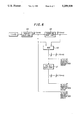
- FIGS. 3 through 7 are diagrams showing the construction of an embodiment according to the present invention, in which:
- FIG. 3 illustrates an arithmetic circuit for computing the coefficient of data Y(i);
- FIG. 4 illustrates an arithmetic circuit for computing the coefficient of data Y(i+4)
- FIG. 5 illustrates an arithmetic circuit for computing the coefficient of data Y(i-4);
- FIG. 6 illustrates an arithmetic circuit for computing the coefficient of data Y(i+8)
- FIG. 7 illustrates an adding/subtracting circuit for Y(i+1), Y(i+2), Y(i+3).
- an interpolated value f(P i ) is determined directly by the following equation based upon M items of sampling data:
- end points x i , x i+1 of an interpolating interval ⁇ i (see FIG. 1) have the greatest effect upon the interpolated value of an interpolate point P i g(x i ), g(x i+1 ) shall be referred to as main interpolated data, and data g(x i-2 ), g(x i-1 ), g(x i+2 ) . . . at the other points x i-2 , x i-1 , x i+2 . . . shall be referred to as subordinate interpolated data.
- an interpolated value is decided solely by the main interpolated data, namely the known data g(x i ) and g(x i+1 ) at the end points of the interpolating interval ⁇ i to which the point P i belongs.
- a leftward corrector D L (x i ) based upon L items of data ⁇ g(x i ),(x i-1 ), . . . g(x i-L+1 ) ⁇ to the left side of point x i but inclusive of the same is expressed by the following equation:
- a rightward corrector D R (x i+1 ) based upon R items of data ⁇ g(x i+1 ),(x i+2 ), . . . g(x i+R ) ⁇ to the right side of point x i+1 but inclusive of the same is expressed by the following equation:
- aurally natural data is obtained when an interpolated curve is determined based upon a gradient between data points at the periphery of the interpolating interval of the curve.
- the amount of correction of an interpolated point is made to the weighted sum of the first-order differences of data in the leftward and rightward directions.
- an intermediate parameter ⁇ i is calculated by floating point arithmetic based upon known data of a fixed point, and then interpolated data of the fixed point is generated. Since the amount of change in ⁇ i is very large, there are cases where a sufficient accuracy is not obtained and reproduced sounds become unnatural if all of the foregoing is processed by fixed decimal points.
- integer-type interpolated data can be generated from integer-type known data even if floating-point arithmetic is not used. As a result, reproduced sounds which are aurally natural can be obtained. Accordingly, when this method of interpolation is put into the form of hardware, it is highly advantageous for use in reproduction from a compact disk by virtue of its high speed.
- FIG. 2 is a diagram for describing the interpolating method of the invention in a case where interpolation is performed in two steps.
- items of data Y(i-4), Y(i), Y(i+4), Y(i+8) are given at points y(i-4), y(i), y(i+4), y(i+8), respectively.
- the interpolated values of intermediate points are obtained by applying the interpolating method of the present invention.
- the first step of interpolation is carried out in accordance with Eq. (8).
- the interpolated value Y(i+1) of the point y(i+1) intermediate to the points y(i) and y(i+2) can be obtained in accordance with the following equation: ##EQU3## where Y(i-2) can be obtained in accordance with the following equation using the data Y(i-8), Y(i-4), Y(i), Y(i+4) of the known data y(i-8), y(i-4), y(i), y(i+4): ##EQU4## When Eq. (8) and eq. (9) are substituted into Eq.
- the interpolated value Y(i+3) of y(i+3) which is a point intermediate to the points y(i+2) and y(i+4), can be obtained in accordance with the following equation: ##EQU7## where Y(i+6) can be obtained in accordance with the following equation using the data Y(i), Y(i+4), Y(i+8), Y(i+12) of the known data points y(i), y(i+4), y(i+8), y(i+12): ##EQU8##
- the second step of interpolation is carried out in accordance with Eqs. (9) and (10).
- These computation equations (8) through (10) include the operations of addition, subtraction and division by powers of 2.
- addition and subtraction are integer-type arithmetic operations and therefore can be performed at high speed.
- division by a power of 2 is performed by shifting bits to the right, this is achieved by the wiring in hardware. Accordingly, it is easy to realize the computation equations in the form of hardware. If the number of interpolation steps is made large, highly precise interpolated points are connected and obtained at high speed.
- FIGS. 3 through 7 are diagrams illustrating the construction of an embodiment of the invention for a case where the number of interpolation steps is two. These illustrate examples for a case where three interpolated points y(i+1), y(i+2), y(i+3) are interpolated between two intermediate points y(i), y(i+4) using the data Y(i-4), Y(i), Y(i+4), Y(i+8) of the four known data points y(i-4), y(i), y(i+4), y(i+8) shown in FIG. 2.
- FIG. 3 shows an arithmetic circuit for computing a portion relating to the data Y(i) in Eqs. (8)-(10).
- the arithmetic circuit comprises one-bit, right-shift circuits 11-13, a three bit, right-shift circuit 14, a five-bit, right-shift circuit 15, and adder circuits 16-18. This arithmetic circuit computes the following:
- FIG. 4 shows an arithmetic circuit for computing a portion relating to the data Y(i+4) in Eqs. (8)-(10).
- the arithmetic circuit comprises one-bit, right-shift circuits 21-23, a three-bit, right-shift circuit 24, a five-bit, right-shift circuit 25, and adder circuits 26 28. This arithmetic circuit computes the following:
- FIG. 5 shows an arithmetic circuit for computing a portion relating to the data Y(i-4) in Eqs. (8)-(10).
- the arithmetic circuit comprises a one-bit, right-shift circuit 31, a three-bit, right-shift circuit 32, a four-bit, right shift circuit 33, and an adder circuit 34. This arithmetic circuit computes the following:
- FIG. 6 shows an arithmetic circuit for computing a portion relating to the data Y(i+8) in Eqs. (8)-(10).
- the arithmetic circuit comprises a one-bit, right-shift circuit 41, a three-bit, right-shift circuit 42, a four-bit, right-shift circuit 43, and an adder circuit 44. This arithmetic circuit computes the following:
- numerals 51, 52, 53 respectively denote a Y(i+1) adding/subtracting circuit, a Y(i+2) adding/subtracting circuit and a Y(i+3) adding/subtracting circuit for computing interpolated data Y(i+1), Y(i+2) and Y(i+3), respectively.
- these circuits compute the interpolated values of the interpolated data Y(i+1), Y(i+2) and Y(i+3) at the three interpolated points y(i+1), y(i+2) and y(i+3) by performing the addition/subtraction operations of Eqs. (8), (9) and (10).
- a simplification may be achieved in which portions that become the same algorithm are changed over by a switch.
- interpolated values of the three points ⁇ y(i+1), y(i+2) and y(i+3) ⁇ are obtained by introducing the data of the four points ⁇ y(i-4), y(i), y(i+4), y(i+8) ⁇ , and therefore efficiency is excellent.
- interpolation steps are two in number.
- interpolation of any number of steps can be carried out by successively repeating the computations of Eqs. (8), (9) and (10) using the interpolated values obtained by the interpolation operation.
- n-step interpolation it is possible to interpolate, by computation, interpolated data at (2 n-1 )-number of interpolated points which divide, into 2 n -number of approximately equal portions, the interval between two intermediate items of data with the exception of the two items of data at the ends of four items of consecutive data.
- the purpose of the interpolating method is to obtain smooth, natural data. In order to arrange it so that visual unnaturalness will not appear in a case where a sequence of points obtained by interpolation is displayed, it is necessary to make a comparison with a smooth curve. Interpolated points are obtained using a higher order curve having continuity, and the accuracy of interpolation is evaluated by the difference between the point sequence of the interpolated points and a point sequence obtained by the interpolating method of the present invention.
- pictorial data (data specifying color) that has been stored in an image memory which corresponds to a pixel is read out sequentially and displayed.
- the content of an ordinary image memory integer-type data is of eight to 32 bits.
- a method of presenting a pictorial display in computer graphics entails deciding integer-type pictorial data corresponding to a fine grid based upon integer-type known pictorial data corresponding to a grid having a large spacing. Accordingly, if all computations are performed in the form of integers in the process for generating pictorial data, computation time can be greatly curtailed. It is better not to use floating-point arithmetic.
- this method of interpolation is such that many interpolated points are obtained by addition, subtraction and bit shifts. Accordingly, it is possible to obtain interpolated values at high speed by such operations. Further, since interpolated values are found by using local data, the method is suited to parallel processing and a further increase in speed is possible.
- the interpolating method according to the invention is suited to a graphic processor or the like which applies parallel processing to an operation while a block transfer is performed from a memory corresponding to a pixel.
- the interpolating method of the invention determines the values of interpolated points locally, there is no sudden increase in computation time even if the number of data items is large.
- spline interpolation is an indirect method. More specifically, the coefficients of a spline function are obtained based upon continuity of higher degree at a nodal point, and position information indicative of the position of a pixel is introduced to the function decided, thereby generating pictorial data of the pixel. When spline coefficients are actually obtained, pictorial data for an infinitely small pixel can be generated.
- the values of points between grid points are obtained by interpolation, with a point sequence ⁇ X n ⁇ on a one-dimensional grid calculated by a curve described by a known function being the given data, and accuracy is evaluated by making a comparison with the values decided based upon the original function values.
- interpolated values can be obtained by integer-type arithmetic consisting merely of addition, subtraction and bit shifting operations. Moreover, parallel processing is possible. As a result, interpolated values can be obtained at high speed. For example, it is possible to perform processing at a speed several hundred times higher than with interpolation using floating point arithmetic. Processing at a speed more than a thousand times higher also may be made possible by adopting a hardware arrangement as well as parallel processing.
- a new interpolating method free of the drawbacks of the conventional spline interpolating method, namely low speed and a decline in interpolating accuracy that is caused by the oscillatory phenomenon.
- the interpolating method of the invention is implemented by hardware such as integrated circuitry and an apparatus which performs playback using this hardware is constructed, video-signal sampling points and many interpolated values between these sampling points can be obtained at high speed and accuracy. As a result, high-quality sound can be reproduced in a very short period of time.
- the interpolating method of the present invention can be applied to a case where an image is processing at high speed and displayed, e.g., a case where an image is displayed upon being enlarged. More specifically, in a situation where an image is enlarged four times so that a very fine portion thereof may be observed, the interpolating method of the present invention is applied twice (two-step interpolation) to obtain intermediate points as well as points intermediate these intermediate points, thereby making it possible to display a highly accurate image at high speed.
- a real-time display of a temperature or pressure distribution, etc. is required.
- the method of the invention is applicable to such a real-time display.
- a free curved surface can be constructed by giving a plurality of points to create a wire-frame model and applying the interpolating method of the invention to this model. This makes it possible to generate machining data for injection molding.
- the interpolating method of the present invention can be applied when creating an NC tape for machining a workpiece by interpolating several interpolated points between known points and moving a tool along a curve which connects these known points and interpolated points.
- Pictorial data can be reproduced at high speed by compressing pictorial data indicative of images and the like, transmitting or storing the data, and then applying the interpolating method of the present invention.
Abstract
f(P.sub.i)=[g(x.sub.i-1)+g(x.sub.i+1)-g(x.sub.i+2)]/2.sup.N
Description
f(P.sub.i)=Ψ(P.sub.i ; φ.sub.1, φ.sub.2, . . . φ.sub.m)
f(P.sub.i)=[g(x.sub.i)-g(x.sub.i-1)+g(x.sub.i+1) -g(x.sub.i+2)]/2.sup.N +[g(x.sub.i)+g(x.sub.i+1)]/2
f(P.sub.i)=F[g(x.sub.i), . . . g(x.sub.m)] (1)
D.sub.L (x.sub.i)=Γ.sub.L {g(x.sub.i), g(x.sub.i-1), . . . g(x.sub.i-L+1)} (2)
D.sub.R (x.sub.i+1)=Γ.sub.R {g(x.sub.i+1), g(x.sub.i+2), . . . g(x.sub.i+R)} (3)
D.sub.L (x.sub.i)=λ[g(x.sub.i)-g(x.sub.i-1)] (4)
D.sub.R (x.sub.i+1)=λ[g(x.sub.i+1)-g(x.sub.i+2)] (5)
λ=1/2.sup.N =1/Λ (6)
f(P.sub.i)=[g(x.sub.i)-g(x.sub.i-1)+g(x.sub.i+1)-g(x.sub.i+2)]/2.sup.N +[g(x.sub.i)+g(x.sub.i+1)]/2 (7)
{1/2.sup.1 +1/2.sup.4 }·Y(i);
{1/2.sup.1 +1/2.sup.2 +1/2.sup.4 +1/2.sup.5 }·Y(i); and
{1/2.sup.2 +1/2.sup.7 }·Y(i).
{1/2.sup.1 +1/2.sup.4 }·Y(i+4);
{1/2.sup.2 +1/2.sup.7 }·Y(i+4); and
{1/2.sup.1 +1/2.sup.2 +1/2.sup.4 +1/2.sup.5 }·Y(i+4).
{1/2.sup.4 }·Y(i-4);
{1/2.sup.4 +1/2.sup.7 }·Y(i-4); and
{1/2.sup.5 +1/2.sup.8 }·Y(i-4).
{1/2.sup.4 }·Y(i+8);
{1/2.sup.5 +1/2.sup.8 }·Y(i+8); and
{1/2.sup.4 +1/2.sup.7 }·Y(i+8).
Claims (4)
f(P.sub.i)=(g(x.sub.i)-g(x.sub.i-1)+g(x.sub.i+1)-g(x.sub.i+2)/2.sup.N +(g(x.sub.i)+g(x.sub.i+1)/2
Applications Claiming Priority (2)
| Application Number | Priority Date | Filing Date | Title |
|---|---|---|---|
| JP2-336509 | 1990-11-30 | ||
| JP2336509A JPH04207516A (en) | 1990-11-30 | 1990-11-30 | Interpolation method |
Publications (1)
| Publication Number | Publication Date |
|---|---|
| US5258938A true US5258938A (en) | 1993-11-02 |
Family
ID=18299868
Family Applications (1)
| Application Number | Title | Priority Date | Filing Date |
|---|---|---|---|
| US07/799,098 Expired - Lifetime US5258938A (en) | 1990-11-30 | 1991-11-27 | Interpolating method using bit-shift and addition/subtraction operations |
Country Status (2)
| Country | Link |
|---|---|
| US (1) | US5258938A (en) |
| JP (1) | JPH04207516A (en) |
Cited By (14)
| Publication number | Priority date | Publication date | Assignee | Title |
|---|---|---|---|---|
| US5420887A (en) * | 1992-03-26 | 1995-05-30 | Pacific Communication Sciences | Programmable digital modulator and methods of modulating digital data |
| WO1995017728A1 (en) * | 1993-12-23 | 1995-06-29 | Genesis Microchip Inc. | Method and apparatus for quadratic interpolation |
| FR2751105A1 (en) * | 1996-07-12 | 1998-01-16 | Thomson Csf | METHOD AND DEVICE FOR CALCULATING APPROACH OF THE EXPONENTIAL MEAN OF A SUITE OF NUMBERS CODED IN THE FLOATING POINT FORMAT |
| US5740089A (en) * | 1994-02-26 | 1998-04-14 | Deutsche Itt Industries Gmbh | Iterative interpolator |
| US5792970A (en) * | 1994-06-02 | 1998-08-11 | Matsushita Electric Industrial Co., Ltd. | Data sample series access apparatus using interpolation to avoid problems due to data sample access delay |
| US5812983A (en) * | 1995-08-03 | 1998-09-22 | Kumagai; Yasuo | Computed medical file and chart system |
| US6157937A (en) * | 1997-07-17 | 2000-12-05 | Nec Corporation | High speed interpolation circuit with small circuit scale |
| US6373592B1 (en) * | 1997-07-08 | 2002-04-16 | Fuji Photo Film Co., Ltd. | Method and apparatus for generating image file |
| US6573890B1 (en) | 1998-06-08 | 2003-06-03 | Microsoft Corporation | Compression of animated geometry using geometric transform coding |
| EP1376382A2 (en) * | 2002-04-26 | 2004-01-02 | Xerox Corporation | Method and system for efficient interpolation using programmable node spacing |
| US6681165B2 (en) * | 2000-09-25 | 2004-01-20 | Nsk Ltd. | Control device for electric power steering apparatus |
| US20040230391A1 (en) * | 2003-05-15 | 2004-11-18 | Jorgensen Jerry D. | Method, apparatus and system for digital data resampling utilizing fourier series based interpolation |
| US20060279583A1 (en) * | 2005-06-13 | 2006-12-14 | Eiki Obara | Information processing apparatus and image processing method |
| USRE47238E1 (en) * | 1999-10-21 | 2019-02-12 | Lg Electronics Inc. | Filtering control method for improving image quality of bi-linear interpolated image |
Families Citing this family (1)
| Publication number | Priority date | Publication date | Assignee | Title |
|---|---|---|---|---|
| JP3090043B2 (en) * | 1996-06-03 | 2000-09-18 | 日本電気株式会社 | Digital interpolation filter circuit |
Citations (3)
| Publication number | Priority date | Publication date | Assignee | Title |
|---|---|---|---|---|
| US4313173A (en) * | 1980-06-10 | 1982-01-26 | Bell Telephone Laboratories, Incorporated | Linear interpolator |
| US4460890A (en) * | 1982-01-21 | 1984-07-17 | Sony Corporation | Direct digital to digital sampling rate conversion, method and apparatus |
| US4802109A (en) * | 1986-03-18 | 1989-01-31 | Kabushiki Kaisha Toshiba | Data-processing system for obtaining expanded and interpolated data |
Family Cites Families (2)
| Publication number | Priority date | Publication date | Assignee | Title |
|---|---|---|---|---|
| JPS6386069A (en) * | 1986-09-30 | 1988-04-16 | Toshiba Corp | Interpolation circuit |
| JPH02131009A (en) * | 1988-11-10 | 1990-05-18 | Mitsubishi Electric Corp | Data interpolation device |
-
1990
- 1990-11-30 JP JP2336509A patent/JPH04207516A/en active Pending
-
1991
- 1991-11-27 US US07/799,098 patent/US5258938A/en not_active Expired - Lifetime
Patent Citations (3)
| Publication number | Priority date | Publication date | Assignee | Title |
|---|---|---|---|---|
| US4313173A (en) * | 1980-06-10 | 1982-01-26 | Bell Telephone Laboratories, Incorporated | Linear interpolator |
| US4460890A (en) * | 1982-01-21 | 1984-07-17 | Sony Corporation | Direct digital to digital sampling rate conversion, method and apparatus |
| US4802109A (en) * | 1986-03-18 | 1989-01-31 | Kabushiki Kaisha Toshiba | Data-processing system for obtaining expanded and interpolated data |
Cited By (25)
| Publication number | Priority date | Publication date | Assignee | Title |
|---|---|---|---|---|
| US5420887A (en) * | 1992-03-26 | 1995-05-30 | Pacific Communication Sciences | Programmable digital modulator and methods of modulating digital data |
| US5600678A (en) * | 1992-03-26 | 1997-02-04 | Pacific Communication Sciences, Inc. | Programmable digital modulator and methods of modulating digital data |
| US5937010A (en) * | 1992-03-26 | 1999-08-10 | Rockwell Semiconductor Systems, Inc. | Sample interpolator and method of generating additional samples of a sampled waveform using a programmable sample divider |
| WO1995017728A1 (en) * | 1993-12-23 | 1995-06-29 | Genesis Microchip Inc. | Method and apparatus for quadratic interpolation |
| US5740089A (en) * | 1994-02-26 | 1998-04-14 | Deutsche Itt Industries Gmbh | Iterative interpolator |
| US5792970A (en) * | 1994-06-02 | 1998-08-11 | Matsushita Electric Industrial Co., Ltd. | Data sample series access apparatus using interpolation to avoid problems due to data sample access delay |
| US5812983A (en) * | 1995-08-03 | 1998-09-22 | Kumagai; Yasuo | Computed medical file and chart system |
| FR2751105A1 (en) * | 1996-07-12 | 1998-01-16 | Thomson Csf | METHOD AND DEVICE FOR CALCULATING APPROACH OF THE EXPONENTIAL MEAN OF A SUITE OF NUMBERS CODED IN THE FLOATING POINT FORMAT |
| WO1998003034A1 (en) * | 1996-07-12 | 1998-01-22 | Thomson-Csf | Method and device for the approximative computation of the exponential mean of a sequence of coded numbers in floating point format |
| US6144978A (en) * | 1996-07-12 | 2000-11-07 | Thomson-Csf | Method and device for the approximative computation of the exponential mean of a sequence of coded numbers in floating point format |
| US6373592B1 (en) * | 1997-07-08 | 2002-04-16 | Fuji Photo Film Co., Ltd. | Method and apparatus for generating image file |
| US6157937A (en) * | 1997-07-17 | 2000-12-05 | Nec Corporation | High speed interpolation circuit with small circuit scale |
| US6573890B1 (en) | 1998-06-08 | 2003-06-03 | Microsoft Corporation | Compression of animated geometry using geometric transform coding |
| US6614428B1 (en) * | 1998-06-08 | 2003-09-02 | Microsoft Corporation | Compression of animated geometry using a hierarchical level of detail coder |
| USRE47238E1 (en) * | 1999-10-21 | 2019-02-12 | Lg Electronics Inc. | Filtering control method for improving image quality of bi-linear interpolated image |
| USRE47274E1 (en) * | 1999-10-21 | 2019-03-05 | Lg Electronics Inc. | Filtering control method for improving image quality of bi-linear interpolated image |
| USRE47291E1 (en) * | 1999-10-21 | 2019-03-12 | Lg Electronics Inc. | Filtering control method for improving image quality of bi-linear interpolated image |
| USRE47310E1 (en) | 1999-10-21 | 2019-03-19 | Lg Electronics Inc. | Filtering control method for improving image quality of bi-linear interpolated image |
| USRE47337E1 (en) | 1999-10-21 | 2019-04-02 | Lg Electronics Inc. | Filtering control method for improving image quality of bi-linear interpolated image |
| USRE47341E1 (en) * | 1999-10-21 | 2019-04-09 | Lg Electronics Inc. | Filtering control method for improving image quality of bi-linear interpolated image |
| US6681165B2 (en) * | 2000-09-25 | 2004-01-20 | Nsk Ltd. | Control device for electric power steering apparatus |
| EP1376382A2 (en) * | 2002-04-26 | 2004-01-02 | Xerox Corporation | Method and system for efficient interpolation using programmable node spacing |
| US20040230391A1 (en) * | 2003-05-15 | 2004-11-18 | Jorgensen Jerry D. | Method, apparatus and system for digital data resampling utilizing fourier series based interpolation |
| US6915225B2 (en) * | 2003-05-15 | 2005-07-05 | Northrop Grumman Corporation | Method, apparatus and system for digital data resampling utilizing fourier series based interpolation |
| US20060279583A1 (en) * | 2005-06-13 | 2006-12-14 | Eiki Obara | Information processing apparatus and image processing method |
Also Published As
| Publication number | Publication date |
|---|---|
| JPH04207516A (en) | 1992-07-29 |
Similar Documents
| Publication | Publication Date | Title |
|---|---|---|
| US5258938A (en) | Interpolating method using bit-shift and addition/subtraction operations | |
| US5278948A (en) | Parametric surface evaluation method and apparatus for a computer graphics display system | |
| US7034823B2 (en) | 3D computer graphics processing apparatus and method | |
| US5317682A (en) | Parametric curve evaluation method and apparatus for a computer graphics display system | |
| JP3318914B2 (en) | System and method for rendering Bezier splines | |
| US5257355A (en) | Method and apparatus for generating non-linearly interpolated data in a data stream | |
| US5608856A (en) | Computer graphics apparatus and method for interpolating control values to generate image data | |
| US6014143A (en) | Ray transform method for a fast perspective view volume rendering | |
| GB2415118A (en) | Calculating a surface normal in a 3D graphics system | |
| US4571697A (en) | Apparatus for calculating pattern dissimilarity between patterns | |
| JPH10215147A (en) | Interpolation unit using plural polynomials and related method | |
| Pulleyblank et al. | The Feasibility of a VLSI Chip for Ray Tracing Bicublic Patches | |
| US4736248A (en) | Method and device for generating intermediate picture signals from reference picture signals having a reduced picture frequency | |
| EP0412826A1 (en) | Digital signal processing | |
| US6094503A (en) | Image transforming method and apparatus | |
| US7151862B2 (en) | Image processing apparatus and method, storage medium, and program | |
| US6195461B1 (en) | Dynamic image processing apparatus and method | |
| JPH0664089B2 (en) | Sampling signal processor | |
| GB2278469A (en) | Methods and apparatus for interpolating received values, image synthesis and picture recordings | |
| EP0425174A2 (en) | Parametric curve evaluation for a computer graphics display system | |
| JPH05282354A (en) | Interpolating method and waveform display device using interpolating method concerned | |
| US6256654B1 (en) | Signal interpolation and decimation exploiting filter symmetry | |
| JP2867411B2 (en) | Contour data generation device | |
| JPH06274524A (en) | Orthogonal transformation circuit and inverse transformation circuit | |
| Roche et al. | A Note on Real Time Parametric Cubic Segment Curve Generation |
Legal Events
| Date | Code | Title | Description |
|---|---|---|---|
| AS | Assignment |
Owner name: AKAMATSU, NORIO Free format text: ASSIGNMENT OF ASSIGNORS INTEREST.;ASSIGNOR:AKAMATSU, NORIO;REEL/FRAME:005977/0240 Effective date: 19911111 Owner name: ALPINE ELECTRONICS INC. Free format text: ASSIGNMENT OF ASSIGNORS INTEREST.;ASSIGNOR:AKAMATSU, NORIO;REEL/FRAME:005977/0240 Effective date: 19911111 Owner name: AKAMATSU, NORIO, JAPAN Free format text: ASSIGNMENT OF ASSIGNORS INTEREST;ASSIGNOR:AKAMATSU, NORIO;REEL/FRAME:005977/0240 Effective date: 19911111 Owner name: ALPINE ELECTRONICS INC., JAPAN Free format text: ASSIGNMENT OF ASSIGNORS INTEREST;ASSIGNOR:AKAMATSU, NORIO;REEL/FRAME:005977/0240 Effective date: 19911111 |
|
| STCF | Information on status: patent grant |
Free format text: PATENTED CASE |
|
| FPAY | Fee payment |
Year of fee payment: 4 |
|
| FPAY | Fee payment |
Year of fee payment: 8 |
|
| FEPP | Fee payment procedure |
Free format text: PAYOR NUMBER ASSIGNED (ORIGINAL EVENT CODE: ASPN); ENTITY STATUS OF PATENT OWNER: LARGE ENTITY |
|
| FPAY | Fee payment |
Year of fee payment: 12 |