US5301313A - Manipulating data in a relational data base having operational manipulations defined in an input table and displayed results in an output table with a line displayed designating direction of data flow - Google Patents
Manipulating data in a relational data base having operational manipulations defined in an input table and displayed results in an output table with a line displayed designating direction of data flow Download PDFInfo
- Publication number
- US5301313A US5301313A US07/730,173 US73017391A US5301313A US 5301313 A US5301313 A US 5301313A US 73017391 A US73017391 A US 73017391A US 5301313 A US5301313 A US 5301313A
- Authority
- US
- United States
- Prior art keywords
- data
- manipulation
- input
- operational
- defining
- Prior art date
- Legal status (The legal status is an assumption and is not a legal conclusion. Google has not performed a legal analysis and makes no representation as to the accuracy of the status listed.)
- Expired - Lifetime
Links
Images


Classifications
-
- G—PHYSICS
- G06—COMPUTING; CALCULATING OR COUNTING
- G06F—ELECTRIC DIGITAL DATA PROCESSING
- G06F3/00—Input arrangements for transferring data to be processed into a form capable of being handled by the computer; Output arrangements for transferring data from processing unit to output unit, e.g. interface arrangements
- G06F3/01—Input arrangements or combined input and output arrangements for interaction between user and computer
- G06F3/02—Input arrangements using manually operated switches, e.g. using keyboards or dials
- G06F3/023—Arrangements for converting discrete items of information into a coded form, e.g. arrangements for interpreting keyboard generated codes as alphanumeric codes, operand codes or instruction codes
-
- G—PHYSICS
- G06—COMPUTING; CALCULATING OR COUNTING
- G06F—ELECTRIC DIGITAL DATA PROCESSING
- G06F16/00—Information retrieval; Database structures therefor; File system structures therefor
- G06F16/20—Information retrieval; Database structures therefor; File system structures therefor of structured data, e.g. relational data
- G06F16/24—Querying
- G06F16/242—Query formulation
- G06F16/2428—Query predicate definition using graphical user interfaces, including menus and forms
-
- Y—GENERAL TAGGING OF NEW TECHNOLOGICAL DEVELOPMENTS; GENERAL TAGGING OF CROSS-SECTIONAL TECHNOLOGIES SPANNING OVER SEVERAL SECTIONS OF THE IPC; TECHNICAL SUBJECTS COVERED BY FORMER USPC CROSS-REFERENCE ART COLLECTIONS [XRACs] AND DIGESTS
- Y10—TECHNICAL SUBJECTS COVERED BY FORMER USPC
- Y10S—TECHNICAL SUBJECTS COVERED BY FORMER USPC CROSS-REFERENCE ART COLLECTIONS [XRACs] AND DIGESTS
- Y10S707/00—Data processing: database and file management or data structures
- Y10S707/99931—Database or file accessing
- Y10S707/99933—Query processing, i.e. searching
- Y10S707/99934—Query formulation, input preparation, or translation
Definitions
- the present invention relates generally to a system and a method of manipulating a data base, and more particularly, to a system of manipulating a relational data base.
- One data base systems directed to making information resources available to users by means of an abbreviated language is a relational data base system.
- Data is stored in the form of table in the relational data base system.
- a table is constituted as shown in FIG. 1, for example, including a table name 100 indicative of the entire contents of the table and item names 101a and 101b for identifying the contents of the respective columns.
- Data 102a and 102b are placed under the item names 101a and 101b, respectively.
- the relational data base stores a plurality of tables.
- a table name 100 varies from table to table in order to identify each table.
- an item name also varies from column to such column that each column is distinguishable from other columns.
- a table of a relational data bases comprises a row 103 and columns 104a and 104b.
- the row 103 is a group of data elements (102a, 102b) related to a particular event.
- the relational data base system bases on a relational model.
- the relational model meets the following three requirements.
- an internal data construction takes a form of table as shown in FIG. 1, the order of rows and columns thereof is not defined.
- the table is referred to as a relation table and corresponds to a file.
- a row corresponds to a record.
- a column is referred to as attribute or an item and corresponds to a field.
- a data manipulation language is prepared which is used for manipulation based on relational algebra.
- SQL structured query language
- QBE query by example
- SQL is a command type language having such a function as data definition (definition of a table and of data manipulation).
- the command type denotes a format which allows a user to give an instruction through a terminal equipment under TSS (time sharing system) without using a program.
- the SQL is an non-procedure language which gives only an instruction on "what we want”.
- the QBE is a display based (example type) language which allows a user to give an instruction by setting conditions at an appropriate column while looking at a frame of the table displayed on a terminal equipment.
- a SQL type language is structured to implement instructions from definition of a table for manipulation and deletion within one language system
- a QBE type language is structured to implement only manipulation of a table.
- the relational data base system provides also an instruction type referred to as a storage type in which previously stored instruction on manipulation of a relational data base is called for execution whenever necessary.
- Manipulation of a relational data base such as modification, deletion and search of a table requires definition of an operation procedure in a text format by utilizing such commands as "SELECT", “FROM” and “WHERE", for example, in a SQL type language.
- Almost all the data as objectives of manipulation of a relational data base are data of table format based on the above-described relation table. It is not necessarily easy for a user to define an operation procedure while regrasping in a text format the data construction from such table format.
- the software provides independent graphical editing means for designing of data structure, layout of display data and such. Complicated manipulation procedures should be described using a flow chart even with this software.
- An object of the present invention is to provide a data base manipulation environment with high operability and understandability for a data base.
- the data base manipulation system includes first means for describing input data including an input table as an object for manipulation and an output table in which manipulation results are displayed when output data is represented in the table format, second means for describing, in a non-text format, all the operation at manipulations to be performed on the above-described input data described in the table format, and means for accessing a relational data base in response to the data from the above-described first and second means.
- the above-described input table in which input data which are objects for manipulation and represented in a table format has a region wherein operational manipulations are described, and the output table indicative of manipulation results has a region wherein map relations between the input table data and the output table data are described.
- Manipulation flow is represented by a connection line with directionality to allow a description of an operational manipulation on the input data represented in a table format without using a text format.
- the first means describes the input table as an object of manipulation and the output table indicative of a manipulation result in a table format.
- the second means describes an operational manipulation at a predetermined region of the input data represented by the first means, thereby defining the contents of the manipulation.
- FIG. 1 is a diagram showing an example of an construction of a table of a relational data base.
- FIG. 2 is a diagram showing an construction of a basic representation on a data base manipulation system according to the present invention.
- FIGS. 3, 4, 5, 6, 7, 8, and 9 are diagrams specifically showing description manners of a basic manipulation for use in the data base manipulation system according to the present invention.
- FIG. 10 is a diagram showing an example of a manner of describing a complicated manipulation procedure by combining basic manipulations in the data base operation system according to the present invention.
- FIG. 11 is a diagram showing an example of a description manner of describing a larger-scaled operation procedure by combining a plurality of manipulation procedures.
- FIGS. 12(a) and 12(b) are diagrams which show an example of an operation of defining a data construction for forming a basic relation table.
- FIG. 13 is a diagram showing an example of operation manner in changing a data construction of a relation table.
- FIG. 14 is a diagram showing an example of a manner in describing data in a relation table.
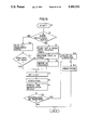
- FIG. 15 is a flow chart showing operation in the data base manipulation system according to the present invention.
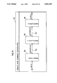
- FIG. 16 is a schematic diagram showing an entire construction of a data base manipulation system according to one embodiment of the present invention.
- FIG. 2 shows a basic construction of a data base manipulation system according to the present invention.
- a table 1a (relation table: referred to as an input table hereinafter) representing data as objects of manipulation
- a table 1b (hereinafter referred to as an output table) representing data obtained as a result of manipulation.
- the input table 1a and the output table 1b represent input data.
- the input table 1a includes an operational manipulation description region 2 defining an operation with respect to the input table 1a under each item (product name code, product name or the like) of item name description region 3b and a table name description region 3a wherein a table name is described.
- the output table 1b includes, in addition to the item name description region 3b and the table name description region 3a, a mapping relation description region 4 for describing a map relation between each item in the table 1a and each item in the table 1b, under the item name description region 3b.
- the operational manipulation description region 2 in the table 1a is connected to an input line 5 indicative of an input of key data (primary key) to be applied to an operational manipulation described in an associated description region 2.
- connection line 6 indicative of a manipulation flow for showing which is an object for manipulation and which is a result of the manipulation.
- the connection line 6 is shown by an arrow, a direction of which arrow identifies an input table as an object for manipulation and an output table indicative of a manipulation result.
- the connection line 6 is illustrated facing right to indicate that the data in the table 1b is generated from the data in the table 1a.
- the display screen 150 further includes an operation name description region 7 wherein a name defined by the diagrams of the manipulation table is described. A method of describing the basic manipulations will be specifically described in the following.
- FIG. 3 shows one example of a manner of describing a projection manipulation.
- "Projection” is a manipulation of extracting a particular column (item) from a table. The conditions of projection are written as table names and item names in the mapping relation description region 4 in the output table 1b.
- FIG. 3 shows a manipulation of extracting a product name, the quantity of the product and a container number in a product list described in the input table 1a and describing the same in an inventory written in the output table 1b.
- FIG. 4 shows one example of a manner of describing restriction condition.
- "Restriction” is a manipulation of extracting a row meeting a particular condition from a table.
- "restriction” condition 12 is described under the item name to be restricted in the operational manipulation description region 2 in the input table 1a.
- key data for the "restriction” condition 12 is separately supplied.
- FIG. 4 shows an example of a manipulation of making a new inventory by extracting a product code and a container number of a product equivalent to "brand” supplied through the input line 5 from the product list described in the input table 1a.
- FIG. 5 is a diagram showing a manner of describing a union manipulation.
- "Union” is a manipulation of linking a reference result of a table together with a reference result of another table.
- the "union” manipulation is denoted by connection lines 6, 6'.
- connection lines 6, 6' Through the connection lines 6, 6', an input initial value a is mapped into the output table 1b to constitute the data of the output table 1b and a second input initial value b is subjected to a projection manipulation, thereby forming the output table 1b with each item linked together with the corresponding item of the input table 1a.
- FIG. 6 is a diagram showing an example of a manner of describing a join manipulation.
- "Join” is a manipulation of creating a table based on two or more tables. Conditions of this "join” are described in a condition description region 20 provided between the input tables 1a and 1c, and the output table lb.
- FIG. 6 shows, as an example, a case where another inventory is created as an output table 1b by extracting the product with the same product code name and the quantity from the respective input tables 1a and 1b.
- FIG. 7 shows one example of a manner of describing a direct product manipulation.
- "Direct product” is a manipulation of creating a table based on the combination of various data in a plurality of tables.
- an asterisk mark 23 indicative of "direct product” is described in the condition description region 20.
- FIG. 7 shows creation of a new inventory based on the respective data (items) in the input tables 1a and 1c.
- FIG. 8 shows an example of a manner of describing a sorting manipulation.
- "Sorting” is a manipulation of rearranging data in a certain table under particular conditions imposed to a certain item.
- a "sorting" manipulation includes a manipulation AO for sorting data in an ascending order and a manipulation DO for sorting data in a descending order. Sorting conditions are described in the operational manipulation description region 2 under an item to be sorted in the input table 1a.
- FIG. 8 shows, as an example, a manipulation of sorting the data in the input table 1a in the alphabetical order of product names or in the ascending order of the Japanese syllabary.
- FIG. 9 is a diagram showing one example of a manner of defining a calculation manipulation.
- An operator 26 for prescribing a calculation manipulation is described in the operational manipulation description region 2 under an item to be calculated in the input table 1a.
- the example shown in FIG. 9 represents a manipulation for obtaining a maximum quantity among the quantities of the products described in the inventory 1a.
- Operators for describing a calculation manipulation include "SUM” for obtaining a total value, "AVG” for obtaining a mean value, "MIN” for obtaining a minimum value, "CNT” for obtaining the number of rows.
- a data output obtained as a result of calculation is described by means of an output line 28. In the example shown in the drawing, a value indicative of a maximum of the numbers of the products described in the inventory is extracted through the output line 28.
- FIG. 10 shows one example of data base manipulations which are a combination of basic manipulations.
- a data base manipulation is shown as an example which combines a restriction manipulation, a union manipulation, a projection manipulation and a calculation operation. More specifically, the restriction "select data with the container number coincident with the container number supplied through the input line 5 " is described in the operational manipulation description region 2a in the input table 1c. The input table 1c after the restriction is united with the input table 1a, thereby creating the output table 1b. The union of the input tables 1a and 1c is described by means of the connection lines 6, 6'. The conditions of projection of the input table 1c onto the output table 1b is described in a mapping condition description region 4 in the output table 1b.
- the operator "SUM" is described in an operational manipulation description region 2b in the input table 1c.
- the result of the calculation manipulation is extracted as output data by the output line 28.
- a sum of the total quantities of the products described in the product list 1c is output as output data.
- More complicated and larger-scaled data base manipulation can be defined by linking together each representation (identified by a manipulation name described in the manipulation name description region 7) wherein a procedure of this data base manipulation is described.
- FIG. 11 is a diagram showing one example of a description manner defining a larger-scaled manipulation by linking a plurality of data base manipulations together.
- FIG. 11 shows, as an example, a description manner in sequentially executing a first manipulation 29a, a second manipulation 29b and a third manipulation 29c.
- a data flow in the procedure of the manipulations 29a-29c is described by means of the connection lines 30a and 30b.
- the above-described data base manipulation system allows graphic description of all the manipulations in an interactive manner to make the data base manipulation system more convenient and understandable for a user.
- An construction for materializing the above-described data base manipulation system will be described. Creation of a relation table will be first described.
- an appropriate relation table is selected among previously prepared basic input relation tables.
- a name of the table as an object for manipulation is described in the table name description region 3a in this selected relation table. This name description may be done through movement of a cursor to an appropriate position or by using a keyboard and a cursor or by using a mouse. This table name is coded without modification.
- the item names (A, B) together with the format of the data are described in the item name description regions 3b1 and 3b2. For example, an integer (int) or a string (string) is defined for the item name A.
- the input data is produced as shown in FIG. 12A.
- a record region for an construction (int, string) of the data to be filed is ensurely acquired under a heading at the relation table name description region 3a' (table name D1) within a processor (will be described later), as shown in FIG. 12B.
- a relation table to be modified is read out and instruction of a change of a data construction is provided.
- a new item C is added and data construction thereof is described (string in FIG. 13).
- the data construction (int, string, string) of the relation table is changed.
- a created relation table is read out and data to be input under each item of the read out table is written as shown in FIG. 14.
- the processor creates a record under the table name "D1" according to the defined data construction, thereby creating a data base.
- an operator or an user enable the system to activate a data base manipulation routine or an unit (step S0).
- step S1 an inquiry is made about registration of a desired relation table or a desired manipulation procedure in the system.
- Relation tables and manipulation procedures stored in the system are referred to as "parts”.
- a desired manipulation procedure or relation table is not registered, a basic input relation table previously prepared in the system is read out (step S2).
- Data is written in the read out basic input relation table to define a data construction of the table.
- a data construction related to each item in the table is registered as an identifier, the data is written in a desired region of the table by using the identifier.
- a new identifier is allotted to an item or table with no identifier allotted thereof (step S33).
- the identifier applied to a table name, the item name or a manipulation procedure name (the manipulation procedure name will be described later) is registered in the system and used as a key for a future reference of the parts (step S34).
- step S11 When it is found at step S1 that the desired relation table or the desired operation procedure has already registered, a code indicative of the registered part is supplied to the system reading out the corresponding registered part (step S11).
- the registered part can be read out at a desired level of the relation table, the entire operation procedure and the partial operation procedure and it is also registrable as "part" at each respective level.
- the user makes a determination as to whether the operation procedure of the read out registered part or data item of the relation table is completely coincident with the desired operation or not (display of the respective tables on a visible display unit in the relation table allows the user to make a determination by checking the respective tables on the screen or the mutual relation therebetween).
- step S4 or S3
- Definition of a desired necessary operation is carried out on the defined relation table (input data) at step S4.
- the definition of operation is described in such a manner as shown in FIG. 2 or FIG. 10.
- setting of a necessary key is made (step S5).
- the key setting can be carried out by giving the execution instruction for the step S6 and then setting a desired key to fill the table (or item) displayed on the screen in the form of a multiwindow, for example.
- execution instruction is issued after the key setting (step S6).
- the execution result is displayed in the form of a table defined by the output table or of the calculation result value (step S7).
- Registration is designated of the relation table or the operation procedure which is determined to be registered, and the system allots a desired identifier to a part designated to be registered and stores the part (S34).
- the registered part is registered in such a graphical manner as representing the form and construction of the expressed relation tables. Therefore, a read out registered part will be displayed in the representation form as graphically describing the operation procedure in a relation table form on the screen. This enhances operability and understandability for a user, thereby improving the re-usability of a registered part.
- This data base manipulation system can be implemented on a software or hardware basis.
- FIG. 16 shows one example of an apparatus construction in a case where the data base manipulation system is implemented by using hardware.
- a data base manipulation apparatus 100 comprises an input data defining unit 112 for defining input data supplied by a user through a user IO (input/output interface) 110, operational manipulation defining unit 114 for defining an operational manipulation received from the user IO 110, a control unit 116 responsive to data from the input data defining unit 112 and the operation of calculation defining unit 114 for performing a data base operation, and an input/output data display unit 120 for displaying the input data and the output data under the control of a control unit 116.
- an input data defining unit 112 for defining input data supplied by a user through a user IO (input/output interface) 110
- operational manipulation defining unit 114 for defining an operational manipulation received from the user IO 110
- control unit 116 responsive to data from the input data defining unit 112 and the operation of calculation defining unit 114 for performing a data base operation
- an input/output data display unit 120 for displaying the input data and the output data under the control of a control unit 116.
- the control unit 116 is provided with a memory 118 for registering parts and serving as a work region for temporarily storing data.
- the memory 118 includes a temporary file TF and a permanent file PF, for example.
- the permanent file stores information on registration of parts and the temporary file TF stores data necessary for manipulation being executed. After completion of a certain program or a data base manipulation, the contents of the temporary file TF are erased. The contents of the permanent file PF are continuously maintained.
- the data base manipulation apparatus 100 writes and reads data to and from a data base file 130.
- the data base file 130 stores data of a desired relation table. Operation of the respective unit will be described in the following.
- the user IO 110 includes a graphic input device such as mouse.
- a user inputs desired data in an interactive manner while checking graphical appearing information on the input/output data display unit 120.
- the input data defining unit 112 is activated in response to an instruction for creating input data supplied from the user IO 110.
- the input data defining unit 112 refers through the control unit 116 to the part registration section (permanent file PF) of the memory 118. If the corresponding part exists, the defining unit 112 supplies the corresponding part to the input/output data display unit 120 under the control of the control unit 116.
- the user defines various necessary data with respect to the relation tables displayed on the input/output data display unit 120.
- the input data defining unit 112 correlates the definitions with each of desired data constructions, to create a relation table which is supplied to the control unit 116.
- the operation of operational manipulation defining unit 114 is activated in response to the instruction for defining operational manipulation from the user.
- the defining unit 114 receives through the user IO 110, information on operational manipulation which the user defines using a relation table or the connection line with respect to the graphics displayed on the input/output data display device 120 and makes a definition on the operational manipulation following a predetermined rule for each of received input operational manipulation information.
- the control unit 116 stores away the input data construction supplied from the input data defining unit 112 and the operational manipulation supplied from the operational manipulation defining unit 114 both in the memory 118.
- the information on definition of manipulation supplied from the operational manipulation defining unit 114 is stored in the memory 118 (temporary file TF) so as to correspond with each item or table of the input data defined by the input data defining unit 112.
- the correspondence of each manipulation with a table or item name is made by identifying a data input position on input/output display unit 120. As a result, the manipulation procedure is stored in the memory 118.
- the execution instruction given by the user through the user IO 110 activates the execution circuitry of the control unit 116, whereby the manipulation procedure supplied by the user is sequentially read out from the memory 118 for access to the data base file 130.
- the data is displayed on the input/output data display unit 120.
- the data is displayed on the input/output data display unit 120 in the form of a relation table, or of a simple numerical value when the data is a calculation result.
- control unit 116 applies identifiers to the input data information received from the input data defining unit 112 and stores the same in the memory 118.
- the unit 116 adds to the operational manipulation supplied from the operational manipulation defining unit 114, an identifier for making an operation identified with input data and stores the result in the memory 118. As a result, the order of operational manipulation is maintained.
- the control unit 116 stores the same in the permanent file (PF) of the memory 118.
- PF permanent file
- the input data defining device 112 and the operational manipulation defining unit 114 have functions of interpreting given graphical information or definition information based on a conversion table contained therein to generate the corresponding data. That is, the function of this input data defining unit 112 and the operational manipulation defining unit 114 is considered to be similar to that of an editor with drawing and editing functions.
- the present invention enables definition and execution of such operational manipulation as search, addition and modification of a data base in an interactive manner by using graphical representation in a table format, leading to defining of an operational manipulation by using language of non-text format. Therefore, a user is allowed to define manipulation procedures by using the same representation format, that is a table format, as that of original data of a relational data base, resulting in facilitating of a data base manipulation which has been conventionally complicated, and resulting in a data base manipulation system implementing an environment for description manipulation with high understandability.
Abstract
Description
Claims (12)
Applications Claiming Priority (2)
| Application Number | Priority Date | Filing Date | Title |
|---|---|---|---|
| JP2191823A JP2525275B2 (en) | 1990-07-17 | 1990-07-17 | Database operation method |
| JP2-191823 | 1990-07-17 |
Publications (1)
| Publication Number | Publication Date |
|---|---|
| US5301313A true US5301313A (en) | 1994-04-05 |
Family
ID=16281118
Family Applications (1)
| Application Number | Title | Priority Date | Filing Date |
|---|---|---|---|
| US07/730,173 Expired - Lifetime US5301313A (en) | 1990-07-17 | 1991-07-15 | Manipulating data in a relational data base having operational manipulations defined in an input table and displayed results in an output table with a line displayed designating direction of data flow |
Country Status (2)
| Country | Link |
|---|---|
| US (1) | US5301313A (en) |
| JP (1) | JP2525275B2 (en) |
Cited By (48)
| Publication number | Priority date | Publication date | Assignee | Title |
|---|---|---|---|---|
| WO1995006292A1 (en) * | 1993-08-25 | 1995-03-02 | Asymetrix Corporation | Method and apparatus for the modeling and query of database structures using natural language-like constructs |
| EP0697667A1 (en) * | 1994-06-30 | 1996-02-21 | AT&T Corp. | Method and apparatus for displaying structures and relationships of a relational database |
| US5553278A (en) * | 1992-09-21 | 1996-09-03 | Hitachi, Ltd. | Method and system for manipulation of database and issuing report thereof |
| US5611076A (en) * | 1994-09-21 | 1997-03-11 | Micro Data Base Systems, Inc. | Multi-model database management system engine for databases having complex data models |
| US5615367A (en) * | 1993-05-25 | 1997-03-25 | Borland International, Inc. | System and methods including automatic linking of tables for improved relational database modeling with interface |
| US5623658A (en) * | 1993-04-20 | 1997-04-22 | Casio Computer Co., Ltd. | Data totalizing method in data processing apparatus |
| US5630122A (en) * | 1992-04-30 | 1997-05-13 | International Business Machines Corporation | Computerized report-based interactive database query interface |
| US5642521A (en) * | 1993-06-22 | 1997-06-24 | Casio Computer Co., Ltd. | Data processing apparatus for extracting and processing arbitrary records from a file |
| US5666553A (en) * | 1992-04-10 | 1997-09-09 | Puma Technology, Inc. | Method for mapping, translating, and dynamically reconciling data between disparate computer platforms |
| US5684990A (en) * | 1995-01-11 | 1997-11-04 | Puma Technology, Inc. | Synchronization of disparate databases |
| US5787411A (en) * | 1996-03-20 | 1998-07-28 | Microsoft Corporation | Method and apparatus for database filter generation by display selection |
| US5802514A (en) * | 1996-04-09 | 1998-09-01 | Vision Software Tools, Inc. | Automated client/server development tool using drag-and-drop metaphor |
| US5805881A (en) * | 1992-11-04 | 1998-09-08 | Casio Computer Co., Ltd. | Method and apparatus for generating arbitrary output records in response to output designation of records |
| US5832489A (en) * | 1995-10-18 | 1998-11-03 | 3 Com Corporation | Method and apparatus for synchronizing information on two different computer systems |
| US5884323A (en) * | 1995-10-13 | 1999-03-16 | 3Com Corporation | Extendible method and apparatus for synchronizing files on two different computer systems |
| US5943676A (en) * | 1996-11-13 | 1999-08-24 | Puma Technology, Inc. | Synchronization of recurring records in incompatible databases |
| US5953715A (en) * | 1994-08-12 | 1999-09-14 | International Business Machines Corporation | Utilizing pseudotables as a method and mechanism providing database monitor information |
| US6006274A (en) * | 1997-01-30 | 1999-12-21 | 3Com Corporation | Method and apparatus using a pass through personal computer connected to both a local communication link and a computer network for indentifying and synchronizing a preferred computer with a portable computer |
| US6034686A (en) * | 1998-03-09 | 2000-03-07 | 3Com Corporation | Collapsing event display for small screen computer |
| US6044381A (en) * | 1997-09-11 | 2000-03-28 | Puma Technology, Inc. | Using distributed history files in synchronizing databases |
| US6108677A (en) * | 1994-11-08 | 2000-08-22 | Casio Computer Co., Ltd. | Data processing apparatus |
| US6141664A (en) * | 1996-11-13 | 2000-10-31 | Puma Technology, Inc. | Synchronization of databases with date range |
| US6205448B1 (en) | 1998-01-30 | 2001-03-20 | 3Com Corporation | Method and apparatus of synchronizing two computer systems supporting multiple synchronization techniques |
| US6212529B1 (en) | 1996-11-13 | 2001-04-03 | Puma Technology, Inc. | Synchronization of databases using filters |
| US6253326B1 (en) | 1998-05-29 | 2001-06-26 | Palm, Inc. | Method and system for secure communications |
| US6330568B1 (en) | 1996-11-13 | 2001-12-11 | Pumatech, Inc. | Synchronization of databases |
| US6360272B1 (en) | 1999-05-28 | 2002-03-19 | Palm, Inc. | Method and apparatus for maintaining a unified view of multiple mailboxes |
| US6389572B1 (en) | 1999-05-28 | 2002-05-14 | Palm, Inc. | Method of extracting bits from modulated waveforms |
| US6397259B1 (en) | 1998-05-29 | 2002-05-28 | Palm, Inc. | Method, system and apparatus for packet minimized communications |
| US6401112B1 (en) | 1997-01-29 | 2002-06-04 | Palm, Inc. | Method and apparatus for synchronizing an Email client on a portable computer system with an Email client on a desktop computer |
| US6405218B1 (en) | 1996-11-13 | 2002-06-11 | Pumatech, Inc. | Synchronizing databases |
| US6405205B1 (en) * | 1999-03-03 | 2002-06-11 | Nec Corporation | Message display method and system for reproduction of DML objects in relational databases |
| US20030195889A1 (en) * | 2002-04-04 | 2003-10-16 | International Business Machines Corporation | Unified relational database model for data mining |
| US20030217069A1 (en) * | 2002-05-10 | 2003-11-20 | International Business Machines Corporation | Method for schema mapping and data transformation |
| US6925477B1 (en) | 1998-03-31 | 2005-08-02 | Intellisync Corporation | Transferring records between two databases |
| US7007003B1 (en) | 1998-12-04 | 2006-02-28 | Intellisync Corporation | Notification protocol for establishing synchronization mode for use in synchronizing databases |
| US7013315B1 (en) | 1996-11-13 | 2006-03-14 | Intellisync Corporation | Synchronization of databases with record sanitizing and intelligent comparison |
| US7025209B2 (en) | 1998-05-29 | 2006-04-11 | Palmsource, Inc. | Method and apparatus for wireless internet access |
| US7206815B1 (en) | 1997-01-29 | 2007-04-17 | Palmsource Inc. | Method and apparatus for synchronizing an email client on a portable computer system with an email client on a desktop computer |
| US7299240B1 (en) * | 1992-04-10 | 2007-11-20 | Intellisync Corporation | Method for translating computer data from one record structure to another |
| US7302446B1 (en) | 1996-11-13 | 2007-11-27 | Intellisync Corporation | Synchronizing databases |
| US7359920B1 (en) | 2001-04-18 | 2008-04-15 | Intellisync Corporation | Communication protocol for synchronization of personal information management databases |
| US20080126376A1 (en) * | 2006-09-22 | 2008-05-29 | Avraham Leff | Enabling multi-view applications based on a relational state machine paradigm |
| US20110126120A1 (en) * | 2001-02-28 | 2011-05-26 | Brittingham Brian S | Computerized Interface For Monitoring Financial Information And Executing Financial Transactions |
| US20110196799A1 (en) * | 1995-02-13 | 2011-08-11 | Fino Timothy A | System and method for synchronizing objects between data collections |
| US8805957B2 (en) | 1998-05-29 | 2014-08-12 | Access Co., Ltd. | Method and apparatus for communications over low bandwidth communications networks |
| US10176607B2 (en) | 2017-01-25 | 2019-01-08 | International Business Machines Corporation | Interactive pattern detection in data sets |
| USD845978S1 (en) * | 2013-01-23 | 2019-04-16 | Yandex Europe Ag | Display screen with graphical user interface |
Families Citing this family (5)
| Publication number | Priority date | Publication date | Assignee | Title |
|---|---|---|---|---|
| US5421008A (en) * | 1991-11-08 | 1995-05-30 | International Business Machines Corporation | System for interactive graphical construction of a data base query and storing of the query object links as an object |
| JPH087675B2 (en) * | 1991-11-12 | 1996-01-29 | インターナショナル・ビジネス・マシーンズ・コーポレイション | Graphical inquiry system |
| JPH06337900A (en) * | 1993-05-27 | 1994-12-06 | Sony Corp | Information retrieving device |
| JP4736089B2 (en) * | 2005-01-12 | 2011-07-27 | 野田 正嗣 | Information processing apparatus, file data merging method, and file name assigning method |
| US8065267B2 (en) * | 2005-01-12 | 2011-11-22 | Masatsugu Noda | Information processing device, file data merging method, file naming method, and file data output method |
Citations (5)
| Publication number | Priority date | Publication date | Assignee | Title |
|---|---|---|---|---|
| US4506326A (en) * | 1983-02-28 | 1985-03-19 | International Business Machines Corporation | Apparatus and method for synthesizing a query for accessing a relational data base |
| US4688195A (en) * | 1983-01-28 | 1987-08-18 | Texas Instruments Incorporated | Natural-language interface generating system |
| US4791561A (en) * | 1987-04-17 | 1988-12-13 | Wang Laboratories, Inc. | Interactive construction of means for database maintenance |
| US4914568A (en) * | 1986-10-24 | 1990-04-03 | National Instruments, Inc. | Graphical system for modelling a process and associated method |
| US5091852A (en) * | 1988-01-29 | 1992-02-25 | Hitachi, Ltd. | System for optimizing query processing in a relational database |
-
1990
- 1990-07-17 JP JP2191823A patent/JP2525275B2/en not_active Expired - Fee Related
-
1991
- 1991-07-15 US US07/730,173 patent/US5301313A/en not_active Expired - Lifetime
Patent Citations (5)
| Publication number | Priority date | Publication date | Assignee | Title |
|---|---|---|---|---|
| US4688195A (en) * | 1983-01-28 | 1987-08-18 | Texas Instruments Incorporated | Natural-language interface generating system |
| US4506326A (en) * | 1983-02-28 | 1985-03-19 | International Business Machines Corporation | Apparatus and method for synthesizing a query for accessing a relational data base |
| US4914568A (en) * | 1986-10-24 | 1990-04-03 | National Instruments, Inc. | Graphical system for modelling a process and associated method |
| US4791561A (en) * | 1987-04-17 | 1988-12-13 | Wang Laboratories, Inc. | Interactive construction of means for database maintenance |
| US5091852A (en) * | 1988-01-29 | 1992-02-25 | Hitachi, Ltd. | System for optimizing query processing in a relational database |
Non-Patent Citations (4)
| Title |
|---|
| Ozsoyoglu et al., "Query Processing Techniques in the Summary-Table-by-Example Database Query Language", ACM Transactions on Database Systems vol. 14 No. 4, Dec. 1989, pp. 526-573. |
| Ozsoyoglu et al., Query Processing Techniques in the Summary Table by Example Database Query Language , ACM Transactions on Database Systems vol. 14 No. 4, Dec. 1989, pp. 526 573. * |
| Tansel et al., "Time-by-Example Query Language for Historical Databases", IEEE, (Apr. 1989) pp. 464-478 vol. 15 No. 5 IEEE Transactions on Software Engineering. |
| Tansel et al., Time by Example Query Language for Historical Databases , IEEE, (Apr. 1989) pp. 464 478 vol. 15 No. 5 IEEE Transactions on Software Engineering. * |
Cited By (69)
| Publication number | Priority date | Publication date | Assignee | Title |
|---|---|---|---|---|
| US7299240B1 (en) * | 1992-04-10 | 2007-11-20 | Intellisync Corporation | Method for translating computer data from one record structure to another |
| US5701423A (en) * | 1992-04-10 | 1997-12-23 | Puma Technology, Inc. | Method for mapping, translating, and dynamically reconciling data between disparate computer platforms |
| US5666553A (en) * | 1992-04-10 | 1997-09-09 | Puma Technology, Inc. | Method for mapping, translating, and dynamically reconciling data between disparate computer platforms |
| US5630122A (en) * | 1992-04-30 | 1997-05-13 | International Business Machines Corporation | Computerized report-based interactive database query interface |
| US5553278A (en) * | 1992-09-21 | 1996-09-03 | Hitachi, Ltd. | Method and system for manipulation of database and issuing report thereof |
| US5805881A (en) * | 1992-11-04 | 1998-09-08 | Casio Computer Co., Ltd. | Method and apparatus for generating arbitrary output records in response to output designation of records |
| US5623658A (en) * | 1993-04-20 | 1997-04-22 | Casio Computer Co., Ltd. | Data totalizing method in data processing apparatus |
| US5615367A (en) * | 1993-05-25 | 1997-03-25 | Borland International, Inc. | System and methods including automatic linking of tables for improved relational database modeling with interface |
| US5642521A (en) * | 1993-06-22 | 1997-06-24 | Casio Computer Co., Ltd. | Data processing apparatus for extracting and processing arbitrary records from a file |
| WO1995006292A1 (en) * | 1993-08-25 | 1995-03-02 | Asymetrix Corporation | Method and apparatus for the modeling and query of database structures using natural language-like constructs |
| EP0697667A1 (en) * | 1994-06-30 | 1996-02-21 | AT&T Corp. | Method and apparatus for displaying structures and relationships of a relational database |
| US5953715A (en) * | 1994-08-12 | 1999-09-14 | International Business Machines Corporation | Utilizing pseudotables as a method and mechanism providing database monitor information |
| US5611076A (en) * | 1994-09-21 | 1997-03-11 | Micro Data Base Systems, Inc. | Multi-model database management system engine for databases having complex data models |
| US6108677A (en) * | 1994-11-08 | 2000-08-22 | Casio Computer Co., Ltd. | Data processing apparatus |
| US5684990A (en) * | 1995-01-11 | 1997-11-04 | Puma Technology, Inc. | Synchronization of disparate databases |
| US20110196799A1 (en) * | 1995-02-13 | 2011-08-11 | Fino Timothy A | System and method for synchronizing objects between data collections |
| US5884323A (en) * | 1995-10-13 | 1999-03-16 | 3Com Corporation | Extendible method and apparatus for synchronizing files on two different computer systems |
| US6000000A (en) * | 1995-10-13 | 1999-12-07 | 3Com Corporation | Extendible method and apparatus for synchronizing multiple files on two different computer systems |
| US5832489A (en) * | 1995-10-18 | 1998-11-03 | 3 Com Corporation | Method and apparatus for synchronizing information on two different computer systems |
| US6243705B1 (en) | 1995-10-18 | 2001-06-05 | Palm, Inc. | Method and apparatus for synchronizing information on two different computer systems |
| US5787411A (en) * | 1996-03-20 | 1998-07-28 | Microsoft Corporation | Method and apparatus for database filter generation by display selection |
| US5802514A (en) * | 1996-04-09 | 1998-09-01 | Vision Software Tools, Inc. | Automated client/server development tool using drag-and-drop metaphor |
| US7013315B1 (en) | 1996-11-13 | 2006-03-14 | Intellisync Corporation | Synchronization of databases with record sanitizing and intelligent comparison |
| US6141664A (en) * | 1996-11-13 | 2000-10-31 | Puma Technology, Inc. | Synchronization of databases with date range |
| US6799190B1 (en) | 1996-11-13 | 2004-09-28 | Intellisync Corporation | Synchronizing databases |
| US6212529B1 (en) | 1996-11-13 | 2001-04-03 | Puma Technology, Inc. | Synchronization of databases using filters |
| US7209911B2 (en) | 1996-11-13 | 2007-04-24 | Intellisync Corporation | Synchronization of databases using filters |
| USRE43571E1 (en) | 1996-11-13 | 2012-08-07 | Intellisync Corporation | Synchronization of recurring records in incompatible databases |
| US6532480B1 (en) | 1996-11-13 | 2003-03-11 | Pumatech, Inc. | Synchronization of databases with record sanitizing and intelligent comparison |
| US6330568B1 (en) | 1996-11-13 | 2001-12-11 | Pumatech, Inc. | Synchronization of databases |
| US5943676A (en) * | 1996-11-13 | 1999-08-24 | Puma Technology, Inc. | Synchronization of recurring records in incompatible databases |
| US7302446B1 (en) | 1996-11-13 | 2007-11-27 | Intellisync Corporation | Synchronizing databases |
| US6405218B1 (en) | 1996-11-13 | 2002-06-11 | Pumatech, Inc. | Synchronizing databases |
| US6401112B1 (en) | 1997-01-29 | 2002-06-04 | Palm, Inc. | Method and apparatus for synchronizing an Email client on a portable computer system with an Email client on a desktop computer |
| US7206815B1 (en) | 1997-01-29 | 2007-04-17 | Palmsource Inc. | Method and apparatus for synchronizing an email client on a portable computer system with an email client on a desktop computer |
| US6006274A (en) * | 1997-01-30 | 1999-12-21 | 3Com Corporation | Method and apparatus using a pass through personal computer connected to both a local communication link and a computer network for indentifying and synchronizing a preferred computer with a portable computer |
| US6330618B1 (en) | 1997-01-30 | 2001-12-11 | Palm, Inc. | Method and apparatus for synchronizing a portable computer system with a desktop computer system |
| US6728786B2 (en) | 1997-01-30 | 2004-04-27 | Palmsource, Inc. | Method and apparatus for synchronizing a portable computer system with a desktop computer system |
| US6044381A (en) * | 1997-09-11 | 2000-03-28 | Puma Technology, Inc. | Using distributed history files in synchronizing databases |
| US6223187B1 (en) | 1997-09-11 | 2001-04-24 | Puma Technology, Inc. | Distributed synchronization of databases |
| US7437485B1 (en) | 1998-01-30 | 2008-10-14 | Access Systems Americas, Inc. | Method and apparatus for synchronization of two computer systems |
| US20080320172A1 (en) * | 1998-01-30 | 2008-12-25 | Vitaly Kruglikov | Method And Apparatus For Synchronization Of Two Computer Systems |
| US6505215B1 (en) * | 1998-01-30 | 2003-01-07 | Palm, Inc. | Method and apparatus for synchronization of two computer systems supporting multiple synchronization techniques by using synchronization transport modules |
| US6205448B1 (en) | 1998-01-30 | 2001-03-20 | 3Com Corporation | Method and apparatus of synchronizing two computer systems supporting multiple synchronization techniques |
| US6034686A (en) * | 1998-03-09 | 2000-03-07 | 3Com Corporation | Collapsing event display for small screen computer |
| US6925477B1 (en) | 1998-03-31 | 2005-08-02 | Intellisync Corporation | Transferring records between two databases |
| US6397259B1 (en) | 1998-05-29 | 2002-05-28 | Palm, Inc. | Method, system and apparatus for packet minimized communications |
| US6253326B1 (en) | 1998-05-29 | 2001-06-26 | Palm, Inc. | Method and system for secure communications |
| US20110078285A1 (en) * | 1998-05-29 | 2011-03-31 | Access Systems Americas, Inc. | Method and apparatus for wireless internet access |
| US7025209B2 (en) | 1998-05-29 | 2006-04-11 | Palmsource, Inc. | Method and apparatus for wireless internet access |
| US8805957B2 (en) | 1998-05-29 | 2014-08-12 | Access Co., Ltd. | Method and apparatus for communications over low bandwidth communications networks |
| US7007003B1 (en) | 1998-12-04 | 2006-02-28 | Intellisync Corporation | Notification protocol for establishing synchronization mode for use in synchronizing databases |
| US6405205B1 (en) * | 1999-03-03 | 2002-06-11 | Nec Corporation | Message display method and system for reproduction of DML objects in relational databases |
| US6360272B1 (en) | 1999-05-28 | 2002-03-19 | Palm, Inc. | Method and apparatus for maintaining a unified view of multiple mailboxes |
| US7266586B2 (en) | 1999-05-28 | 2007-09-04 | Access Systems Americas, Inc. | Method and apparatus for maintaining a unified view of multiple mailboxes |
| US6389572B1 (en) | 1999-05-28 | 2002-05-14 | Palm, Inc. | Method of extracting bits from modulated waveforms |
| US20060059272A1 (en) * | 1999-05-28 | 2006-03-16 | Lincke Scott D | Method and apparatus for maintaining a unified view of multiple mailboxes |
| US6993561B2 (en) | 1999-05-28 | 2006-01-31 | Palmsource, Inc. | Method and apparatus for maintaining a unified view of multiple mailboxes |
| US20020059391A1 (en) * | 1999-05-28 | 2002-05-16 | Lincke Scott D. | Method and apparatus for maintaining a unified view of multiple mailboxes |
| US20110126120A1 (en) * | 2001-02-28 | 2011-05-26 | Brittingham Brian S | Computerized Interface For Monitoring Financial Information And Executing Financial Transactions |
| US7359920B1 (en) | 2001-04-18 | 2008-04-15 | Intellisync Corporation | Communication protocol for synchronization of personal information management databases |
| US20030195889A1 (en) * | 2002-04-04 | 2003-10-16 | International Business Machines Corporation | Unified relational database model for data mining |
| US6970882B2 (en) * | 2002-04-04 | 2005-11-29 | International Business Machines Corporation | Unified relational database model for data mining selected model scoring results, model training results where selection is based on metadata included in mining model control table |
| US20030217069A1 (en) * | 2002-05-10 | 2003-11-20 | International Business Machines Corporation | Method for schema mapping and data transformation |
| US7149746B2 (en) * | 2002-05-10 | 2006-12-12 | International Business Machines Corporation | Method for schema mapping and data transformation |
| US20080126376A1 (en) * | 2006-09-22 | 2008-05-29 | Avraham Leff | Enabling multi-view applications based on a relational state machine paradigm |
| USD845978S1 (en) * | 2013-01-23 | 2019-04-16 | Yandex Europe Ag | Display screen with graphical user interface |
| USD845979S1 (en) | 2013-01-23 | 2019-04-16 | Yandex Europe Ag | Display screen with graphical user interface |
| US10176607B2 (en) | 2017-01-25 | 2019-01-08 | International Business Machines Corporation | Interactive pattern detection in data sets |
Also Published As
| Publication number | Publication date |
|---|---|
| JPH0475170A (en) | 1992-03-10 |
| JP2525275B2 (en) | 1996-08-14 |
Similar Documents
| Publication | Publication Date | Title |
|---|---|---|
| US5301313A (en) | Manipulating data in a relational data base having operational manipulations defined in an input table and displayed results in an output table with a line displayed designating direction of data flow | |
| US5950190A (en) | Dynamic, self-modifying graphical user interface for relational database applications | |
| US5603018A (en) | Program developing system allowing a specification definition to be represented by a plurality of different graphical, non-procedural representation formats | |
| US5809266A (en) | Method and apparatus for generating reports using declarative tools | |
| US6763498B2 (en) | Graphical environment for managing and developing applications | |
| US4791561A (en) | Interactive construction of means for database maintenance | |
| US5033008A (en) | Dynamic selection of logical element data format as a document is created or modified | |
| US5982365A (en) | System and methods for interactively generating and testing help systems | |
| JP2007265031A (en) | Dictionary content processor, content display system and content display method | |
| EP0858632A1 (en) | Method for generating multimedia presentation | |
| JPH04172542A (en) | Function extension system for data base management system | |
| JP3356519B2 (en) | Document information retrieval device | |
| US20040267401A1 (en) | Engineering drawing data extraction software | |
| JP2006202308A (en) | Graphical user interface method, graphical user interface device, and recording medium | |
| JPH11282882A (en) | Document management method | |
| JP3802743B2 (en) | Computer programmed to operate as a tree structure creation / drawing device, method for creating and drawing a tree structure using a computer, and computer readable recording program for operating the computer as a tree structure creation / drawing device Recording medium | |
| JP2845897B2 (en) | Document search / display method and apparatus | |
| JP3201906B2 (en) | Method and apparatus for searching and entering drawing-related information | |
| JP3395347B2 (en) | Document processing device | |
| JP3424558B2 (en) | Object management method | |
| JP3988900B2 (en) | Document processing apparatus and program storage medium thereof | |
| EP0187373B1 (en) | Relational database management system | |
| JPH0836578A (en) | Tree structure data processing method and device therefor | |
| JP2506987B2 (en) | Image retrieval apparatus and method | |
| JPH0475135A (en) | Program developing device |
Legal Events
| Date | Code | Title | Description |
|---|---|---|---|
| AS | Assignment |
Owner name: MITSUBISHI DENKI KABUSHIKI KAISHA, JAPAN Free format text: ASSIGNMENT OF ASSIGNORS INTEREST.;ASSIGNORS:TERADA, HIROAKI;NISHIKAWA, HIROAKI;SAKUTA, YOSHIO;AND OTHERS;REEL/FRAME:006002/0089 Effective date: 19911015 Owner name: SANYO ELECTRIC CO., LTD., JAPAN Free format text: ASSIGNMENT OF ASSIGNORS INTEREST.;ASSIGNORS:TERADA, HIROAKI;NISHIKAWA, HIROAKI;SAKUTA, YOSHIO;AND OTHERS;REEL/FRAME:006002/0089 Effective date: 19911015 Owner name: MATSUSHITA ELECTRIC INDUSTRIAL CO., LTD., JAPAN Free format text: ASSIGNMENT OF ASSIGNORS INTEREST.;ASSIGNORS:TERADA, HIROAKI;NISHIKAWA, HIROAKI;SAKUTA, YOSHIO;AND OTHERS;REEL/FRAME:006002/0089 Effective date: 19911015 Owner name: SHARP KABUSHIKI KAISHA, JAPAN Free format text: ASSIGNMENT OF ASSIGNORS INTEREST.;ASSIGNORS:TERADA, HIROAKI;NISHIKAWA, HIROAKI;SAKUTA, YOSHIO;AND OTHERS;REEL/FRAME:006002/0089 Effective date: 19911015 |
|
| FEPP | Fee payment procedure |
Free format text: PAYOR NUMBER ASSIGNED (ORIGINAL EVENT CODE: ASPN); ENTITY STATUS OF PATENT OWNER: LARGE ENTITY |
|
| STCF | Information on status: patent grant |
Free format text: PATENTED CASE |
|
| FPAY | Fee payment |
Year of fee payment: 4 |
|
| FPAY | Fee payment |
Year of fee payment: 8 |
|
| FPAY | Fee payment |
Year of fee payment: 12 |