US5350927A - Radiation emitting ceramic materials and devices containing same - Google Patents
Radiation emitting ceramic materials and devices containing same Download PDFInfo
- Publication number
- US5350927A US5350927A US07/900,228 US90022892A US5350927A US 5350927 A US5350927 A US 5350927A US 90022892 A US90022892 A US 90022892A US 5350927 A US5350927 A US 5350927A
- Authority
- US
- United States
- Prior art keywords
- ceramic material
- chamber
- articles
- sub
- weight percent
- Prior art date
- Legal status (The legal status is an assumption and is not a legal conclusion. Google has not performed a legal analysis and makes no representation as to the accuracy of the status listed.)
- Expired - Fee Related
Links
- 229910010293 ceramic material Inorganic materials 0.000 title claims abstract description 107
- 230000005855 radiation Effects 0.000 title claims abstract description 51
- 239000000203 mixture Substances 0.000 claims abstract description 109
- 239000000919 ceramic Substances 0.000 claims abstract description 50
- 238000001035 drying Methods 0.000 claims abstract description 41
- 230000001954 sterilising effect Effects 0.000 claims abstract description 35
- -1 rare earth chromium oxides Chemical class 0.000 claims abstract description 26
- 229910052761 rare earth metal Inorganic materials 0.000 claims abstract description 22
- 230000000087 stabilizing effect Effects 0.000 claims abstract description 10
- 238000004659 sterilization and disinfection Methods 0.000 claims description 26
- VYPSYNLAJGMNEJ-UHFFFAOYSA-N Silicium dioxide Chemical compound O=[Si]=O VYPSYNLAJGMNEJ-UHFFFAOYSA-N 0.000 claims description 25
- 229910000423 chromium oxide Inorganic materials 0.000 claims description 18
- 239000000463 material Substances 0.000 claims description 14
- ZCDOYSPFYFSLEW-UHFFFAOYSA-N chromate(2-) Chemical compound [O-][Cr]([O-])(=O)=O ZCDOYSPFYFSLEW-UHFFFAOYSA-N 0.000 claims description 11
- 239000000377 silicon dioxide Substances 0.000 claims description 11
- 229910018404 Al2 O3 Inorganic materials 0.000 claims description 10
- 239000000654 additive Substances 0.000 claims description 9
- 239000011521 glass Substances 0.000 claims description 6
- 229910052596 spinel Inorganic materials 0.000 claims description 6
- 239000011029 spinel Substances 0.000 claims description 6
- 229910019830 Cr2 O3 Inorganic materials 0.000 claims description 5
- 229910017344 Fe2 O3 Inorganic materials 0.000 claims description 5
- 229910052681 coesite Inorganic materials 0.000 claims description 5
- 229910052906 cristobalite Inorganic materials 0.000 claims description 5
- 229910052736 halogen Inorganic materials 0.000 claims description 5
- 150000002367 halogens Chemical class 0.000 claims description 5
- 229910052682 stishovite Inorganic materials 0.000 claims description 5
- 229910052905 tridymite Inorganic materials 0.000 claims description 5
- 229910052684 Cerium Inorganic materials 0.000 claims description 2
- 229910052692 Dysprosium Inorganic materials 0.000 claims description 2
- 229910052693 Europium Inorganic materials 0.000 claims description 2
- 229910052765 Lutetium Inorganic materials 0.000 claims description 2
- 229910052771 Terbium Inorganic materials 0.000 claims description 2
- 229910052769 Ytterbium Inorganic materials 0.000 claims description 2
- QCWXUUIWCKQGHC-UHFFFAOYSA-N Zirconium Chemical compound [Zr] QCWXUUIWCKQGHC-UHFFFAOYSA-N 0.000 claims description 2
- KBQHZAAAGSGFKK-UHFFFAOYSA-N dysprosium atom Chemical compound [Dy] KBQHZAAAGSGFKK-UHFFFAOYSA-N 0.000 claims description 2
- OGPBJKLSAFTDLK-UHFFFAOYSA-N europium atom Chemical compound [Eu] OGPBJKLSAFTDLK-UHFFFAOYSA-N 0.000 claims description 2
- 229910052735 hafnium Inorganic materials 0.000 claims description 2
- VBJZVLUMGGDVMO-UHFFFAOYSA-N hafnium atom Chemical compound [Hf] VBJZVLUMGGDVMO-UHFFFAOYSA-N 0.000 claims description 2
- OHSVLFRHMCKCQY-UHFFFAOYSA-N lutetium atom Chemical compound [Lu] OHSVLFRHMCKCQY-UHFFFAOYSA-N 0.000 claims description 2
- 229910052706 scandium Inorganic materials 0.000 claims description 2
- SIXSYDAISGFNSX-UHFFFAOYSA-N scandium atom Chemical compound [Sc] SIXSYDAISGFNSX-UHFFFAOYSA-N 0.000 claims description 2
- GZCRRIHWUXGPOV-UHFFFAOYSA-N terbium atom Chemical compound [Tb] GZCRRIHWUXGPOV-UHFFFAOYSA-N 0.000 claims description 2
- NAWDYIZEMPQZHO-UHFFFAOYSA-N ytterbium Chemical compound [Yb] NAWDYIZEMPQZHO-UHFFFAOYSA-N 0.000 claims description 2
- 229910052727 yttrium Inorganic materials 0.000 claims description 2
- VWQVUPCCIRVNHF-UHFFFAOYSA-N yttrium atom Chemical compound [Y] VWQVUPCCIRVNHF-UHFFFAOYSA-N 0.000 claims description 2
- 229910052726 zirconium Inorganic materials 0.000 claims description 2
- GWXLDORMOJMVQZ-UHFFFAOYSA-N cerium Chemical compound [Ce] GWXLDORMOJMVQZ-UHFFFAOYSA-N 0.000 claims 1
- 150000001875 compounds Chemical class 0.000 abstract description 7
- 239000003381 stabilizer Substances 0.000 abstract description 5
- 238000010438 heat treatment Methods 0.000 description 26
- 238000009472 formulation Methods 0.000 description 24
- 239000010410 layer Substances 0.000 description 21
- 238000000034 method Methods 0.000 description 15
- 239000000047 product Substances 0.000 description 14
- 229910017563 LaCrO Inorganic materials 0.000 description 13
- 229910020068 MgAl Inorganic materials 0.000 description 13
- 239000011224 oxide ceramic Substances 0.000 description 8
- 239000000126 substance Substances 0.000 description 8
- KZHJGOXRZJKJNY-UHFFFAOYSA-N dioxosilane;oxo(oxoalumanyloxy)alumane Chemical compound O=[Si]=O.O=[Si]=O.O=[Al]O[Al]=O.O=[Al]O[Al]=O.O=[Al]O[Al]=O KZHJGOXRZJKJNY-UHFFFAOYSA-N 0.000 description 7
- 229910052863 mullite Inorganic materials 0.000 description 7
- 238000012360 testing method Methods 0.000 description 7
- 230000001131 transforming effect Effects 0.000 description 7
- 229910002976 CaZrO3 Inorganic materials 0.000 description 6
- 230000000704 physical effect Effects 0.000 description 6
- 230000001590 oxidative effect Effects 0.000 description 5
- 235000002767 Daucus carota Nutrition 0.000 description 4
- 244000000626 Daucus carota Species 0.000 description 4
- 238000002844 melting Methods 0.000 description 4
- 230000008018 melting Effects 0.000 description 4
- 229910052751 metal Inorganic materials 0.000 description 4
- 239000002184 metal Substances 0.000 description 4
- 238000013021 overheating Methods 0.000 description 4
- 239000000843 powder Substances 0.000 description 4
- 239000002356 single layer Substances 0.000 description 4
- 238000005245 sintering Methods 0.000 description 4
- 229910052566 spinel group Inorganic materials 0.000 description 4
- 230000004580 weight loss Effects 0.000 description 4
- 239000011651 chromium Substances 0.000 description 3
- 235000013305 food Nutrition 0.000 description 3
- 229910052746 lanthanum Inorganic materials 0.000 description 3
- FZLIPJUXYLNCLC-UHFFFAOYSA-N lanthanum atom Chemical compound [La] FZLIPJUXYLNCLC-UHFFFAOYSA-N 0.000 description 3
- 238000005259 measurement Methods 0.000 description 3
- 239000004033 plastic Substances 0.000 description 3
- 229920003023 plastic Polymers 0.000 description 3
- 238000004321 preservation Methods 0.000 description 3
- 229910002262 LaCrO3 Inorganic materials 0.000 description 2
- 229910052779 Neodymium Inorganic materials 0.000 description 2
- 239000004809 Teflon Substances 0.000 description 2
- 229920006362 Teflon® Polymers 0.000 description 2
- WGLPBDUCMAPZCE-UHFFFAOYSA-N Trioxochromium Chemical compound O=[Cr](=O)=O WGLPBDUCMAPZCE-UHFFFAOYSA-N 0.000 description 2
- 150000004645 aluminates Chemical class 0.000 description 2
- 230000009286 beneficial effect Effects 0.000 description 2
- 230000015572 biosynthetic process Effects 0.000 description 2
- CETPSERCERDGAM-UHFFFAOYSA-N ceric oxide Chemical compound O=[Ce]=O CETPSERCERDGAM-UHFFFAOYSA-N 0.000 description 2
- 229910000422 cerium(IV) oxide Inorganic materials 0.000 description 2
- 239000011248 coating agent Substances 0.000 description 2
- 238000000576 coating method Methods 0.000 description 2
- 238000005336 cracking Methods 0.000 description 2
- 230000007812 deficiency Effects 0.000 description 2
- DTDCCPMQHXRFFI-UHFFFAOYSA-N dioxido(dioxo)chromium lanthanum(3+) Chemical compound [La+3].[La+3].[O-][Cr]([O-])(=O)=O.[O-][Cr]([O-])(=O)=O.[O-][Cr]([O-])(=O)=O DTDCCPMQHXRFFI-UHFFFAOYSA-N 0.000 description 2
- 239000002355 dual-layer Substances 0.000 description 2
- CRGGPIWCSGOBDN-UHFFFAOYSA-N magnesium;dioxido(dioxo)chromium Chemical compound [Mg+2].[O-][Cr]([O-])(=O)=O CRGGPIWCSGOBDN-UHFFFAOYSA-N 0.000 description 2
- 238000004519 manufacturing process Methods 0.000 description 2
- QEFYFXOXNSNQGX-UHFFFAOYSA-N neodymium atom Chemical compound [Nd] QEFYFXOXNSNQGX-UHFFFAOYSA-N 0.000 description 2
- 239000002245 particle Substances 0.000 description 2
- 229910001404 rare earth metal oxide Inorganic materials 0.000 description 2
- 229910001220 stainless steel Inorganic materials 0.000 description 2
- 238000005382 thermal cycling Methods 0.000 description 2
- XLYOFNOQVPJJNP-UHFFFAOYSA-N water Substances O XLYOFNOQVPJJNP-UHFFFAOYSA-N 0.000 description 2
- 241000894006 Bacteria Species 0.000 description 1
- 229910052772 Samarium Inorganic materials 0.000 description 1
- 241000700605 Viruses Species 0.000 description 1
- CONVCFJAFLECAQ-UHFFFAOYSA-N [Y+3].[Y+3].[O-][Cr]([O-])(=O)=O.[O-][Cr]([O-])(=O)=O.[O-][Cr]([O-])(=O)=O Chemical compound [Y+3].[Y+3].[O-][Cr]([O-])(=O)=O.[O-][Cr]([O-])(=O)=O.[O-][Cr]([O-])(=O)=O CONVCFJAFLECAQ-UHFFFAOYSA-N 0.000 description 1
- 230000009471 action Effects 0.000 description 1
- 230000000996 additive effect Effects 0.000 description 1
- 230000004075 alteration Effects 0.000 description 1
- 229910000323 aluminium silicate Inorganic materials 0.000 description 1
- 239000000427 antigen Substances 0.000 description 1
- 102000036639 antigens Human genes 0.000 description 1
- 108091007433 antigens Proteins 0.000 description 1
- 238000013459 approach Methods 0.000 description 1
- QVGXLLKOCUKJST-UHFFFAOYSA-N atomic oxygen Chemical compound [O] QVGXLLKOCUKJST-UHFFFAOYSA-N 0.000 description 1
- 238000000498 ball milling Methods 0.000 description 1
- 230000033228 biological regulation Effects 0.000 description 1
- 239000011449 brick Substances 0.000 description 1
- ZMIGMASIKSOYAM-UHFFFAOYSA-N cerium Chemical compound [Ce][Ce][Ce][Ce][Ce][Ce][Ce][Ce][Ce][Ce][Ce][Ce][Ce][Ce][Ce][Ce][Ce][Ce][Ce][Ce][Ce][Ce][Ce][Ce][Ce][Ce][Ce][Ce][Ce][Ce][Ce][Ce][Ce][Ce][Ce][Ce][Ce][Ce] ZMIGMASIKSOYAM-UHFFFAOYSA-N 0.000 description 1
- 210000000080 chela (arthropods) Anatomy 0.000 description 1
- 238000010835 comparative analysis Methods 0.000 description 1
- 238000010276 construction Methods 0.000 description 1
- 230000008878 coupling Effects 0.000 description 1
- 238000010168 coupling process Methods 0.000 description 1
- 238000005859 coupling reaction Methods 0.000 description 1
- 230000006378 damage Effects 0.000 description 1
- 230000003247 decreasing effect Effects 0.000 description 1
- 230000002542 deteriorative effect Effects 0.000 description 1
- 238000000502 dialysis Methods 0.000 description 1
- XQFHFVRDWRVMOO-UHFFFAOYSA-N dioxido(dioxo)chromium neodymium(3+) Chemical compound [Nd+3].[Nd+3].[O-][Cr]([O-])(=O)=O.[O-][Cr]([O-])(=O)=O.[O-][Cr]([O-])(=O)=O XQFHFVRDWRVMOO-UHFFFAOYSA-N 0.000 description 1
- IBDKQXPIQYFVAV-UHFFFAOYSA-N dioxido(dioxo)chromium samarium(3+) Chemical compound [Sm+3].[Sm+3].[O-][Cr]([O-])(=O)=O.[O-][Cr]([O-])(=O)=O.[O-][Cr]([O-])(=O)=O IBDKQXPIQYFVAV-UHFFFAOYSA-N 0.000 description 1
- FAHFPWFDCPNZPY-UHFFFAOYSA-N dioxido(dioxo)chromium scandium(3+) Chemical compound [Sc+3].[Sc+3].[O-][Cr]([O-])(=O)=O.[O-][Cr]([O-])(=O)=O.[O-][Cr]([O-])(=O)=O FAHFPWFDCPNZPY-UHFFFAOYSA-N 0.000 description 1
- DQTYOTGLNPOODW-UHFFFAOYSA-N dioxido(dioxo)chromium terbium(3+) Chemical compound [Tb+3].[Tb+3].[O-][Cr]([O-])(=O)=O.[O-][Cr]([O-])(=O)=O.[O-][Cr]([O-])(=O)=O DQTYOTGLNPOODW-UHFFFAOYSA-N 0.000 description 1
- CELDYCXSOOOGRA-UHFFFAOYSA-N dioxido(dioxo)chromium;ytterbium(3+) Chemical compound [Yb+3].[Yb+3].[O-][Cr]([O-])(=O)=O.[O-][Cr]([O-])(=O)=O.[O-][Cr]([O-])(=O)=O CELDYCXSOOOGRA-UHFFFAOYSA-N 0.000 description 1
- HNPSIPDUKPIQMN-UHFFFAOYSA-N dioxosilane;oxo(oxoalumanyloxy)alumane Chemical compound O=[Si]=O.O=[Al]O[Al]=O HNPSIPDUKPIQMN-UHFFFAOYSA-N 0.000 description 1
- 230000009977 dual effect Effects 0.000 description 1
- 235000013399 edible fruits Nutrition 0.000 description 1
- 230000000694 effects Effects 0.000 description 1
- 238000011156 evaluation Methods 0.000 description 1
- 239000012467 final product Substances 0.000 description 1
- 239000012530 fluid Substances 0.000 description 1
- 239000003292 glue Substances 0.000 description 1
- 208000002672 hepatitis B Diseases 0.000 description 1
- 238000011835 investigation Methods 0.000 description 1
- 239000010985 leather Substances 0.000 description 1
- 150000002739 metals Chemical class 0.000 description 1
- 229910001120 nichrome Inorganic materials 0.000 description 1
- 235000016709 nutrition Nutrition 0.000 description 1
- 235000008935 nutritious Nutrition 0.000 description 1
- 230000003287 optical effect Effects 0.000 description 1
- SIWVEOZUMHYXCS-UHFFFAOYSA-N oxo(oxoyttriooxy)yttrium Chemical compound O=[Y]O[Y]=O SIWVEOZUMHYXCS-UHFFFAOYSA-N 0.000 description 1
- 229910052760 oxygen Inorganic materials 0.000 description 1
- 239000001301 oxygen Substances 0.000 description 1
- 239000000825 pharmaceutical preparation Substances 0.000 description 1
- 229940127557 pharmaceutical product Drugs 0.000 description 1
- 238000002360 preparation method Methods 0.000 description 1
- 238000012545 processing Methods 0.000 description 1
- 230000009467 reduction Effects 0.000 description 1
- 239000011214 refractory ceramic Substances 0.000 description 1
- KZUNJOHGWZRPMI-UHFFFAOYSA-N samarium atom Chemical compound [Sm] KZUNJOHGWZRPMI-UHFFFAOYSA-N 0.000 description 1
- 239000004065 semiconductor Substances 0.000 description 1
- 235000015096 spirit Nutrition 0.000 description 1
- 239000010935 stainless steel Substances 0.000 description 1
- 239000010902 straw Substances 0.000 description 1
- 239000013589 supplement Substances 0.000 description 1
- 235000013311 vegetables Nutrition 0.000 description 1
- 229920002554 vinyl polymer Polymers 0.000 description 1
- 239000002023 wood Substances 0.000 description 1
Images


Classifications
-
- A—HUMAN NECESSITIES
- A61—MEDICAL OR VETERINARY SCIENCE; HYGIENE
- A61L—METHODS OR APPARATUS FOR STERILISING MATERIALS OR OBJECTS IN GENERAL; DISINFECTION, STERILISATION OR DEODORISATION OF AIR; CHEMICAL ASPECTS OF BANDAGES, DRESSINGS, ABSORBENT PADS OR SURGICAL ARTICLES; MATERIALS FOR BANDAGES, DRESSINGS, ABSORBENT PADS OR SURGICAL ARTICLES
- A61L2/00—Methods or apparatus for disinfecting or sterilising materials or objects other than foodstuffs or contact lenses; Accessories therefor
- A61L2/02—Methods or apparatus for disinfecting or sterilising materials or objects other than foodstuffs or contact lenses; Accessories therefor using physical phenomena
- A61L2/08—Radiation
-
- C—CHEMISTRY; METALLURGY
- C04—CEMENTS; CONCRETE; ARTIFICIAL STONE; CERAMICS; REFRACTORIES
- C04B—LIME, MAGNESIA; SLAG; CEMENTS; COMPOSITIONS THEREOF, e.g. MORTARS, CONCRETE OR LIKE BUILDING MATERIALS; ARTIFICIAL STONE; CERAMICS; REFRACTORIES; TREATMENT OF NATURAL STONE
- C04B35/00—Shaped ceramic products characterised by their composition; Ceramics compositions; Processing powders of inorganic compounds preparatory to the manufacturing of ceramic products
- C04B35/01—Shaped ceramic products characterised by their composition; Ceramics compositions; Processing powders of inorganic compounds preparatory to the manufacturing of ceramic products based on oxide ceramics
- C04B35/16—Shaped ceramic products characterised by their composition; Ceramics compositions; Processing powders of inorganic compounds preparatory to the manufacturing of ceramic products based on oxide ceramics based on silicates other than clay
- C04B35/18—Shaped ceramic products characterised by their composition; Ceramics compositions; Processing powders of inorganic compounds preparatory to the manufacturing of ceramic products based on oxide ceramics based on silicates other than clay rich in aluminium oxide
- C04B35/185—Mullite 3Al2O3-2SiO2
-
- C—CHEMISTRY; METALLURGY
- C04—CEMENTS; CONCRETE; ARTIFICIAL STONE; CERAMICS; REFRACTORIES
- C04B—LIME, MAGNESIA; SLAG; CEMENTS; COMPOSITIONS THEREOF, e.g. MORTARS, CONCRETE OR LIKE BUILDING MATERIALS; ARTIFICIAL STONE; CERAMICS; REFRACTORIES; TREATMENT OF NATURAL STONE
- C04B35/00—Shaped ceramic products characterised by their composition; Ceramics compositions; Processing powders of inorganic compounds preparatory to the manufacturing of ceramic products
- C04B35/01—Shaped ceramic products characterised by their composition; Ceramics compositions; Processing powders of inorganic compounds preparatory to the manufacturing of ceramic products based on oxide ceramics
- C04B35/42—Shaped ceramic products characterised by their composition; Ceramics compositions; Processing powders of inorganic compounds preparatory to the manufacturing of ceramic products based on oxide ceramics based on chromites
-
- F—MECHANICAL ENGINEERING; LIGHTING; HEATING; WEAPONS; BLASTING
- F26—DRYING
- F26B—DRYING SOLID MATERIALS OR OBJECTS BY REMOVING LIQUID THEREFROM
- F26B3/00—Drying solid materials or objects by processes involving the application of heat
- F26B3/28—Drying solid materials or objects by processes involving the application of heat by radiation, e.g. from the sun
- F26B3/30—Drying solid materials or objects by processes involving the application of heat by radiation, e.g. from the sun from infrared-emitting elements
-
- H—ELECTRICITY
- H05—ELECTRIC TECHNIQUES NOT OTHERWISE PROVIDED FOR
- H05B—ELECTRIC HEATING; ELECTRIC LIGHT SOURCES NOT OTHERWISE PROVIDED FOR; CIRCUIT ARRANGEMENTS FOR ELECTRIC LIGHT SOURCES, IN GENERAL
- H05B3/00—Ohmic-resistance heating
- H05B3/10—Heater elements characterised by the composition or nature of the materials or by the arrangement of the conductor
- H05B3/12—Heater elements characterised by the composition or nature of the materials or by the arrangement of the conductor characterised by the composition or nature of the conductive material
- H05B3/14—Heater elements characterised by the composition or nature of the materials or by the arrangement of the conductor characterised by the composition or nature of the conductive material the material being non-metallic
- H05B3/141—Conductive ceramics, e.g. metal oxides, metal carbides, barium titanate, ferrites, zirconia, vitrous compounds
-
- H—ELECTRICITY
- H05—ELECTRIC TECHNIQUES NOT OTHERWISE PROVIDED FOR
- H05B—ELECTRIC HEATING; ELECTRIC LIGHT SOURCES NOT OTHERWISE PROVIDED FOR; CIRCUIT ARRANGEMENTS FOR ELECTRIC LIGHT SOURCES, IN GENERAL
- H05B3/00—Ohmic-resistance heating
- H05B3/62—Heating elements specially adapted for furnaces
- H05B3/64—Heating elements specially adapted for furnaces using ribbon, rod, or wire heater
Definitions
- the invention generally relates to ceramic materials and their methods of manufacture.
- the invention particularly relates to refractory ceramic materials of improved thermal, chemical and physical stability and resistance to thermal cycling.
- the invention also relates to the use of the presently disclosed ceramic compositions in devices for drying or for fast and effective sterilization of various articles.
- Ceramic materials of the formula RCrO 3 , where R is a rare earth oxide as yttrium oxide are known in the art. See, e.g., U.S. Pat. No. 3,475,352. These materials, although useful in electroconductive applications such as electrodes, suffer from low chemical stability when exposed to high temperatures above 1600° C., low resistance to thermal cycling at temperatures above 1500° C., and the inability to be heated at high heating rates. These deficiencies have limited the use of these materials in applications where property stability is important.
- IR infrared radiation
- U.S. Pat. No. 4,774,415 discloses a device for sterilizing a hose coupling from a dialysis apparatus.
- One drawback of this device is that the source can cause insufficient sterilization of portions of the articles which do not receive the appropriate exposure of IR. If the time of sterilization is increased to compensate for the inadequate exposure, portions of the articles to be sterilized can be overheated. When articles made of metals and glass are overexposed, they can either be melted due to overheating or discolored due to oxide film formation.
- the present invention proposes to eliminate the above drawbacks and to increase the efficiency of sterilization by decreasing the sterilization time through the use of such new ceramic materials.
- the present invention is directed to novel ceramic compositions having improved thermal, chemical and physical properties. These materials are useful in a variety of applications where rapid heating rates and property stability are important.
- the ceramic materials of the invention may be used to generate infrared radiation of certain wavelengths.
- a ceramic composition having surprisingly stable thermal, chemical and physical properties is provided.
- the ceramic composition is formed of a rare earth chromium oxide and a novel composition of additives that includes alkaline earth spinels such as alkaline earth aluminate spinels, alkaline earth chromates, and, optionally, alkaline earth zirconates or alkaline earth hafniates for stabilizing the rare earth chromium oxide.
- the alkaline earth spinels preferably are any one of MgAl 2 O 4 , SrO:Al 2 O 3 , or CaO:Al 2 O 3 and most preferably MgAl 2 O 4 .
- the alkaline earth zirconate may be CaZrO 3
- the alkaline earth hafniate may be CaHfO 3
- the stabilizing composition amounts to about 5 to 35 percent by weight, most preferably 5 to 15 percent by weight, of the ceramic composition.
- the alkaline earth chromate used in the composition may be magnesium chromate, yttrium chromate, scandium chromate, terbium chromate, or ytterbium chromate, and most preferably, magnesium chromate.
- the rare earth chromium oxide ceramic compositions of the invention may also include at least one of an oxide of zirconium or hafnium in an amount of about 0.5 to 5 weight percent, a chromate of yttrium, scandium, ytterbium, or terbium in an amount of about 0.5 to 5 weight percent, or an oxide of cerium, dysprosium, lutetium, or europium in an amount of about 0.1 to 1 weight percent.
- the rare earth chromium oxide can be lanthanum chromate, neodymium chromate, samarium chromate or mixtures thereof, and most preferably is lanthanum chromate.
- a stabilizer composition for imparting improved thermal, chemical and physical properties is included in the ceramic compositions of the invention.
- the stabilizer composition includes sufficient amounts of an alkaline earth spinel and an alkaline earth chromate which, in combination, stabilize the thermal, chemical and physical properties of the ceramic composition.
- the alkaline earth spinel is MgAl 2 O 4
- the alkaline earth chromate is CaCrO 4 , MgCrO 4 , or SrCrO 4
- the stabilizer may further include an alkaline earth zirconate or alkaline earth hafniate such as CaZrO 3 or CaHfO 3 .
- the invention further is directed to silica containing compositions that also have surprisingly stable thermal, chemical and physical properties.
- These compositions can include SiO 2 in an amount of 10 to 28 weight percent and Fe 2 O 3 in an amount of 15 to 35 weight percent, with the balance being Cr 2 O 3 .
- One or more of the following compounds in the following amounts may be included in these silica containing compositions: Al 2 O 3 in an amount of about 0.5 to 3.5 weight percent, CuO in an amount of about 0.1 to 2 weight percent, CaO in an amount of about 0.5 to 15 weight percent, and MgO in an amount of about 0.1 to 3 weight percent.
- each of Al 2 O 3 , CuO, CaO and MgO can be present as an additive in the amount stated.
- at least two and as many as four of these additives may be present in the aforementioned amounts.
- Another aspect of the present invention relates to an apparatus for drying or sterilizing articles comprising a chamber for receiving articles to be dried or sterilized; means for providing energy within the chamber; and a first ceramic material associated with the chamber for receiving and absorbing energy from the providing means and for emitting infrared radiation of one or more selective wavelengths which radiation is directed toward the articles for drying or sterilization thereof.
- the providing means includes an energizable element which is operatively associated with the first ceramic material such that a substantial portion of the energy generated by the element is received and absorbed by the first ceramic material.
- the providing means comprises a plurality of energizable elements each having an energy emitting surface, and the first ceramic material is positioned adjacent a portion of the energy emitting surface of each element within the chamber.
- the first ceramic material may form a concentric tube around at least one of the elements, and, if desired, around each element, and the apparatus may include means for supporting the articles to be dried or sterilized.
- the apparatus further comprises a second ceramic material associated with the chamber for emitting infrared radiation of one or more wavelengths, which radiation is the same as or different from that emitted by the first ceramic material.
- This radiation is directed toward the articles for drying or sterilization thereof.
- This second ceramic material is associated with the chamber for receiving and absorbing infrared radiation from the first ceramic material, and is positioned adjacent at least a portion of the first ceramic material such that a significant portion of the infrared radiation emitted by the first ceramic material is received and absorbed by the second ceramic material.
- the second ceramic material should be positioned adjacent a substantial portion of the first ceramic material, such as in the form of a concentric tube around the first ceramic material.
- the second ceramic material may also be configured in the form of a plate which is positioned near the energizable elements to receive substantially all infrared radiation emitted from the first ceramic material.
- the energizable element comprises a halogen lamp or a high resistance wire coil within a glass tube
- first ceramic material comprises the rare earth chromium oxide ceramic composition described above
- second ceramic material comprises the chromic oxide composition described above.
- FIG. 1 is a perspective view of a sterilizer or dryer device in accordance with the invention
- FIG. 2 is a view of an upper portion of the interior chamber of the sterilizer device of FIG. 1;
- FIG. 3 is a view of a tray for holding articles to be sterilized in the device of FIG. 1;
- FIG. 4 is a side view, partially in cross-section of the energizing elements shown in FIG. 2;
- FIG. 5 is a view of the ceramic coated energizing elements and article support nets of a drying device of FIG. 1;
- FIG. 6 is a top view of one of the support nets which hold articles to be dried in the device of FIG. 5;
- FIG. 7 is a side view, partially in cross-section of one of the energizing elements shown in FIG. 6;
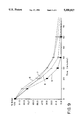
- FIGS. 8-9 are graphical representations of drying results utilizing a device which incorporates dual ceramic compositions of the invention.
- the improved ceramic materials of the invention are formed from a mixture of rare earth chromium oxides and a novel combination of stabilizing compounds of an alkaline earth aluminate spinel such as MgAl 2 O 4 , an alkaline earth chromate such as MgCrO 4 , and optional amounts of an alkaline earth zirconate such as CaZrO 3 .
- This unique combination of additives enables the rare earth chromium oxide ceramic compositions of the invention to possess surprisingly increased thermal, chemical and physical properties.
- This unique combination of stabilizing compounds moreover, enables the rare earth chromium oxide compounds to be heated at surprisingly high heating rates.
- electroconductive ceramic compositions formed of a mixture of rare earth chromium oxides of the formula RCrO 3 and a novel combination of stabilizing compounds is provided.
- R is any one of lanthanum, neodymium, and samarium, preferably lanthanum or neodymium, and most preferably lanthanum.
- the combination of stabilizing compounds includes alkaline earth spinels such as MgAl 2 O 4 , SrO:Al 2 O 3 , or CaO:Al 2 O 3 , most preferably MgAl 2 O 4 , an optional amount of alkaline earth zirconate or alkaline earth hafniate, preferably CaZrO 3 or CaHfO 3 , and an alkaline earth chromate such as MgCrO 4 , SrCrO 4 , or CaCrO 4 , and most preferably MgCrO 4 .
- This combination of additives may be present in an amount of about 1-35 weight percent, and most preferably about 1.5-26 weight percent of the overall rare earth chromium oxide ceramic composition.
- the rare earth chromium oxide ceramic materials of the invention are illustrated by the general composition below:
- the preparation of the chromium oxide and silica ceramic compositions of the invention is accomplished by ball milling components such as rare earth chromium oxides and stabilizer compounds in a plastic lined planet mill with Teflon balls to provide a finely ground powder.
- the powder is melted, ground, dried and pressed into shaped articles.
- the shaped articles then are sintered to provide a final product. Melting of these materials generally is accomplished under conditions which minimize the loss of oxygen from the formulated powder.
- the rare earth chromium oxide ceramic compositions can be melted at temperatures of about 2500° C.
- the silica based ceramic compositions typically can be melted at about 1900° C. Preferably, melting is accomplished in oxidizing atmospheres, most preferably air.
- Sintering of the rare earth chromium oxide compositions is performed in oxidizing atmospheres at temperatures up to about 1700° C., preferably at about 1600° C. for about 12 hours.
- Sintering of the silica based compositions is also performed in oxidizing atmospheres at temperatures up to about 1800° C., preferably at about 1500° C. for 12 hours.
- Furnaces suitable for sintering at these temperatures in oxidizing atmospheres are illustrated by furnaces that employ LaCrO 3 heating elements.
- the resultant articles are heated to high temperatures for extended time periods in oxidizing atmospheres such as at about 1500° C. to evaluate thermal, physical and mechanical properties such as compressive strength. Samples also are heated for about 20 hours at about 1600° C. to evaluate weight loss. Additional samples are metallized to evaluate specific resistance.
- Samples are evaluated to measure the maximum rate which the ceramic compositions of the invention may be heated.
- the maximum rate of heating of the samples is based on appearance of either surface cracks or internal melting and cracking.
- the results of these property measurements are presented in Tables 1-11. These properties show that the ceramic materials of the invention are useful in a variety of applications where rapid heating rates and property stability are important. For example, such materials may be employed in applications directed to low temperature drying and sterilization. Additional applications include high temperature heating elements, semiconductors, thermocouples, temperature detectors and the like.
- the improved properties of the ceramic compositions of the present invention are useful in devices such as dryers or sterilizers where such properties are beneficial for optimum operation.
- an appropriate quantity of IR must be generated for uniform exposure to the entire article.
- IR generated for sterilization of such articles must be sufficient to sterilize the relatively larger surfaces of the articles without overheating or deteriorating the relatively smaller surfaces or those portions of the article which are made of less IR resistant materials.
- the present invention utilizes a first transforming screen made of the rare earth chromium oxide ceramic material described above as formulation A, which screen is placed in between the source of radiation and the article to be sterilized, and a second screen placed with respect to the first screen as a refractor of IR therefrom and made from a ceramic material having the following composition:
- a sterilizer device 100 is illustrated in FIGS. 1-4.
- the device 100 includes an internal chamber which is accessible by a door 110 and into which is placed the articles to be sterilized.
- the appropriate controls 120 for the radiation sources and, if desired, the temperature of the chamber and a LED display 130, are provided in convenient locations on the front of the device.
- a tray 140 is provided to support the articles to be sterilized.
- energizable elements 150 Located in an upper portion of the chamber are a number of energizable elements 150. These elements may be halogen lamps or a heating coil 160 of a high resistance material placed in a ceramic, quartz glass and/or metal tube 170.
- these elements 150 are preferably provided with a concentric tube of a first ceramic material 180 for receiving and absorbing energy from the elements 150 and for emitting infrared radiation of one or more wavelengths, which radiation is subsequently directed toward the articles for sterilization thereof.
- This material 180 is preferably a ceramic material according to formulation A.
- a screen 190 of a second ceramic material preferably a ceramic material according to formulation B, is placed above the elements for receiving and absorbing infrared radiation from the first ceramic material, and for emitting infrared radiation of one or more wavelengths which radiation is different from that emitted by the first ceramic material.
- This second ceramic material is positioned within the chamber so that its emitted radiation is directed toward the articles for sterilization thereof.
- the ceramic compositions of the invention are also beneficial for use in drying devices. These devices have utility in a variety of applications, such as in the production of food products, plastics, ceramics, wood, bricks, leather, dishes, containers, pharmaceutical products and in other fields where it is necessary to have fast, efficient and qualitative drying with preservation of the main features of the objects that are to be dried.
- FIGS. 5-7 One drying device is shown in FIGS. 5-7, wherein the device includes a drying chamber which is similar in external appearance to device 100 of FIG. 1.
- a net or screen 210 is provided to support the objects 220 to be dried.
- this net is made of a stainless steel wire mesh of suitable gauge to retain the objects to be dried thereupon.
- a plurality of such nets may be included within the chamber of the device.
- energizable elements 230 Disposed throughout the chamber are a number of energizable elements 230, as shown in FIGS. 5 and 7. These elements may be halogen lamps or a heating coil 240 of a high resistance material placed in a ceramic, quartz glass and/or metal tube 250.
- a transforming screen or coating of mullite or another aluminosilicate which includes a supplement of formulation A in an amount of 0.5-4.0% by weight of the composition is included within the chamber, placed adjacent the energizable elements for receiving and absorbing infrared radiation and for emitting infrared radiation of one or more wavelengths.
- energizable elements as disclosed above which are covered by a layer of first and second ceramic materials.
- a first layer 260 of a ceramic composition such as formulation B
- a second layer 270 of a ceramic composition such as formulation A or a mixture of mullite with formulation A as defined above, is placed over the first layer 260.
- Preferred compositions for these ceramic layers are presented in the following examples.
- the size of the chamber may be varied as desired by one skilled in the art, provided that a substantial portion of the infrared radiation emitted from both the first and second ceramic materials can be directed to the articles to be sterilized or dried.
- these devices can be used in a continuous mode, whereby the energizable elements are arranged about a conveyor belt or other movable support which carries the objects to be sterilized to, through and away from the radiation.
- Examples 2-10 show the unexpected results obtainable with the ceramic compositions of the invention compared to a representative prior art ceramic composition (i.e., Example 1).
- a ceramic composition with the following weight percentage components which are outside of the percent ranges of the compositions of the invention is formulated as follows:
- Samples for evaluation of maximum heating rate are heated at a variety of rates. Cross-sections of these samples are inspected to identify surface cracks and internal melting. Samples heated at a rate of 5 K/min were found to be in good condition. Samples heated at a rate of 10 K/min showed cracking. As shown in Table 1, the properties of Control Example 1 given in column 1 therein are inferior to the properties of the ceramics disclosed in U.S. Pat. No. 3,475,352 given in column 6 of Table 1.
- control Example 1 The procedure of control Example 1 is followed with the exception that the ceramic composition employed corresponds to that of column 2 of Table 1.
- the resulting products have properties which surprisingly are superior to the properties of the products of U.S. Pat. No. 3,475,352 shown in column 6 of Table 1.
- control Example 1 The procedure of control Example 1 is followed with the exception that the ceramic composition corresponds to that of column 3 of Table 1. As shown in Table 1, the properties of the samples produced are surprisingly better than that of U.S. Pat. No. 3,475,352. Illustratively, the decrease in the compressive strength after about 60 hours of exposure at about 1500° C. is only 4.2 MPa. Further, the maximum heating rate is five times greater than that disclosed in U.S. Pat. No. 3,475,352.
- control Example 1 The procedure of control Example 1 is followed with the exception that the ceramic composition corresponds to Column 4 of Table 1. As shown in Table 1, the properties of the samples produced are better than those of U.S. Pat. No. 3,475,352 with the exception of specific resistance.
- control Example 1 The procedure of control Example 1 is followed with the exception that the ceramic composition corresponds to column 5 of Table 1.
- the increase in specific resistance of this example surprisingly is so great that the sample was unable to be heated to evaluate maximum heating rate.
- control Example 1 The procedure of control Example 1 is followed with the exception that the compositions shown in columns 1-5 of Tables 2 and 3 are employed. In the compositions of Table 2, minimal percentages of MgAl 2 O 4 are employed whereas in Table 3, maximal amounts MgAl 2 O 4 are employed. As can be seen from the data presented in Tables 2 and 3, the properties shown in columns 2-5 of Tables 1 and 2 exceed those of U.S. Pat. No. 3,475,352.
- control Example 1 The procedure of control Example 1 is followed with the exception that the compositions shown in columns 1-5 of Tables 4 and 5 are employed. In the compositions of Table 4, minimal amounts of YCrO 3 are employed whereas in Table 5 maximal amounts of YCrO 3 are employed. As shown in Tables 4 and 5, the properties of the inventive compositions shown in columns 2-5 exceed those of U.S. Pat. No. 3,475,352.
- control Example 1 The procedure of control Example 1 is followed with the exception that the compositions shown in columns 1-5 of Tables 6 and 7 are employed. In the compositions of Table 6, minimal amounts of MgCr 2 O 4 are employed whereas maximal amounts of MgCr 2 O 4 are employed in Table 7. As shown in Tables 6 and 7, the properties of the inventive compositions shown in columns 2-5 exceed those of U.S. Pat. No. 3,475,352.
- control Example 1 The procedure of control Example 1 is employed with the exception that the compositions shown in columns 1-5 of Tables 8 and 9 are employed. In the compositions of Table 8, minimal amounts of CeO 2 are employed whereas maximal amounts of CeO 2 are employed in Table 9. As shown in Tables 8 and 9, the properties of the inventive compositions shown in columns 2-5 exceed those of U.S. Pat. No. 3,475,352.
- control Example 1 The procedure of control Example 1 is employed with the exception that the compositions shown in Tables 10 and 11 are employed. In the compositions of Table 10, minimal amounts of CaZrO 3 are employed whereas maximal amounts of CaZrO 3 are employed in Table 11. As shown in columns 2-5 of Tables 10 and 11, the properties of the inventive compositions of Example 10 exceed those of U.S. Pat. No. 3,475,352.
- the invention surprisingly provides reductions in weight loss of up to three times more than that of the prior art.
- the invention further surprisingly provides a nine-fold decrease in the variation of compressive strength under pressure after exposure at about 1500° C. for about 60 hours.
- the invention moreover provides nearly an increase of 1.5 times the compressive strength and a five fold increase in the maximal rate of heating.
- Articles of medical instruments in need of sterilization were put into a chamber having the dimensions 310 ⁇ 175 ⁇ 100 mm.
- a source of IR radiation four halogen lamps were used, and these were uniformly distributed in the upper part of the chamber.
- the lamps are additionally covered by a layer of ceramic material of formulation A.
- the lamps was placed a screen prepared from the ceramic material of formulation B.
- the transforming layers begin to be heated and after a time of 1-1.5 min., the temperature of the transforming layers becomes stabilized due to thermal balance at the approximate level of 600 degrees C. In such way, the treatment of the medical instruments takes place through the IR radiation.
- Results of the sterilization tests were as follows. Various medical instruments such as syringes and needles, scarificators, scalpels and pincers were then exposed to IR at 125° C. using the sterilizing device of the invention for time periods of 1, 2, 3, 5, 10 and 15 minutes, respectively. Nine separate tests were conducted for each article at each time period. It was found that each of the articles was appropriately sterilized with no indication of bacteria or viruses.
- An object in need of drying is prepared in accordance with its type, for example vegetables and fruits could be washed, cleaned from any rotting parts, cut if necessary and then put into the chamber of the dryer described above and then exposed to IR radiation, where the IR radiation is produced by the action of radiation of a primary source into a transforming layer or screen of the ceramic material of formulation B.
- a primary source of radiation the energizable elements described above can be used.
- the drying process continues until the decrease of the product mass stops.
- the cell mass of the product is preserved under the drying process without destruction and/or alteration. This allows the preservation of most primary property and feature of the dried product, such as its nutritious properties or features, including color, taste, smell, etc. At same time the product is dried, it is also sterilized.
- the dried product When the dried product is placed into water, it takes about 15-25 minutes to re-absorb the lost water and restore its primary shape and condition, i.e. the volume, weight, taste, smell, etc.
- the ceramic layer of element (3) included the following composition:
- the ceramic layer of element (4) included 1% by weight of the ceramic material of formulation 2 of Table 1 with 99% by weight of mullite ("formulation D"), while the ceramic layer of element (5) included a first layer of the ceramic composition of formulation C, followed by a second layer of the ceramic material of formulation D.
- the maximum speed of the drying process is achieved by the consequential covering of the radiators with the two ceramic compositions (element (5)).
- the product being dried approaches a constant weight after about 40 minutes.
- Element (4) also produces a dried product after about 75 minutes.
- the ceramic layer of element (6) included the following composition:
- the ceramic layer of element (8) included 1% by weight of the ceramic material of formulation 4 of Table 11 with 99% by weight of mullite ("formulation F"), while the ceramic layer of element (9) included a first layer of the ceramic composition of formulation E, followed by a second layer of the ceramic material of formulation F.
- the maximum speed of the drying process is achieved by the consequential covering of the radiators with the two ceramic compositions (element (9)), with the product being dried approaching a constant weight after about 40 minutes.
- Element (8) also produces a dried product after about 75 minutes.
Abstract
Description
______________________________________
FORMULATION A
Component     Weight Percent
______________________________________
MgAl.sub.2 O.sub.4
              0.5-10
MgCrO.sub.4   1.0-15
CaZrO.sub.3    up to 10
YCrO.sub.3    up to 5
ZrO.sub.2     up to 5
CeO.sub.2     up to 1
LaCrO.sub.3   remainder
______________________________________
______________________________________
FORMULATION B
Component     Weight Percent
______________________________________
SiO.sub.2     10-28
Fe.sub.2 O.sub.3
              15-35
CaO           up to 15
Al.sub.2 O.sub.3
               up to 3.5
MgO           up to 3
CuO           up to 2
Cr.sub.2 O.sub.3
              Remainder
______________________________________
______________________________________
Component     Weight Percent
______________________________________
LaCrO.sub.3   98.55
MgCrO.sub.4   0.5
MgAl.sub.2 O.sub.4
              0.3
YCrO.sub.3    0.3
ZrO.sub.2     0.3
CeO.sub.2     0.05
CaZrO.sub.3   0.03
______________________________________
              TABLE 1
______________________________________
Components
and      Percentage of components, weight %
properties
         1       2       3     4     5      6.sup.3
______________________________________
MgAl.sub.2 O.sub.4
         0.3     0.5     3.0   10.0  12.0
YCrO.sub.3
         0.3     0.5     1.5   3.0   4.0
MgCr.sub.2 O.sub.4
         0.5     1.0     10.0  15.0  20.0
CeO.sub.2
         0.05    0.1     0.5   1.0   2.0
ZrO.sub.2
         0.3     0.5     3.0   5.0   6.0
CaZRO.sub.3
         0.03    0.05    0.3   0.5   0.6
LaCrO.sub.3
         BALANCE
Weight   1.2     0.5     0.2   0.3   1.0    0.55-
loss, %                                     0.6
Specific 292.1   116.0   7.7   873.4 2213.4 50-
resistance,                                 4800
(Ohm-cm)
σPa.sup.1
         72.6    96.3    144.1 120.1 115.6  96-
                                            135
σPa.sup.2
         18.4    71.4    140.3 33.2  26.2   10.2-
                                            16.1
Maximal  5       15      50    20    --     10
speed of
heating
K./min
______________________________________
 .sup. 1 Room Temperature Compressive Strength
 .sup.2 Compressive Strength after 60 hours exposure at 1500° C.
 .sup.3 Properties of U.S. Pat. No. 3,475,352
              TABLE 2
______________________________________
Components
and main Percentage of components, weight %
parameters
         1       2       3     4     5      6
______________________________________
MgAl.sub.2 O.sub.4
         0.5     0.5     0.5   0.5   0.5
YCrO.sub.3
         0.3     0.5     1.5   3.0   4.0
MgCr.sub.2 O.sub.4
         0.5     1.0     10.0  15.0  20.0
CeO.sub.2
         0.05    0.1     0.5   1.0   2.0
ZrO.sub.2
         0.3     0.5     3.0   5.0   6.0
CaZRO.sub.3
         0.03    0.05    0.3   0.5   0.6
LaCrO.sub.3
         BALANCE
Weight   1.0     0.5     0.2   0.3   1.0    0.55-
loss, %                                     0.6
Specific 304.8   116.0   7.4   672.3 1995.9 50-
resistance,                                 4800
(Ohm-cm)
σPa.sup.1
         74.2    96.3    136.2 118.1 110.4  96-
                                            135
σPa.sup.2
         18.7    71.4    130.5 33.1  25.1   10.2-
                                            16.1
Maximal  5       15      50    20    --     10
speed of
heating
K./min
______________________________________
 .sup.1 Room Temperature Compressive Strength
 .sup.2 Compressive Strength after 60 hours exposure at 1500° C.
 .sup.3 Properties of U.S. Pat. No. 3,475,352
              TABLE 3
______________________________________
Components
and main Percentage of components, weight %
parameters
         1       2       3     4     5      6
______________________________________
MgAl.sub.2 O.sub.4
         10.0    10.0    10.0  10.0  10.0
YCrO.sub.3
         0.3     0.5     1.5   3.0   4.0
MgCr.sub.2 O.sub.4
         0.5     1.0     10.0  15.0  20.0
CeO.sub.2
         0.05    0.1     0.5   1.0   2.0
ZrO.sub.2
         0.3     0.5     3.0   5.0   6.0
CaZRO.sub.3
         0.03    0.05    0.3   0.5   0.6
LaCrO.sub.3
         BALANCE
Weight   1.2     0.5     0.2   0.3   1.0    0.55-
loss, %                                     0.6
Specific 490.3   399.7   55.2  837.4 1857.8 50-
resistance,                                 4800
(Ohm-cm)
σPa.sup.1
         112.6   98.8    152.8 120.1 103.2  96-
                                            135
σPa.sup.2
         29.6    81.4    143.2 33.2  38.6   10.2-
                                            16.1
Maximal  5       15      50    20    --     10
speed of
heating
K./min
______________________________________
 .sup. 1 Room Temperature Compressive Strength
 .sup.2 Compressive Strength after 60 hours exposure at 1500° C.
 .sup.3 Properties of U.S. Pat. No. 3,475,352
              TABLE 4
______________________________________
Components
and main Percentage of components, weight %
parameters
         1       2       3     4     5      6
______________________________________
MgAl.sub.2 O.sub.4
         0.3     0.5     3.0   10.0  12.0
YCrO.sub.3
         0.5     0.5     0.5   0.5   0.5
MgCr.sub.2 O.sub.4
         0.5     1.0     10.0  15.0  20.0
CeO.sub.2
         0.05    0.1     0.5   1.0   2.0
ZrO.sub.2
         0.3     0.5     3.0   5.0   6.0
CaZRO.sub.3
         0.03    0.05    0.3   0.5   0.6
LaCrO.sub.3
         BALANCE
Weight   1.2     0.5     0.2   0.3   1.0    0.55-
loss, %                                     0.6
Specific 270.5   116.0   35.1  819.5 2035.7 50-
resistance,                                 4800
(Ohm-cm)
σPa.sup.1
         72.6    96.3    144.1 120.1 115.6  96-
                                            135
σPa.sup.2
         18.4    71.4    140.3 33.2  26.2   10.2-
                                            16.1
Maximal  5       15      50    20    --     10
speed of
heating
K./min
______________________________________
 .sup. 1 Room Temperature Compressive Strength
 .sup.2 Compressive Strength after 60 hours exposure at 1500° C.
 .sup.3 Properties of U.S. Pat. No. 3,475,352
              TABLE 5
______________________________________
Components
and main Percentage of components, weight %
parameters
         1       2       3     4     5      6
______________________________________
MgAl.sub.2 O.sub.4
         0.3     0.5     3.0   10.0  12.0
YCrO.sub.3
         3.0     3.0     3.0   3.0   3.0
MgCr.sub.2 O.sub.4
         0.5     1.0     10.0  15.0  20.0
CeO.sub.2
         0.05    0.1     0.5   1.0   2.0
ZrO.sub.2
         0.3     0.5     3.0   5.0   6.0
CaZRO.sub.3
         0.03    0.05    0.3   0.5   0.6
LaCrO.sub.3
         BALANCE
Weight   1.2     0.5     0.2   0.3   1.0    0.55-
loss, %                                     0.6
Specific 353.8   220.3   25.   873.4 2213.4 50-
resistance,                                 4800
(Ohm-cm)
σPa.sup.1
         82.7    93.7    121.2 120.1 125.8  96-
                                            135
σPa.sup.2
         19.9    62.8    87.3  33.2  28.7   10.2-
                                            16.1
Maximal  5       15      40    20    --     10
speed of
heating
K./min
______________________________________
 .sup. 1 Room Temperature Compressive Strength
 .sup.2 Compressive Strength after 60 hours exposure at 1500° C.
 .sup.3 Properties of U.S. Pat. No. 3,475,352
              TABLE 6
______________________________________
Components
and main Percentage of components, weight %
parameters
         1       2       3     4     5      6
______________________________________
MgAl.sub.2 O.sub.4
         0.3     0.5     3.0   10.0  12.0
YCrO.sub.3
         0.3     0.5     1.5   3.0   4.0
MgCr.sub.2 O.sub.4
         1.0     1.0     1.0   1.0   1.0
CeO.sub.2
         0.05    0.1     0.5   1.0   2.0
ZrO.sub.2
         0.3     0.5     3.0   5.0   6.0
CaZRO.sub.3
         0.03    0.05    0.3   0.5   0.6
LaCrO.sub.3
         BALANCE
Weight   1.2     0.5     0.2   0.3   1.0    0.55-
loss, %                                     0.6
Specific 188.5   116.0   18.0  867.1 2055.7 50-
resistance,                                 4800
(Ohm-cm)
σPa.sup.1
         92.5    96.3    117.8 102.3 98.7   96-
                                            135
σPa.sup.2
         37.4    51.4    60.3  21.1  13.1   10.2-
                                            16.1
Maximal  5       15      40    20    --     10
speed of
heating
K./min
______________________________________
 .sup.1 Room Temperature Compressive Strength
 .sup.2 Compressive Strength after 60 hours exposure at 1500° C.
 .sup.3 Properties of U.S. Pat. No. 3,475,352
              TABLE 7
______________________________________
Components
and main Percentage of components, weight %
parameters
         1       2       3     4     5      6
______________________________________
MgAl.sub.2 O.sub.4
         0.3     0.5     3.0   10.0  12.0
YCrO.sub.3
         0.3     0.5     1.5   3.0   4.0
MgCr.sub.2 O.sub.4
         15.0    15.0    15.0  15.0  15.0
CeO.sub.2
         0.05    0.1     0.5   1.0   2.0
ZrO.sub.2
         0.3     0.5     3.0   5.0   6.0
CaZRO.sub.3
         0.03    0.05    0.3   0.5   0.6
LaCrO.sub.3
         BALANCE
Weight   1.2     0.5     0.2   0.3   1.0    0.55-
loss, %                                     0.6
Specific 282.0   199.0   22.1  873.4 2076.5 50-
resistance,                                 4800
(Ohm-cm)
σPa.sup.1
         87.3    96.3    98.1  120.1 105.3  96-
                                            135
σPa.sup.2
         81.2    90.6    90.3  33.2  25.1   10.2-
                                            16.1
Maximal  5       15      30    20    --     10
speed of
heating
K./min
______________________________________
 .sup. 1 Room Temperature Compressive Strength
 .sup.2 Compressive Strength after 60 hours exposure at 1500° C.
 .sup.3 Properties of U.S. Pat. No. 3,475,352
              TABLE 8
______________________________________
Components
and main Percentage of components, weight %
parameters
         1       2       3     4     5      6
______________________________________
MgAl.sub.2 O.sub.4
         0.3     0.5     3.0   10.0  12.0
YCrO.sub.3
         0.3     0.5     1.5   3.0   4.0
MgCr.sub.2 O.sub.4
         0.5     1.0     10.0  15.0  20.0
CeO.sub.2
         0.1     0.1     0.1   0.1   0.1
ZrO.sub.2
         0.3     0.5     3.0   5.0   6.0
CaZRO.sub.3
         0.03    0.05    0.3   0.5   0.6
LaCrO.sub.3
         BALANCE
Weight   1.2     0.5     0.2   0.3   1.0    0.55-
loss, %                                     0.6
Specific 297.0   116.0   8.1   862.1 2098.9 50-
resistance,                                 4800
(Ohm-cm)
σPa.sup.1
         72.1    96.3    144.0 120.3 115.0  96-
                                            135
σPa.sup.2
         18.4    71.4    140.3 33.2  26.2   10.2-
                                            16.1
Maximal  10      15      40    20    --     10
speed of
heating
K./min
______________________________________
 .sup. 1 Room Temperature Compressive Strength
 .sup.2 Compressive Strength after 60 hours exposure at 1500° C.
 .sup.3 Properties of U.S. Pat. No. 3,475,352
              TABLE 9
______________________________________
Components
and main Percentage of components, weight %
parameters
         1       2       3     4     5      6
______________________________________
MgAl.sub.2 O.sub.4
         0.3     0.5     3.0   10.0  12.0
YCrO.sub.3
         0.3     0.5     1.5   3.0   4.0
MgCr.sub.2 O.sub.4
         0.5     1.0     10.0  15.0  20.0
CeO.sub.2
         1.0     1.0     1.0   1.0   1.0
ZrO.sub.2
         0.3     0.5     3.0   5.0   6.0
CaZRO.sub.3
         0.03    0.05    0.3   0.5   0.6
LaCrO.sub.3
         BALANCE
Weight   1.2     0.5     0.2   0.3   1.0    0.55-
loss, %                                     0.6
specific 288.0   110.2   10.6  873.4 2398.1 50-
resistance,                                 4800
(Ohm-cm)
σPa.sup.1
         71.9    89.3    134.5 120.1 107.6  96-
                                            135
σPa.sup.2
         16.7    67.5    112.4 33.2  21.5   10.2-
                                            16.1
Maximal  5       15      40    20    --     10
speed of
heating
K./min
______________________________________
 .sup. 1 Room Temperature Compressive Strength
 .sup.2 Compressive Strength after 60 hours exposure at 1500° C.
 .sup.3 Properties of U.S. Pat. No. 3,475,352
              TABLE 10
______________________________________
Components
and main Percentage of components, weight %
parameters
         1       2       3     4     5      6
______________________________________
MgAl.sub.2 O.sub.4
         0.3     0.5     3.0   10.0  12.0
YCrO.sub.3
         0.3     0.5     1.5   3.0   4.0
MgCr.sub.2 O.sub.4
         0.5     1.0     10.0  15.0  20.0
CeO.sub.2
         0.05    0.1     0.5   1.0   2.0
ZrO.sub.2
         0.3     0.5     3.0   5.0   6.0
CaZRO.sub.3
         0.05    0.05    0.05  0.05   0.05
LaCrO.sub.3
         BALANCE
Weight   0.9     0.5     0.3   0.4   1.0    0.55-
loss, %                                     0.6
Specific 348.0   116.0   6.6   717.8 1857.0 50-
resistance,                                 4800
(Ohm-cm)
σPa.sup.1
         92.6    96.3    123.1 103.3 89.8   96-
                                            135
σPa.sup.2
         21.3    71.4    101.6 36.9  32.2   10.2-
                                            16.1
Maximal  5       15      50    20    --     10
speed of
heating
K./min
______________________________________
  .sup.1 Room Temperature Compressive Strength
 .sup.2 Compressive Strength after 60 hours exposure at 1500° C.
 .sup.3 Properties of U.S. Pat. No. 3,475,352
              TABLE 11
______________________________________
Components
and main Percentage of components, weight %
parameters
         1       2       3     4     5      6
______________________________________
MgAl.sub.2 O.sub.4
         0.3     0.5     3.0   10.0  12.0
YCrO.sub.3
         0.3     0.5     1.5   3.0   4.0
MgCr.sub.2 O.sub.4
         0.5     1.0     10.0  15.0  20.0
CeO.sub.2
         0.05    0.1     0.5   1.0   2.0
ZrO.sub.2
         0.3     0.5     3.0   5.0   6.0
CaZRO.sub.3
         0.5     0.5     0.5   0.5   0.5
LaCrO.sub.3
         BALANCE
Weight   0.3     0.3     0.2   0.3   1.0    0.55-
loss, %                                     0.6
Specific 396.0   275.1   54.0  873.4 1985.0 50-
resistance,                                 4800
(Ohm-cm)
σPa.sup.1
         96.6    112.3   152.1 120.1 109.7  96-
                                            135
σPa.sup.2
         16.2    61.2    121.4 33.2  30.2   10.2-
                                            16.1
Maximal  5       15      30    20    --     10
speed of
heating
K./min
______________________________________
 .sup. 1 Room Temperature Compressive Strength
 .sup.2 Compressive Strength after 60 hours exposure at 1500° C.
 .sup.3 Properties of U.S. Pat. No. 3,475,352
______________________________________
Formulation C
Component     Weight Percent
______________________________________
Fe.sub.2 O.sub.3
              28
SiO.sub.2     17
CaO           5.5
Al.sub.2 O.sub.3
              2.5
MgO           2
CuO           0.3
Cr.sub.2 O.sub.3
              44.7
______________________________________
______________________________________
Formulation E
Component     Weight Percent
______________________________________
Fe.sub.2 O.sub.3
              35
SiO.sub.2     28
CaO           15
Al.sub.2 O.sub.3
              3.5
MgO           3
CuO           2
Cr.sub.2 O.sub.3
              13.5
______________________________________
Claims (23)
Priority Applications (10)
| Application Number | Priority Date | Filing Date | Title |
|---|---|---|---|
| US07/900,228 US5350927A (en) | 1992-06-17 | 1992-06-17 | Radiation emitting ceramic materials and devices containing same |
| US07/962,372 US5472720A (en) | 1992-06-17 | 1992-10-16 | Treatment of materials with infrared radiation |
| EP93916598A EP0700572A1 (en) | 1992-06-17 | 1993-06-16 | Radiation emitting ceramic materials, devices containing same and methods of use thereof |
| MYPI93001173A MY111062A (en) | 1992-06-17 | 1993-06-16 | Radiotion emitting ceramic materials, devices containing same and methods of use thereof |
| AU46396/93A AU4639693A (en) | 1992-06-17 | 1993-06-16 | Radiation emitting ceramic materials, devices containing same and methods of use thereof |
| MX9303608A MX9303608A (en) | 1992-06-17 | 1993-06-16 | CERAMIC MATERIALS RADIATION EMITTERS, DEVICES CONTAINING THE SAME AND METHODS FOR USING THEM |
| PCT/US1993/005818 WO1993026011A1 (en) | 1992-06-17 | 1993-06-16 | Radiation emitting ceramic materials, devices containing same and methods of use thereof |
| CA002138407A CA2138407A1 (en) | 1992-06-17 | 1993-06-16 | Radiation emitting ceramic materials, devices containing same, and methods of use thereof |
| CN93109026.1A CN1083455A (en) | 1992-06-17 | 1993-06-17 | Send the radiating stupalith, contain the equipment of this pottery and their using method |
| US08/479,420 US5707911A (en) | 1992-06-17 | 1995-06-06 | Infrared radiation generating ceramic compositions |
Applications Claiming Priority (1)
| Application Number | Priority Date | Filing Date | Title |
|---|---|---|---|
| US07/900,228 US5350927A (en) | 1992-06-17 | 1992-06-17 | Radiation emitting ceramic materials and devices containing same |
Related Child Applications (1)
| Application Number | Title | Priority Date | Filing Date |
|---|---|---|---|
| US07/962,372 Continuation-In-Part US5472720A (en) | 1992-06-17 | 1992-10-16 | Treatment of materials with infrared radiation |
Publications (1)
| Publication Number | Publication Date |
|---|---|
| US5350927A true US5350927A (en) | 1994-09-27 |
Family
ID=25412197
Family Applications (1)
| Application Number | Title | Priority Date | Filing Date |
|---|---|---|---|
| US07/900,228 Expired - Fee Related US5350927A (en) | 1992-06-17 | 1992-06-17 | Radiation emitting ceramic materials and devices containing same |
Country Status (1)
| Country | Link |
|---|---|
| US (1) | US5350927A (en) |
Cited By (20)
| Publication number | Priority date | Publication date | Assignee | Title |
|---|---|---|---|---|
| US5736829A (en) * | 1994-08-02 | 1998-04-07 | Performance Controls, Inc. | High-speed constant-horsepower motor |
| US5823099A (en) * | 1998-03-18 | 1998-10-20 | Ko; Li-Sheng | Grill |
| WO1999042141A1 (en) * | 1998-02-20 | 1999-08-26 | Rustam Rakhimov | Method for sterilizing materials and articles and a device for implementing the same |
| US6114181A (en) * | 1998-08-05 | 2000-09-05 | International Business Machines Corporation | Pre burn-in thermal bump card attach simulation to enhance reliability |
| US6322362B1 (en) | 1998-03-26 | 2001-11-27 | Allan G. Holms | Dental instrument |
| DE10217011A1 (en) * | 2002-04-16 | 2003-11-13 | Ibt Infrabio Tech Gmbh | Emitter for infrared radiation of biological material |
| EP1482767A1 (en) * | 2003-05-27 | 2004-12-01 | Whirlpool Corporation | Microwave oven having a browning device |
| DE10345109A1 (en) * | 2003-09-26 | 2005-05-04 | Ibt Infrabio Tech Gmbh | Heating element for food oven converts contact heat, convection heat and radiation heat into infrared heating emissions |
| US20050121630A1 (en) * | 2003-12-03 | 2005-06-09 | Michael Arndt | Micromechanical infrared source |
| US20050147641A1 (en) * | 2004-01-02 | 2005-07-07 | Qi Yu | Plastic water and beverage bottle and manufacturing process thereof |
| US20060032846A1 (en) * | 2004-07-27 | 2006-02-16 | Dieter Haas | Infrared heating element and a substrate type vacuum chamber, particularly for vacuum coating facilities |
| EP1631121A1 (en) * | 2004-07-27 | 2006-03-01 | Applied Films GmbH & Co. KG | Infrared heating element and vacuum chamber with substrate heating, in particular for vacuum coating instalations |
| US20090003808A1 (en) * | 2007-06-30 | 2009-01-01 | Brooke Scott A | Ecowave 1.2 |
| US20100072406A1 (en) * | 2007-11-09 | 2010-03-25 | Canon Kabushiki Kaisha | Glass composition for ultraviolet light and optical device using the same |
| DE102009059295A1 (en) * | 2009-12-23 | 2011-06-30 | E-education GmbH, 65824 | Living room heater, has upper surface region that is smaller than another upper surface region, and radiation source emitting electromagnetic radiation with wave length in living room in latter upper surface region |
| WO2018027034A1 (en) * | 2016-08-03 | 2018-02-08 | Schott Gemtron Corp. | Oven having a dielectrically coated glass substrate that absorbs electromagnetic radiation and emits heat radiation |
| US20180243859A1 (en) * | 2017-02-28 | 2018-08-30 | Rolls-Royce Plc | Apparatus and methods for providing thermal energy to an article |
| US10591652B2 (en) | 2015-11-20 | 2020-03-17 | Schott Gemtron Corp. | Multi-layer coated glass substrate |
| US11472964B2 (en) | 2015-10-27 | 2022-10-18 | Gemtron Corporation | Coating compositions for glass substrates |
| CN116768651A (en) * | 2023-06-26 | 2023-09-19 | 湖北中烟工业有限责任公司 | Glaze, heating element, preparation method thereof and heating smoking set |
Citations (34)
| Publication number | Priority date | Publication date | Assignee | Title |
|---|---|---|---|---|
| US3284217A (en) * | 1964-12-21 | 1966-11-08 | Harbison Walker Refractories | Basic refractory |
| US3475352A (en) * | 1965-11-03 | 1969-10-28 | Commissariat Energie Atomique | Electrically conductive ceramic material |
| US3574142A (en) * | 1968-01-24 | 1971-04-06 | Commissariat Energie Atomique | Ceramic material for magnetohydrodynamic generator electrode |
| US3585390A (en) * | 1968-02-07 | 1971-06-15 | Tadashi Ishikawa | Zirconia ceramics and infrared ray radiation elements utilizing the same |
| US3625717A (en) * | 1968-04-29 | 1971-12-07 | Avco Corp | Spray coating compositions |
| US3730911A (en) * | 1970-10-05 | 1973-05-01 | Commissariat A I En Atomique | Heating element comprising lanthanum chromite and oxidation-resistant silicon compound |
| JPS499494A (en) * | 1972-05-26 | 1974-01-28 | ||
| JPS4988916A (en) * | 1972-12-27 | 1974-08-26 | ||
| US4000983A (en) * | 1973-07-26 | 1977-01-04 | Vladimir Ilich Alexandrov | Metal-ceramic |
| US4045375A (en) * | 1975-06-20 | 1977-08-30 | Koshi Arita | Highly electron-conductive composition |
| US4101454A (en) * | 1975-01-10 | 1978-07-18 | Texas Instruments Incorporated | Ceramic semiconductors |
| US4110260A (en) * | 1975-09-25 | 1978-08-29 | Tokyo Denki Kagaku Kogyo Kabushiki Kaisha (Tdk Electronics Co., Ltd.) | Electroconductive composite ceramics |
| GB1527955A (en) * | 1977-02-25 | 1978-10-11 | Mitsui Shipbuilding Eng | Catalyst and process for gasification of hydrocarbons |
| US4141743A (en) * | 1977-10-31 | 1979-02-27 | Dresser Industries, Inc. | Thermal spray powdered composite |
| US4330630A (en) * | 1980-03-14 | 1982-05-18 | Societe Europeenne Des Produits Refractaires | Fused cast refractory compositions and glass melting furnaces incorporating them |
| US4551616A (en) * | 1983-07-07 | 1985-11-05 | Thorn Emi Domestic Appliances Limited | Heating apparatus |
| US4551617A (en) * | 1983-06-15 | 1985-11-05 | Thorn Emi Domestic Appliances Limited | Heating apparatus |
| US4568848A (en) * | 1974-11-25 | 1986-02-04 | Murata Manufacturing Co, Ltd. | Acoustic surface wave devices containing piezoelectric ceramics |
| USRE32449E (en) * | 1983-06-16 | 1987-06-30 | Max-Planck-Gesellschaft Zur Forderung Der Wissenschaften E.V | Ceramic body of zirconium dioxide (ZrO2) and method for its preparation |
| USH302H (en) * | 1985-07-01 | 1987-07-07 | The United States Of America As Represented By The United States Department Of Energy | Ceramics containing dispersants for improved fracture toughness |
| US4774415A (en) * | 1986-01-23 | 1988-09-27 | Fresenius Ag | Device for sterilization of a hose coupling device in the connected condition |
| US4776895A (en) * | 1987-06-02 | 1988-10-11 | Quantum Group, Inc. | Multiband emitter matched to multilayer photovoltaic collector |
| JPH01150527A (en) * | 1987-12-08 | 1989-06-13 | Seiji Asai | Far infrared radiation resin molding |
| US4855265A (en) * | 1988-04-04 | 1989-08-08 | Corning Incorporated | High temperature low thermal expansion ceramic |
| US4864104A (en) * | 1982-12-24 | 1989-09-05 | Thorn Emi Patents Limited | Heating assembly using tungsten-halogen lamps |
| JPH01227376A (en) * | 1988-03-07 | 1989-09-11 | Tokai Konetsu Kogyo Co Ltd | Far infrared-ray heater |
| US4902876A (en) * | 1987-10-21 | 1990-02-20 | U.S. Philips Corp. | Electrical cooking apparatus |
| JPH02110137A (en) * | 1988-10-20 | 1990-04-23 | Nichinetsu Kogyo Kk | Food packaging film |
| US5006489A (en) * | 1988-09-07 | 1991-04-09 | Tungsram Reszvenytarsasag | Soldering enamel for preparing an end seal of a ceramic discharge envelope of a discharge lamp |
| US5057478A (en) * | 1989-02-21 | 1991-10-15 | Sakai Chemical Industry Co., Ltd. | Method of producing a composite material comprising a perovskite complex compound having an α-olefin polymer deposited thereon |
| US5104830A (en) * | 1989-06-21 | 1992-04-14 | Ceramiques Et Composites | Composite shaped articles comprising reinforced glass-ceramic matrices |
| JPH04131013A (en) * | 1990-09-25 | 1992-05-01 | Matsushita Electric Works Ltd | Preservation house for vegetable and fruits |
| US5130281A (en) * | 1990-07-10 | 1992-07-14 | Murata Manufacturing Co., Ltd. | Dielectric ceramic compositions and manufacturing method of dielectric ceramics |
| US5195165A (en) * | 1989-05-18 | 1993-03-16 | Matsushita Electric Industrial Co., Ltd. | Quartz tube heat generator with catalytic coating |
-
1992
- 1992-06-17 US US07/900,228 patent/US5350927A/en not_active Expired - Fee Related
Patent Citations (35)
| Publication number | Priority date | Publication date | Assignee | Title |
|---|---|---|---|---|
| US3284217A (en) * | 1964-12-21 | 1966-11-08 | Harbison Walker Refractories | Basic refractory |
| US3475352A (en) * | 1965-11-03 | 1969-10-28 | Commissariat Energie Atomique | Electrically conductive ceramic material |
| US3574142A (en) * | 1968-01-24 | 1971-04-06 | Commissariat Energie Atomique | Ceramic material for magnetohydrodynamic generator electrode |
| US3585390A (en) * | 1968-02-07 | 1971-06-15 | Tadashi Ishikawa | Zirconia ceramics and infrared ray radiation elements utilizing the same |
| US3625717A (en) * | 1968-04-29 | 1971-12-07 | Avco Corp | Spray coating compositions |
| US3730911A (en) * | 1970-10-05 | 1973-05-01 | Commissariat A I En Atomique | Heating element comprising lanthanum chromite and oxidation-resistant silicon compound |
| JPS499494A (en) * | 1972-05-26 | 1974-01-28 | ||
| JPS4988916A (en) * | 1972-12-27 | 1974-08-26 | ||
| US4000983A (en) * | 1973-07-26 | 1977-01-04 | Vladimir Ilich Alexandrov | Metal-ceramic |
| US4568848A (en) * | 1974-11-25 | 1986-02-04 | Murata Manufacturing Co, Ltd. | Acoustic surface wave devices containing piezoelectric ceramics |
| US4101454A (en) * | 1975-01-10 | 1978-07-18 | Texas Instruments Incorporated | Ceramic semiconductors |
| US4045375A (en) * | 1975-06-20 | 1977-08-30 | Koshi Arita | Highly electron-conductive composition |
| US4110260A (en) * | 1975-09-25 | 1978-08-29 | Tokyo Denki Kagaku Kogyo Kabushiki Kaisha (Tdk Electronics Co., Ltd.) | Electroconductive composite ceramics |
| GB1527955A (en) * | 1977-02-25 | 1978-10-11 | Mitsui Shipbuilding Eng | Catalyst and process for gasification of hydrocarbons |
| US4141743A (en) * | 1977-10-31 | 1979-02-27 | Dresser Industries, Inc. | Thermal spray powdered composite |
| US4330630A (en) * | 1980-03-14 | 1982-05-18 | Societe Europeenne Des Produits Refractaires | Fused cast refractory compositions and glass melting furnaces incorporating them |
| US4864104A (en) * | 1982-12-24 | 1989-09-05 | Thorn Emi Patents Limited | Heating assembly using tungsten-halogen lamps |
| US4864104B1 (en) * | 1982-12-24 | 1993-03-02 | Thorn Emi Patents Ltd | |
| US4551617A (en) * | 1983-06-15 | 1985-11-05 | Thorn Emi Domestic Appliances Limited | Heating apparatus |
| USRE32449E (en) * | 1983-06-16 | 1987-06-30 | Max-Planck-Gesellschaft Zur Forderung Der Wissenschaften E.V | Ceramic body of zirconium dioxide (ZrO2) and method for its preparation |
| US4551616A (en) * | 1983-07-07 | 1985-11-05 | Thorn Emi Domestic Appliances Limited | Heating apparatus |
| USH302H (en) * | 1985-07-01 | 1987-07-07 | The United States Of America As Represented By The United States Department Of Energy | Ceramics containing dispersants for improved fracture toughness |
| US4774415A (en) * | 1986-01-23 | 1988-09-27 | Fresenius Ag | Device for sterilization of a hose coupling device in the connected condition |
| US4776895A (en) * | 1987-06-02 | 1988-10-11 | Quantum Group, Inc. | Multiband emitter matched to multilayer photovoltaic collector |
| US4902876A (en) * | 1987-10-21 | 1990-02-20 | U.S. Philips Corp. | Electrical cooking apparatus |
| JPH01150527A (en) * | 1987-12-08 | 1989-06-13 | Seiji Asai | Far infrared radiation resin molding |
| JPH01227376A (en) * | 1988-03-07 | 1989-09-11 | Tokai Konetsu Kogyo Co Ltd | Far infrared-ray heater |
| US4855265A (en) * | 1988-04-04 | 1989-08-08 | Corning Incorporated | High temperature low thermal expansion ceramic |
| US5006489A (en) * | 1988-09-07 | 1991-04-09 | Tungsram Reszvenytarsasag | Soldering enamel for preparing an end seal of a ceramic discharge envelope of a discharge lamp |
| JPH02110137A (en) * | 1988-10-20 | 1990-04-23 | Nichinetsu Kogyo Kk | Food packaging film |
| US5057478A (en) * | 1989-02-21 | 1991-10-15 | Sakai Chemical Industry Co., Ltd. | Method of producing a composite material comprising a perovskite complex compound having an α-olefin polymer deposited thereon |
| US5195165A (en) * | 1989-05-18 | 1993-03-16 | Matsushita Electric Industrial Co., Ltd. | Quartz tube heat generator with catalytic coating |
| US5104830A (en) * | 1989-06-21 | 1992-04-14 | Ceramiques Et Composites | Composite shaped articles comprising reinforced glass-ceramic matrices |
| US5130281A (en) * | 1990-07-10 | 1992-07-14 | Murata Manufacturing Co., Ltd. | Dielectric ceramic compositions and manufacturing method of dielectric ceramics |
| JPH04131013A (en) * | 1990-09-25 | 1992-05-01 | Matsushita Electric Works Ltd | Preservation house for vegetable and fruits |
Non-Patent Citations (2)
| Title |
|---|
| Slack, G. A., "Advanced Materials for Optical Windows", GE Res. Rept. No. 79CRD071, Jun. 1979. |
| Slack, G. A., Advanced Materials for Optical Windows , GE Res. Rept. No. 79CRD071, Jun. 1979. * |
Cited By (26)
| Publication number | Priority date | Publication date | Assignee | Title |
|---|---|---|---|---|
| US5736829A (en) * | 1994-08-02 | 1998-04-07 | Performance Controls, Inc. | High-speed constant-horsepower motor |
| WO1999042141A1 (en) * | 1998-02-20 | 1999-08-26 | Rustam Rakhimov | Method for sterilizing materials and articles and a device for implementing the same |
| US5823099A (en) * | 1998-03-18 | 1998-10-20 | Ko; Li-Sheng | Grill |
| US6322362B1 (en) | 1998-03-26 | 2001-11-27 | Allan G. Holms | Dental instrument |
| US6114181A (en) * | 1998-08-05 | 2000-09-05 | International Business Machines Corporation | Pre burn-in thermal bump card attach simulation to enhance reliability |
| DE10217011A1 (en) * | 2002-04-16 | 2003-11-13 | Ibt Infrabio Tech Gmbh | Emitter for infrared radiation of biological material |
| EP1482767A1 (en) * | 2003-05-27 | 2004-12-01 | Whirlpool Corporation | Microwave oven having a browning device |
| DE10345109A1 (en) * | 2003-09-26 | 2005-05-04 | Ibt Infrabio Tech Gmbh | Heating element for food oven converts contact heat, convection heat and radiation heat into infrared heating emissions |
| US7279692B2 (en) * | 2003-12-03 | 2007-10-09 | Robert Bosch Gmbh | Micromechanical infrared source |
| US20050121630A1 (en) * | 2003-12-03 | 2005-06-09 | Michael Arndt | Micromechanical infrared source |
| US20050147641A1 (en) * | 2004-01-02 | 2005-07-07 | Qi Yu | Plastic water and beverage bottle and manufacturing process thereof |
| US20060032846A1 (en) * | 2004-07-27 | 2006-02-16 | Dieter Haas | Infrared heating element and a substrate type vacuum chamber, particularly for vacuum coating facilities |
| EP1631121A1 (en) * | 2004-07-27 | 2006-03-01 | Applied Films GmbH & Co. KG | Infrared heating element and vacuum chamber with substrate heating, in particular for vacuum coating instalations |
| US8295690B2 (en) * | 2007-06-30 | 2012-10-23 | Brooke Scott A | Infrared heating mechanism and system |
| US20090003808A1 (en) * | 2007-06-30 | 2009-01-01 | Brooke Scott A | Ecowave 1.2 |
| US20100072406A1 (en) * | 2007-11-09 | 2010-03-25 | Canon Kabushiki Kaisha | Glass composition for ultraviolet light and optical device using the same |
| US7935947B2 (en) * | 2007-11-09 | 2011-05-03 | Canon Kabushiki Kaisha | Glass composition for ultraviolet light and optical device using the same |
| DE102009059295A1 (en) * | 2009-12-23 | 2011-06-30 | E-education GmbH, 65824 | Living room heater, has upper surface region that is smaller than another upper surface region, and radiation source emitting electromagnetic radiation with wave length in living room in latter upper surface region |
| DE102009059295B4 (en) * | 2009-12-23 | 2013-04-25 | Diospharma Co., Ltd. | Space heater using a laser |
| US11472964B2 (en) | 2015-10-27 | 2022-10-18 | Gemtron Corporation | Coating compositions for glass substrates |
| US10591652B2 (en) | 2015-11-20 | 2020-03-17 | Schott Gemtron Corp. | Multi-layer coated glass substrate |
| WO2018027034A1 (en) * | 2016-08-03 | 2018-02-08 | Schott Gemtron Corp. | Oven having a dielectrically coated glass substrate that absorbs electromagnetic radiation and emits heat radiation |
| US11268704B2 (en) | 2016-08-03 | 2022-03-08 | Schott Ag | Oven having a dielectrically coated glass substrate that absorbs electromagnetic radiation and emits heat radiation into the oven cavity |
| US20180243859A1 (en) * | 2017-02-28 | 2018-08-30 | Rolls-Royce Plc | Apparatus and methods for providing thermal energy to an article |
| US10758996B2 (en) * | 2017-02-28 | 2020-09-01 | Rolls-Royce Plc | Apparatus and methods for providing thermal energy to an article |
| CN116768651A (en) * | 2023-06-26 | 2023-09-19 | 湖北中烟工业有限责任公司 | Glaze, heating element, preparation method thereof and heating smoking set |
Similar Documents
| Publication | Publication Date | Title |
|---|---|---|
| US5350927A (en) | Radiation emitting ceramic materials and devices containing same | |
| US5472720A (en) | Treatment of materials with infrared radiation | |
| KR960007375B1 (en) | Far-infrared radiator | |
| US3783220A (en) | Method and apparatus for browning exterior surfaces of foodstuff in an electronic range | |
| US3585390A (en) | Zirconia ceramics and infrared ray radiation elements utilizing the same | |
| JP2008116058A (en) | Technological development for carrying out cooking and chemical reaction, chemical synthesis, metal working, metal crystallization, metal sintering and metallurgy by heating pottery with microwave for converting into far infrared or infrared wave radiation and improving heat efficiency | |
| US5542194A (en) | Silicon carbide body for radiating far-infrared radiation, drying apparatus including the body, and firing apparatus including the body | |
| KR930000003B1 (en) | Far-ir radiating ceramic composition and processing method therefore | |
| EP0994827B1 (en) | Infrared radiation emitting ceramic material | |
| JPS59213771A (en) | Coating composition for radiating far infrared ray | |
| JP2008162866A (en) | Composite ceramic material for infrared emission, method for producing the same, member for cookware and rice cooker | |
| US20200170765A1 (en) | Process For The Production Of A Dental Restoration | |
| WO1998012491A1 (en) | Device and process for dehydration | |
| KR100414467B1 (en) | THE GLAZE EMITTiNG FAR INFRARED RAYS | |
| JPH05258857A (en) | Microwave oven cooking apparatus | |
| KR940005085B1 (en) | Radiate substance of farinfrared rays | |
| KR20030033196A (en) | Ceramic pyrogen composition absorbing microwave and method for manufacturing the same | |
| JPH064506B2 (en) | Far infrared emitting ceramics | |
| WO1999036372A1 (en) | Ceramic material | |
| WO1999036373A1 (en) | Ceramic material | |
| KR20000059947A (en) | Microwave-heated hot pack material and mathod thereof | |
| WO1999042141A1 (en) | Method for sterilizing materials and articles and a device for implementing the same | |
| JPH0321501B2 (en) | ||
| JPS6411168A (en) | Production of coating compound | |
| JPH067508B2 (en) | Far-infrared radiator for heating and heat dissipation |
Legal Events
| Date | Code | Title | Description |
|---|---|---|---|
| AS | Assignment |
Owner name: MITECH SCIENTIFIC CORPORATION A DE CORP., NEW J Free format text: ASSIGNMENT OF ASSIGNORS INTEREST.;ASSIGNOR:RAKHIMOV, ROUSTAM K.;REEL/FRAME:006267/0023 Effective date: 19920617 |
|
| AS | Assignment |
Owner name: MITECH SCIENTIFIC CORPORATION A DE CORP., NEW J Free format text: ASSIGNMENT OF ASSIGNORS INTEREST.;ASSIGNORS:RAKHIMOV, ROUSTAM K.;KIM, ELENA V.;REEL/FRAME:006267/0021 Effective date: 19920617 |
|
| FPAY | Fee payment |
Year of fee payment: 4 |
|
| SULP | Surcharge for late payment | ||
| FEPP | Fee payment procedure |
Free format text: PAT HOLDER NO LONGER CLAIMS SMALL ENTITY STATUS, ENTITY STATUS SET TO UNDISCOUNTED (ORIGINAL EVENT CODE: STOL); ENTITY STATUS OF PATENT OWNER: LARGE ENTITY |
|
| FPAY | Fee payment |
Year of fee payment: 8 |
|
| REMI | Maintenance fee reminder mailed | ||
| LAPS | Lapse for failure to pay maintenance fees | ||
| STCH | Information on status: patent discontinuation |
Free format text: PATENT EXPIRED DUE TO NONPAYMENT OF MAINTENANCE FEES UNDER 37 CFR 1.362 |
|
| FP | Lapsed due to failure to pay maintenance fee |
Effective date: 20060927 |