US5374856A - Timer motor incremental drive - Google Patents
Timer motor incremental drive Download PDFInfo
- Publication number
- US5374856A US5374856A US07/975,055 US97505592A US5374856A US 5374856 A US5374856 A US 5374856A US 97505592 A US97505592 A US 97505592A US 5374856 A US5374856 A US 5374856A
- Authority
- US
- United States
- Prior art keywords
- camstack
- cam
- switch
- motor
- motor control
- Prior art date
- Legal status (The legal status is an assumption and is not a legal conclusion. Google has not performed a legal analysis and makes no representation as to the accuracy of the status listed.)
- Expired - Lifetime
Links
Images


Classifications
-
- H—ELECTRICITY
- H01—ELECTRIC ELEMENTS
- H01H—ELECTRIC SWITCHES; RELAYS; SELECTORS; EMERGENCY PROTECTIVE DEVICES
- H01H43/00—Time or time-programme switches providing a choice of time-intervals for executing one or more switching actions and automatically terminating their operations after the programme is completed
- H01H43/10—Time or time-programme switches providing a choice of time-intervals for executing one or more switching actions and automatically terminating their operations after the programme is completed with timing of actuation of contacts due to a part rotating at substantially constant speed
- H01H2043/108—Time or time-programme switches providing a choice of time-intervals for executing one or more switching actions and automatically terminating their operations after the programme is completed with timing of actuation of contacts due to a part rotating at substantially constant speed where at least some contacts of electromechanical timer give instructions to electronic timer and/or the timing motor is under control of electronic timer, e.g. hybrid timer
Definitions
- This invention relates to a cam-operated appliance timer. More specifically, a cam-operated appliance timer that employs a nonvarying electrical pulse cooperating with a cam-operated switch to incrementally advance and to delay rotation of a camstack.
- Prior art cam-operated timer electronic incremental drive systems employ electronic circuits that are responsive to the camstack by using a program input or feedback from the camstack and provide an electronic pulse of variable duration.
- Such electronic incremental drive systems employ a sensor means for determining camstack position and provide information on camstack position to an electronic pulsing circuit. The electronic pulsing circuit can then generate a pulse of the proper duration to power the camstack drive motor.
- An electronic feedback motor control circuit is complex and costly to manufacture. Additionally, electronic feedback motor control circuits have been unreliable because if there is an error in determining camstack position the timer's performance can be degraded or may cause the timer to malfunction.
- a less complex and less expensive alternative to the electronic feedback motor control circuit would decrease production costs and increase the reliability of the cam-operated timer, yet provide the advantages of an electronic incremental drive such as increased accuracy due to the precision of electronically timed pulses, rapid camstack advance using a single motor, and a delay feature.
- a cam-operated appliance timer incremental drive comprising: a motor; a camstack driven by the motor having a motor control cam; a cam-operate switching means responsive to the camstack; and, an electronic pulsing circuit connected in parallel with the cam-operated switching means that provides a nonvarying camstack drive motor advancement pulse.
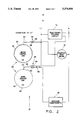
- FIG. 1 is a block diagram of the invention.
- FIG. 2 shows a camstack at 0°.
- FIG. 3 shows the camstack at 4.5°.
- FIG. 4 shows the camstack at 30°.
- FIG. 5 is a schematic of an electronic pulse circuit.
- FIG. 6 is a camstack drive motor advancement pulse diagram.
- FIG. 7 is a camstack rotation diagram.
- the cam-operated switching means 12 further comprises a camstack 20, a motor control cam 22, a rapid advance cam 24, a motor control switch 26, and a rapid advance switch 28.
- the camstack 20 is driven by the camstack drive motor 16 for rotation.
- the motor control cam 22 is carried on the camstack 20 and has a top profile 30 and a bottom profile 32.
- the motor control switch 26 is responsive to the motor control cam 22 and includes a motor control cam follower 34, a motor control cam follower contact 36 connected to L1 and a camstack drive motor contact 38 connected to the camstack drive motor 16.
- the rapid advance cam 24 is carried on the camstack 20 and has a machine components profile 40 and a rapid advance profile 42.
- the rapid advance switch 28 is responsive to the rapid advance cam 24 and includes a rapid advance cam follower 44, a rapid advance cam follower contact 46, a rapid advance contact 48, and a machine components contact 50.
- the rapid advance contact 48 is connected to the camstack drive motor 16; the machine components contact 50 is connected to machine components 18; and, the rapid advance cam follower contact 46 is connected to function switch 52.
- Function switch 52 is connect to L1 and is opened to disable the rapid advance switch 28 and closed to enable the rapid advance switch 28. Function switch 52 would typically be mounted in an appliance control console, so an appliance operator could open or close the switch to select an appliance function such as a cleaning cycle.
- the electronic pulsing circuit 14 comprises: a DC power supply; an integrated circuit configuration circuit; and, a motor switching circuit.
- Line terminals L1 and N are connected to AC line and AC neutral respectively.
- the DC power supply includes varistor 54, resistor 56, diode 58, capacitor 60, resistor 62, and Zener diode 64.
- Varistor 54 is connected across L1 and N to suppress transient voltages to prevent damage to circuit components.
- Resistor 56 is connected in series with diode 58 and limits current to diode 58 and capacitor 60.
- Diode 58 is a half-wave rectifier and capacitor 60 serves as a filter.
- Resistor 62 is also a current limiting resistor that cooperates with Zener diode 64 to establish V cc at approximately 5 VDC.
- the integrated circuit (IC) configuration circuit includes the resistor-capacitor (RC) network of resistor 66, resistor 68, and capacitor 70. Values of the RC network can be modified to vary the duty cycle of the pulse the electronic pulsing circuit 14 will generate. Capacitor 74 serves to suppress noise at V cc .
- the IC 72 is an Advanced Linear Devices (ALD) 1502 high speed micropower timer configured in the astable mode as a free running oscillator.
- ALD Advanced Linear Devices
- the motor switching circuit includes resistor 76, resistor 78, transistor 80, and triac 82 having triac gate 84. Resistors 76 and 78 are current limiting resistors. Transistor 80 is a switching transistor. When IC 72 pin 3 is high, transistor 80 is “on” thus keeping triac gate 84 low enough to maintain triac 82 “off” preventing current flow to the camstack drive motor 16. When IC 72 pin 3 goes low, transistor 80 turns “off” causing triac gate 84 to go high enough to turn triac 82 "on” allowing current flow to the camstack drive motor 16. Referring to FIG. 6 the electronic pulsing circuit 14 (FIG. 5) as configured will generate a five (5) second camstack drive motor advancement pulse every sixty-four (64) seconds. There is no feedback from the cam-operated switching means 12 to the electronic pulsing circuit 14 (FIG. 1).
- the camstack drive motor 16 is a synchronous fractional horsepower motor.
- Machine components 18 refers to an appliance component other than a timer such as a pump, motor, heater, or fill valve.
- a camstack rotation diagram (not a camstack timing diagram), which displays functions of the camstack drive motor advancement pulse 86, the motor control switch 26, and the rapid camstack advance switch 28 in relation to degrees of camstack rotation. Functioning of the camstack drive motor advancement pulse 86 and motor control switch 26 are displayed next to each other to show their cooperation in providing power to the camstack drive motor 16. The rapid camstack advance switch 28 is shown activated with function switch 52 closed.
- the camstack drive motor advancement pulse 86 is not providing power to the camstack drive motor 16.
- the motor control switch 26 is providing power 88 to the camstack drive motor 16.
- the rapid advance switch 28 is providing power 90 to machine components 18.
- the electronic pulsing circuit 14 as configured provides a five (5) second camstack drive motor advancement pulse every sixty-four (64) seconds, a time delay will occur before the electronic pulsing circuit 12 provides power to the camstack drive motor 16 for rotation.
- the camstack drive motor advancement pulse 86 (FIG. 6) is provided to the camstack drive motor 16
- the camstack drive motor advancement pulse 86 (FIG. 6) will rotate the camstack at least the number of degrees required for the motor control cam follower 34 to rise to the top profile 30 and close the motor control switch 26.
- the rapid advance cam follower contact 46 and machine components contact 50 remain closed providing power to machine components 18.
- camstack drive motor advancement pulse 86 now provides power 92 to the camstack drive motor 16 for rotation of the camstack 20.
- the camstack drive motor advancement pulse 86 will provide power to rotate the camstack 20 farther than necessary for the motor control switch 26 to close and provide power to the camstack drive motor 16.
- the camstack drive motor advancement pulse 86 overdrives 94 the camstack drive motor 16 to compensate for mechanical tolerances.
- the motor control switch 26 no longer provides power to the camstack drive motor 16.
- the rapid advance switch 28 continues to provide power to machine components 18.
- the camstack drive motor advancement pulse 86 is no longer providing power to the camstack drive motor 16. Also the motor control switch 26 does not provide power to the camstack drive motor 16.
- the rapid advance switch 28 now provides power 96 to the camstack drive motor 16, and the rapid advance switch 28 no longer provides power to machine components 18.
- the rapid advance switch 28 stops providing power to machine components 18 prior to application of power to the camstack drive motor 16. This is caused by the degrees of rotation required for the rapid advance cam follower 44 to rise and close the rapid advance cam follower contact 46 with the rapid advance contact 48.
Landscapes
- Connection Of Motors, Electrical Generators, Mechanical Devices, And The Like (AREA)
Abstract
Description
Claims (14)
Priority Applications (1)
| Application Number | Priority Date | Filing Date | Title |
|---|---|---|---|
| US07/975,055 US5374856A (en) | 1992-11-12 | 1992-11-12 | Timer motor incremental drive |
Applications Claiming Priority (1)
| Application Number | Priority Date | Filing Date | Title |
|---|---|---|---|
| US07/975,055 US5374856A (en) | 1992-11-12 | 1992-11-12 | Timer motor incremental drive |
Publications (1)
| Publication Number | Publication Date |
|---|---|
| US5374856A true US5374856A (en) | 1994-12-20 |
Family
ID=25522662
Family Applications (1)
| Application Number | Title | Priority Date | Filing Date |
|---|---|---|---|
| US07/975,055 Expired - Lifetime US5374856A (en) | 1992-11-12 | 1992-11-12 | Timer motor incremental drive |
Country Status (1)
| Country | Link |
|---|---|
| US (1) | US5374856A (en) |
Citations (5)
| Publication number | Priority date | Publication date | Assignee | Title |
|---|---|---|---|---|
| US3609390A (en) * | 1968-05-27 | 1971-09-28 | Chamberlain Mfg Corp | Trigger circuit |
| US3760189A (en) * | 1972-10-10 | 1973-09-18 | Niagara Machine & Tool Works | Motion detecting apparatus |
| USRE29086E (en) * | 1963-03-20 | 1976-12-21 | P. R. Mallory & Co., Inc. | Adjustable interval time switch device |
| US4362953A (en) * | 1981-06-17 | 1982-12-07 | The Scott & Fetzer Company | Electronically regulated electromechanical appliance control |
| US4857758A (en) * | 1988-04-08 | 1989-08-15 | Worldtronics International | Cycle timer for household appliance |
-
1992
- 1992-11-12 US US07/975,055 patent/US5374856A/en not_active Expired - Lifetime
Patent Citations (5)
| Publication number | Priority date | Publication date | Assignee | Title |
|---|---|---|---|---|
| USRE29086E (en) * | 1963-03-20 | 1976-12-21 | P. R. Mallory & Co., Inc. | Adjustable interval time switch device |
| US3609390A (en) * | 1968-05-27 | 1971-09-28 | Chamberlain Mfg Corp | Trigger circuit |
| US3760189A (en) * | 1972-10-10 | 1973-09-18 | Niagara Machine & Tool Works | Motion detecting apparatus |
| US4362953A (en) * | 1981-06-17 | 1982-12-07 | The Scott & Fetzer Company | Electronically regulated electromechanical appliance control |
| US4857758A (en) * | 1988-04-08 | 1989-08-15 | Worldtronics International | Cycle timer for household appliance |
Similar Documents
| Publication | Publication Date | Title |
|---|---|---|
| US5166641A (en) | Phase-locked loop with automatic phase offset calibration | |
| US20090072809A1 (en) | Method for detection of the presence of a load and drive circuit | |
| US5374856A (en) | Timer motor incremental drive | |
| US4011516A (en) | Frequency correction arrangement | |
| US7592852B2 (en) | Methods for controlling driving circuits | |
| US6160372A (en) | Solid state motor start method and apparatus | |
| US6495996B1 (en) | Linear motor control with triac and phase locked loop | |
| US4456087A (en) | Vehicle power steering apparatus | |
| US3956644A (en) | Integral cycle, precise zero voltage switch | |
| JPS63503342A (en) | Method and apparatus for controlling an electromagnet excited by an AC current to engage two parts | |
| US4145647A (en) | Arrangement for controlling the speed and rotary direction of a three-phase asynchronous motor | |
| US3295037A (en) | Electronic bi-directional d. c. motor braking | |
| US3515311A (en) | Control arrangement for a regenerator unit in a continuous developer | |
| US4425513A (en) | Method and device for providing dwell in timer controlled appliances | |
| SU1458961A1 (en) | Controlled thyratron motor | |
| US6025682A (en) | Infinitely variable wash action | |
| CN111384937B (en) | Load control circuit, load control method, and storage medium | |
| US3201671A (en) | Rotor controlled step motor | |
| US3365639A (en) | Light responsive motor start control circuit | |
| US3746441A (en) | Motion picture projector | |
| WO2008038125A2 (en) | Electronic starter device for an electric motor, in particular for a compressor of a refrigerating circuit of an electric household appliance | |
| AU2022202687A1 (en) | An arrangement and method for generation and propagation of a control on signal for a load switch arrangement for a two-wire trailing edge dimmer arrangement | |
| SU390505A1 (en) | DEVICE FOR CONTROLLING STEP ENGINE | |
| GB1427950A (en) | Dc motor circuits | |
| KR940008831B1 (en) | Proportional valve driving device |
Legal Events
| Date | Code | Title | Description |
|---|---|---|---|
| AS | Assignment |
Owner name: EMERSON ELECTRIC CO., MISSOURI Free format text: ASSIGNMENT OF ASSIGNORS INTEREST.;ASSIGNORS:ZINK, DAVID E.;NAYLOR, MICHAEL A.;JORDAN, LESLIE S.;REEL/FRAME:006399/0556 Effective date: 19930121 |
|
| FEPP | Fee payment procedure |
Free format text: PAYOR NUMBER ASSIGNED (ORIGINAL EVENT CODE: ASPN); ENTITY STATUS OF PATENT OWNER: LARGE ENTITY |
|
| AS | Assignment |
Owner name: EMERSON ELECTRIC CO., MISSOURI Free format text: ASSIGNMENT OF ASSIGNORS INTEREST;ASSIGNORS:ZINK, DAVID EUGENE;NAYLOR, MICHAEL ALLEN;JORDAN, LESLIE SPENCE;REEL/FRAME:007062/0746 Effective date: 19940712 |
|
| STCF | Information on status: patent grant |
Free format text: PATENTED CASE |
|
| FPAY | Fee payment |
Year of fee payment: 4 |
|
| FPAY | Fee payment |
Year of fee payment: 8 |
|
| FPAY | Fee payment |
Year of fee payment: 12 |