US5403245A - Control device for vehicular engine having an automatic transmission and its control method - Google Patents
Control device for vehicular engine having an automatic transmission and its control method Download PDFInfo
- Publication number
- US5403245A US5403245A US08/052,677 US5267793A US5403245A US 5403245 A US5403245 A US 5403245A US 5267793 A US5267793 A US 5267793A US 5403245 A US5403245 A US 5403245A
- Authority
- US
- United States
- Prior art keywords
- engine
- torque
- automatic transmission
- speed
- rotation speed
- Prior art date
- Legal status (The legal status is an assumption and is not a legal conclusion. Google has not performed a legal analysis and makes no representation as to the accuracy of the status listed.)
- Expired - Lifetime
Links
Images


Classifications
-
- B—PERFORMING OPERATIONS; TRANSPORTING
- B60—VEHICLES IN GENERAL
- B60W—CONJOINT CONTROL OF VEHICLE SUB-UNITS OF DIFFERENT TYPE OR DIFFERENT FUNCTION; CONTROL SYSTEMS SPECIALLY ADAPTED FOR HYBRID VEHICLES; ROAD VEHICLE DRIVE CONTROL SYSTEMS FOR PURPOSES NOT RELATED TO THE CONTROL OF A PARTICULAR SUB-UNIT
- B60W10/00—Conjoint control of vehicle sub-units of different type or different function
- B60W10/04—Conjoint control of vehicle sub-units of different type or different function including control of propulsion units
- B60W10/06—Conjoint control of vehicle sub-units of different type or different function including control of propulsion units including control of combustion engines
-
- B—PERFORMING OPERATIONS; TRANSPORTING
- B60—VEHICLES IN GENERAL
- B60W—CONJOINT CONTROL OF VEHICLE SUB-UNITS OF DIFFERENT TYPE OR DIFFERENT FUNCTION; CONTROL SYSTEMS SPECIALLY ADAPTED FOR HYBRID VEHICLES; ROAD VEHICLE DRIVE CONTROL SYSTEMS FOR PURPOSES NOT RELATED TO THE CONTROL OF A PARTICULAR SUB-UNIT
- B60W10/00—Conjoint control of vehicle sub-units of different type or different function
- B60W10/04—Conjoint control of vehicle sub-units of different type or different function including control of propulsion units
-
- B—PERFORMING OPERATIONS; TRANSPORTING
- B60—VEHICLES IN GENERAL
- B60W—CONJOINT CONTROL OF VEHICLE SUB-UNITS OF DIFFERENT TYPE OR DIFFERENT FUNCTION; CONTROL SYSTEMS SPECIALLY ADAPTED FOR HYBRID VEHICLES; ROAD VEHICLE DRIVE CONTROL SYSTEMS FOR PURPOSES NOT RELATED TO THE CONTROL OF A PARTICULAR SUB-UNIT
- B60W10/00—Conjoint control of vehicle sub-units of different type or different function
- B60W10/10—Conjoint control of vehicle sub-units of different type or different function including control of change-speed gearings
- B60W10/11—Stepped gearings
- B60W10/115—Stepped gearings with planetary gears
-
- B—PERFORMING OPERATIONS; TRANSPORTING
- B60—VEHICLES IN GENERAL
- B60W—CONJOINT CONTROL OF VEHICLE SUB-UNITS OF DIFFERENT TYPE OR DIFFERENT FUNCTION; CONTROL SYSTEMS SPECIALLY ADAPTED FOR HYBRID VEHICLES; ROAD VEHICLE DRIVE CONTROL SYSTEMS FOR PURPOSES NOT RELATED TO THE CONTROL OF A PARTICULAR SUB-UNIT
- B60W30/00—Purposes of road vehicle drive control systems not related to the control of a particular sub-unit, e.g. of systems using conjoint control of vehicle sub-units, or advanced driver assistance systems for ensuring comfort, stability and safety or drive control systems for propelling or retarding the vehicle
- B60W30/18—Propelling the vehicle
- B60W30/1819—Propulsion control with control means using analogue circuits, relays or mechanical links
-
- F—MECHANICAL ENGINEERING; LIGHTING; HEATING; WEAPONS; BLASTING
- F16—ENGINEERING ELEMENTS AND UNITS; GENERAL MEASURES FOR PRODUCING AND MAINTAINING EFFECTIVE FUNCTIONING OF MACHINES OR INSTALLATIONS; THERMAL INSULATION IN GENERAL
- F16H—GEARING
- F16H61/00—Control functions within control units of change-speed- or reversing-gearings for conveying rotary motion ; Control of exclusively fluid gearing, friction gearing, gearings with endless flexible members or other particular types of gearing
- F16H61/0021—Generation or control of line pressure
-
- B—PERFORMING OPERATIONS; TRANSPORTING
- B60—VEHICLES IN GENERAL
- B60W—CONJOINT CONTROL OF VEHICLE SUB-UNITS OF DIFFERENT TYPE OR DIFFERENT FUNCTION; CONTROL SYSTEMS SPECIALLY ADAPTED FOR HYBRID VEHICLES; ROAD VEHICLE DRIVE CONTROL SYSTEMS FOR PURPOSES NOT RELATED TO THE CONTROL OF A PARTICULAR SUB-UNIT
- B60W2510/00—Input parameters relating to a particular sub-units
- B60W2510/06—Combustion engines, Gas turbines
- B60W2510/0614—Position of fuel or air injector
- B60W2510/0628—Inlet air flow rate
-
- B—PERFORMING OPERATIONS; TRANSPORTING
- B60—VEHICLES IN GENERAL
- B60W—CONJOINT CONTROL OF VEHICLE SUB-UNITS OF DIFFERENT TYPE OR DIFFERENT FUNCTION; CONTROL SYSTEMS SPECIALLY ADAPTED FOR HYBRID VEHICLES; ROAD VEHICLE DRIVE CONTROL SYSTEMS FOR PURPOSES NOT RELATED TO THE CONTROL OF A PARTICULAR SUB-UNIT
- B60W2710/00—Output or target parameters relating to a particular sub-units
- B60W2710/06—Combustion engines, Gas turbines
- B60W2710/0666—Engine torque
-
- F—MECHANICAL ENGINEERING; LIGHTING; HEATING; WEAPONS; BLASTING
- F16—ENGINEERING ELEMENTS AND UNITS; GENERAL MEASURES FOR PRODUCING AND MAINTAINING EFFECTIVE FUNCTIONING OF MACHINES OR INSTALLATIONS; THERMAL INSULATION IN GENERAL
- F16H—GEARING
- F16H59/00—Control inputs to control units of change-speed-, or reversing-gearings for conveying rotary motion
- F16H59/36—Inputs being a function of speed
- F16H59/38—Inputs being a function of speed of gearing elements
- F16H2059/385—Turbine speed
-
- F—MECHANICAL ENGINEERING; LIGHTING; HEATING; WEAPONS; BLASTING
- F16—ENGINEERING ELEMENTS AND UNITS; GENERAL MEASURES FOR PRODUCING AND MAINTAINING EFFECTIVE FUNCTIONING OF MACHINES OR INSTALLATIONS; THERMAL INSULATION IN GENERAL
- F16H—GEARING
- F16H59/00—Control inputs to control units of change-speed-, or reversing-gearings for conveying rotary motion
- F16H59/36—Inputs being a function of speed
- F16H59/46—Inputs being a function of speed dependent on a comparison between speeds
- F16H2059/465—Detecting slip, e.g. clutch slip ratio
- F16H2059/467—Detecting slip, e.g. clutch slip ratio of torque converter
-
- F—MECHANICAL ENGINEERING; LIGHTING; HEATING; WEAPONS; BLASTING
- F16—ENGINEERING ELEMENTS AND UNITS; GENERAL MEASURES FOR PRODUCING AND MAINTAINING EFFECTIVE FUNCTIONING OF MACHINES OR INSTALLATIONS; THERMAL INSULATION IN GENERAL
- F16H—GEARING
- F16H59/00—Control inputs to control units of change-speed-, or reversing-gearings for conveying rotary motion
- F16H59/36—Inputs being a function of speed
-
- F—MECHANICAL ENGINEERING; LIGHTING; HEATING; WEAPONS; BLASTING
- F16—ENGINEERING ELEMENTS AND UNITS; GENERAL MEASURES FOR PRODUCING AND MAINTAINING EFFECTIVE FUNCTIONING OF MACHINES OR INSTALLATIONS; THERMAL INSULATION IN GENERAL
- F16H—GEARING
- F16H59/00—Control inputs to control units of change-speed-, or reversing-gearings for conveying rotary motion
- F16H59/74—Inputs being a function of engine parameters
-
- F—MECHANICAL ENGINEERING; LIGHTING; HEATING; WEAPONS; BLASTING
- F16—ENGINEERING ELEMENTS AND UNITS; GENERAL MEASURES FOR PRODUCING AND MAINTAINING EFFECTIVE FUNCTIONING OF MACHINES OR INSTALLATIONS; THERMAL INSULATION IN GENERAL
- F16H—GEARING
- F16H61/00—Control functions within control units of change-speed- or reversing-gearings for conveying rotary motion ; Control of exclusively fluid gearing, friction gearing, gearings with endless flexible members or other particular types of gearing
- F16H61/04—Smoothing ratio shift
- F16H61/0437—Smoothing ratio shift by using electrical signals
-
- F—MECHANICAL ENGINEERING; LIGHTING; HEATING; WEAPONS; BLASTING
- F16—ENGINEERING ELEMENTS AND UNITS; GENERAL MEASURES FOR PRODUCING AND MAINTAINING EFFECTIVE FUNCTIONING OF MACHINES OR INSTALLATIONS; THERMAL INSULATION IN GENERAL
- F16H—GEARING
- F16H63/00—Control outputs from the control unit to change-speed- or reversing-gearings for conveying rotary motion or to other devices than the final output mechanism
- F16H63/40—Control outputs from the control unit to change-speed- or reversing-gearings for conveying rotary motion or to other devices than the final output mechanism comprising signals other than signals for actuating the final output mechanisms
- F16H63/50—Signals to an engine or motor
- F16H63/502—Signals to an engine or motor for smoothing gear shifts
Definitions
- This invention relates to a control device for a vehicular engine having an automatic transmission and its control method for controlling an output of an engine when a speed is changed by an automatic transmission in a vehicle having the automatic transmission.
- FIG. 19 shows the construction of a conventional control device for a vehicular engine having an automatic transmission, which is disclosed, for instance, in Japanese Examined Patent Publication No. 20164/1991, wherein a reciprocating piston 23 is inserted into an engine main body 1 and a combustion chamber 24 is formed above the piston 23.
- An intake pipe 10 and an exhaust pipe 13 are respectively connected to the combustion chamber 24.
- a throttle valve 12 is provided upstream of the intake pipe 10.
- An injector 11 is provided downstream of the intake pipe 10 such that the injector 11 protrudes into the intake pipe 10.
- an intake air quantity sensor or a boost pressure sensor for detecting an inner passage pressure of the intake pipe 10 may be provided upstream of the throttle valve 12.
- An ignition plug 15 is disposed in the combustion chamber 24 such that the ignition plug 15 protrudes in the combustion chamber 24.
- a crank angle sensor 18 for detecting an engine crank angle and an intake stroke TDC is provided at the crank shaft 31 connected to the piston 23 and rotating cooperatingly therewith.
- the throttle valve 12 is connected with a throttle opening degree sensor 19, a servomotor 19b for driving the throttle valve 12 and a servomotor driving circuit 19a for driving the servomotor 19b.
- a stroke sensor 102 is provided to a car body for detecting a sinking quantity of a suspension, not shown, for the purpose of detecting a car weight.
- an automatic transmission 4 is provided with a gear position sensor 64 for detecting speed changing steps of a gear changing unit 43, a rotation speed sensor 62 for detecting a rotation speed of an output shaft of a torque converter 3, a vehicle speed sensor 63 for detecting a vehicle speed from a rotation number of a driving shaft, not shown, and a hydraulic control unit 5a for switching operational combination of a plurality of hydraulic friction elements 42 provided in the automatic transmission 4 for conforming the gear changing unit 43 to speed changing steps in accordance with the running state of a car.
- An electronic control unit (ECU) 6 receives detecting signals from sensors for detecting various running conditions of the engine, for instance, detecting signals from an intake quantity sensor, the throttle opening degree sensor 19, the crank angle sensor 18 and the like, or a speed changing signal of the automatic transmission 4 or the like, controls starting of fuel injection and a valve opening time of the injector 11 in accordance with a previously memorized program, and controls current flowing timing and a current flowing time of discharge energy to the ignition plug 15 through the ignition coil 16.
- the ECU 6 controls the intake quantity by controlling the throttle opening degree through the servomotor 19b such that the output torque of the engine can be provided in accordance with an operating quantity of the accelerator pedal.
- the ECU 6 performs the speed changing control by outputting a control signal for switching the operational combination of the hydraulic friction elements to a new combination in accordance with the speed changing step, to the hydraulic control unit 5a such that the speed changing step of the gear changing unit 43 of the automatic transmission 4 is optimized in accordance with a vehicle velocity provided by a vehicle velocity sensor 63 and the above running conditions of the engine.
- the ECU 6 is composed of a CPU, a ROM, a RAM, an A/D converter having a multiplexer, an I/O interface circuit, a common bus connecting these and the like.
- the CPU calculates a fuel injection quantity based on the data detected by the various sensors in accordance with a program memorized in the ROM, and outputs a pulse signal based on the calculated fuel injection quantity to the injector 11 through a driving circuit in the I/O interface circuit.
- the fuel injection quantity TAU 0 is determined based on the following equation (1).
- the ignition time SA 0 is calculated by a table look-up of an advance angle map which is previously determined by the rotation speed N e of the engine and the A/N value. The ignition timing and the current flowing time are controlled through the ignition signal driving circuit in the I/O interface circuit based on the calculated value.
- the ECU 6 predicts by calculation a target engine torque T er by the following equation (2), in accordance with the signals from the various sensor for detecting the various running conditions of the engine.
- K 1 and K 2 designate parameters for determining a characteristic of the output torque of the engine, wherein K 1 is a proportional coefficient of the output torque of the engine with regards to the accelerator opening degree "a" and K 2 , a proportional coefficient of the output torque with regards to the rotation speed N e of the engine, which are respectively calculated by the following equation (3).
- m designates a gear ratio (speed reducing ratio) of the gear changing device 43, C 1 and C 2 , constants which are previously obtained by experiments or the like and which provide the best driving feeling of the vehicle and W, vehicle weight provided by the following equation.
- W 0 designates a previously-known weight of only the car body, x, an output of the stroke sensor 102 which is a sinking quantity of the suspension caused by the weight of passengers or a mounted load and K s , a spring constant of suspension.
- the target throttle opening degree which provides the intake quantity necessary for outputting the target engine torque T er is read from a throttle opening degree table by the rotational speed N e of the engine and the target engine torque T er , which is outputted to the servomotor driving circuit 19a.
- the servomotor driving circuit 19a drives the servomotor 19a positively and negatively in accordance with a deviation between the actual throttle opening degree detected by the throttle opening degree sensor 19 and the target throttle opening degree, and controls the intake quantity such that the opening degree of the throttle valve 12 follows the target value, thereby controlling the engine to the target torque T er .
- the ECU 6 reads a target speed changing step from a predetermined shift pattern schedule table by the vehicle speed V sp detected by the vehicle speed sensor 63 and the torque T t of the output shaft of the torque converter, and performs the speed changing control wherein the operational combination of the hydraulic friction engaging elements is switched by outputting a control signal of an ON-OFF logic in accordance with the target speed changing step, to a shift solenoid valve in the hydraulic control unit 5a of the automatic transmission 4 such that the gear speed changing unit 43 is shifted from a current speed changing step to the target speed changing step.
- hydraulic wet clutches or brakes employed in the automatic transmission which conventionally achieves plural steps of gear changing ratios by a selective combination of a plurality of gears, performs engaging and disengaging of the transmission torque by supply and discharge of a hydraulic pressure called line pressure.
- this line pressure is controlled by regulating a spool opening degree by a set pressure and a feedback pressure in the axial direction of a pressure regulating valve employing a spool valve, and is set in accordance with the speed changing step and the output of the engine, for instance, increase of the throttle opening degree.
- the pulse width of fuel injection is regarded as approximately proportional to the output torque of the engine, and based on a predicted value of the engine torque, the line pressure of the automatic transmission is regulated.
- the output torque of the engine is not detected and the torque T t of the output shaft of the automatic transmission 4 which is the target in the speed changing operation, is indirectly predicted by calculation from the accelerator opening degree "a" and the rotation speed N E of the engine.
- the hydraulic pressure control is not performed in accordance with the torque T t of the output shaft of the automatic transmission 4. Accordingly, a speed changing shock may be caused by variations, timewise changes or the like of the engine or the hydraulic characteristics of the automatic transmission 4, which brings about a disagreeable feeling to a driver and a favorable shift quality is not provided.
- the engine output is predicted without directly detecting the engine torque
- the input torque of the automatic transmission is calculated based on an average characteristic of the torque converter
- a torque quantity considering a safety factor against a rapid load variation is regarded as the input torque for the automatic transmission
- the line pressure necessary for the torque transmission is calculated by a predetermined method, for instance, a map-look-up, thereby determining the line pressure.
- the actually necessitated line pressure is previously determined to a higher value so that disadvantage by, for instance, an excessive slip of the hydraulic wet clutches and brakes, is not caused by individual difference, aging and the like of the engine. Therefore, a driving loss of a pump of the automatic transmission increases, which causes to deteriorate a fuel cost of the engine.
- the accuracy of predicting the torque is deteriorated when the combustion efficiency of the engine changes by the change of the intake quantity or by a warming-up state of the engine, and as a result, the accuracy of controlling the line pressure is deteriorated.
- a control device for a vehicular engine having an automatic transmission comprising:
- an inner cylinder pressure sensor for detecting a pressure in a combustion chamber of an engine
- control means for controlling at least one of the output torque of the engine and a hydraulic pressure of the automatic transmission such that the torque of the output shaft of the automatic transmission conforms to a target torque.
- a control device for a vehicular engine having an automatic transmission comprising:
- an inner cylinder pressure sensor for detecting a pressure in a combustion chamber of an engine
- torque predicting means for calculating an output torque of the engine based on a detected value provided by detecting an output of the inner cylinder pressure sensor at a predetermined angle, for calculating a speed ratio of a rotation speed of an output shaft of a torque converter as compared to the rotation speed of the engine and for predicting a torque of an input shaft of the automatic transmission by calculating the torque of the input shaft of the automatic transmission based on the output torque of the engine, the rotation speed of the engine, the rotation speed of the output shaft of the torque converter and the speed ratio;
- hydraulic pressure controlling means for controlling the line pressure of the working fluid for supplying to the automatic transmission based on the torque of the input shaft of the automatic transmission predicted by the torque predicting means.
- a control method for a vehicular engine having an automatic transmission comprising the steps of:
- controlling the line pressure of the working fluid for supplying to the automatic transmission by calculating a target line pressure based on the predicted torque of the input shaft of the automatic transmission.
- the output torque of the engine is calculated
- the torque of the output shaft of the automatic transmission is calculated from the output torque of the engine, the rotation speed of the engine and the rotation speed of the output shaft of the torque converter, and at least one of the ignition timing, the fuel injection quantity, the throttle opening degree and the hydraulic pressure of the automatic transmission, is controlled such that the torque of the output shaft conforms to the target torque.
- the pressure in the combustion chamber of the engine is detected by the inner cylinder pressure sensor, the output of the inner cylinder pressure sensor is detected at the predetermined crank angle, and the control means calculates the torque of the engine and calculates the speed ratio of the torque converter from the ratio of the rotation speed of the output shaft of the torque converter as compared to the rotation speed of the engine.
- control means predicts the torque of the input shaft of the automatic transmission from the speed changing ratio of the automatic transmission, the output torque of the engine, the rotation speed of the engine, the rotation speed of the output shaft of the torque converter and the speed ratio of the torque converter. Based on the predicted value, the line pressure of the working fluid supplied to the automatic transmission is controlled by the hydraulic pressure controlling means.
- the pressure in the combustion engine of the engine is detected at the predetermined crank angle, the output torque of the engine is calculated based on the detected value, the speed ratio of the rotation speed of the engine as compared to the rotation speed of the output shaft of the torque converter, is calculated, and the torque of the input shaft of the automatic transmission is predicted by calculating the torque of the input shaft of the automatic transmission from the output torque of the engine, the rotation speed of the engine, the rotation speed of the output shaft of the torque converter and the speed ratio. Based on the predicted value, the line pressure of the working fluid supplied to the automatic transmission is controlled.
- FIG. 1 is a block diagram showing the construction of an embodiment 1 of this invention of a control device for a vehicular engine having an automatic transmission;
- FIG. 2 is a block diagram showing the construction of an electronic control unit (ECU) in FIG. 1;
- ECU electronice control unit
- FIG. 3 is a diagram showing a mounting state of an inner cylinder pressure sensor 17 in a combustion chamber of FIG. 1;
- FIG. 4 is a construction diagram of a gear changing unit of an automatic transmission 4 in FIG. 1;
- FIG. 5 is a construction diagram of a hydraulic pressure controlling unit of the automatic transmission 4 in FIG. 1;
- FIG. 6 is a main flowchart for explaining the operation of the embodiment 1 of this invention.
- FIG. 7 is a flowchart for explaining the operation of a crank angle interruption routine of the embodiment 1 of this invention.
- FIG. 8 is a main flowchart for explaining the operation of an embodiment 2 of this invention.
- FIG. 9 is a main flowchart for explaining the operation of an embodiment 3 of this invention.
- FIG. 10 is a main flowchart for explaining the operation of am embodiment 4 of this invention.
- FIG. 11 is a block diagram showing the construction of an embodiment 5 of this invention of a control device for a vehicular engine having an automatic transmission;
- FIG. 12 is a block diagram showing the construction of an electronic control unit (ECU) in FIG. 11;
- ECU electronice control unit
- FIG. 13 is a construction diagram of a gear changing unit of the automatic transmission 4 in FIG. 11;
- FIG. 14 is a construction diagram of a hydraulic pressure controlling unit of the automatic transmission 4 in FIG. 11;
- FIG. 15 is a main flowchart for explaining the operation of embodiment 5 of this invention.
- FIG. 16 is a flowchart for explaining the operation of embodiment 5 of this invention of a crank angle interruption routine
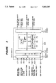
- FIG. 17 is a diagram showing the construction of a line pressure regulator 60 in FIG. 14;
- FIG. 18 is a characteristic diagram of a line pressure with respect to a control duty ratio of the line pressure regulator 60 in FIG. 14;
- FIG. 19 is a block diagram showing the construction of a conventional control device for a vehicular engine having an automatic transmission.
- FIG. 1 is a block diagram showing the construction of the embodiment of this invention of a control device for a vehicular engine having an automatic transmission.
- the torque converter 3 is provided with a pump 32, a turbine liner 33, a stator 34 and a one-way clutch 35, wherein the stator 34 is connected to a casing of the automatic transmission 4 through the one-way clutch 35, and rotates in a direction the same with that of the input shaft (the crank shaft of the engine) 31 by the function of the one-way clutch 35.
- the rotation thereof to the reverse direction is not allowable.
- a lock-up clutch 37 is provided between the input shaft 31 and the turbine liner 33 connected to an output shaft 36, which operates in a steady-state running mainly at high speed steps, and locks up the input shaft 31 and the output shaft 36 thereby promoting the transmission efficiency. Accordingly, the output of the engine main body 1 is transmitted to the turbine liner 33 by the lock-up clutch 37 or by rotating the inner working fluid by the pump 32, while increasing the torque under a counter-force by the stator 34. The torque transmitted to the turbine liner 33 is transmitted to the gear changing unit 43 through the output shaft (the input shaft of the automatic transmission 4) 36 of the torque converter 3.
- a reference numeral 14 designates an air-fuel ratio sensor, 17, an inner cylinder pressure sensor, 41, an output shaft, 42, the hydraulic friction engaging elements and 5b, the hydraulic pressure control unit.
- FIG. 4 is a conceptual diagram of the gear changing unit 43 capable of achieving the speed changing steps of forward 4 steps and reverse 1 step.
- the output shaft 36 is connected to an underdrive clutch (hereinafter UD clutch) C1, overdrive clutch (OD clutch) C2 and a reverse clutch (R clutch) C3 as the hydraulic friction engaging elements 42.
- the output side of the OD clutch C2 is connected to a first carrier 45 of a first simple planetary gear unit (hereinafter, first gear unit) PG1 through an intermediate shaft 45a, to a second carrier 48 of a second simple planetary gear unit (hereinafter, a second gear unit) PG2, and to a low reverse brake B1 as a hydraulic friction engaging element for stopping the rotation of the first intermediate shaft 45a.
- the output side of the UD clutch C1 is connected to a first sun gear 44 of the first gear unit PG1.
- the output side of an R clutch C3 is connected to a first ring gear 46 of the first gear unit PG1 through a second intermediate shaft 46a, to a second sun gear 47 of the second gear unit PG2 and to 2-4 brake B2 as a hydraulic friction engaging element for stopping the rotation of the second intermediate shaft 46a.
- the first gear unit PG1 is composed of the first sun gear 44, a first pinion gear 45b meshed with the first sun gear 44, the rotatable first carrier 45 which rotatably supports the first pinion gear 45b and the first ring gear 46 meshed with the first pinion gear 45b.
- the second gear unit PG2 is composed of the second sun gear 47, a second pinion gear 48a meshed with the second sun gear 47, the rotatable second carrier 48 which rotatably supports the second pinion gear 48a and the second ring gear 49 meshed with the second pinion gear 48a.
- the second ring gear 49 is connected to the output shaft 41 of the gear speed changing unit 43.
- the respective clutches C1 through C3 and the brakes B1 and B2 are provided with engaging piston devices or servo devices or the like, which perform engaging or disengaging operation by supplying and discharging hydraulic pressure.
- This hydraulic pressure is selectively supplied from the hydraulic pressure controlling unit 5b, and the speed changing steps of forward 4 steps and reverse 1 step are achieved by the operational combination of the clutches C1 through C3 and the brakes B1 and B2.
- Table 1 shows the operational state of the respective clutches C1 through C3 and the brakes B1 and B2 in the respective speed changing steps, wherein " ⁇ " mark designates the engaging of the clutch or the brake, whereas "-" mark designates the disengaging thereof.
- the first and second carriers 45 and 48 are fixed and become counter-force elements, and the driving force is transmitted to the output shaft 41 by engaging the R clutch C3, through the second intermediate shaft 46a, the first ring gear 46, the second sun gear 47, the second pinion gear 48a and the second ring gear 49, thereby achieving the reverse speed changing step.
- FIG. 5 shows the construction of the hydraulic pressure controlling unit 5b, wherein the hydraulic pressure generated by an oil pump 50 disposed on the crank shaft 31 of the engine and which is driven by the engine 1, is controlled to a constant pressure as a line pressure by a pressure regulating valve 51.
- a reference numeral 20 designates an oil pan.
- the controlled line pressure is supplied to a shifting control valve 52 which is operated by directly connecting to a shift lever, not shown, oil passages are selectively switched in accordance with the position of the shift lever, the supply of the hydraulic pressure to the clutches C1 to C3 and the brakes B1 and B2 which engage in the forward and the reverse steps, is performed through respective solenoid valves 55 through 58 or directly.
- the controlled line pressure is supplied to a torque converter control valve 54 through a pressure regulating valve 53 for the torque converter 3, which controls the torque converter control valve 54 indirectly by a lock-up solenoid valve 59 and engages or disengages the lock-up clutch 37 by controlling the hydraulic pressure of the lock-up clutch 37.
- the construction and the operation of the solenoid valves 55 through 59 for controlling the hydraulic pressure is publicly-known in "An analysis on the characteristic of a duty-control solenoid valve for converting electricity to hydraulic pressure", Transaction of the Automobile Engineering Society 1988, Vol. 42, No. 4, P. 517 through 523, wherein the hydraulic pressure control is performed by respectively duty-controlling the solenoid valves 55 through 59 in engaging and disengaging the respective clutches and brakes. That is to say, the hydraulic pressure in switching the respective clutches and brakes accompanied by transition from a speed changing step to another speed changing step is controlled by employing the solenoid valves 55 through 59.
- the 2-4 brake B2 is engaged by increasing the hydraulic pressure thereof by the solenoid valve 56 and at the same time, the low reverse brake B1 is disengaged by lowering the hydraulic pressure thereof by the solenoid valve 55 in accordance the increase of the hydraulic pressure of the 2-4 brake B1.
- FIG. 2 shows an outline construction of the ECU 6A.
- the output signals of the inner cylinder pressure sensor 17 and the like are inputted into an input interface 73 through an A/D converter 71 and a waveform shaper 72.
- An input signal from a gear position sensor 64 is inputted to the input interface 73.
- the output of the input interface 73 is inputted to a microprocessor 74.
- the fuel quantity TAU, an ignition timing SA, a throttle opening degree Th and a hydraulic pressure setting value DU which are to be supplied to the engine main body 1 and the automatic transmission 4, are calculated.
- the ECU 6A outputs control signals to the injector 11, the ignition coil 16, the servomotor driving circuit 19b and the solenoid valves 55 through 59 in the hydraulic pressure controlling unit 5b, through an output interface 78.
- the control procedure and the data of the microprocessor 74 are previously memorized in the ROM 76.
- the RAM 75 temporarily stores data in the calculation procedure.
- a digital signal processor (DSP) 77 calculates an output signal of the inner cylinder pressure sensor 17 at high speed in synchronism with the crank angle, and transmits the calculation result to the microprocessor 74 through the common bus.
- DSP digital signal processor
- FIG. 3 shows the inner cylinder pressure sensor 17 for detecting the pressure in the combustion chamber 24 and its mounting situation.
- a reference numeral 21 designates a cylinder block, 22, a cylinder head, 23, a piston, and 17, the inner cylinder pressure sensor having a pressure detecting unit 17a, which is attached to the cylinder block 21.
- a numeral 25 designates a pressure leading unit for leading the pressure from the combustion chamber 24 to the inner cylinder pressure sensor 17.
- the inner cylinder pressure sensor 17 outputs an inner cylinder pressure signal which is proportional to the pressure in the combustion chamber 24.
- the pressure detecting unit 17a exposed to the pressure leading unit 25, measures the pressure by a pressure transducing element through, for instance, silicon oil enclosed in a metallic diaphragm or the like.
- a semiconductor-type sensor which stands an elevated temperature (300° C.) and a high pressure (60 kg/cm 2 ), is employed.
- the semiconductor-type sensor employs a strain gage formed by injecting impurity such as boron on single crystal silicon formed on a silicon oxide, and measures the pressure applied to the silicon oil by converting the pressure to a strain quantity.
- a piezoelectric element may be employed as the inner cylinder pressure sensor 17.
- FIG. 6 A main routine shown in FIG. 6 is processed by the microprocessor 74 in the ECU 6, whereas an interruption routine synchronizing with the crank angle of FIG. 7 is processed by the DSP 77 in the ECU 6, of which calculation result is transmitted to the microprocessor 74 at predetermined timings.
- an explanation will be given of the operation of the main routine based on the flowchart of FIG. 6. The explanation will be given to a case of a single cylinder for simplicity. However, in case of multi-cylinders, a treatment is added which recognizes the respective cylinders based on the output signal of the crank angle sensor 18 and a treatment similar to the case of a single cylinder is performed for each of the cylinders.
- Step S100 The operation starts in Step S100.
- Step S101 the operation reads the throttle opening degree T h from the output of the throttle opening degree sensor 19 and memorizes it in the RAM 75.
- Step S102 the operation calculates the rotation speed ⁇ e and its change ratio ⁇ e based on the crank angle signal from the crank angle sensor 18 and memorizes them in the RAM 75.
- Step S103 the operation calculates the rotation speed ⁇ t of the output shaft of the torque converter and its change ratio ⁇ t from the output of the rotation speed sensor 62 and memorizes them in the RAM 75.
- Step 105 the operation calculates a vehicle speed (rotation speed of the output shaft of the automatic transmission) ⁇ 0 and memorizes it in the RAM 75.
- Step S106 the operation reads an indicated mean effective pressure ⁇ P i which is a calculation result of the DSP 77 treated by a crank angle interruption routine to be mentioned later, from a RAM incorporated in the DSP 77, and memorizes it in the RAM 75.
- Step S107 the operation reads an output of the gear position sensor 64, detects a shift lever position (either one of forward, neutral and reverse modes of the automatic transmission 4 is selected by the operation of a driver) of the automatic transmission 4, reads a target speed changing step from a shift pattern schedule table which is previously provided with respect to the shift lever position, the throttle opening degree T h and the vehicle speed ⁇ 0 , and memorizes the target speed changing step and a gear ratio i r in the RAM 75.
- a shift lever position either one of forward, neutral and reverse modes of the automatic transmission 4 is selected by the operation of a driver
- Step S108 the operation reads the current speed changing step of the automatic transmission 4 (the speed changing step and the corresponding gear ratio i a when the preceding speed changing is finished, are memorized in the RAM 75) from the RAM 75, and determines whether the automatic transmission 4 is performing the upshifting by comparing the value with the target speed changing step detected in Step S107.
- the operation proceeds to Step S109.
- Step S109 the operation determines whether the operation state of the automatic transmission 4 performing the upshifting is in an inertia phase.
- the inertia phase designates a state wherein the rotation speed ⁇ e of the engine and the rotation speed ⁇ t of the output shaft of the torque converter are not converged to the target revolution numbers when the speed changing is finished, by inertias of the engine and the automatic transmission 4, although a mechanical gear changing (switching of clutches) of the automatic transmission 4 is finished.
- Step S109 when a relationship of ⁇ t ⁇ i a ⁇ 0 , is established between the speed of the input shaft and the output shaft of the automatic transmission 4 from the gear ratio i a of the current speed changing step, the vehicle speed ⁇ 0 and the rotation speed ⁇ t of the output shaft of the torque converter, the operation determines that the current speed changing state is in the inertia phase, and proceeds to Step S110. When the operation determines NO at either one of the Steps S108 and S109, the operation returns to START.
- Step S110 the operation proceeds to S112, wherein the operation resets an ignition timing correction value ⁇ SA as 0, renews the target speed changing step and the gear ratio i r as the current speed changing step and the gear ratio i a , memorizes them in the RAM 75, finishes the treatment of the main routine and returns to START.
- ⁇ SA ignition timing correction value
- Step S111 the operation determines whether the torque converter is in a lock-up operating state by a lock-up operating region map of the torque converter 3 which is previously determined by the throttle opening degree T h and the rotation speed ⁇ t of the output shaft of the torque converter.
- the operation proceeds to Step S113.
- Step S113 the operation reads coefficients ⁇ , ⁇ and ⁇ which are predetermined in accordance with the gear ratio i r and the speed ratio e from the ROM 76, and calculates and memorizes the torque ⁇ T 0 of the output shaft of the automatic transmission 4 based on the following equation (6) by employing the indicated mean effective pressure ⁇ P i , the change ratio ⁇ e of the rotation speed of the engine and the change ratio ⁇ t of the rotation speed of the output shaft of the torque converter which are memorized in the RAM 75.
- the set values of ⁇ and ⁇ may be changed in accordance with a range of the speed ratio e of the torque converter.
- Step S114 calculates and memorizes the torque ⁇ T 0 of the output shaft by employing the following equation (7).
- k is a coefficient corresponding to a mechanical connection state of shaft and gear from the engine to the automatic transmission 4 in the lock-up operating state, which is predetermined in accordance with the gear ratio i r .
- Step S115 After calculating and memorizing the torque ⁇ T 0 of the output shaft in Steps S113 and S114, the operation proceeds to S115, reads an accelerator pedal opening degree THA from an output of the accelerator pedal opening degree sensor 101 and memorizes it in the RAM 75.
- Step S116 the operation reads a target torque ⁇ T or which is predetermined with respect to the accelerator pedal opening degree THA and the vehicle speed ⁇ 0 .
- Step S118 the operation calculates and memorizes an ignition timing correction value ⁇ SA by the following equation (8).
- Step S119 the operation adds the ignition timing correction value ⁇ SA to a basic ignition timing SA 0 , and finishes the main routine by calculating and memorizing the ignition timing SA.
- the operation calculates the ignition timing correction value ⁇ SA based on the proportional and the integral gains in Step S118.
- the operation may perform a fuzzy calculation inputted with the rotation speed ⁇ e of the engine and the torque error ⁇ E r .
- the operation reads a crank angle ⁇ from the output of the crank angle sensor 18, in Step S201.
- the operation measures and memorizes the pressure signal of the inner cylinder pressure sensor 17 as the inner cylinder pressure value P( ⁇ ) at the crank angle ⁇ .
- the operation determines whether the crank angle ⁇ is the intake TDC ⁇ 0 .
- Step S206 the operation determines whether the crank angle ⁇ is in a range of 0 ⁇ 180 setting the intake TDC at 0° CA, that is, the crank angle ⁇ is in the intake stroke.
- the operation determines whether the crank angle ⁇ is in the compression stroke in Step S208.
- Step S210 the operation determines whether the crank angle ⁇ is in the explosion stroke.
- Step S214 the operation memorizes a difference ⁇ P i (j) between the indicated mean effective pressure P i (j-1) at the preceding time (j-1) and the current P i (j) as in the following equation (10).
- Example 2 shows a case wherein a correction is performed for the fuel injection quantity TAU.
- FIG. 8 is a flowchart showing the operation. Steps S100 through S111 and S113 through S117 are the same as those in Example 1.
- Step S120 the operation resets the fuel injection quantity correction value ⁇ TAU to zero, renews the target speed changing step and the gear ratio i r as the current speed changing step and the gear ratio i a , memorizes these values in the RAM 75 and returns to START.
- Step S121 the operation calculates and memorizes the fuel injection quantity correction value ⁇ TAU by the following equation (11).
- Step S122 the operation adds the fuel injection quantity correction value ⁇ TAU to the basic fuel injection quantity TAU 0 , and finishes the main routine by calculating and memorizing the fuel injection quantity TAU.
- the effect is the same as in Example 1.
- FIG. 9 is a flowchart showing the operation of Example 3, wherein Steps S100 through S111 and S113 through S117 are the same with those in Example 1.
- Step 123 the operation resets the throttle opening degree correction value ⁇ T h to zero, renews the target speed changing step and the gear ratio i r as the current speed changing step and the gear ratio i a , and returns to START after memorizing the values in the RAM 75.
- Step S124 the operation calculates and memorizes the throttle opening degree correction value ⁇ T h by the following equation (12).
- Step S125 the operation adds the correction value ⁇ T h to the basic throttle opening degree T h0 , and finishes the main routine by calculating and memorizing the throttle opening degree T h .
- the effect is the same as in Example 1.
- Step S127 the operation calculates and memorizes a duty correction value ⁇ DU by the following equation (13), based on the torque error ⁇ E r provided by Step S117, as the hydraulic pressure control signal of the engaging clutch, for instance, that of the solenoid valve 56 for controlling the hydraulic pressure of the 2-4 brake B2 in case of the power-on 1-2 upshifting.
- Step S1208 the operation adds the duty correction value ⁇ DU to a basic duty value DU O in speed changing which is read from an engaging initial duty value table for the respective clutches and brakes which is predetermined in accordance with the engine load, in accordance with the throttle opening degree T h and the rotation speed ⁇ 0 of the output shaft of the automatic transmission, and returns to START of the main routine after calculating and memorizing the duty output value DU. Furthermore, when the speed changing is finished, in Step S110, the operation resets the correction value ⁇ DU to zero in Step S126 and returns to START of the main routine.
- the duty value of DU is selected by the ECU 6 in accordance with the kind of speed changing.
- the 2-4 solenoid valve 56 is selected at the hydraulic pressure control unit 5b, a duty control signal of, for instance, a driving frequency of 50 Hz, is outputted from the ECU 6 as the hydraulic pressure control signal and the 2-4 brake B2 is controlled to engage.
- the torque T 0 of the output shaft of the automatic transmission in speed changing is controlled to conform to the target torque T or , based on the calculated results, by outputting at least one of the ignition timing SA, the fuel injection quantity TAU, the throttle opening degree T h and the hydraulic pressure controlling value DU as the operating quantity from the ECU 6.
- FIG. 11 is a block diagram showing a total construction of a control device for a vehicular engine having an automatic transmission which is provided with a hydraulic pressure controlling device for controlling a line pressure of a working fluid to be supplied to the automatic transmission based on a torque of an input shaft of the automatic transmission.
- the construction of invention in Example 5 is the same with that of the embodiment 1 shown in FIG. 1, except the calculation treatment or the data setting method of mainly a microprocessor in the control unit (hereinafter ECU) 6B, are different from those in embodiment 1.
- ECU microprocessor in the control unit
- the ECU 6B controls the servo driving circuit 19a, by which the servo motor 19b is driven to perform the opening degree control of the throttle valve 12.
- the opening degree of the throttle 12 is detected by the throttle opening degree sensor 19, and the throttle opening degree signal 65 is inputted to the ECU 6.
- the intake manifold 10 is attached with the injector 11, which injects fuel into the intake manifold 10 by the control of the ECU 6.
- the torque converter 3 shown in FIG. 11 is provided with the pump impeller 32, the turbine liner 33, the stator 34 and the one-way clutch 35.
- the stator 34 is connected to a transmission case, not shown, through the one-way clutch 35, and rotates in the direction the same with that of the input shaft 31 (crankshaft of engine) of the torque converter, by the function of the one-way clutch 35. However, the rotation thereof in the reverse direction is not allowable.
- lock-up clutch 37 is provided between the input shaft 31 and the turbine liner 33 which is connected to the output shaft 36.
- This lock-up clutch 37 mainly operates in a steady-state running at the high speed stage (gear) and functions as a clutch for promoting the transmission efficiency by locking up the input shaft 31 and the output shaft 36 of the torque converter 3 at the high gear stage.
- the output of the engine 1 is transmitted to the turbine liner 33 through the lock-up clutch 37, or by rotating the inside working fluid by the pump impeller 32 and by increasing the torque by the working fluid under the counter-force by the stator 34.
- the torque transmitted to the turbine liner 33 is transmitted to the speed changing gear mechanism 43 arranged after the torque converter 3, through the output shaft 36 (also an input shaft of the automatic transmission) of the torque converter 3.
- the rotation speed of the turbine liner 33 is detected by the turbine liner rotation sensor 62.
- the detected output is transmitted to the ECU 6B.
- the rotation speed of the output shaft 41 of the automatic transmission is detected by the automatic transmission output shaft rotation sensor 63, which also is transmitted to the ECU 6B.
- a reference numeral 42 designates the hydraulic friction engaging elements of the automatic transmission 4, and 64, the shift position sensor, which detects the shift position of the automatic transmission 4 and of which detected output is transmitted to the ECU 6B.
- the ECU 6B transmits the valve controlling signal 66 to the hydraulic pressure controlling device 5.
- FIG. 13 is a skelton diagram of the gear speed changing device 43 capable of achieving the speed changing steps of four forward steps (gear ratio) and one reverse step.
- the output shaft 36 of the torque converter 3 is connected to the underdrive clutch C1 (hereinafter UD clutch C1), the overdrive clutch C2 (hereinafter OD clutch C2) and the reverse clutch C3 (hereinafter R clutch C3) as hydraulic friction engaging elements.
- the output side of the OD clutch C2 is connected to the first carrier 45 of the first simple planetary gear device PG1 (hereinafter, the first gear device PG1) through the first intermediate shaft 45a, to the second carrier 48 of the second simple planetary gear device PG2 (hereinafter, second gear device PG2), and to the low reverse brake B1 (hereinafter, L&R brake B1) as a hydraulic friction engaging element for stopping the rotation of the intermediate shaft 45a.
- the output side of the UD clutch C1 is connected to the first sun gear 44 of the first gear device PG1.
- the output side of the R clutch C3 is connected to the first ring gear 46 of the first gear device PG1 through the second intermediate shaft 46a, to the second sun gear 47 of the second gear device PG2, and to the 2-4 brake B2 as the hydraulic friction engaging element for stopping the rotation of the second intermediate shaft 46a.
- the first gear device PG1 is composed of the first sun gear 44, the first pinion gear 45b in mesh with the first sun gear 44, the first carrier 45 which rotatably supports the first pinion gear 45b and is rotatable per se, and the first ring gear 46 in mesh with the first pinion gear 45b.
- the second gear device PG2 is composed of the second sun gear 47, the second pinion gear 48a in mesh with the second sun gear 47, the second carrier 48 which rotatably supports the second pinion gear 48a and is rotatable per se, and the second ring gear 49 in mesh with the second pinion gear 48a.
- the second ring gear 49 is connected to the output shaft 41 of the gear speed changing device 43.
- the respective clutches and brakes are provided with piston devices or servo devices for engaging, not shown.
- the engaging and disengaging operations are performed by supplying and discharging the working fluid pressure.
- the working fluid pressure is selectively supplied to the respective clutches and brakes.
- Table 2 shows the operational state of the respective clutches and brakes.
- " ⁇ " mark designates the engaging of clutch or brake
- "-" mark the disengaging thereof.
- n is a sheet number of clutch, A, a pressure receiving area, r, an average radius, ⁇ , coefficient of friction, P, supplied working fluid pressure, and P 0 an equivalent offset pressure operated by a return spring, which are determined by the dimension, the shape and the like inherent to the respective clutch and brake.
- the working fluid pressure corresponding to the torque can be calculated based on equation (14).
- the first carrier 45 and second carrier 48 are fixed and become counter-force elements.
- the driving force from the torque converter 3 is transmitted to the input shaft 36, the UD clutch C1, the first sun gear 44, the first pinion gear 45b, the first ring gear 46, the second sun gear 47, the second pinion gear 48a, the second ring gear 49 and finally to the output shaft 41, which achieves the first speed (gear).
- the allotted torque of the UD clutch C1 is equal to the torque T t of the input shaft of the automatic transmission.
- the allotted torque of the LR brake is (i 1 -1) ⁇ T t .
- the similar relationship can be read from Table 2.
- the total first gear device PG1 integrally rotates since the first sun gear 44 and the first carrier 45 rotate integrally. Accordingly, the total second gear device PG2 similarly rotates integrally, which achieves the third speed (gear) wherein the input shaft 36 and the output shaft 41 share the same rotation speed.
- FIG. 14 is a block diagram showing the hydraulic controlling device 5 of the automatic transmission 4.
- the oil pump 50 driven by the engine sucks the working fluid from an oil tank 50a through an oil filter 50b and through an oil absorbing passage 50c, and transmits the working fluid to a line pressure regulator 60 through a transmitting passage 50d.
- the working fluid pressure is controlled to the line pressure which is set by the control signal to the line pressure control valve 61 of the pressure regulating valve.
- "X" in FIG. 14 designates a discharge passage to atmospheric pressure, and "SOL, V", a solenoid valve.
- the line pressure controlled by the line pressure regulator 57a is supplied to the shifting control valve 54 which operates directly by a shift lever (not shown), the oil passages are selectively switched in accordance with the shift lever position, and the hydraulic pressure supply is performed to the clutches and brakes which engage in the forward and the reverse movement, through the respective solenoid valves (except the R clutch C3).
- the working fluid pressure is supplied to the torque converter control valve 56 through the pressure regulating valve 55 for the torque converter 3, which controls the working fluid pressure of the lock-up clutch 37 by controlling indirectly the torque converter control valve 56, thereby performing the engaging and disengaging operation of the lock-up clutch 37.
- the construction and the operation of the solenoid valves 57a, 57b, 57c and 57d installed for the respective clutches and brakes, are already publicly-known in "An analysis on the characteristic of a duty-control solenoid valve for converting electricity to hydraulic pressure" Transaction of the Automobile Engineering Society 1988, Vol 42, No. 4, P. 517 through 523.
- the hydraulic pressure controlling is performed by duty-controlling the respective solenoid valves in engaging and disengaging the respective clutches and brakes.
- the line pressure controlling valve 61 to be mentioned later has the same construction.
- the hydraulic pressure in switching the respective clutches and brakes in accordance with the transition from a certain speed changing step to another speed changing step is controlled by employing the solenoid valves 57a through 57d.
- the solenoid valves 57a through 57d For instance, when the power-on upshifting from the first speed to the second speed is performed, the hydraulic pressure of the 2-4 brake B2 is increased by the solenoid valve 57b thereby engaging the 2-4 solenoid valve and at the same time, the hydraulic pressure of the LR brake B1 is decreased in accordance with the increase of hydraulic pressure of the 2-4 brake B1 by the solenoid valve 57a, thereby achieving the speed changing from "1" to "2".
- FIG. 17 shows the construction of the line pressure regulator 60, wherein the line pressure regulator 60 is composed of a spool valve 60a, a discharge orifice 60b, a feedback orifice 60c, a set orifice 60d, a feedback oil chamber 60e, a set pressure oil chamber 60f, a spool spring 60g, a passage 60i which connects a line pressure control valve 60h and the set orifice 60d, and a passage 60j which transmits the working fluid to the shifting control valve 54 and the pressure regulating valve 55.
- the line pressure regulator 60 is composed of a spool valve 60a, a discharge orifice 60b, a feedback orifice 60c, a set orifice 60d, a feedback oil chamber 60e, a set pressure oil chamber 60f, a spool spring 60g, a passage 60i which connects a line pressure control valve 60h and the set orifice 60d, and a passage 60j which transmits the working fluid to the shifting control valve 54 and the pressure
- FIG. 18 illustrates a control characteristic of the line pressure regulator 60, which shows a relationship between an oil pressure P SOL of the set pressure oil chamber 60f and the pressure in the hydraulic pressure passage 60j (meaning the line pressure P L ) corresponding to the control duty ratio signal D t of the line pressure control valve 60h.
- FIG. 12 shows the outline construction of the ECU 6B which is similar to the ECU 6A shown in FIG. 2.
- the control procedure and the data in the microprocessor 74 are previously memorized in the ROM 76.
- the data in the calculation procedure are temporarily stored in the RAM 75.
- the digital signal processor (hereinafter, DSP) 77 calculates the output signal of the inner cylinder pressure sensor at high speed in synchronism with the crank angle, and transmits the calculation results to the microprocessor 74 through the common bus.
- DSP digital signal processor
- FIG. 15 shows a main routine and FIG. 16, an interruption routine performed in synchronism with the crank angle.
- the program incorporated in the ROM 76 is constructed such that the main routine shown in FIG. 15 is treated by the microprocessor 74 in the ECU 6B and the interruption routine in synchronism with the crank angle of FIG. 16 is treated by the DSP 77 in the ECU 6B, and the calculation results are transmitted to the microprocessor 74 at predetermined timings.
- Step S301 the operation calculates the rotation speed ⁇ e of the engine and its change ratio ⁇ e / ⁇ t and memorizes them to the RAM 75.
- Step S302 the operation calculates the rotation speed ⁇ t of the output shaft of the torque converter and its change ratio ⁇ t / ⁇ t based on the pulse signal of the rotation of the turbine liner from the turbine rotation sensor 62 and memorizes them to the RAM 75.
- Step S303 the operation calculates the rotation speed ⁇ o of the output shaft of the automatic transmission based on rotation pulse signals from the automatic transmission output shaft rotation sensor 63, and memorizes it to the RAM 75.
- Step S306 the operation reads an indicated mean effective pressure P i of a calculation result of the DSP 77 which has been treated in Step S413 of the crank angle interrupting routine of FIG. 16, to be mentioned later, from a RAM, not shown, incorporated in the DSP 77 and memorizes it in the RAM 75 of the ECU 6B.
- Step S307 the operation determines the operation of the control valve, not shown, of the lock-up control routine of the torque converter 3, and determines whether the torque converter 3 is in a lock-up state, from the rotation speed ⁇ e of the engine and the rotation speed ⁇ t of the output shaft of the torque converter.
- the operation proceeds to Step S308.
- Step S308 first, the operation reads coefficients ⁇ , ⁇ , ⁇ and L t predetermined in accordance with the rotation speed ⁇ e of engine and the torque converter speed ratio e from the ROM 76, and calculates and memorizes the torque T t of the input shaft of the automatic transmission, based on the following equation (15) employing the indicated mean effective pressure P i , the change ratio ⁇ e / ⁇ t of the rotation speed of engine and the change ratio ⁇ t / ⁇ t of the rotation speed of the input shaft of the torque converter which are memorized in the RAM 75.
- Step S307 when the operation determines that the torque converter is in the lock-up state in Step S307, the operation proceeds to S309, wherein similar to Step S308, the operation calculates and memorizes the torque T t of the input shaft of the automatic transmission by employing the following equation (16).
- K and L are coefficients corresponding to mechanical connecting state of shafts and gears from the engine to the automatic transmission in the lock-up state, which is previously determined in accordance with the gear ratio i a .
- Step S310 the operation reads coefficients a 1 and a 2 previously determined in accordance with the gear ratio i a of the automatic transmission, and calculates and memorizes a target line pressure P LT , based on the following equation (17), by employing the torque T t of the input shaft of the automatic transmission which has been memorized in the RAM 70.
- T LR and T UD are determined by the following equations (18) and (19) .
- C LR , C UD , P LR0 and P UD0 are coefficients determined by the constructions of clutches and brakes.
- P LR and P UD can be provided by the following equation (20) and (21).
- Step S311 the operation reads the control duty ratio D L of the line pressure controlling valve 60h which has previously been determined in accordance with the line pressure P L from the ROM 76, or calculates and memorizes the control duty ratio D L of the line pressure controlling valve 61, based on the target line pressure P L memorized in the RAM 75.
- Step S312 the operation outputs the duty ratio D L which has been calculated and memorized in Step S311, to a valve driving circuit, not shown, of the line pressure controlling valve 60h, and controls the line pressure P L such that the line pressure P L agrees with the target line pressure P LT .
- the operation finishes the main routine.
- Step S401 the operation reads the crank angle ⁇ from the output signal of the crank angle sensor 18.
- Step S402 the operation measures and memorizes the pressure signal of the inner cylinder pressure sensor 17 as the inner cylinder pressure value P( ⁇ ) at the crank angle ⁇ .
- the operation determines whether the crank angle ⁇ is an intake TDC ( ⁇ 0 ) in Step S403.
- Step S403 the operation determines YES in Step S403
- Step S406 determines whether the crank angle ⁇ is 0 ⁇ 180 wherein the intake TDC is determined to be 0° CA.
- the operation determines whether the crank angle ⁇ is in the compression stroke or the explosure stroke in Steps S408 and S410.
- Step S410 When the crank angle ⁇ is not in the compression stroke in Step S408, the operation proceeds to Step S410.
- the operation reads the indicated mean effective pressure P i which has been calculated and memorized in the interruption routine, in Step S306 in the main routine of FIG. 15, predicts the torque T t of the input shaft of the automatic transmission, calculates the target line pressure P LT and controls the line pressure P L by the hydraulic pressure controlling device 5 such that the line pressure P L agrees with the target line pressure P LT .
- the oil pump 50 is driven by the engine 1.
- the same effect can be provided when the oil pump 50 is a so-called variable capacity pump wherein the flow quantity of the working fluid transmitted by the pump is made variable.
- the same effect can be provided when the oil pump 50 is for instance, a motor-driven pump which is driven irrespective of the engine 1.
- the duty-ratio D t is utilized in the output to the line pressure controlling valve 60h.
- a hydraulic pressure sensor for detecting the line pressure is provided, which directly detects the current line pressure P L thereby controlling the line pressure P L to agree with the target line pressure P LT .
- the control device for a vehicular engine having an automatic transmission is comprising an inner cylinder pressure sensor for detecting a pressure in a combustion chamber of an engine, means for detecting an output of the inner cylinder pressure sensor at a predetermined crank angle, means for calculating an output torque of the engine based on the detected value, means for detecting a rotation speed of an engine, means for detecting a rotation speed of an output shaft a torque converter, means for calculating a speed ratio of the rotation speed of the output shaft of the torque converter as compared to the rotation speed of the engine, means for calculating a torque of an output shaft of an automatic transmission based on the output torque of the engine, the rotation speed of the engine, the rotation speed of the output shaft of the torque converter and the speed ratio, and control means for controlling at least one of the output torque of the engine and a hydraulic pressure of the automatic transmission such that the torque of the output shaft of the automatic transmission conforms to a target torque. Therefore, the invention provides an effect wherein the control accuracy of the torque of the output
- the control device for a vehicular engine having an automatic transmission is comprising an inner cylinder pressure sensor for detecting a pressure in a combustion chamber of an engine, means for setting a line pressure of a working fluid for supplying to an automatic transmission, means for detecting a rotation speed of the engine, means for calculating an output torque of the engine based on a detected value provided by detecting an output of the inner cylinder pressure at a predetermined angle, calculating a speed ratio of a rotation speed of a torque converter as compared to the rotation speed of the engine and for predicting a torque of an input shaft of the automatic transmission by calculating the torque of the input shaft of the automatic transmission based on the output torque of the engine, the rotation speed of the engine, the rotation speed of the output shaft of the torque converter and the speed ratio and the hydraulic pressure controlling means for controlling the line pressure of the working fluid for supplying to the automatic transmission based on the torque of the input shaft of the automatic transmission predicted by the torque calculating and predicting means.
- the torque of the input shaft of the automatic transmission is calculated based on the output torque of the engine which has been calculated based on the inner cylinder pressure sensor, the rotation speed of engine and the rotation speed of the output shaft of the torque converter.
- the line pressure of the working fluid to be supplied to the automatic transmission is controlled based on the calculated torque. Accordingly, the invention provides an effect wherein the deterioration of the fuel cost of the engine due to the excessive pump work can be prevented.
- the control method for a vehicular engine having an automatic transmission is comprising the steps of detecting a pressure in a combustion chamber of an engine by an inner cylinder pressure sensor, calculating an output torque of the engine based on a detected value provided by detecting the pressure in the combustion chamber at a predetermined crank angle, setting a line pressure of a working fluid for supplying to an automatic transmission, detecting a rotation speed of the engine, calculating a speed ratio of a rotation speed of an output shaft of a torque converter as compared to the rotation speed of the engine, detecting a speed ratio of the automatic transmission, predicting a torque of an input shaft of the automatic transmission by calculating the torque of the input shaft of the automatic transmission based on the output torque of the engine, the rotation speed of the engine, the rotation speed of the output shaft of the torque converter and the speed changing ratio, and controlling the line pressure of the working fluid for supplying to the automatic transmission by calculating a target line pressure based on the predicted torque of the input shaft of the automatic transmission.
- the operation calculates the output of the engine based on the inner cylinder pressure detected by the inner cylinder pressure sensor, predicts the torque of the input shaft of the automatic transmission from the engine torque, the engine revolution speed and the torque converter output shaft revolution speed, by which the line pressure of the working fluid supplied to the automatic transmission is controlled. Therefore, this invention provides an effect wherein the power loss of the engine with regard to the working fluid to be supplied to the automatic transmission can always be maintained at minimum irrespective of the aging of the engine or the like.
Abstract
Description
TAU.sub.0 =TP·FAF·K+TV (1)
T.sub.er =K.sub.1 ·a-K.sub.2 ·N.sub.e ( 2)
K.sub.1 =C.sub.1 ·W/m, K.sub.2 =C.sub.2 ·W/m.sup.2( 3)
W=W.sub.0 +x/k.sub.s ( 4)
T.sub.t =f·T.sub.er ( 5)
              TABLE 1
______________________________________
Hydraulic
friction  Speed changing step
engaging  First   Second   Third Fourth
element   speed   speed    speed speed Reverse
______________________________________
Low reverse
          ◯
                  --       --    --    ◯
brake
2-4 brake --      ◯
                           --    ◯
                                       --
UD clutch ◯
                  ◯
                           ◯
                                 --    --
OD clutch --      --       ◯
                                 ◯
                                       --
R clutch  --      --       --    --    ◯
______________________________________
ΔT.sub.0 =α·ΔP.sub.i -β·Δω.sub.e -γ·Δω.sub.t (6)
ΔT.sub.0 =k·ΔP.sub.i (7)
ΔSA=k.sub.p ΔE.sub.r +k.sub.1 ∫ΔE.sub.r dt(8)
P.sub.i (j)=(P.sub.int -P.sub.com +P.sub.exp -P.sub.exh)/n (9)
ΔP.sub.i (j)=P.sub.i (j)-P.sub.i (j-1) (10)
ΔTAU=k.sub.p ·ΔE.sub.r +k.sub.1 ∫ΔE.sub.r dt(11)
ΔT.sub.h =k.sub.p ·ΔE.sub.r +k.sub.1 ∫ΔE.sub.r dt (12)
ΔDU=k.sub.p ·ΔE.sub.r +k.sub.1 ∫ΔE.sub.r dt(13)
                                  TABLE 2
__________________________________________________________________________
                                              AT
Speed                                         output shaft
changing step
       LR Brake
               2-4 brake
                       UD clutch
                               OD clutch
                                       R clutch
                                              torque T.sub.0
__________________________________________________________________________
First  ◯
               -       ◯
                               -       -      i.sub.1 T.sub.t
speed  (i.sub.1 - 1)T.sub.t
               0       T.sub.t 0       0
Second -       ◯
                       ◯
                               -       -      i.sub.2 T.sub.t
speed  0       (i.sub.2 - 1)T.sub.t
                       T.sub.t 0       0
Third speed
       - 0     - 0
                        ##STR1##
                                ##STR2##
                                       - 0    i.sub.3 T.sub.t
Fourth speed
       - 0
                ##STR3##
                       - 0     ◯ T.sub.t
                                       - 0    i.sub.4 T.sub.t
Reverse
        ##STR4##
               - 0     - 0     - 0     ◯ T.sub.t
                                              i.sub.R T.sub.t
__________________________________________________________________________
 Upper notation;
 ◯: engaging
 -: disengaging
 Lower notations;
 0: zero torque
T=2·n·A·r·μ·(P-P.sub.0)(14)
T.sub.t =α·P.sub.i -β·Δω.sub.e /Δt-γ·Δω.sub.t /Δt-L.sub.t(15)
T.sub.t =K·P.sub.i +L (16)
P.sub.LT =a.sub.1 ·T.sub.t +a.sub.2 (17)
T.sub.LR =C.sub.LR ·(P.sub.LR -P.sub.LR0) (18)
T.sub.UD =C.sub.UD ·(P.sub.UD -P.sub.UD0) (19)
P.sub.LR =P.sub.LR0 +T.sub.LR /C.sub.LR (20)
P.sub.UD =P.sub.UD0 +T.sub.UD /C.sub.UD (21)
P.sub.i =(P.sub.int -P.sub.comp +P.sub.exp -P.sub.exh)/n (22)
Claims (1)
Applications Claiming Priority (6)
| Application Number | Priority Date | Filing Date | Title |
|---|---|---|---|
| JP13684492 | 1992-05-28 | ||
| JP4-176890 | 1992-07-03 | ||
| JP17689092 | 1992-07-03 | ||
| JP4-136844 | 1992-07-03 | ||
| JP4-286320 | 1992-10-23 | ||
| JP4286320A JPH0672187A (en) | 1992-05-28 | 1992-10-23 | Engine control device for vehicle with automatic transmission and control method thereof |
Publications (1)
| Publication Number | Publication Date |
|---|---|
| US5403245A true US5403245A (en) | 1995-04-04 |
Family
ID=27317354
Family Applications (1)
| Application Number | Title | Priority Date | Filing Date |
|---|---|---|---|
| US08/052,677 Expired - Lifetime US5403245A (en) | 1992-05-28 | 1993-04-27 | Control device for vehicular engine having an automatic transmission and its control method |
Country Status (2)
| Country | Link |
|---|---|
| US (1) | US5403245A (en) |
| JP (1) | JPH0672187A (en) |
Cited By (20)
| Publication number | Priority date | Publication date | Assignee | Title |
|---|---|---|---|---|
| US5562567A (en) * | 1995-06-30 | 1996-10-08 | General Motors Corporation | Shift torque management |
| WO1997010965A1 (en) * | 1995-09-22 | 1997-03-27 | Renault | Automatic transmission torque limiting method |
| US6098003A (en) * | 1997-10-16 | 2000-08-01 | Denso Corporation | Control apparatus and method for automatic transmission |
| WO2000048861A1 (en) * | 1999-02-18 | 2000-08-24 | Siemens Aktiengesellschaft | Method for controlling a drive assembly in a drive system by inputting a prediction procedure for an operational parameter |
| US6205887B1 (en) * | 1997-02-06 | 2001-03-27 | Audi Ag | Automatic electrohydraulically controlled transmission |
| US6419609B1 (en) * | 1999-02-16 | 2002-07-16 | Bayerische Motoren Werke Aktiengesellschaft | Torque adaptation device for an engine moment model |
| US6454676B1 (en) * | 2000-05-12 | 2002-09-24 | Mitsubishi Denki Kabushiki Kaisha | Control system for internal combustion engine equipped with automatic transmission |
| US6514172B2 (en) * | 2000-03-30 | 2003-02-04 | Hitachi, Ltd. | Control apparatus of automatic transmission and method of controlling the same |
| US6554739B2 (en) * | 1999-12-09 | 2003-04-29 | Honda Giken Kogyo Kabushiki Kaisha | Control system for automatic vehicle transmissions |
| US6560523B2 (en) * | 1999-05-17 | 2003-05-06 | Ford Global Technologies, Inc. | Engine control system for improved driveability |
| GB2389922A (en) * | 1999-10-12 | 2003-12-24 | Ford Global Tech Llc | Vehicle engine control by determining torque-converter speed ratio |
| US20040117096A1 (en) * | 2002-08-05 | 2004-06-17 | Jihoon Kang | Engine torque control apparatus |
| US20050145219A1 (en) * | 2004-01-07 | 2005-07-07 | Franz Raichle | Method and device for controlling an internal combustion engine |
| US20070106448A1 (en) * | 1997-04-25 | 2007-05-10 | Hitachi, Ltd. | Automotive Control Apparatus and Method |
| US20070276575A1 (en) * | 2001-07-31 | 2007-11-29 | Kelsey-Hayes Company | Boundary adaptation scheme for spool valve pressure control |
| US20110264343A1 (en) * | 2010-04-21 | 2011-10-27 | Jatco Ltd | Automatic transmission and hydraulic control method therefor |
| US20130289936A1 (en) * | 2011-01-07 | 2013-10-31 | Oriental Motor Co., Ltd. | Device for detecting multi-turn absolute rotation angle and method for detecting the same |
| US9528855B2 (en) | 2011-11-14 | 2016-12-27 | Oriental Motor Co., Ltd. | Multi-turn absolute rotation angle detection device and method of detecting absolute rotation angle |
| US9841947B2 (en) | 2011-07-12 | 2017-12-12 | Oriental Motor Co., Ltd. | Device and method for calculating absolute amount of displacement, and method for same |
| WO2021019283A1 (en) * | 2019-07-31 | 2021-02-04 | Karimidanaloo Arman | Variable compression regulator for an internal combustion engine having an automatic transmission |
Citations (7)
| Publication number | Priority date | Publication date | Assignee | Title |
|---|---|---|---|---|
| US4896642A (en) * | 1987-09-29 | 1990-01-30 | Mitsubishi Denki Kabushiki Kaisha | Control device for an internal combustion engine |
| US4903665A (en) * | 1987-09-29 | 1990-02-27 | Mitsubishi Denki Kabushiki Kaisha | Air-fuel ratio control apparatus for an internal combustion engine |
| JPH02204677A (en) * | 1989-02-01 | 1990-08-14 | Mazda Motor Corp | Controller of engine for vehicle with automatic transmission |
| JPH0379859A (en) * | 1989-08-23 | 1991-04-04 | Mazda Motor Corp | Automatic transmission control device |
| US5036728A (en) * | 1986-10-02 | 1991-08-06 | Mazda Motor Corporation | Engine control system for vehicle with automatic transmission |
| US5048372A (en) * | 1988-12-12 | 1991-09-17 | Nissan Motor Company, Limited | Transmission gear position dependent output control system for automotive internal combustion engine |
| US5101788A (en) * | 1990-04-26 | 1992-04-07 | Mitsubishi Denki K.K. | Internal-combustion engine control device |
-
1992
- 1992-10-23 JP JP4286320A patent/JPH0672187A/en active Pending
-
1993
- 1993-04-27 US US08/052,677 patent/US5403245A/en not_active Expired - Lifetime
Patent Citations (7)
| Publication number | Priority date | Publication date | Assignee | Title |
|---|---|---|---|---|
| US5036728A (en) * | 1986-10-02 | 1991-08-06 | Mazda Motor Corporation | Engine control system for vehicle with automatic transmission |
| US4896642A (en) * | 1987-09-29 | 1990-01-30 | Mitsubishi Denki Kabushiki Kaisha | Control device for an internal combustion engine |
| US4903665A (en) * | 1987-09-29 | 1990-02-27 | Mitsubishi Denki Kabushiki Kaisha | Air-fuel ratio control apparatus for an internal combustion engine |
| US5048372A (en) * | 1988-12-12 | 1991-09-17 | Nissan Motor Company, Limited | Transmission gear position dependent output control system for automotive internal combustion engine |
| JPH02204677A (en) * | 1989-02-01 | 1990-08-14 | Mazda Motor Corp | Controller of engine for vehicle with automatic transmission |
| JPH0379859A (en) * | 1989-08-23 | 1991-04-04 | Mazda Motor Corp | Automatic transmission control device |
| US5101788A (en) * | 1990-04-26 | 1992-04-07 | Mitsubishi Denki K.K. | Internal-combustion engine control device |
Cited By (31)
| Publication number | Priority date | Publication date | Assignee | Title |
|---|---|---|---|---|
| US5562567A (en) * | 1995-06-30 | 1996-10-08 | General Motors Corporation | Shift torque management |
| WO1997010965A1 (en) * | 1995-09-22 | 1997-03-27 | Renault | Automatic transmission torque limiting method |
| FR2739064A1 (en) * | 1995-09-22 | 1997-03-28 | Renault | METHOD FOR LIMITING THE TORQUE OF AN AUTOMATIC TRANSMISSION |
| US6205887B1 (en) * | 1997-02-06 | 2001-03-27 | Audi Ag | Automatic electrohydraulically controlled transmission |
| US7337046B2 (en) * | 1997-04-25 | 2008-02-26 | Hitachi, Ltd. | Automotive control apparatus and method |
| US20070106448A1 (en) * | 1997-04-25 | 2007-05-10 | Hitachi, Ltd. | Automotive Control Apparatus and Method |
| US6098003A (en) * | 1997-10-16 | 2000-08-01 | Denso Corporation | Control apparatus and method for automatic transmission |
| US6419609B1 (en) * | 1999-02-16 | 2002-07-16 | Bayerische Motoren Werke Aktiengesellschaft | Torque adaptation device for an engine moment model |
| US6575873B2 (en) | 1999-02-18 | 2003-06-10 | Siemens Aktiengesellschaft | Drive system and method for driving a drive assembly in a drive system |
| WO2000048861A1 (en) * | 1999-02-18 | 2000-08-24 | Siemens Aktiengesellschaft | Method for controlling a drive assembly in a drive system by inputting a prediction procedure for an operational parameter |
| FR2789951A1 (en) * | 1999-02-18 | 2000-08-25 | Mannesmann Sachs Ag | METHOD FOR CONTROLLING A DRIVE UNIT OF A DRIVE SYSTEM |
| US6560523B2 (en) * | 1999-05-17 | 2003-05-06 | Ford Global Technologies, Inc. | Engine control system for improved driveability |
| GB2389922B (en) * | 1999-10-12 | 2004-03-03 | Ford Global Tech Llc | Vehicle and engine control system and method |
| GB2389922A (en) * | 1999-10-12 | 2003-12-24 | Ford Global Tech Llc | Vehicle engine control by determining torque-converter speed ratio |
| US6554739B2 (en) * | 1999-12-09 | 2003-04-29 | Honda Giken Kogyo Kabushiki Kaisha | Control system for automatic vehicle transmissions |
| US6705971B2 (en) * | 2000-03-30 | 2004-03-16 | Hitachi, Ltd. | Control apparatus of automatic transmission and method of controlling the same |
| US6514172B2 (en) * | 2000-03-30 | 2003-02-04 | Hitachi, Ltd. | Control apparatus of automatic transmission and method of controlling the same |
| US6454676B1 (en) * | 2000-05-12 | 2002-09-24 | Mitsubishi Denki Kabushiki Kaisha | Control system for internal combustion engine equipped with automatic transmission |
| US8121770B2 (en) * | 2001-07-31 | 2012-02-21 | Kelsey-Hayes Company | Boundary adaptation scheme for spool valve pressure control |
| US20070276575A1 (en) * | 2001-07-31 | 2007-11-29 | Kelsey-Hayes Company | Boundary adaptation scheme for spool valve pressure control |
| US20040117096A1 (en) * | 2002-08-05 | 2004-06-17 | Jihoon Kang | Engine torque control apparatus |
| US7006908B2 (en) * | 2002-08-05 | 2006-02-28 | Jatco Ltd | Engine torque control apparatus |
| US20050145219A1 (en) * | 2004-01-07 | 2005-07-07 | Franz Raichle | Method and device for controlling an internal combustion engine |
| US7063071B2 (en) * | 2004-01-07 | 2006-06-20 | Robert Bosch Gmbh | Method and device for controlling an internal combustion engine |
| US20110264343A1 (en) * | 2010-04-21 | 2011-10-27 | Jatco Ltd | Automatic transmission and hydraulic control method therefor |
| US8560195B2 (en) * | 2010-04-21 | 2013-10-15 | Jatco Ltd | Automatic transmission and hydraulic control method therefor |
| US20130289936A1 (en) * | 2011-01-07 | 2013-10-31 | Oriental Motor Co., Ltd. | Device for detecting multi-turn absolute rotation angle and method for detecting the same |
| US9513142B2 (en) * | 2011-01-07 | 2016-12-06 | Oriental Motor Co., Ltd. | Device for detecting multi-turn absolute rotation angle and method for detecting the same |
| US9841947B2 (en) | 2011-07-12 | 2017-12-12 | Oriental Motor Co., Ltd. | Device and method for calculating absolute amount of displacement, and method for same |
| US9528855B2 (en) | 2011-11-14 | 2016-12-27 | Oriental Motor Co., Ltd. | Multi-turn absolute rotation angle detection device and method of detecting absolute rotation angle |
| WO2021019283A1 (en) * | 2019-07-31 | 2021-02-04 | Karimidanaloo Arman | Variable compression regulator for an internal combustion engine having an automatic transmission |
Also Published As
| Publication number | Publication date |
|---|---|
| JPH0672187A (en) | 1994-03-15 |
Similar Documents
| Publication | Publication Date | Title |
|---|---|---|
| US5403245A (en) | Control device for vehicular engine having an automatic transmission and its control method | |
| US5468196A (en) | Method and an apparatus for controlling a car equipped with an automatic transmission having a lockup clutch | |
| EP0879731B1 (en) | Integrated control system for electronically-controlled engine and automatic steplessly variable transmission | |
| US5184577A (en) | Running state control system for motor vehicle | |
| EP0510590B1 (en) | Control device for an internal combustion engine and a continuously variable transmission | |
| US6027425A (en) | Vehicle motive force control system | |
| EP0323257B1 (en) | A system for controlling an internal combustion engine for motor vehicles equipped with an automatic transmission | |
| US6169949B1 (en) | Control apparatus of automatic transmission for vehicle and control method of automatic transmission for vehicle | |
| GB2320339A (en) | Regulating transmission fluid temperature by controlling the vehicle engine | |
| US6023647A (en) | Output torque control system for internal combustion engines for vehicles | |
| US4569254A (en) | Method for controlling an engine installed with continuously variable transmission | |
| EP0805060B1 (en) | Control system for internal combustion engines for automotive vehicles | |
| US5839989A (en) | Control system for throttle released shifting by synchronous throttle control of an internal combustion engines | |
| US5484353A (en) | Method for reducing driveline disturbances by controlling torque converter clutch application | |
| EP0805267A2 (en) | Output torque control system for internal combustion engines for vehicles | |
| US5752895A (en) | Automatic transmission lockup clutch control apparatus | |
| US5890994A (en) | Output torque control system for internal combustion engines for vehicles | |
| US5088350A (en) | Automatic transmission system for an alcohol engine | |
| US5820517A (en) | Control system for internal combustion engines for automotive vehicles | |
| EP0536759B1 (en) | Control system for engine and automatic transmission | |
| JP2920714B2 (en) | Oil temperature estimation device for automatic transmission for vehicles | |
| JP2862643B2 (en) | Control device for automatic transmission and engine | |
| EP0477082A2 (en) | Traction control system for automotive vehicle | |
| JP3226417B2 (en) | Control device for internal combustion engine with clutch | |
| JPH01178736A (en) | Internal combustion engine control unit |
Legal Events
| Date | Code | Title | Description |
|---|---|---|---|
| AS | Assignment |
Owner name: MITSUBISHI DENKI KABUSHIKI KAISHA, JAPAN Free format text: ASSIGNMENT OF ASSIGNORS INTEREST;ASSIGNORS:WATANABE, SHINJI;NISHIYAMA, RYOJI;HASUNAKA, KOHJI;AND OTHERS;REEL/FRAME:006533/0978 Effective date: 19930419 |
|
| STPP | Information on status: patent application and granting procedure in general |
Free format text: APPLICATION UNDERGOING PREEXAM PROCESSING |
|
| FEPP | Fee payment procedure |
Free format text: PAYOR NUMBER ASSIGNED (ORIGINAL EVENT CODE: ASPN); ENTITY STATUS OF PATENT OWNER: LARGE ENTITY |
|
| FEPP | Fee payment procedure |
Free format text: PAYOR NUMBER ASSIGNED (ORIGINAL EVENT CODE: ASPN); ENTITY STATUS OF PATENT OWNER: LARGE ENTITY Free format text: PAYER NUMBER DE-ASSIGNED (ORIGINAL EVENT CODE: RMPN); ENTITY STATUS OF PATENT OWNER: LARGE ENTITY |
|
| FPAY | Fee payment |
Year of fee payment: 4 |
|
| FEPP | Fee payment procedure |
Free format text: PAYOR NUMBER ASSIGNED (ORIGINAL EVENT CODE: ASPN); ENTITY STATUS OF PATENT OWNER: LARGE ENTITY Free format text: PAYER NUMBER DE-ASSIGNED (ORIGINAL EVENT CODE: RMPN); ENTITY STATUS OF PATENT OWNER: LARGE ENTITY |
|
| FEPP | Fee payment procedure |
Free format text: PAYOR NUMBER ASSIGNED (ORIGINAL EVENT CODE: ASPN); ENTITY STATUS OF PATENT OWNER: LARGE ENTITY Free format text: PAYER NUMBER DE-ASSIGNED (ORIGINAL EVENT CODE: RMPN); ENTITY STATUS OF PATENT OWNER: LARGE ENTITY |
|
| FPAY | Fee payment |
Year of fee payment: 8 |
|
| FPAY | Fee payment |
Year of fee payment: 12 |