US5452000A - Apparatus for electronic photography using a conventional film camera - Google Patents
Apparatus for electronic photography using a conventional film camera Download PDFInfo
- Publication number
- US5452000A US5452000A US08/142,765 US14276593A US5452000A US 5452000 A US5452000 A US 5452000A US 14276593 A US14276593 A US 14276593A US 5452000 A US5452000 A US 5452000A
- Authority
- US
- United States
- Prior art keywords
- camera
- conventional film
- lens
- field
- detector array
- Prior art date
- Legal status (The legal status is an assumption and is not a legal conclusion. Google has not performed a legal analysis and makes no representation as to the accuracy of the status listed.)
- Expired - Lifetime
Links
Images


Classifications
-
- G—PHYSICS
- G06—COMPUTING; CALCULATING OR COUNTING
- G06F—ELECTRIC DIGITAL DATA PROCESSING
- G06F3/00—Input arrangements for transferring data to be processed into a form capable of being handled by the computer; Output arrangements for transferring data from processing unit to output unit, e.g. interface arrangements
- G06F3/01—Input arrangements or combined input and output arrangements for interaction between user and computer
- G06F3/02—Input arrangements using manually operated switches, e.g. using keyboards or dials
- G06F3/0202—Constructional details or processes of manufacture of the input device
- G06F3/0221—Arrangements for reducing keyboard size for transport or storage, e.g. foldable keyboards, keyboards with collapsible keys
-
- G—PHYSICS
- G03—PHOTOGRAPHY; CINEMATOGRAPHY; ANALOGOUS TECHNIQUES USING WAVES OTHER THAN OPTICAL WAVES; ELECTROGRAPHY; HOLOGRAPHY
- G03B—APPARATUS OR ARRANGEMENTS FOR TAKING PHOTOGRAPHS OR FOR PROJECTING OR VIEWING THEM; APPARATUS OR ARRANGEMENTS EMPLOYING ANALOGOUS TECHNIQUES USING WAVES OTHER THAN OPTICAL WAVES; ACCESSORIES THEREFOR
- G03B17/00—Details of cameras or camera bodies; Accessories therefor
- G03B17/26—Holders for containing light sensitive material and adapted to be inserted within the camera
-
- G—PHYSICS
- G03—PHOTOGRAPHY; CINEMATOGRAPHY; ANALOGOUS TECHNIQUES USING WAVES OTHER THAN OPTICAL WAVES; ELECTROGRAPHY; HOLOGRAPHY
- G03B—APPARATUS OR ARRANGEMENTS FOR TAKING PHOTOGRAPHS OR FOR PROJECTING OR VIEWING THEM; APPARATUS OR ARRANGEMENTS EMPLOYING ANALOGOUS TECHNIQUES USING WAVES OTHER THAN OPTICAL WAVES; ACCESSORIES THEREFOR
- G03B17/00—Details of cameras or camera bodies; Accessories therefor
- G03B17/28—Locating light-sensitive material within camera
-
- G—PHYSICS
- G03—PHOTOGRAPHY; CINEMATOGRAPHY; ANALOGOUS TECHNIQUES USING WAVES OTHER THAN OPTICAL WAVES; ELECTROGRAPHY; HOLOGRAPHY
- G03B—APPARATUS OR ARRANGEMENTS FOR TAKING PHOTOGRAPHS OR FOR PROJECTING OR VIEWING THEM; APPARATUS OR ARRANGEMENTS EMPLOYING ANALOGOUS TECHNIQUES USING WAVES OTHER THAN OPTICAL WAVES; ACCESSORIES THEREFOR
- G03B19/00—Cameras
- G03B19/02—Still-picture cameras
- G03B19/12—Reflex cameras with single objective and a movable reflector or a partly-transmitting mirror
-
- G—PHYSICS
- G06—COMPUTING; CALCULATING OR COUNTING
- G06F—ELECTRIC DIGITAL DATA PROCESSING
- G06F3/00—Input arrangements for transferring data to be processed into a form capable of being handled by the computer; Output arrangements for transferring data from processing unit to output unit, e.g. interface arrangements
- G06F3/01—Input arrangements or combined input and output arrangements for interaction between user and computer
- G06F3/02—Input arrangements using manually operated switches, e.g. using keyboards or dials
- G06F3/023—Arrangements for converting discrete items of information into a coded form, e.g. arrangements for interpreting keyboard generated codes as alphanumeric codes, operand codes or instruction codes
- G06F3/0231—Cordless keyboards
-
- H—ELECTRICITY
- H01—ELECTRIC ELEMENTS
- H01H—ELECTRIC SWITCHES; RELAYS; SELECTORS; EMERGENCY PROTECTIVE DEVICES
- H01H13/00—Switches having rectilinearly-movable operating part or parts adapted for pushing or pulling in one direction only, e.g. push-button switch
- H01H13/70—Switches having rectilinearly-movable operating part or parts adapted for pushing or pulling in one direction only, e.g. push-button switch having a plurality of operating members associated with different sets of contacts, e.g. keyboard
- H01H13/702—Switches having rectilinearly-movable operating part or parts adapted for pushing or pulling in one direction only, e.g. push-button switch having a plurality of operating members associated with different sets of contacts, e.g. keyboard with contacts carried by or formed from layers in a multilayer structure, e.g. membrane switches
-
- H—ELECTRICITY
- H04—ELECTRIC COMMUNICATION TECHNIQUE
- H04N—PICTORIAL COMMUNICATION, e.g. TELEVISION
- H04N1/00—Scanning, transmission or reproduction of documents or the like, e.g. facsimile transmission; Details thereof
- H04N1/21—Intermediate information storage
- H04N1/2104—Intermediate information storage for one or a few pictures
- H04N1/2112—Intermediate information storage for one or a few pictures using still video cameras
- H04N1/2116—Picture signal recording combined with imagewise recording, e.g. photographic recording
-
- H—ELECTRICITY
- H04—ELECTRIC COMMUNICATION TECHNIQUE
- H04N—PICTORIAL COMMUNICATION, e.g. TELEVISION
- H04N1/00—Scanning, transmission or reproduction of documents or the like, e.g. facsimile transmission; Details thereof
- H04N1/21—Intermediate information storage
- H04N1/2104—Intermediate information storage for one or a few pictures
- H04N1/2158—Intermediate information storage for one or a few pictures using a detachable storage unit
-
- H—ELECTRICITY
- H04—ELECTRIC COMMUNICATION TECHNIQUE
- H04N—PICTORIAL COMMUNICATION, e.g. TELEVISION
- H04N23/00—Cameras or camera modules comprising electronic image sensors; Control thereof
-
- H—ELECTRICITY
- H01—ELECTRIC ELEMENTS
- H01H—ELECTRIC SWITCHES; RELAYS; SELECTORS; EMERGENCY PROTECTIVE DEVICES
- H01H13/00—Switches having rectilinearly-movable operating part or parts adapted for pushing or pulling in one direction only, e.g. push-button switch
- H01H13/70—Switches having rectilinearly-movable operating part or parts adapted for pushing or pulling in one direction only, e.g. push-button switch having a plurality of operating members associated with different sets of contacts, e.g. keyboard
- H01H13/702—Switches having rectilinearly-movable operating part or parts adapted for pushing or pulling in one direction only, e.g. push-button switch having a plurality of operating members associated with different sets of contacts, e.g. keyboard with contacts carried by or formed from layers in a multilayer structure, e.g. membrane switches
- H01H13/703—Switches having rectilinearly-movable operating part or parts adapted for pushing or pulling in one direction only, e.g. push-button switch having a plurality of operating members associated with different sets of contacts, e.g. keyboard with contacts carried by or formed from layers in a multilayer structure, e.g. membrane switches characterised by spacers between contact carrying layers
-
- H—ELECTRICITY
- H01—ELECTRIC ELEMENTS
- H01H—ELECTRIC SWITCHES; RELAYS; SELECTORS; EMERGENCY PROTECTIVE DEVICES
- H01H2203/00—Form of contacts
- H01H2203/002—Raised edge
-
- H—ELECTRICITY
- H01—ELECTRIC ELEMENTS
- H01H—ELECTRIC SWITCHES; RELAYS; SELECTORS; EMERGENCY PROTECTIVE DEVICES
- H01H2207/00—Connections
- H01H2207/002—Conductive rubber; Zebra
-
- H—ELECTRICITY
- H01—ELECTRIC ELEMENTS
- H01H—ELECTRIC SWITCHES; RELAYS; SELECTORS; EMERGENCY PROTECTIVE DEVICES
- H01H2207/00—Connections
- H01H2207/022—Plug
-
- H—ELECTRICITY
- H01—ELECTRIC ELEMENTS
- H01H—ELECTRIC SWITCHES; RELAYS; SELECTORS; EMERGENCY PROTECTIVE DEVICES
- H01H2207/00—Connections
- H01H2207/048—Inductive or infrared coupling
-
- H—ELECTRICITY
- H01—ELECTRIC ELEMENTS
- H01H—ELECTRIC SWITCHES; RELAYS; SELECTORS; EMERGENCY PROTECTIVE DEVICES
- H01H2209/00—Layers
- H01H2209/024—Properties of the substrate
- H01H2209/03—Properties of the substrate elastomeric
-
- H—ELECTRICITY
- H01—ELECTRIC ELEMENTS
- H01H—ELECTRIC SWITCHES; RELAYS; SELECTORS; EMERGENCY PROTECTIVE DEVICES
- H01H2209/00—Layers
- H01H2209/046—Properties of the spacer
- H01H2209/052—Properties of the spacer elastomeric
-
- H—ELECTRICITY
- H01—ELECTRIC ELEMENTS
- H01H—ELECTRIC SWITCHES; RELAYS; SELECTORS; EMERGENCY PROTECTIVE DEVICES
- H01H2209/00—Layers
- H01H2209/068—Properties of the membrane
- H01H2209/074—Properties of the membrane elastomeric
-
- H—ELECTRICITY
- H01—ELECTRIC ELEMENTS
- H01H—ELECTRIC SWITCHES; RELAYS; SELECTORS; EMERGENCY PROTECTIVE DEVICES
- H01H2213/00—Venting
- H01H2213/002—Venting with external pressure
-
- H—ELECTRICITY
- H01—ELECTRIC ELEMENTS
- H01H—ELECTRIC SWITCHES; RELAYS; SELECTORS; EMERGENCY PROTECTIVE DEVICES
- H01H2215/00—Tactile feedback
- H01H2215/028—Tactile feedback alterable
-
- H—ELECTRICITY
- H01—ELECTRIC ELEMENTS
- H01H—ELECTRIC SWITCHES; RELAYS; SELECTORS; EMERGENCY PROTECTIVE DEVICES
- H01H2217/00—Facilitation of operation; Human engineering
- H01H2217/006—Different feeling for different switch sites
-
- H—ELECTRICITY
- H01—ELECTRIC ELEMENTS
- H01H—ELECTRIC SWITCHES; RELAYS; SELECTORS; EMERGENCY PROTECTIVE DEVICES
- H01H2223/00—Casings
- H01H2223/046—Casings convertible
- H01H2223/052—Casings convertible reductible in size, e.g. for transportation
-
- H—ELECTRICITY
- H01—ELECTRIC ELEMENTS
- H01H—ELECTRIC SWITCHES; RELAYS; SELECTORS; EMERGENCY PROTECTIVE DEVICES
- H01H2229/00—Manufacturing
- H01H2229/034—Positioning of layers
-
- H—ELECTRICITY
- H01—ELECTRIC ELEMENTS
- H01H—ELECTRIC SWITCHES; RELAYS; SELECTORS; EMERGENCY PROTECTIVE DEVICES
- H01H2229/00—Manufacturing
- H01H2229/042—Snap coupling; Snap mounting
-
- H—ELECTRICITY
- H01—ELECTRIC ELEMENTS
- H01H—ELECTRIC SWITCHES; RELAYS; SELECTORS; EMERGENCY PROTECTIVE DEVICES
- H01H2239/00—Miscellaneous
- H01H2239/01—Miscellaneous combined with other elements on the same substrate
-
- H—ELECTRICITY
- H01—ELECTRIC ELEMENTS
- H01H—ELECTRIC SWITCHES; RELAYS; SELECTORS; EMERGENCY PROTECTIVE DEVICES
- H01H2239/00—Miscellaneous
- H01H2239/058—Containing a battery
-
- H—ELECTRICITY
- H04—ELECTRIC COMMUNICATION TECHNIQUE
- H04N—PICTORIAL COMMUNICATION, e.g. TELEVISION
- H04N2101/00—Still video cameras
-
- H—ELECTRICITY
- H04—ELECTRIC COMMUNICATION TECHNIQUE
- H04N—PICTORIAL COMMUNICATION, e.g. TELEVISION
- H04N2201/00—Indexing scheme relating to scanning, transmission or reproduction of documents or the like, and to details thereof
- H04N2201/0077—Types of the still picture apparatus
- H04N2201/0086—Image transceiver
Definitions
- the present invention relates to photography and more particularly to still video photography.
- Still video photography is well known. Electronic still cameras are described inter alia in the following U.S. Pat. Nos.: 4,742,369; 4,929,972; 4,933,780 and 4,949,117.
- conversion of a conventional still camera to video operation is accomplished by replacing the camera back or adding video apparatus to the conventional back.
- the prior art generally employs optical conversion of the image at the camera focal plane to a smaller image which is sensed by a pick-up device spaced from the focal plane.
- a second prior art approach generally employs the replacement of the still camera back with a video back which includes an image sensor placed at the focal plane and electronic circuitry to support it.
- the present invention seeks to provide improved apparatus for operating a conventional film camera in an electronic mode of operation.
- apparatus for operating a conventional film camera having a conventional film back and defining an image plane, in an electronic mode of operation including a video module insertable inside a camera in the place of a conventional film and forward of the conventional film back and comprising a detector array disposed in the image plane and electronic circuitry associated with the detector array for still video image acquisition.
- apparatus for operating a conventional film camera, defining an image plane, in an electronic mode of operation.
- the apparatus includes a video module insertable in a camera in the place of a conventional film and comprising a detector array disposed in the image plane for still video image acquisition.
- the apparatus also comprises image storage apparatus, image processing circuitry and an electrical power source.
- the image storage apparatus, the image processing circuitry and the electrical power source are located in the video module.
- the image storage apparatus as well as image processing circuitry and a suitable power source are located in an auxiliary module, separate front the video module.
- the auxiliary module may be mounted on the outside of the camera or separately carried by the user. Communication between the video module and the auxiliary module may be provided by a wireless link or alternatively via suitable electrical conductors. As a further alternative, the auxiliary module may include two parts, one mounted on the outside of the camera and one separately carried by a user. Communication between the two parts may be by either wireless or wired links.
- the apparatus also preferably includes apparatus for outputting video directly to utilization apparatus, such as a conventional video display or television.
- the apparatus includes a field of view reducing adapter insertable between a lens housing and a camera housing of said conventional film camera.
- the field of view reducing adapter typically comprises a lens which, when said adapter is located within said camera, is located between a lens of said conventional film camera and said detector array.
- the apparatus can include a field of view expanding adapter insertable between a viewfinder of said conventional film camera and an eye of a viewer.
- the field of view expanding adapter typically comprises a lens operative to expand the field of view reduced by the field of view reducing adapter.
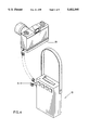
- FIG. 1 is a pictorial illustration of the still video apparatus of the present invention in association with a conventional film camera;
- FIG. 2 is a simplified block diagram illustration of a still video system constructed and operative in accordance with one preferred embodiment of the invention
- FIG. 3 is a simplified block diagram illustration of a still video system constructed and operative in accordance with another preferred embodiment of the invention.
- FIG. 4 is a pictorial illustration of a still video system corresponding to the embodiment of FIG. 3;
- FIG. 5 is a pictorial layout illustration of the video module employed in accordance with a preferred embodiment of the present invention.
- FIG. 6 is a schematic illustration of an alternative embodiment of the present invention.
- FIG. 1 illustrates still video apparatus of the present invention in association with a conventional film camera.
- the camera 10 may be any suitable film camera such as a 35 mm single lens reflex camera.
- the still video apparatus of the invention comprises a video module 12, which is preferably in the overall configuration of conventional film for which the camera 10 is designed.
- the video module includes a first portion 14 which is shaped generally like a 35 mm film cartridge and a second portion 16, which is shaped generally like a section of film extending outwardly therefrom and lying in the focal plane of the camera.
- the video module 12 includes a detector array, such as a CCD array, which is disposed in the focal plane of the camera.
- the video module 12 may record an image whenever the shutter is opened and may be programmed to read out or store the image independently of the operation of the shutter and film drive.
- any suitable interconnection between the conventional camera controls and the video module 12 may be provided.
- An external control may also be provided to operate the image sensor circuits independently of the camera controls.
- FIG. 2 illustrates typical circuitry of the still video apparatus of the present invention.
- a power source such as a battery, provides electrical power for the entire apparatus.
- the image plane detector array comprises a CCD array operated by a CCD control circuit 24.
- the output of the CCD array 22 is supplied to signal processing circuitry 26, which in turn outputs via an A/D converter 28 to digital signal processing circuitry 30, which stores received images in a memory 32.
- Circuitry 26 and/or circuitry 30 may be operative for carrying out conventional image processing functions, such as changing the sensitivity of the CCD output as by division or multiplication of the CCD output values, and stretching or compressing the contrast boundaries of the CCD.
- Image outputs may be provided via a suitable signal port 34 to display and/or storage devices 36, such as video terminals, video recorders and televisions.
- display and/or storage devices 36 such as video terminals, video recorders and televisions.
- all of the circuitry and apparatus indicated within block 38 may be contained within the video module, which is preferably insertable in camera 10 without requiring any structural modification to the camera.
- FIGS. 3 and 4 illustrate an alternative embodiment of the apparatus of the present invention wherein part; of the circuitry and apparatus indicated within block 38 is incorporated in one or more auxiliary modules.
- the video module is indicated by reference numeral 50 and preferably includes a power supply 52, a CCD array 54, CCD control circuitry 56 and signal processing circuitry 58. According to one variation it may also include an A/D converter 60 and a transceiver 62. Alternatively, the A/D converter 60 and transceiver 62 may be eliminated.
- An auxiliary module 70 is also provided in the embodiment of FIGS. 3 and 4. Where a wireless link is provided with the video module 50, a transceiver 72 is provided, preferably in a housing 73 mounted at the bottom of the camera housing. In such a case, the auxiliary module 70 comprises two elements.
- a cable connection such as via a flat cable, may be provided between the signal processor 58 in video module 50 and an A/D converter 74 in auxiliary module 70.
- the output from either A/D converter 74 or transceiver 72 is supplied to digital signal processing circuitry 76 which interfaces with a memory 78, such as a solid state memory.
- the output of digital signal processing circuitry 76 is supplied either directly to a video drive circuit 80, which converts the signals to conventional format, or alternatively to either a digital diskette drive 82 or via a digital to analog converter 84 to an analog diskette drive 84.
- the auxiliary module 70 may include Facilities and controls to enable storage control and editing of the images received thereby.
- the video module preferably includes a CCD array 90 as well as surface mounted electronics 92 and 91, which may include memory as well as control and processing electronics.
- Portion 14 may include battery as well as additional electronics.
- FIG. 6 illustrates an alternative embodiment of the present invention utilizing a relatively small detector array.
- the camera labeled 100, comprises an interchangeable lens 102 for focusing light from a scene to be detected, an insertable detector array 104 similar to but smaller than detector array 22, and a field of view reducing adapter 106, typically comprising a lens 107, for reducing the field of view of lens 102 to match that of the small detector array 104.
- Detector array 104 typically is a 2/3" CCD whose inner diameter is typically 0.43 inches.
- the field of view reducing adapter 106 typically is connectable to a camera housing 108 housing detector array 104, typically via standard camera parts changing methods.
- the field of view reducing adaptor 106 is typically placed such that the lens 106 is located between lens 102 and detector array 104.
- lens 107 is operative to change the field of view a 1 of the lens 102 to a smaller field of view a 2 .
- a 1 is typically 47 degrees and, for a CCD of 2/3" format, a 2 is approximately 16 degrees. It will be appreciated that the value of a 2 is dependent on the optical design of the adapter 106 and lens 107.
- Camera 100 typically also comprises a mirror 110, selectively locatable between the adapter 106 and the detector 104, a focusing screen 111 and a prism 112 for providing an image of the scene to be detected in a viewfinder 114. Due to the field of view reducing adapter 106, the image seen in the viewfinder 114 typically has a small field of view.
- camera 100 can optionally comprise a field of view expanding adapter 116, typically comprising a lens 118, connectable between the viewfinder 114 and an eye 120 of a viewer, for expanding the field of view of the scene to a standard field of view.
- a field of view expanding adapter 116 typically comprising a lens 118, connectable between the viewfinder 114 and an eye 120 of a viewer, for expanding the field of view of the scene to a standard field of view.
- adapters 106 and 116 are typically insertable into a conventional film camera, such as camera 10.
Abstract
Description
Claims (24)
Priority Applications (1)
| Application Number | Priority Date | Filing Date | Title |
|---|---|---|---|
| US08/142,765 US5452000A (en) | 1991-05-07 | 1993-10-26 | Apparatus for electronic photography using a conventional film camera |
Applications Claiming Priority (3)
| Application Number | Priority Date | Filing Date | Title |
|---|---|---|---|
| US69677891A | 1991-05-07 | 1991-05-07 | |
| US07/935,017 US5282040A (en) | 1991-05-07 | 1992-08-25 | Apparatus for operating a film camera |
| US08/142,765 US5452000A (en) | 1991-05-07 | 1993-10-26 | Apparatus for electronic photography using a conventional film camera |
Related Parent Applications (1)
| Application Number | Title | Priority Date | Filing Date |
|---|---|---|---|
| US07/935,017 Continuation US5282040A (en) | 1991-05-07 | 1992-08-25 | Apparatus for operating a film camera |
Publications (1)
| Publication Number | Publication Date |
|---|---|
| US5452000A true US5452000A (en) | 1995-09-19 |
Family
ID=24798515
Family Applications (2)
| Application Number | Title | Priority Date | Filing Date |
|---|---|---|---|
| US07/935,017 Expired - Lifetime US5282040A (en) | 1991-05-07 | 1992-08-25 | Apparatus for operating a film camera |
| US08/142,765 Expired - Lifetime US5452000A (en) | 1991-05-07 | 1993-10-26 | Apparatus for electronic photography using a conventional film camera |
Family Applications Before (1)
| Application Number | Title | Priority Date | Filing Date |
|---|---|---|---|
| US07/935,017 Expired - Lifetime US5282040A (en) | 1991-05-07 | 1992-08-25 | Apparatus for operating a film camera |
Country Status (6)
| Country | Link |
|---|---|
| US (2) | US5282040A (en) |
| EP (1) | EP0583391B1 (en) |
| JP (1) | JP2601624B2 (en) |
| AU (1) | AU2024992A (en) |
| HK (1) | HK1004077A1 (en) |
| WO (1) | WO1992020007A1 (en) |
Cited By (7)
| Publication number | Priority date | Publication date | Assignee | Title |
|---|---|---|---|---|
| WO1998015116A1 (en) * | 1996-10-03 | 1998-04-09 | Photo Opto Electronic Technologies | Apparatus for digital photography using a conventional film camera |
| US5933670A (en) * | 1997-12-18 | 1999-08-03 | Eastman Kodak Company | Focal plane mounting for an image sensor |
| US6351282B1 (en) * | 1997-09-02 | 2002-02-26 | Intel Corporation | Method and apparatus for taking digital pictures with an industry standard film camera |
| US6393224B1 (en) * | 1999-07-16 | 2002-05-21 | Silicon Film Technologies, Inc. | E-film cartridge with sensor avoidance feature |
| US20030043278A1 (en) * | 2001-09-06 | 2003-03-06 | Fuji Photo Film Co., Ltd. | Shooting system and silver-salt camera |
| US20040085476A1 (en) * | 2002-07-11 | 2004-05-06 | Whalen Matthew Stephen | Electronic image capture system with modular components |
| US20040141088A1 (en) * | 2001-03-09 | 2004-07-22 | Schmidt Dominik J. | Systems and methods to reversibly convert a film-based camera into a digital camera |
Families Citing this family (20)
| Publication number | Priority date | Publication date | Assignee | Title |
|---|---|---|---|---|
| US5561458A (en) * | 1994-01-28 | 1996-10-01 | Polaroid Corporation | Electronic imaging module for reversibly converting a photographic camera into an electronic imaging camera |
| US20020082043A1 (en) * | 1994-05-19 | 2002-06-27 | Kari-Pekka Wilska | Device for personal communications, data collection and data processing, and a circuit card |
| WO1996036167A1 (en) * | 1995-05-10 | 1996-11-14 | Hitachi, Ltd. | Video signal processor and optical image converter therefor |
| GB9607770D0 (en) * | 1996-04-15 | 1996-06-19 | Euroquest Solutions Ltd | Imaging system |
| IL119227A0 (en) * | 1996-09-09 | 1996-12-05 | Scitex Corp Ltd | An image for standard camera bodies |
| US6564018B2 (en) | 1996-09-09 | 2003-05-13 | Creoscitek Corporation Ltd. | Imaging device for digital photography |
| FI104222B (en) * | 1996-10-03 | 1999-11-30 | Nokia Mobile Phones Ltd | Modular mobile communication system |
| DE59710523D1 (en) * | 1997-02-28 | 2003-09-11 | Sinar Ag Feuerthalen | Still camera with optional photographic or electronic image recording |
| US6181883B1 (en) * | 1997-06-20 | 2001-01-30 | Picostar, Llc | Dual purpose camera for VSC with conventional film and digital image capture modules |
| KR100653335B1 (en) * | 1997-07-22 | 2007-06-07 | 후지 샤신 필름 가부시기가이샤 | Electronic camera |
| US6370339B1 (en) | 1998-11-13 | 2002-04-09 | Silicon Film Technologies, Inc. | System and method for operating an electronic film camera |
| US6431768B1 (en) * | 1999-03-25 | 2002-08-13 | Ricoh Company, Ltd. | Digital camera having rotatable optical viewfinder unit |
| AU7626300A (en) * | 1999-07-27 | 2001-02-13 | Itzhak Sapir | Off-film metering system for electronic film cameras |
| WO2001097502A2 (en) * | 2000-06-15 | 2001-12-20 | Silicon Film Technologies, Inc. | Apparatus and method for packaging an electronic imager allowing use of maximum active surface |
| US20040201745A1 (en) * | 2001-09-28 | 2004-10-14 | Eastman Kodak Company | Camera using a memory card with an integrated electronic imager for digital capture |
| ES2199700B1 (en) * | 2003-10-27 | 2005-03-01 | Marc Guiu Ribera | DEVICE FOR THE DIGITALIZATION OF PHOTOGRAPHIC CAMERAS. |
| US7695503B1 (en) * | 2004-06-09 | 2010-04-13 | Biomet Sports Medicine, Llc | Method and apparatus for soft tissue attachment |
| ITRM20050277A1 (en) * | 2005-06-01 | 2005-08-31 | Mario Capuano | DIGITAL PHOTOGRAPHIC ROLLER FOR ANALOGUE MACHINES. |
| JP2007104116A (en) * | 2005-09-30 | 2007-04-19 | Fujifilm Corp | Film cartridge type digital camera |
| US20180011389A1 (en) * | 2016-07-11 | 2018-01-11 | Petrica-Sandel Baciu | Modular Instant and Digital Back for Film TLR Cameras |
Citations (13)
| Publication number | Priority date | Publication date | Assignee | Title |
|---|---|---|---|---|
| US4303322A (en) * | 1979-11-29 | 1981-12-01 | Canon Kabushiki Kaisha | Electronic image pick-up device for a single-lens reflex camera having an interchangeable finder |
| US4742369A (en) * | 1985-03-20 | 1988-05-03 | Casio Computer Co., Ltd. | Electronic still camera |
| US4814811A (en) * | 1986-12-05 | 1989-03-21 | Minolta Camera Kabushiki Kaisha | Still camera system |
| US4823199A (en) * | 1986-03-11 | 1989-04-18 | Minolta Camera Kabushiki Kaisha | Still video adapter device detachable to a camera body |
| US4862293A (en) * | 1986-08-30 | 1989-08-29 | Minolta Camera Kabushiki Kaisha | Still video adapter |
| US4885837A (en) * | 1988-01-13 | 1989-12-12 | Mitsubishi Denki Kabushiki Kaisha | Apparatus for forming leads of semiconductor devices |
| JPH0210874A (en) * | 1988-03-29 | 1990-01-16 | Sgs Thomson Microelettronica Spa | Method of manufacture of conductivity modulation mos semiconductor power device and device obtained by the method |
| US4916476A (en) * | 1989-02-14 | 1990-04-10 | Eastman Kodak Company | Method and circuit for converting a conventional camera into an electro-optical camera |
| US4929972A (en) * | 1987-05-15 | 1990-05-29 | Large Scale Biology | Method and apparatus for electronic and photographic image recording |
| US4933780A (en) * | 1988-10-07 | 1990-06-12 | Eastman Kodak Company | Camera apparatus for magnetically recording on film |
| US4949117A (en) * | 1988-12-23 | 1990-08-14 | Eastman Kodak Company | Camera |
| US4953029A (en) * | 1986-11-29 | 1990-08-28 | Minolta Camera Kabushiki Kaisha | Interchangeable film back or still video back still camera system |
| JPH02301378A (en) * | 1989-05-16 | 1990-12-13 | Minolta Camera Co Ltd | Still video back |
Family Cites Families (18)
| Publication number | Priority date | Publication date | Assignee | Title |
|---|---|---|---|---|
| US3883883A (en) * | 1972-09-22 | 1975-05-13 | Canon Kk | Remote control device for camera |
| JPS5647522U (en) * | 1979-09-17 | 1981-04-27 | ||
| US4420773A (en) * | 1980-06-30 | 1983-12-13 | Nippon Kogaku K.K. | Electronic photographic camera |
| GB2087194B (en) * | 1980-11-07 | 1985-09-11 | Victor Company Of Japan | Video signal recording/reproducing apparatus controllable via camera |
| JPS57173272A (en) * | 1981-04-17 | 1982-10-25 | Canon Inc | Video camera system |
| JPS57202512A (en) * | 1981-06-08 | 1982-12-11 | Olympus Optical Co Ltd | Diopter adjusting eyepiece |
| JPS5833369A (en) * | 1981-08-21 | 1983-02-26 | Sony Corp | Electronic camera |
| JPS5838935A (en) * | 1981-08-31 | 1983-03-07 | Canon Inc | Camera |
| US4591234A (en) * | 1982-01-27 | 1986-05-27 | Nippon Kogaku K. K. | Rear focus conversion lens |
| JPS58162947A (en) * | 1982-03-23 | 1983-09-27 | Max Co Ltd | Image pickup device |
| US4609272A (en) * | 1984-07-02 | 1986-09-02 | Canon Kabushiki Kaisha | Finder system of high image magnification |
| JPS6243613A (en) * | 1985-08-22 | 1987-02-25 | Canon Inc | Converter lens |
| JPH01261625A (en) * | 1988-04-13 | 1989-10-18 | Canon Inc | Camera system |
| JP2622583B2 (en) * | 1988-06-23 | 1997-06-18 | コニカ株式会社 | Structure incorporating still video mechanism in film camera |
| JPH01321782A (en) * | 1988-06-23 | 1989-12-27 | Konica Corp | Film camera loading electing still video photographing mechanism |
| JP2621446B2 (en) * | 1988-12-13 | 1997-06-18 | キヤノン株式会社 | Zoom finder |
| JPH02101447A (en) * | 1988-10-11 | 1990-04-13 | Konica Corp | Film camera attaching/detaching still video photographing mechanism |
| US5053794A (en) * | 1989-12-08 | 1991-10-01 | Benz William G | Universal adapter for attaching a camera to associated optical devices such as telescopes, microscopes and the like |
-
1992
- 1992-04-28 AU AU20249/92A patent/AU2024992A/en not_active Abandoned
- 1992-04-28 WO PCT/US1992/003543 patent/WO1992020007A1/en active IP Right Grant
- 1992-04-28 EP EP92912566A patent/EP0583391B1/en not_active Expired - Lifetime
- 1992-08-25 US US07/935,017 patent/US5282040A/en not_active Expired - Lifetime
- 1992-12-30 JP JP5511948A patent/JP2601624B2/en not_active Expired - Lifetime
-
1993
- 1993-10-26 US US08/142,765 patent/US5452000A/en not_active Expired - Lifetime
-
1998
- 1998-04-15 HK HK98103097A patent/HK1004077A1/en not_active IP Right Cessation
Patent Citations (13)
| Publication number | Priority date | Publication date | Assignee | Title |
|---|---|---|---|---|
| US4303322A (en) * | 1979-11-29 | 1981-12-01 | Canon Kabushiki Kaisha | Electronic image pick-up device for a single-lens reflex camera having an interchangeable finder |
| US4742369A (en) * | 1985-03-20 | 1988-05-03 | Casio Computer Co., Ltd. | Electronic still camera |
| US4823199A (en) * | 1986-03-11 | 1989-04-18 | Minolta Camera Kabushiki Kaisha | Still video adapter device detachable to a camera body |
| US4862293A (en) * | 1986-08-30 | 1989-08-29 | Minolta Camera Kabushiki Kaisha | Still video adapter |
| US4953029A (en) * | 1986-11-29 | 1990-08-28 | Minolta Camera Kabushiki Kaisha | Interchangeable film back or still video back still camera system |
| US4814811A (en) * | 1986-12-05 | 1989-03-21 | Minolta Camera Kabushiki Kaisha | Still camera system |
| US4929972A (en) * | 1987-05-15 | 1990-05-29 | Large Scale Biology | Method and apparatus for electronic and photographic image recording |
| US4885837A (en) * | 1988-01-13 | 1989-12-12 | Mitsubishi Denki Kabushiki Kaisha | Apparatus for forming leads of semiconductor devices |
| JPH0210874A (en) * | 1988-03-29 | 1990-01-16 | Sgs Thomson Microelettronica Spa | Method of manufacture of conductivity modulation mos semiconductor power device and device obtained by the method |
| US4933780A (en) * | 1988-10-07 | 1990-06-12 | Eastman Kodak Company | Camera apparatus for magnetically recording on film |
| US4949117A (en) * | 1988-12-23 | 1990-08-14 | Eastman Kodak Company | Camera |
| US4916476A (en) * | 1989-02-14 | 1990-04-10 | Eastman Kodak Company | Method and circuit for converting a conventional camera into an electro-optical camera |
| JPH02301378A (en) * | 1989-05-16 | 1990-12-13 | Minolta Camera Co Ltd | Still video back |
Cited By (14)
| Publication number | Priority date | Publication date | Assignee | Title |
|---|---|---|---|---|
| US20030103147A1 (en) * | 1996-10-03 | 2003-06-05 | Schmidt Dominik J. | Photocard that is inserted into a non-digital camera to enable the non-digital camera to take digital photographic images |
| US7023467B2 (en) | 1996-10-03 | 2006-04-04 | Gallitzin Allegheny Llc | Photocard that is inserted into a non-digital camera to enable the non-digital camera to take digital photographic images |
| US6278481B1 (en) | 1996-10-03 | 2001-08-21 | Airify Communications, Inc. | Photocard that is inserted into a non-digital camera to enable the non-digital camera to take digital photographic images |
| WO1998015116A1 (en) * | 1996-10-03 | 1998-04-09 | Photo Opto Electronic Technologies | Apparatus for digital photography using a conventional film camera |
| US6351282B1 (en) * | 1997-09-02 | 2002-02-26 | Intel Corporation | Method and apparatus for taking digital pictures with an industry standard film camera |
| US5933670A (en) * | 1997-12-18 | 1999-08-03 | Eastman Kodak Company | Focal plane mounting for an image sensor |
| US6393224B1 (en) * | 1999-07-16 | 2002-05-21 | Silicon Film Technologies, Inc. | E-film cartridge with sensor avoidance feature |
| US20040141088A1 (en) * | 2001-03-09 | 2004-07-22 | Schmidt Dominik J. | Systems and methods to reversibly convert a film-based camera into a digital camera |
| US6943820B2 (en) * | 2001-03-09 | 2005-09-13 | Gallitzin Allegheny Llc | Systems and methods to reversibly convert a film-based camera into a digital camera |
| US20060024048A1 (en) * | 2001-03-09 | 2006-02-02 | Schmidt Dominik J | Systems and methods to reversibly convert a film-based camera into a digital camera |
| US7525569B2 (en) * | 2001-03-09 | 2009-04-28 | Gallitzin Allegheny Llc | Systems and methods to reversibly convert a film-based camera into a digital camera |
| US20030043278A1 (en) * | 2001-09-06 | 2003-03-06 | Fuji Photo Film Co., Ltd. | Shooting system and silver-salt camera |
| US7092627B2 (en) * | 2001-09-06 | 2006-08-15 | Fuji Photo Film Co., Ltd. | Shooting system and silver-salt camera |
| US20040085476A1 (en) * | 2002-07-11 | 2004-05-06 | Whalen Matthew Stephen | Electronic image capture system with modular components |
Also Published As
| Publication number | Publication date |
|---|---|
| EP0583391A1 (en) | 1994-02-23 |
| EP0583391B1 (en) | 1997-10-15 |
| AU2024992A (en) | 1992-12-21 |
| US5282040A (en) | 1994-01-25 |
| HK1004077A1 (en) | 1998-11-13 |
| WO1992020007A1 (en) | 1992-11-12 |
| JPH06507530A (en) | 1994-08-25 |
| EP0583391A4 (en) | 1994-04-06 |
| JP2601624B2 (en) | 1997-04-16 |
Similar Documents
| Publication | Publication Date | Title |
|---|---|---|
| US5452000A (en) | Apparatus for electronic photography using a conventional film camera | |
| US6278481B1 (en) | Photocard that is inserted into a non-digital camera to enable the non-digital camera to take digital photographic images | |
| US5438359A (en) | Electronic camera system using IC memory card | |
| US5040068A (en) | Electronic imaging apparatus with interchangeable pickup units | |
| US6630958B2 (en) | Method and apparatus for storing and displaying an image taken by a rotatable image pickup portion | |
| US5893037A (en) | Combined electronic/silver-halide image capture system with cellular transmission capability | |
| US6181883B1 (en) | Dual purpose camera for VSC with conventional film and digital image capture modules | |
| US5959669A (en) | Image pickup apparatus having standard-resolution and high-resolution photographing modes | |
| US20030112356A1 (en) | System and method for using a single intelligence circuit for a plurality of imaging rendering components | |
| JP3945052B2 (en) | Interchangeable lens electronic camera, interchangeable lens unit and camera body | |
| US7885537B1 (en) | Enlarged display for a camera viewfinder | |
| US7199830B1 (en) | Image pickup apparatus including selective insertion of ND filter into taking lens optical path based on luminance of object to be imaged | |
| JP2000175089A5 (en) | ||
| CN102098429A (en) | Photographic device and accessory device capable of assembly and disassembly thereon | |
| US20010028397A1 (en) | Camera | |
| US5895127A (en) | Data transmitting device | |
| US20040085476A1 (en) | Electronic image capture system with modular components | |
| JP2006251225A (en) | Photographing device and lens unit | |
| JP3012247B2 (en) | Electronic camera system | |
| JP3093252B2 (en) | Imaging device and adapter device | |
| JP3694942B2 (en) | Digital still camera | |
| JP2543740B2 (en) | Still video camera | |
| JP2627760B2 (en) | Still video camera and semiconductor memory unit for still video camera | |
| JP2000152040A (en) | Electronic camera system | |
| JPH01186069A (en) | Still video camera |
Legal Events
| Date | Code | Title | Description |
|---|---|---|---|
| FEPP | Fee payment procedure |
Free format text: ENTITY STATUS SET TO SMALL (ORIGINAL EVENT CODE: SMAL); ENTITY STATUS OF PATENT OWNER: SMALL ENTITY |
|
| STCF | Information on status: patent grant |
Free format text: PATENTED CASE |
|
| FEPP | Fee payment procedure |
Free format text: PAYOR NUMBER ASSIGNED (ORIGINAL EVENT CODE: ASPN); ENTITY STATUS OF PATENT OWNER: SMALL ENTITY |
|
| FPAY | Fee payment |
Year of fee payment: 4 |
|
| AS | Assignment |
Owner name: KNOBBE MARTENS OLSON & BEAR, LLP, CALIFORNIA Free format text: SECURITY INTEREST;ASSIGNOR:SILICON FILM TECHNOLOGIES;REEL/FRAME:011796/0374 Effective date: 20010416 |
|
| FPAY | Fee payment |
Year of fee payment: 8 |
|
| FEPP | Fee payment procedure |
Free format text: PAYER NUMBER DE-ASSIGNED (ORIGINAL EVENT CODE: RMPN); ENTITY STATUS OF PATENT OWNER: SMALL ENTITY Free format text: PAYOR NUMBER ASSIGNED (ORIGINAL EVENT CODE: ASPN); ENTITY STATUS OF PATENT OWNER: SMALL ENTITY |
|
| FPAY | Fee payment |
Year of fee payment: 12 |