US5555212A - Method and apparatus for redundancy word line replacement in a semiconductor memory device - Google Patents
Method and apparatus for redundancy word line replacement in a semiconductor memory device Download PDFInfo
- Publication number
- US5555212A US5555212A US08/306,438 US30643894A US5555212A US 5555212 A US5555212 A US 5555212A US 30643894 A US30643894 A US 30643894A US 5555212 A US5555212 A US 5555212A
- Authority
- US
- United States
- Prior art keywords
- data
- bit
- word line
- redundant
- memory cells
- Prior art date
- Legal status (The legal status is an assumption and is not a legal conclusion. Google has not performed a legal analysis and makes no representation as to the accuracy of the status listed.)
- Expired - Lifetime
Links
Images


Classifications
-
- G—PHYSICS
- G11—INFORMATION STORAGE
- G11C—STATIC STORES
- G11C29/00—Checking stores for correct operation ; Subsequent repair; Testing stores during standby or offline operation
- G11C29/70—Masking faults in memories by using spares or by reconfiguring
- G11C29/78—Masking faults in memories by using spares or by reconfiguring using programmable devices
- G11C29/84—Masking faults in memories by using spares or by reconfiguring using programmable devices with improved access time or stability
Definitions
- the present invention generally relates to a semiconductor memory device and, more particularly, to a method and apparatus for replacing defective memory cells in a semiconductor memory device using redundant memory cells.
- a semiconductor memory cell array includes a plurality of memory cells MC arranged in rows and columns and has a plurality of word lines WL 1 , WL 2 , . . . , and WL n which intersect bit line pairs BL 1 , BL 1 , BL 2 , BL 2 , . . . , and BL m , BL m .
- FIG. 1 A conventional arrangement is depicted in FIG. 1.
- Memory cells are located at intersections of word lines WL and bit lines of a plurality of bit line pairs.
- Each memory cell includes a capacitor for storing data and a MOS transistor for switching.
- a sense amplifier section 2 including a plurality of sense amplifiers is responsive to a column selection signal CSL and transfers data between selected memory cells and a data line pair DL, DL.
- An address buffer receives external address signals which are decoded by a row decoder 4 and a column decoder 6.
- the row decoder 4 supplies a word line selecting signal RSL to a word line driver 8 which drives a word line selected in accordance with the address signals.
- a column decoder 6 supplies the column selecting signal CSL to the sense amplifier section 2 to effect data transfer between the data lines DL, DL and the column selected in accordance with the addressed signals.
- FIG. 2 is a detailed depiction of a portion of the arrangement shown in FIG. 1.
- a word line WL i is connected to a gate of a MOS switching transistor Qs in a memory cell MC1.
- a data signal is transferred between the capacitor Cs of the memory cell MC1 and a bit line BL j connected to the memory cell MC1.
- the bit lines BL 3 and BL 3 of the illustrated bit line pair are precharged to a precharge voltage 1/2 Vdd (1/2 Vdd sensing).
- a word line WL j is connected to a gate of a MOS switching transistor Qs of in a memory cell MC2.
- a data signal is transferred between the capacitor Cs of the memory cell MC2 and a bit line BL j connected to the memory cell MC2.
- a bit line sense amplifier SA connected to the bit line pair BL j and BL j senses and amplifies this potential difference. As shown in FIG.
- sense amplifier SA includes a CMOS flip-flop connected between the bit lines BL j and BL j .
- the CMOS flip-flop which includes transistors Q1, Q2, Q3, and Q4 is connected via a PMOS transistor Q11 and an NMOS transistor Q12 to a power source Vdd and ground Vss, respectively.
- the gates of transistors Q11 and Q12 receive trigger signals S 0 and S 0 , respectively.
- a pair of NMOS transistors Q5 and Q6, connected between the bit lines BL j , BL j and the data lines DL, DL j form an input/output (I/O) gate. Responsive to a signal CSL j supplied from column decoder 6 (FIG. 1) to the I/O gate transistors Q5 and Q6, data signals are transferred between the bit lines BL j , BL j and the data lines DL, DL when the column j has been selected.
- One technique for dealing with this problem is to utilize redundant memory cells which are provided in a semiconductor memory device to replace memory cells which are determined to be defective during device testing. Accordingly, a word line or a bit line to which a defective memory cell is connected may be replaced by a redundant word line or redundant bit line connected to redundant memory cells. An address of a defective memory cell may be programmed by blowing appropriate ones of the fuses in a redundancy control circuit. A redundant memory cell is selected when an address corresponding to a defective memory cell is input.
- FIG. 3 illustrates a portion of a conventional dynamic random access memory with row redundancy.
- the memory portion includes memory cells MC1, MC2 and a redundant memory cell RMC1.
- the memory cells MC1 and MC2 are formed by a respective data storage capacitors Cs and transfer transistors Qs.
- Redundant memory cell RMC1 is formed by a data storage capacitor Cr and a transfer transistor Qr.
- the gates of the transfer transistors Qs, Qs of memory cells MC1, MC2 are connected to word lines WL i and WL j , respectively.
- the gate of the transfer transistor Qr of redundant memory cell RMC1 is connected to a redundant word line RDWL i .
- External address signals are supplied via an address buffer (not shown) to a row decoder which generates word line selecting signals RSLi, RSLj, . . . , etc.
- the word line selecting signals are supplied to word line driver WDR.
- the address buffer also forwards address signals to redundancy control circuit RRDN.
- RRDN generates word line drive signal WD and redundant word line drive signals RDWD1, RDWD2, . . . , RDWDj.
- WD is active when a memory cell on a normal word line is to be accessed.
- One of the redundant word line drive signals is active when a redundant memory cell on a redundant word line is to be accessed.
- RDWDj are forwarded to word line driver WDR and redundant word line driver RWDR, respectively.
- WDR includes an AND gate. At each AND gate WD is ANDed with the respective word line selecting signal.
- the word line WL i is driven by word line driver WDR, data may be read out or written to the data storage capacitor Cs of memory cell MC1 via bit line BLj.
- the word line WL j is driven by the word line driver WDR, data may be read out or written to the data storage capacitor Cs of the memory cell MC2 via the bit line BL j .
- the redundant memory cell RMC1 may replace either memory cell MC1 or MC2 if it is determined that one of these cells is defective.
- redundant memory cell RMC1 replaces the memory cell MC2
- the physical data stored in capacitor Cr of redundant memory cell RMC1 for representing a given logical data bit will be inverted with respect to the physical data stored in capacitor Cs of memory cell MC2 for representing the same given logical data bit.
- two logic states correspond to the arrangement and composition of the memory cell array. Half the memory cell array equals the true state of data to be read or written while the other half corresponds to the complementary state.
- the physical data state (i.e., bit pattern) in which a given bit is stored in a substituted redundant memory cell may differ (i.e., be inverted) from the physical data state in which that given bit is stored in the replaced memory cell.
- redundant memory cells can be substituted in a manner which ensures that the physical data states of the bit information stored in the redundant memory cells and the physical data state of bit information stored in the defective memory cells match.
- the efficiency of the redundancy cell is reduced with such an arrangement.
- FIG. 4a Shown in FIG. 4a are a word line driver 20, a memory cell array including a word line WL i , a redundant memory cell array including a redundant word line RDWL j , and a sense amplifier 30. According to this scheme, a redundant word line such as RDWL j may be substituted for a defective word line WL i .
- FIG. 4b having like elements to FIG. 4a
- four word lines are simultaneously replaced as a unit and accordingly the physical states of the original bit information is maintained.
- the efficiency of the scheme is reduced to 1/4 the efficiency of the FIG. 4a scheme using the same number of redundant word lines.
- the scheme would require four times the number of redundant word lines.
- This arrangement may be suitable for low density DRAMs, but as density increases, the number of redundant word lines and disadvantages also increase.
- the design space of the original bit increases in excess of 3% (6%) assuming an efficiency of four replaceable cells per 1 mega-bit (512 kilobits) sub-array used for a 256 mega-bit DRAM design. Higher efficiency would be expected for the 1 giga-bit DRAM or larger since the number of sub-arrays would be significantly greater increasing the probability of defective chips.
- the design space is thereby increased by more than 6% (12%) with an efficiency of 8 replaceable cells per 1 mega-bit (8 per 512 kilo-bits) of memory.
- the present invention overcomes the disadvantages associated with the aforementioned schemes. For example, improvements in testing time and redundancy efficiency, and a reduction in design space requirements can be achieved with the present invention.
- An illustrative semiconductor device includes memory cells arranged in rows and columns, the memory cells including normal memory cells and redundant memory cells for replacing defective ones of the normal memory cells.
- Bit line pairs are connected to the memory cells, each bit line pair consists of first and second bit lines which are respectively connected to memory cells in a corresponding one of the columns.
- the word lines include normal word lines each respectively connected to normal memory cells in a corresponding one of the rows and redundant word lines each respectively connected to redundant memory cells in a corresponding one of the rows.
- a data line pair consisting of first and second data lines for inputting/outputting complementary data signals to/from the bit line pair.
- a data flip circuit selectively flips the data signals on the first and second I/O lines.
- the semiconductor memory device can further include sense amplifiers each respectively connected to a corresponding one of the bit line pairs for amplifying a potential difference between the first and second bit lines of the respectively corresponding one of the bit line pairs.
- a data flip decoder generates a data flip control signal, the data flip decoder supplying the data flip control signal to the data flip circuit wherein the data flip circuit flips the data signals according to the data flip control signal.
- the data flip circuit includes a data input buffer for receiving a data input bit, the data input bit being flipped when the data flip control signal is active during a write operation, and forwarding a representation of the flipped or unflipped data input bit to the first and second data lines.
- the data flip circuit includes a data output buffer, coupled to the first and second data lines, which receives a data output bit representing bit information on the first and second data lines, the data output bit being flipped when the data flip control signal is active during a read operation, and reading out one of the flipped or unflipped data output bit.
- the design space is minimized and testing times are reduced while maintaining original physical data information.
- test times can be reduced. For example, test times can be reduced by half for which only physical-one or physical-zero data are tested for an NMOS or PMOS array, respectively.
- the test time of the signal margin can also be cut in half because the margin of the physical-one or physical-zero data can be tested by applying only a higher or a lower reference voltage to the reference cell or bit line.
- FIG. 1 shows a conventional semiconductor memory architecture
- FIG. 2 shows a more detailed conventional semiconductor memory architecture according to FIG. 1;
- FIG. 3 illustrates a portion of a conventional dynamic random access memory with row redundancy and a row redundancy control circuit
- FIGS. 4a and 4b show respective conventional row redundancy architectures
- FIG. 5 shows a memory array configuration for a semiconductor memory device with a row redundancy architecture according to the present invention
- FIG. 6 shows a detailed portion of the semiconductor device of FIG. 5;
- FIG. 7 shows a more detailed representation of the portion of the semiconductor device shown in FIG. 6 according to a first embodiment of the present invention
- FIG. 8a shows a fuse latch section in the redundancy control circuit depicted in FIG. 7;
- FIG. 8b shows a comparator in the redundancy control circuit depicted FIG. 7;
- FIG. 9 shows a more detailed representation of the data flip circuit depicted in FIG. 5;
- FIG. 10a shows a data flip decoder according to a second embodiment of the present invention
- FIG. 10b shows a bit line/word line architecture employed in the second embodiment of the present invention.
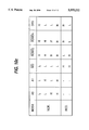
- FIG. 10c shows a logic table associated with the data flip decoder of the second embodiment of the present invention.
- the present invention is discussed below with reference to a dynamic random access memory (DRAM).
- DRAM dynamic random access memory
- the present invention may be applied to other types of semiconductor memory devices.
- the following invention is particularly developed for a DRAM using half-pitch non-twisting bit lines, but is also applicable to any DRAM or architecture such as twisted bit lines or a quarter pitch layout.
- FIG. 5 illustrates a semiconductor memory device including a memory cell array having a normal memory cell array portion 101 and a redundant memory cell array portion 102.
- Normal memory cell array portion 101 includes normal memory cells MC connected to word lines WL 1 , WL 2 , . . . , WL n and bit line pairs BL 1 , BL 1 , . . . , BL m , BL m .
- the redundant memory cell array portion 102 includes redundant memory cells RMC connected to redundant word lines RDWL 1 , RDWL 2 , . . . , RDWL p and bit line pairs BL 1 , BL 1 , . . . , BL m , BL m .
- the redundant word lines are used to replace ones of the word lines WL 1 , WL 2 , . . . , WL n which are determined to be defective during device testing.
- a bit line sense amplifier section 100 includes a plurality of sense amplifiers 103-1 to 103-m each of which is respectively connected to a corresponding one of the bit line pairs BL 1 , BL 1 , . . . , BL m , BL m .
- the sense amplifiers 103-1 to 103-m each sense and amplify potential differences between the bit lines of the corresponding bit line pair.
- the data lines DL, DL are connected to the sense amplifiers 103-1 to 103-m via I/O gates 104.
- the I/O gates 104 are responsive to column select signals CSL for inputting/outputting data to/from the memory cell array.
- Bit line pre-charge/equalize circuitry 95 equalizes the bit lines of each of the bit line pairs and pre-charges the bit lines to a predetermined voltage.
- An address buffer 50 receives external address signals and outputs internal address signals which are strobed into a redundancy control circuit (RRDN) 105, a row decoder 106, and a column decoder 120.
- the row decoder 106 decodes address signals and generates word line selecting signal RSL.
- RRDN 105 enables either a signal WD to a word line driver 110 for driving one of word lines WL 1 , WL 2 , . . . , WL n or a signal RDWD to a redundant word line driver 115 for driving one of redundant word lines RDWL 1 , RDWL 2 , . . . , RDWL p .
- the column decoder 120 decodes address signals strobed therein and outputs column select signals CSL to select one of the I/O gates 104 determined by the decoded address, whereby data may be transferred to/from the data lines DL, DL and the sense amplifier connected to the selected I/O gate.
- a data line precharge circuit 125 precharges the data lines DL, DL.
- RRDN 105 also generates data flip enable signals FL which are forwarded to data flip decoder 107. Based on the data flip enable signals FL, data flip decoder 107 generates a data flip signal DFS. Responsive to the data flip signal DFS generated by data flip decoder 107, a data flip circuit 130 selectively flips or inverts the signals on the data lines DL, DL.
- some of the normal memory cells MC will store data whose physical and logical states are the same and other normal memory cells will store data whose physical and logical states are complementary.
- the normal memory cells MC connected to the bit lines BL 1 , BL 2 , . . . , BL m to store logical "1" data physical data "1" is written thereto and in order for normal memory cells MC connected to bit lines BL 1 , BL 2 , . . . , BL m to store logical data "1", physical data "0" is written thereto.
- the word line WL i could be replaced by one of the redundant word lines RDWL 1 , RDWL 2 , . . . , RDWL p . If the defective word line WL i is replaced by the redundant word line RDWL j , the physical data state of the redundant memory cells RMC accessed by redundant word line RDWL j is the same as the physical data state of the normal memory cells MC accessed by word line WL i . Thus, if the physical data state of the normal memory cells MC coupled to word line WL i were 1, 0, . . .
- the physical data state of the redundant memory cells RMC coupled to the redundant word line RDWL j would be 1, 0, . . . , 1.
- the physical data state of the redundant memory cells RMC accessed by the redundant word line RDWL k is complementary to the physical data state of the normal memory cells MC accessed by the word line WL i .
- the physical data state of the redundant memory cells RMC coupled to the redundant word line RDWL k would be 0, 1, ..., 0.
- the data flip circuit 130 is responsive to a data flip signal DFS for flipping or inverting the signals on the data lines DL, DL when data is read from or written to a memory cell MC connected to a redundant word line such as RDWLk which has replaced a normal word line such as WL i .
- RDWLk redundant word line
- the physical data stored in the redundant memory cells RMC matches the physical data which would be stored in the normal memory cells MC.
- the data flip circuit 130 is further responsive to the data flip signal DFS for not flipping or inverting the signals on the data lines DL, DL when data is read from or written to a memory cell connected to a redundant word line such as RDWL j which has replaced a normal word line such as WL i . No flipping is required in the second instance since the physical data stored in the redundant memory cells RMC matches the physical data which would be stored in the normal memory cells MC.
- FIG. 6 is a more detailed representation of a portion of circuitry in FIG. 5 including data flip circuit 130, RRDN 105, and data flip decoder 107.
- RRDN 105 receives the row address and generates appropriate redundant word line drive signals RDWDj and RDWDk and data flip enable signals FLj and FLk in accordance with whether the row address corresponds to a defective normal word line which has been replaced by one of the redundant word lines. The generation of FLj and FLk will be described in greater detail below. Redundant word line drive signals RDWDj and RDWDk for driving the redundant word lines RDWL j and RDWL k , respectively, are shown in FIG. 6.
- the data flip decoder 107 receives data flip enable signals FLj and FLk from RRDN 105.
- the data flip enable signals FLj and FLk indicate whether the physical state of data stored in memory cells connected to a redundant word line is the same as the physical state of data stored in memory cells connected to a defective normal word line when RRDN 105 is enabled.
- the data flip decoder 107 By decoding the data flip enable signals, the data flip decoder 107 generates a control signal DFS.
- the data flip circuit 130 includes a data input buffer 180 which receives input data DI, a data output buffer 190 which outputs output data DO, and a data line sense amplifier 200.
- the control signal DFS is supplied to the data input buffer 180 and to the data output buffer 190.
- data input buffer 180 flips or inverts the signals supplied to data lines DL, DL.
- data output buffer 190 flips or inverts the signals supplied from data lines DL, DL.
- FIG. 7 shows a more detailed representation of RRDN 105 and data flip decoder 107 depicted in FIG. 6 according to a first embodiment of the present invention.
- RRDN 105 includes row redundancy control sections RRDNj and RRDNk which are each supplied with a row address.
- a typical row redundancy control circuit includes a plurality of row redundancy control sections similar to RRDNj and RRDNk. For example, each row redundancy control section corresponds to a particular row or word line address.
- the row redundancy control sections RRDNj and RRDNk generate redundant word line drive signals RDWD j and RDWD k via comparators 143a and 143b, respectively, for selecting redundant word lines RDWL j and RDWL k when the row address represents the address of a defective normal word line which has been replaced by these redundant word lines.
- Fuse sections 144a and 144b in the redundancy control sections RRDNj and RRDNk contain fuse latches (e.g., FL0, FL1, . . . ) and fuses which are appropriately blown by a laser, for example, to program the address of a selected word line. All the fuse latches FL0, FL1, . . .
- Normal operation has two operating modes, redundancy mode and normal mode (i.e., non-redundancy mode).
- a master fuse (not shown), one corresponding for each row redundancy control section, has not been blown, for example during a test operation, indicating normal mode.
- a master fuse in one of the row redundancy control section has been blown during a test operation indicating redundancy mode is to be implemented. Accordingly, a defective word line is replaced by a redundant word line during normal operation redundancy mode.
- the address of the selected word line is identified by the state (i.e., blown or not blown) of the fuses in each fuse section 144a and 144b. In the example shown in FIG.
- fuse latch state signals FOTj and F1Tj are output from fuse section 144a in redundancy control section RRDNj and fuse latch state signals F0Tk and F1Ck are output from fuse section 144b in row redundancy control section RRDNk.
- the row redundancy control sections RRDNj and RRDNk further include exclusive NOR (XNOR) gates 151 and 152, respectively and NOR gates 153 and 154, respectively.
- the XNOR gate 151 receives signals FOTj and F1Tj from fuse section 144a and supplies the logic result to a first input of NOR gate 153.
- a second input of NOR gate 153 is supplied with redundant word line drive signal RDWDj and NOR gate 153 generates a data flip enable signal FLj based on the logic result of XNOR gate 151 and redundant word line drive signal RDWDj.
- XNOR gate 152 receives signals FOTk and F1Ck from fuse section 144b and supplies the logic result to a first input of NOR gate 154.
- a second input of NOR gate 154 is supplied with the redundant word line drive signal RDWDk and NOR gate 154 generates a data flip enable signal FLk based on the logic result of XNOR gate 152 and redundant word line drive signal RD
- the data flip decoder 107 includes CMOS transistors 155 and 157, and a precharge MOS transistor 156.
- the data flip enable signals FLj and FLk from RRDN 105 are input to the gates of CMOS transistors 155 and 157, respectively.
- CMOS transistors 155 and 157 are part of a dynamic NOR scheme. However, it is to be understood that a static NOR scheme may also be used.
- the terminals of the CMOS transistors 155 and 157 are connected between the control signal line 158 for the data flip control signal DFS and ground.
- the data flip decoder 107 supplies the data flip control signal DFS to the data flip circuit 130 (see FIG. 5).
- the data flip circuit 130 responds to an active data flip control signal DFS to flip the data signals on the data lines DL, DL.
- the data flip enable signals FLj and FLk are wired ORed on the control signal line 158.
- a precharging transistor 156 precharges control signal line 158 to a predetermined voltage such as Vdd.
- the precharge transistor 156 has its gate connected to receive a control pulse and its terminals connected between Vdd and the control signal line 158.
- RRDN 105 and data flip decoder 107 Examples of the operation of RRDN 105 and data flip decoder 107 will be discussed below with reference to FIGS. 5 and 7.
- redundant word line RDWLj replaces word line WLi which has been determined to be defective during device testing. Accordingly, the corresponding master fuse in redundancy control section RRDNj has been blown indicating redundancy mode. It can be seen with reference to FIG. 5 that the physical state of data stored in the memory cells connected to redundant word line RDWLj is the same as the physical state of the data stored in the memory cells connected to normal word line WLi.
- fuse latch state signals FOTj fuse 0 true
- F1Tj fuse 1 true
- the output signals FOTj and F1Tj are supplied to XNOR gate 151. Since FOTj and F1Tj are both low, the logic result of the XNOR operation carried out by XNOR gate 151 is high.
- the NOR gate 153 receives the high output from XNOR gate 151 and the redundant word line drive signal RDWDj. The data flip enable signal FLj output from NOR gate 153 will be low even when the redundant word line drive signal RDWDj selects the redundant word line RDWLj.
- redundant word line RDWLk replaces word line WLi which has been determined to be defective during device testing. It can be seen with reference to FIG. 5 that the physical bit information stored in the memory cells connected to redundant word line RDWLk is complementary to the physical bit information stored in the memory cells connected to normal word line WLi.
- fuse latch state signals F0Tk and F1Ck from fuse latches FL0 and FL1 of RRDNk are low and high, respectively.
- the output signals F0Tk and F1Ck are supplied to XNOR gate 152. Since F0Tk and F1Ck are low and high, respectively, the logic result of the XNOR operation carried out by XNOR gate 152 is low.
- the NOR gate 154 receives the low output from XNOR gate 152 and the redundant word line drive signal RDWDk. In this case, data flip enable signal FLk output from NOR gate 154 will be high when redundant word line drive signal RDWDk selects redundant word line RDWLk.
- data flip circuit 130 flips the signals on data lines DL, DL. That is, since the physical state of data stored in the memory cells coupled to redundant word line RDWLj is complementary to the physical state of data stored in memory cells coupled to word line WLi, the bit information in the memory cells connected to redundant word line RDWLj does not match the bit information which would be stored in the memory cells connected to defective normal word line WLi. Accordingly, data flip circuit 130 flips the data lines DL, DL to maintain consistency between the bit information.
- FIGS. 8a and 8b show a more detailed representation of an exemplary row redundancy control section.
- FIG. 8a shows an illustrative fuse latch circuit (FLx) which is utilized in fuse sections 144a and 144b shown in FIG. 7 and may be used for the each master fuse as well.
- Fuse latch circuit FLx includes two MOS transistors 145 and 146, and an inverter 147.
- the MOS transistors 145 and 146 each have a first terminal connected to a power source voltage Vdd and a second terminal connected to fuse Fx.
- the gate of MOS transistor 145 receives a power pulse PWR and the gate of MOS transistor 146 is driven by the fuse latch state signal FxT which is output by inverter 147.
- the input terminal of the inverter 147 is coupled to the second terminals of MOS transistors 145 and 146, and to fuse Fx.
- Fuse Fx may be a fuse capable of being blown by a laser.
- fuse latch circuit FLx Responsive to the power pulse signal PWR supplied to the gate of the MOS transistor 145, fuse latch circuit FLx generates the fuse latch state signals FxT and FxC which represent the state of the corresponding fuse Fx. If the fuse Fx is blown, then FxT would be low and FxC would be high. If the fuse Fx is not blown, then FxT would be high and FxC would be low.
- FIG. 8b represents an illustrative comparator such as 143a shown in FIG. 7.
- An address bit Ax is supplied to the exemplary comparator portion of FIG. 8b.
- the address bit Ax is inverted by an inverter 162 and supplied to a first input of NOR gate 163.
- Address bit Ax is also supplied to a first input of NOR gate 164.
- a row address strobe RAS signal is supplied to a second input of NOR gate 163 and to a second input of NOR gate 164.
- NOR gates 163 and 164 generate signals AxC (address bit complement) and AxT (address bit true), respectively, when the row address strobe signal RAS is active.
- the AxC signal When generated, the AxC signal is supplied to CMOS transistor pair, NMOS transistor 165 and PMOS transistor 166, and the AxT signal is supplied to CMOS transistor pair, NMOS transistor 167 and PMOS transistor 168.
- the signal FxT is supplied to the gates of transistors 166 and 167 and the signal FxC is supplied to the gates of transistors 165 and 168. If the fuse Fx is blown (i.e., FxC high), the output signal AxI 0 from the CMOS transistor arrangement is AxC. If the fuse Fx is not blown, the output signal AxI 0 from the CMOS transistor arrangement is AxT.
- the signal AxI 0 is supplied to a NOR circuit 169 which receives signals (AxI 0 , AxI 1 , ... AxI n ) from each of the CMOS transistor arrangements in the comparator circuit and the corresponding master fuse signal FmTj from a master fuse latch circuit.
- Each of the signals AxI 0 , AxI 1 , . . . AxI n corresponds to a respective address bit (A 0 -A n ) of a word line address and the master fuse indicates the applicable mode of normal operation, that is redundancy mode or normal mode.
- NOR circuit 169 generates a word line drive signal WDj.
- the word line drive signal WDj is input to an OR gate 171 where it is ORed with the word line drive signals (WD1, WD2, . . . , WDj) from each comparator circuit to generate a word line drive signal WD which enables the word line driver 110 shown in FIG. 5. That is, when all the word line drive signals ORed are active (low), then the word line drive signal WD is low and active and the system is in normal mode. Otherwise, if one of the word line drive signals ORed is high then the system is in redundancy mode and word line drive signal WD is high and inactive.
- NOR gate 169 When the corresponding master fuse FmTj input to NOR gate 169 is not blown (FmTj is high), then normal mode is selected and the word line drive signal WDj is low regardless of the address. However, if the master fuse FmTj is blown (i.e., FmTj is low), then the NOR gate 169 will indicate redundancy mode depending on the signals AxI 0 , AxI 1 , . . . AxI n input. More specifically, when the signals AxI 0 , AxI 1 , . . . AxI n are all low, a proper address has been input to the NOR gate 169 and the word line drive signal WDj is high and inactive (i.e., redundancy mode).
- the word line drive signal WDj is supplied to a first input of a NAND gate 170 which generates the redundant word line drive signal RDWDj.
- the row address strobe signal RAS is supplied to a second input of NAND gate 170. If the signal WDj falls (normal word line access) before RAS rises, the redundant word line drive signal RDWDj output from the NAND gate 170 remains high, disabling redundancy mode. Redundancy mode is only enabled when the redundant word line drive signal RDWDj output from NAND gate 170 goes low. This occurs when the word line drive signal WDj remains high and RAS is high and active.
- FIG. 9 is a more detailed representation of the data flip circuit 130 of FIG. 5.
- the control signal DFS is supplied from data flip decoder 107 to data input buffer 180 and data output buffer 190.
- a low (active) control signal DFS triggers the data on the data lines DL, DL to be flipped during the read and write operations.
- an XNOR gate 181 receives the DFS control signal at a first input and input data DI at a second input.
- the state of the data input bit is flipped (i.e., either from 1 to 0 or from 0 to 1), and when DFS is inactive the state of the data input remains the same.
- the logic output of the XNOR gate 181 is either the flipped data input bit when DFS is low or the data input bit when DFS is high.
- the logic output of XNOR gate 181 is forwarded to an inverter 182 which inverts the logic output and supplies the inverted logic output to a first output of NOR gate 183.
- NOR gate 183 NORs the inverted logic output with the write enable signal WE.
- the logic output of XNOR gate 181 is supplied to a NOR gate 184 where it is NORed with the write enable signal WE.
- the outputs of the NOR gates 183 and 184 are respectively supplied to the gates of MOS transistors 185 and 186.
- the terminals of the transistor 185 are connected between the data line DL and ground and the terminals of transistor 186 are connected between the data line DL and ground.
- the write enable signal WE becomes active (low). Therefore, when the write enable signal WE is active, one of the MOS transistors 185, 186 will be turned on, thereby pulling the attached data line, DL or DL, low.
- the bit information on the data line DL is the complement of the data input bit.
- the bit information on the data lines DL, DL is forwarded to the memory cells via the bit lines BL and BL.
- WE When WE is high, no bit information is provided to the data lines DL, DL.
- the DFS control signal is also supplied to the data output buffer 190.
- the row decoder 106 through word line selecting signal RSL sent to word line driver 110, selects one of the word lines WL i causing its potential to increase. Charge stored in the memory cells connected to the selected word line is read out to the corresponding bit lines.
- the bit line sense amplifiers in the sense amplifier section 100 are activated to sense and amplify small potential differences between the bit lines of the bit line pairs.
- the complementary data from one of the sense amplifiers is coupled to the data lines DL, DL.
- the data on the data lines DL, DL is input to the data line sense amplifier 200 which obtains a single bit of information and outputs the information bit via a data output buffer 190 in accordance with the DFS signal.
- the data line precharge circuit 125 shown in FIG. 5 precharges the data lines DL, DL to Vdd.
- the bit output from the data line sense amplifier 200 and the DFS control signal are forwarded to an XNOR gate 192 in data output buffer 190.
- the logic output of the XNOR gate 192 is a flipped representation of the bit output from the data line sense amplifier 200.
- the logic output is the output bit of the data line sense amplifier 200.
- the logic output is then forwarded to a NOR gate 194 which also receives the read enable signal RE for a read operation.
- the read enable signal RE is low, the logic output bit is supplied to an external device (not shown).
- the design space can be minimized because a single redundant word line can replace a defective normal word line whether or not it stores data in the same physical state as the defective normal word line.
- This allows a single redundancy word line element to be used to fix one defect without limiting efficiency, and thus reduces the design space. This is particularly important for large DRAMs of 256 Mb and beyond that require many redundancy word line elements or redundancy arrays.
- a data flip circuit is responsive to a data flip signal for flipping or inverting the signals on data lines DL, DL whenever data is read from or written to a memory cell.
- the same physical data may be stored in all normal memory cells MC and all the redundant memory cells RMC.
- all cells are adjusted to have the same bit pattern (T), i.e., to hold the same information in the same state, regardless of the row addresses of the memory cells.
- the data flip decoder 107 may be replaced by the data flip decoder 107' shown in FIG. 10a.
- data flip decoder 107' is adapted for a half pitch non-twisted bit line architecture shown in FIG. 10b with the word lines WL and redundant word lines RDWL.
- the bit pattern for the original memory cell array is determined by the row addresses A0 and A1 as represented by the logic table of FIG. 10c. More particularly, the bit pattern of the accessed cell is not true (C) when both A0 and A1 are of opposite state (i.e., low and high, or high and low).
- the word line drive signal WD when the semiconductor memory device performs an operation in the normal mode, the word line drive signal WD is active (low). Consequently, in the normal mode, the output of XNOR gate 212 is the opposite of the output of the NOR gate 214 and is the same as the DFS signal output from the NOR gate 216.
- the word line drive signal WD is supplied to the NOR gate 214 from the output of the NOR gate 169 (FIG. 8b) described above.
- the data lines are flipped only when the bit pattern on the accessed cell is not true (C).
- the output of NAND gate 218 is low permitting the row addresses A0 and A1 to control the DFS signal output from the NOR gate 216 as can be seen in the logic table of FIG. 10c.
- the redundant word line drive signals RDWDj and RDWDk are both high and inactive.
- the DFS control signal is fed to the circuit of FIG. 7, and data is flipped when the signal is active as discussed above.
- normal mode word line drive signal WD supplied from the NOR gate 169 (FIG. 8b) is inactive (high).
- a low signal output from the NOR gate 214 is fed to the NOR gate 216, and the output of the NAND gate 218 controls the generation of the DFS control signal.
- Each comparator (FIG. 8b) section may generate plural redundant word line drive signals.
- Each redundant word line drive signal RDWk (RDWDk 0 , RDWDk 1 , . . . , RDWDk n ) is generated by a NAND gate 162 as described with reference to FIG. 8b.
- NAND gate 218 only receives the redundant word line drive signals represented by RDWDk (RDWDk 0 , RDWDk 1 , . . . , RDWDk n ) which are the redundant word lines coupled to memory cells having a complementary bit pattern.
- RDWDk RDWDk 0 , RDWDk 1 , . . . , RDWDk n
- C the bit pattern of the memory cells coupled to the selected redundant word line which is replacing the defective memory cell is not true (C).
- Every redundant word line drive signal (RDWDj and RDWDk) is supplied from NAND gate 170 in FIG. 8b to the redundant word line driver 115 in FIG. 5, although only the complementary redundant word line drive signals RDWDk are input to NAND gate 218.
- the redundant word line drive signal RDWDk represents whether true (T) bit pattern memory cells are coupled to the selected redundant word line when in redundancy mode. If all the signals RDWDk are high, then true bit pattern memory cells are coupled to the selected redundant word line. Accordingly, the output of the NAND gate 218 is low and the DFS control signal is high (i.e., inactive) and the data lines will not be flipped. When a redundant word line coupled to memory cells having a complementary bit pattern has been selected to replace a defective word line, the output of the NAND gate 218 is high thereby forcing the DFS control signal generated by the NOR gate 216 low. Thereafter, the data lines DL, DL are flipped in accordance with the description of FIG. 9 provided above.
- the second embodiment provides several advantages in addition to the advantages in the first embodiment.
- data is read from and written to each memory cell.
- the data lines are always flipped.
- the same bit data i.e., ⁇ 0 ⁇
- the same bit data can be supplied to every memory cell rather than supplying a ⁇ 0 ⁇ to the true bit pattern memory cells and supplying a ⁇ 1 ⁇ to the complementary bit pattern memory cells.
- T bit pattern
- testing of memory cells can be carried out in one step using a single data bit rather than in two steps in which opposite data must be respectively supplied for memory cells with true and complementary bit patterns.
- programming and testing time can be reduced with the second embodiment. Addressing problems are also eliminated because the same data is supplied to every cell and design space can be further minimized.
Abstract
Description
Claims (32)
Priority Applications (2)
| Application Number | Priority Date | Filing Date | Title |
|---|---|---|---|
| US08/306,438 US5555212A (en) | 1994-09-19 | 1994-09-19 | Method and apparatus for redundancy word line replacement in a semiconductor memory device |
| JP7240339A JP2994241B2 (en) | 1994-09-19 | 1995-09-19 | Semiconductor memory device and test method therefor |
Applications Claiming Priority (1)
| Application Number | Priority Date | Filing Date | Title |
|---|---|---|---|
| US08/306,438 US5555212A (en) | 1994-09-19 | 1994-09-19 | Method and apparatus for redundancy word line replacement in a semiconductor memory device |
Publications (1)
| Publication Number | Publication Date |
|---|---|
| US5555212A true US5555212A (en) | 1996-09-10 |
Family
ID=23185281
Family Applications (1)
| Application Number | Title | Priority Date | Filing Date |
|---|---|---|---|
| US08/306,438 Expired - Lifetime US5555212A (en) | 1994-09-19 | 1994-09-19 | Method and apparatus for redundancy word line replacement in a semiconductor memory device |
Country Status (2)
| Country | Link |
|---|---|
| US (1) | US5555212A (en) |
| JP (1) | JP2994241B2 (en) |
Cited By (42)
| Publication number | Priority date | Publication date | Assignee | Title |
|---|---|---|---|---|
| US5724366A (en) * | 1995-05-16 | 1998-03-03 | Mitsubishi Denki Kabushiki Kaisha | Semiconductor memory device |
| US5754486A (en) * | 1997-02-28 | 1998-05-19 | Micron Technology, Inc. | Self-test circuit for memory integrated circuits |
| US5761139A (en) * | 1995-12-08 | 1998-06-02 | Kabushiki Kaisha Toshiba | Semiconductor memory having redundancy memory cells |
| US5784321A (en) * | 1995-12-26 | 1998-07-21 | Sony Corporation | Semiconductor memory device with redundant circuit |
| US5953266A (en) * | 1996-12-31 | 1999-09-14 | Micron Technology, Inc. | Device and method for repairing a memory array by storing each bit in multiple memory cells in the array |
| US5963489A (en) * | 1998-03-24 | 1999-10-05 | International Business Machines Corporation | Method and apparatus for redundancy word line replacement in a repairable semiconductor memory device |
| US5966339A (en) * | 1998-06-02 | 1999-10-12 | International Business Machines Corporation | Programmable/reprogrammable fuse |
| US6003148A (en) * | 1996-05-30 | 1999-12-14 | Mitsubishi Denki Kabushiki Kaisha | Semiconductor memory device allowing repair of a defective memory cell with a redundant circuit in a multibit test mode |
| US6023434A (en) * | 1998-09-02 | 2000-02-08 | Micron Technology, Inc. | Method and apparatus for multiple row activation in memory devices |
| US6026038A (en) * | 1996-09-23 | 2000-02-15 | Samsung Electronics Co., Ltd. | Wafer burn-in test circuit and method for testing a semiconductor memory |
| US6094384A (en) * | 1998-06-29 | 2000-07-25 | Hyundai Electronics Industries Co., Ltd. | Column redundancy circuit |
| US6157582A (en) * | 1997-11-17 | 2000-12-05 | Cypress Semiconductor Corporation | Dynamic pull-up suppressor for column redundancy write schemes with redundant data lines |
| US6262922B1 (en) * | 1999-04-01 | 2001-07-17 | Kabushiki Kaisha Toshiba | Semiconductor memory device |
| US6337815B1 (en) * | 1998-07-30 | 2002-01-08 | Oki Electric Industry Co., Ltd. | Semiconductor memory device having redundant circuit |
| US20020056071A1 (en) * | 1998-01-29 | 2002-05-09 | Artisan Components, Inc. | Memories having reduced bitline voltage offsets |
| US20020162062A1 (en) * | 2001-04-25 | 2002-10-31 | Hughes Brian William | Device to inhibit duplicate cache repairs |
| US6542973B2 (en) * | 2001-07-03 | 2003-04-01 | Ibm Corporation | Integrated redundancy architecture system for an embedded DRAM |
| US6549476B2 (en) | 2001-04-09 | 2003-04-15 | Micron Technology, Inc. | Device and method for using complementary bits in a memory array |
| US20030071295A1 (en) * | 1995-09-20 | 2003-04-17 | Micron Technology, Inc. | Semiconductor memory circuitry |
| US6570793B2 (en) * | 2000-08-08 | 2003-05-27 | Infineon Technologies Ag | Semiconductor memory having a redundancy circuit for word lines and method for operating the memory |
| US20040027880A1 (en) * | 2002-08-08 | 2004-02-12 | Fujitsu Limited | Memory circuit with redundant memory cell array allowing simplified shipment tests and reduced power consumptions |
| US20040044935A1 (en) * | 2002-09-04 | 2004-03-04 | Vancura Mark D. | Method and apparatus for improved integrated circuit memory testing |
| US6728910B1 (en) * | 2000-09-20 | 2004-04-27 | Lsi Logic Corporation | Memory testing for built-in self-repair system |
| US20040090814A1 (en) * | 2002-11-11 | 2004-05-13 | Kazuhiko Takahashi | Semiconductor memory device |
| US20040179412A1 (en) * | 2003-03-13 | 2004-09-16 | Infineon Technologies North America Corp. | Circuit technique for column redundancy fuse latches |
| US20050174863A1 (en) * | 2004-02-09 | 2005-08-11 | Manfred Proll | Integrated semiconductor memory having redundant memory cells |
| US20050181546A1 (en) * | 2002-07-08 | 2005-08-18 | Madurawe Raminda U. | Methods for fabricating fuse programmable three dimensional integrated circuits |
| US20060164908A1 (en) * | 2005-01-25 | 2006-07-27 | Oki Electric Industry Co., Ltd. | Semiconductor memory device and a method of redressing a memory cell |
| US20070070745A1 (en) * | 2005-09-29 | 2007-03-29 | Martin Versen | Redundant wordline deactivation scheme |
| US7302982B2 (en) | 2001-04-11 | 2007-12-04 | Avery Dennison Corporation | Label applicator and system |
| US20080016434A1 (en) * | 2004-01-26 | 2008-01-17 | Takeshi Nagai | Semiconductor integrated circuit device |
| US20080165584A1 (en) * | 2007-01-04 | 2008-07-10 | Macronix International Co., Ltd. (A Taiwanese Corporation | Flash Memory Array Architecture |
| US20090116327A1 (en) * | 2004-06-30 | 2009-05-07 | Samsung Electronics Co. Ltd. | Redundancy program circuit and methods thereof |
| US7670893B2 (en) | 1992-04-08 | 2010-03-02 | Taiwan Semiconductor Manufacturing Co., Ltd. | Membrane IC fabrication |
| US7705466B2 (en) | 1997-04-04 | 2010-04-27 | Elm Technology Corporation | Three dimensional multi layer memory and control logic integrated circuit structure |
| US7705383B2 (en) | 1995-09-20 | 2010-04-27 | Micron Technology, Inc. | Integrated circuitry for semiconductor memory |
| US20110134707A1 (en) * | 2007-11-02 | 2011-06-09 | Saeng Hwan Kim | Block isolation control circuit |
| US8080442B2 (en) | 2002-08-08 | 2011-12-20 | Elm Technology Corporation | Vertical system integration |
| US20130262962A1 (en) * | 2012-03-29 | 2013-10-03 | Taiwan Semiconductor Manufacturing Company, Ltd. | Memory error correction |
| CN109614275A (en) * | 2018-12-12 | 2019-04-12 | 上海华力集成电路制造有限公司 | Redundancy corrects circuit and the redundancy modification method using it |
| TWI701665B (en) * | 2019-02-28 | 2020-08-11 | 華邦電子股份有限公司 | Resistive random-access memory |
| US10998081B1 (en) * | 2020-02-14 | 2021-05-04 | Winbond Electronics Corp. | Memory storage device having automatic error repair mechanism and method thereof |
Families Citing this family (2)
| Publication number | Priority date | Publication date | Assignee | Title |
|---|---|---|---|---|
| JP4623355B2 (en) * | 2003-04-01 | 2011-02-02 | ソニー株式会社 | Semiconductor storage device and storage / reproduction method of semiconductor storage device |
| JP5737003B2 (en) * | 2011-06-27 | 2015-06-17 | 富士通セミコンダクター株式会社 | Semiconductor memory, system, and manufacturing method of semiconductor memory |
Citations (10)
| Publication number | Priority date | Publication date | Assignee | Title |
|---|---|---|---|---|
| US4656610A (en) * | 1983-01-21 | 1987-04-07 | Hitachi, Ltd. | Semiconductor memory device having redundancy means |
| US4866676A (en) * | 1988-03-24 | 1989-09-12 | Motorola, Inc. | Testing arrangement for a DRAM with redundancy |
| US4918662A (en) * | 1987-03-27 | 1990-04-17 | Nec Corporation | Semiconductor memory device having redundant structure for segmented word line arrangement |
| US5021944A (en) * | 1988-07-08 | 1991-06-04 | Hitachi, Ltd. | Semiconductor memory having redundancy circuit for relieving defects |
| US5083294A (en) * | 1989-08-04 | 1992-01-21 | Fujitsu Limited | Semiconductor memory device having a redundancy |
| US5136543A (en) * | 1989-05-12 | 1992-08-04 | Mitsubishi Denki Kabushiki Kaisha | Data descrambling in semiconductor memory device |
| US5218572A (en) * | 1991-06-14 | 1993-06-08 | Samsung Electronics Co., Ltd. | Semiconductor memory device |
| US5267204A (en) * | 1991-10-18 | 1993-11-30 | Texas Instruments Incorporated | Method and circuitry for masking data in a memory device |
| US5289417A (en) * | 1989-05-09 | 1994-02-22 | Mitsubishi Denki Kabushiki Kaisha | Semiconductor memory device with redundancy circuit |
| US5424898A (en) * | 1991-08-16 | 1995-06-13 | Donnelly Corporation | Fault tolerant drive circuit for electrochromic mirror system |
-
1994
- 1994-09-19 US US08/306,438 patent/US5555212A/en not_active Expired - Lifetime
-
1995
- 1995-09-19 JP JP7240339A patent/JP2994241B2/en not_active Expired - Lifetime
Patent Citations (10)
| Publication number | Priority date | Publication date | Assignee | Title |
|---|---|---|---|---|
| US4656610A (en) * | 1983-01-21 | 1987-04-07 | Hitachi, Ltd. | Semiconductor memory device having redundancy means |
| US4918662A (en) * | 1987-03-27 | 1990-04-17 | Nec Corporation | Semiconductor memory device having redundant structure for segmented word line arrangement |
| US4866676A (en) * | 1988-03-24 | 1989-09-12 | Motorola, Inc. | Testing arrangement for a DRAM with redundancy |
| US5021944A (en) * | 1988-07-08 | 1991-06-04 | Hitachi, Ltd. | Semiconductor memory having redundancy circuit for relieving defects |
| US5289417A (en) * | 1989-05-09 | 1994-02-22 | Mitsubishi Denki Kabushiki Kaisha | Semiconductor memory device with redundancy circuit |
| US5136543A (en) * | 1989-05-12 | 1992-08-04 | Mitsubishi Denki Kabushiki Kaisha | Data descrambling in semiconductor memory device |
| US5083294A (en) * | 1989-08-04 | 1992-01-21 | Fujitsu Limited | Semiconductor memory device having a redundancy |
| US5218572A (en) * | 1991-06-14 | 1993-06-08 | Samsung Electronics Co., Ltd. | Semiconductor memory device |
| US5424898A (en) * | 1991-08-16 | 1995-06-13 | Donnelly Corporation | Fault tolerant drive circuit for electrochromic mirror system |
| US5267204A (en) * | 1991-10-18 | 1993-11-30 | Texas Instruments Incorporated | Method and circuitry for masking data in a memory device |
Non-Patent Citations (2)
| Title |
|---|
| "A 50-ns 16-Mb DRAM with a 10-ns Data Rate and On-Chip ECC," Kalter, Howard L., et al., IEEE Journal of Solid-State Circuits, vol. 25, No. 5, pp. 1118-1128 (Oct. 1990). |
| A 50 ns 16 Mb DRAM with a 10 ns Data Rate and On Chip ECC, Kalter, Howard L., et al., IEEE Journal of Solid State Circuits, vol. 25, No. 5, pp. 1118 1128 (Oct. 1990). * |
Cited By (117)
| Publication number | Priority date | Publication date | Assignee | Title |
|---|---|---|---|---|
| US7670893B2 (en) | 1992-04-08 | 2010-03-02 | Taiwan Semiconductor Manufacturing Co., Ltd. | Membrane IC fabrication |
| US7911012B2 (en) | 1992-04-08 | 2011-03-22 | Taiwan Semiconductor Manufacturing Co., Ltd. | Flexible and elastic dielectric integrated circuit |
| US7820469B2 (en) | 1992-04-08 | 2010-10-26 | Taiwan Semiconductor Manufacturing Co., Ltd. | Stress-controlled dielectric integrated circuit |
| US7763948B2 (en) | 1992-04-08 | 2010-07-27 | Taiwan Semiconductor Manufacturing Co., Ltd. | Flexible and elastic dielectric integrated circuit |
| US5724366A (en) * | 1995-05-16 | 1998-03-03 | Mitsubishi Denki Kabushiki Kaisha | Semiconductor memory device |
| US20100149855A1 (en) * | 1995-09-20 | 2010-06-17 | Micron Technology, Inc. | Integrated circuitry for semiconductor memory |
| US7057225B2 (en) | 1995-09-20 | 2006-06-06 | Micron Technology, Inc. | Semiconductor memory circuitry |
| US20030075749A1 (en) * | 1995-09-20 | 2003-04-24 | Micron Technology, Inc. | Semiconductor memory circuitry |
| US20030071295A1 (en) * | 1995-09-20 | 2003-04-17 | Micron Technology, Inc. | Semiconductor memory circuitry |
| US6703656B2 (en) | 1995-09-20 | 2004-03-09 | Micron Technology, Inc. | Semiconductor memory circuitry including die sites sized for 256M to 275M memory cells in a 12″ wafer |
| US8049260B2 (en) | 1995-09-20 | 2011-11-01 | Round Rock Research, Llc | High-density integrated circuitry for semiconductor memory |
| US6967369B1 (en) * | 1995-09-20 | 2005-11-22 | Micron Technology, Inc. | Semiconductor memory circuitry |
| US7009232B2 (en) | 1995-09-20 | 2006-03-07 | Micron Technology, Inc. | Semiconductor memory circuitry including die sites sized for 256M to 275M memory cells in an 8-inch wafer |
| US8299514B2 (en) | 1995-09-20 | 2012-10-30 | Round Rock Research, Llc | High density integrated circuitry for semiconductor memory having memory cells with a minimum capable photolithographic feature dimension |
| US6900493B2 (en) | 1995-09-20 | 2005-05-31 | Micron Technology, Inc. | Semiconductor memory circuitry |
| US7705383B2 (en) | 1995-09-20 | 2010-04-27 | Micron Technology, Inc. | Integrated circuitry for semiconductor memory |
| US5761139A (en) * | 1995-12-08 | 1998-06-02 | Kabushiki Kaisha Toshiba | Semiconductor memory having redundancy memory cells |
| US5784321A (en) * | 1995-12-26 | 1998-07-21 | Sony Corporation | Semiconductor memory device with redundant circuit |
| US6061808A (en) * | 1996-05-30 | 2000-05-09 | Mitsubishi Denki Kabushiki Kaisha | Semiconductor memory device having a multibit test mode |
| US6003148A (en) * | 1996-05-30 | 1999-12-14 | Mitsubishi Denki Kabushiki Kaisha | Semiconductor memory device allowing repair of a defective memory cell with a redundant circuit in a multibit test mode |
| US6266286B1 (en) | 1996-09-23 | 2001-07-24 | Samsung Electronics Co., Ltd. | Wafer burn-in test circuit and method for testing a semiconductor memory device |
| US6026038A (en) * | 1996-09-23 | 2000-02-15 | Samsung Electronics Co., Ltd. | Wafer burn-in test circuit and method for testing a semiconductor memory |
| US6538949B2 (en) | 1996-12-31 | 2003-03-25 | Micron Technology, Inc. | Device and method for repairing a memory array by storing each bit in multiple memory cells in the array |
| US6122213A (en) * | 1996-12-31 | 2000-09-19 | Boise, Idaho | Device and method for repairing a memory array by storing each bit in multiple memory cells in the array |
| US7251155B2 (en) | 1996-12-31 | 2007-07-31 | Shore Michael A | Device and method having a memory array storing each bit in multiple memory cells |
| US20060039178A1 (en) * | 1996-12-31 | 2006-02-23 | Shore Michael A | Device having a memory array storing each bit in multiple memory cells |
| US20080013366A1 (en) * | 1996-12-31 | 2008-01-17 | Micron Technology, Inc. | Device and method having a memory array storing each bit in multiple memory cells |
| US6442094B2 (en) | 1996-12-31 | 2002-08-27 | Micron Technology, Inc. | Device and method for repairing a memory array by storing each bit in multiple memory cells in the array |
| US6044029A (en) * | 1996-12-31 | 2000-03-28 | Micron Technology, Inc. | Device and method for repairing a memory array by storing each bit in multiple memory cells in the array |
| US6285618B1 (en) | 1996-12-31 | 2001-09-04 | Micron Technology, Inc. | Device and method for repairing a memory array by storing each bit in multiple memory cells in the array |
| US6853601B2 (en) | 1996-12-31 | 2005-02-08 | Micron Technology, Inc. | Device and method for repairing a memory array by storing each bit in multiple memory cells in the array |
| US20050024970A1 (en) * | 1996-12-31 | 2005-02-03 | Shore Michael A. | Device having a memory array storing each bit in multiple memory cells |
| US6115299A (en) * | 1996-12-31 | 2000-09-05 | Micron Technology, Inc. | Device and method for repairing a memory array by storing each bit in multiple memory cells in the array |
| US5966334A (en) * | 1996-12-31 | 1999-10-12 | Micron Technology, Inc. | Device and method for repairing a memory array by storing each bit in multiple memory cells in the array |
| US6958945B2 (en) | 1996-12-31 | 2005-10-25 | Micron Technology, Inc. | Device having a memory array storing each bit in multiple memory cells |
| US20030169632A1 (en) * | 1996-12-31 | 2003-09-11 | Shore Michael A. | Device and method for repairing a memory array by storing each bit in multiple memory cells in the array |
| US5953266A (en) * | 1996-12-31 | 1999-09-14 | Micron Technology, Inc. | Device and method for repairing a memory array by storing each bit in multiple memory cells in the array |
| US7558102B2 (en) | 1996-12-31 | 2009-07-07 | Micron Technology, Inc. | Device and method having a memory array storing each bit in multiple memory cells |
| US5754486A (en) * | 1997-02-28 | 1998-05-19 | Micron Technology, Inc. | Self-test circuit for memory integrated circuits |
| US5982682A (en) * | 1997-02-28 | 1999-11-09 | Micron Technology, Inc. | Self-test circuit for memory integrated circuits |
| US8933570B2 (en) | 1997-04-04 | 2015-01-13 | Elm Technology Corp. | Three dimensional structure memory |
| US8318538B2 (en) | 1997-04-04 | 2012-11-27 | Elm Technology Corp. | Three dimensional structure memory |
| US8841778B2 (en) | 1997-04-04 | 2014-09-23 | Glenn J Leedy | Three dimensional memory structure |
| US8824159B2 (en) | 1997-04-04 | 2014-09-02 | Glenn J. Leedy | Three dimensional structure memory |
| US7705466B2 (en) | 1997-04-04 | 2010-04-27 | Elm Technology Corporation | Three dimensional multi layer memory and control logic integrated circuit structure |
| US8928119B2 (en) | 1997-04-04 | 2015-01-06 | Glenn J. Leedy | Three dimensional structure memory |
| US8796862B2 (en) | 1997-04-04 | 2014-08-05 | Glenn J Leedy | Three dimensional memory structure |
| US8035233B2 (en) | 1997-04-04 | 2011-10-11 | Elm Technology Corporation | Adjacent substantially flexible substrates having integrated circuits that are bonded together by non-polymeric layer |
| US8288206B2 (en) | 1997-04-04 | 2012-10-16 | Elm Technology Corp | Three dimensional structure memory |
| US8791581B2 (en) | 1997-04-04 | 2014-07-29 | Glenn J Leedy | Three dimensional structure memory |
| US8629542B2 (en) | 1997-04-04 | 2014-01-14 | Glenn J. Leedy | Three dimensional structure memory |
| US8907499B2 (en) | 1997-04-04 | 2014-12-09 | Glenn J Leedy | Three dimensional structure memory |
| US9401183B2 (en) | 1997-04-04 | 2016-07-26 | Glenn J. Leedy | Stacked integrated memory device |
| US9087556B2 (en) | 1997-04-04 | 2015-07-21 | Glenn J Leedy | Three dimension structure memory |
| US8410617B2 (en) | 1997-04-04 | 2013-04-02 | Elm Technology | Three dimensional structure memory |
| US6157582A (en) * | 1997-11-17 | 2000-12-05 | Cypress Semiconductor Corporation | Dynamic pull-up suppressor for column redundancy write schemes with redundant data lines |
| US20020056071A1 (en) * | 1998-01-29 | 2002-05-09 | Artisan Components, Inc. | Memories having reduced bitline voltage offsets |
| US20020056072A1 (en) * | 1998-01-29 | 2002-05-09 | Artisan Components, Inc. | Methods for reducing bitline voltage offsets in memory devices |
| US6944582B2 (en) | 1998-01-29 | 2005-09-13 | Artisan Components, Inc. | Methods for reducing bitline voltage offsets in memory devices |
| US6915251B2 (en) | 1998-01-29 | 2005-07-05 | Artisan Components, Inc. | Memories having reduced bitline voltage offsets |
| US5963489A (en) * | 1998-03-24 | 1999-10-05 | International Business Machines Corporation | Method and apparatus for redundancy word line replacement in a repairable semiconductor memory device |
| US5966339A (en) * | 1998-06-02 | 1999-10-12 | International Business Machines Corporation | Programmable/reprogrammable fuse |
| US6094384A (en) * | 1998-06-29 | 2000-07-25 | Hyundai Electronics Industries Co., Ltd. | Column redundancy circuit |
| US6337815B1 (en) * | 1998-07-30 | 2002-01-08 | Oki Electric Industry Co., Ltd. | Semiconductor memory device having redundant circuit |
| US6292421B1 (en) | 1998-09-02 | 2001-09-18 | Micron Technology, Inc. | Method and apparatus for multiple row activation in memory devices |
| US6373761B1 (en) | 1998-09-02 | 2002-04-16 | Micron Technology, Inc. | Method and apparatus for multiple row activation in memory devices |
| US6023434A (en) * | 1998-09-02 | 2000-02-08 | Micron Technology, Inc. | Method and apparatus for multiple row activation in memory devices |
| US6115306A (en) * | 1998-09-02 | 2000-09-05 | Micron Technology, Inc. | Method and apparatus for multiple row activation in memory devices |
| US6262922B1 (en) * | 1999-04-01 | 2001-07-17 | Kabushiki Kaisha Toshiba | Semiconductor memory device |
| US6570793B2 (en) * | 2000-08-08 | 2003-05-27 | Infineon Technologies Ag | Semiconductor memory having a redundancy circuit for word lines and method for operating the memory |
| US6728910B1 (en) * | 2000-09-20 | 2004-04-27 | Lsi Logic Corporation | Memory testing for built-in self-repair system |
| US6549476B2 (en) | 2001-04-09 | 2003-04-15 | Micron Technology, Inc. | Device and method for using complementary bits in a memory array |
| US6654297B2 (en) | 2001-04-09 | 2003-11-25 | Micron Technology, Inc. | Device and method for using complementary bits in a memory array |
| US7302982B2 (en) | 2001-04-11 | 2007-12-04 | Avery Dennison Corporation | Label applicator and system |
| US7055074B2 (en) * | 2001-04-25 | 2006-05-30 | Hewlett-Packard Development Company, L.P. | Device to inhibit duplicate cache repairs |
| US20020162062A1 (en) * | 2001-04-25 | 2002-10-31 | Hughes Brian William | Device to inhibit duplicate cache repairs |
| US6542973B2 (en) * | 2001-07-03 | 2003-04-01 | Ibm Corporation | Integrated redundancy architecture system for an embedded DRAM |
| US7312109B2 (en) * | 2002-07-08 | 2007-12-25 | Viciciv, Inc. | Methods for fabricating fuse programmable three dimensional integrated circuits |
| US20050181546A1 (en) * | 2002-07-08 | 2005-08-18 | Madurawe Raminda U. | Methods for fabricating fuse programmable three dimensional integrated circuits |
| US20040027880A1 (en) * | 2002-08-08 | 2004-02-12 | Fujitsu Limited | Memory circuit with redundant memory cell array allowing simplified shipment tests and reduced power consumptions |
| US8269327B2 (en) | 2002-08-08 | 2012-09-18 | Glenn J Leedy | Vertical system integration |
| US6999357B2 (en) * | 2002-08-08 | 2006-02-14 | Fujitsu Limited | Memory circuit with redundant memory cell array allowing simplified shipment tests and reduced power consumptions |
| US8587102B2 (en) | 2002-08-08 | 2013-11-19 | Glenn J Leedy | Vertical system integration |
| US20060083086A1 (en) * | 2002-08-08 | 2006-04-20 | Fujitsu Limited | Memory circuit with redundant memory cell array allowing simplified shipment tests and reduced power consumptions |
| US7149136B2 (en) | 2002-08-08 | 2006-12-12 | Fujitsu Limited | Memory circuit with redundant memory cell array allowing simplified shipment tests and reduced power consumptions |
| US8080442B2 (en) | 2002-08-08 | 2011-12-20 | Elm Technology Corporation | Vertical system integration |
| US6886119B2 (en) * | 2002-09-04 | 2005-04-26 | Agere Systems Inc. | Method and apparatus for improved integrated circuit memory testing |
| US20040044935A1 (en) * | 2002-09-04 | 2004-03-04 | Vancura Mark D. | Method and apparatus for improved integrated circuit memory testing |
| US20040090814A1 (en) * | 2002-11-11 | 2004-05-13 | Kazuhiko Takahashi | Semiconductor memory device |
| US20040179412A1 (en) * | 2003-03-13 | 2004-09-16 | Infineon Technologies North America Corp. | Circuit technique for column redundancy fuse latches |
| US6809972B2 (en) | 2003-03-13 | 2004-10-26 | Infineon Technologies Ag | Circuit technique for column redundancy fuse latches |
| US7949933B2 (en) | 2004-01-26 | 2011-05-24 | Kabushiki Kaisha Toshiba | Semiconductor integrated circuit device |
| US20080016434A1 (en) * | 2004-01-26 | 2008-01-17 | Takeshi Nagai | Semiconductor integrated circuit device |
| US7331011B2 (en) | 2004-01-26 | 2008-02-12 | Kabushiki Kaisha Toshiba | Semiconductor integrated circuit device |
| US20050174863A1 (en) * | 2004-02-09 | 2005-08-11 | Manfred Proll | Integrated semiconductor memory having redundant memory cells |
| US7236412B2 (en) * | 2004-02-09 | 2007-06-26 | Infineon Technologies Ag | Integrated semiconductor memory with redundant memory cells replaceable for either true or complementary defective memory cells |
| US7609580B2 (en) * | 2004-06-30 | 2009-10-27 | Samsung Electronics Co., Ltd. | Redundancy program circuit and methods thereof |
| US7692995B2 (en) | 2004-06-30 | 2010-04-06 | Samsung Electronics Co., Ltd. | Redundancy program circuit and methods thereof |
| US20090116327A1 (en) * | 2004-06-30 | 2009-05-07 | Samsung Electronics Co. Ltd. | Redundancy program circuit and methods thereof |
| US20090116319A1 (en) * | 2004-06-30 | 2009-05-07 | Samsung Electronics Co., Ltd. | Redundancy program circuit and methods thereof |
| US7274608B2 (en) * | 2005-01-25 | 2007-09-25 | Oki Electric Industry Co., Ltd. | Semiconductor memory device and a method of redressing a memory cell |
| US20060164908A1 (en) * | 2005-01-25 | 2006-07-27 | Oki Electric Industry Co., Ltd. | Semiconductor memory device and a method of redressing a memory cell |
| US20070070745A1 (en) * | 2005-09-29 | 2007-03-29 | Martin Versen | Redundant wordline deactivation scheme |
| US7405986B2 (en) * | 2005-09-29 | 2008-07-29 | Infineon Technologies Ag | Redundant wordline deactivation scheme |
| US20080165584A1 (en) * | 2007-01-04 | 2008-07-10 | Macronix International Co., Ltd. (A Taiwanese Corporation | Flash Memory Array Architecture |
| US7652905B2 (en) * | 2007-01-04 | 2010-01-26 | Macronix International Co., Ltd. | Flash memory array architecture |
| US20110134707A1 (en) * | 2007-11-02 | 2011-06-09 | Saeng Hwan Kim | Block isolation control circuit |
| US9135099B2 (en) * | 2012-03-29 | 2015-09-15 | Taiwan Semiconductor Manufacturing Company, Ltd. | Memory error correction |
| US20130262962A1 (en) * | 2012-03-29 | 2013-10-03 | Taiwan Semiconductor Manufacturing Company, Ltd. | Memory error correction |
| CN109614275B (en) * | 2018-12-12 | 2022-06-14 | 上海华力集成电路制造有限公司 | Redundancy correction circuit and redundancy correction method using same |
| CN109614275A (en) * | 2018-12-12 | 2019-04-12 | 上海华力集成电路制造有限公司 | Redundancy corrects circuit and the redundancy modification method using it |
| TWI701665B (en) * | 2019-02-28 | 2020-08-11 | 華邦電子股份有限公司 | Resistive random-access memory |
| CN111627478A (en) * | 2019-02-28 | 2020-09-04 | 华邦电子股份有限公司 | Variable resistive memory |
| US10943660B2 (en) | 2019-02-28 | 2021-03-09 | Winbond Electronics Corp. | Resistive memory |
| US10998081B1 (en) * | 2020-02-14 | 2021-05-04 | Winbond Electronics Corp. | Memory storage device having automatic error repair mechanism and method thereof |
| CN113268373A (en) * | 2020-02-14 | 2021-08-17 | 华邦电子股份有限公司 | Memory storage device with automatic error recovery mechanism and method thereof |
| CN113268373B (en) * | 2020-02-14 | 2023-09-26 | 华邦电子股份有限公司 | Memory storage device with automatic error repair mechanism and method thereof |
Also Published As
| Publication number | Publication date |
|---|---|
| JPH08195099A (en) | 1996-07-30 |
| JP2994241B2 (en) | 1999-12-27 |
Similar Documents
| Publication | Publication Date | Title |
|---|---|---|
| US5555212A (en) | Method and apparatus for redundancy word line replacement in a semiconductor memory device | |
| US5416740A (en) | Semiconductor memory device including redundant memory cell array for repairing defect | |
| US5060230A (en) | On chip semiconductor memory arbitrary pattern, parallel test apparatus and method | |
| KR100538883B1 (en) | Semiconductor memory apparatus | |
| US5617364A (en) | Semiconductor memory device | |
| US6519192B2 (en) | Semiconductor memory device having a large band width and allowing efficient execution of redundant repair | |
| US7274580B2 (en) | Content addressable memory device | |
| US7079432B2 (en) | Semiconductor storage device formed to optimize test technique and redundancy technology | |
| KR100790442B1 (en) | Memory device with global redundancy and its operating method | |
| US6707730B2 (en) | Semiconductor memory device with efficient and reliable redundancy processing | |
| US6324105B1 (en) | Redundant row topology circuit, and memory device and test system using same | |
| KR100284716B1 (en) | Semiconductor memory | |
| JP3103068B2 (en) | Method and apparatus for redundant word line replacement in a repairable semiconductor memory device | |
| US5930194A (en) | Semiconductor memory device capable of block writing in large bus width | |
| US5555522A (en) | Semiconductor memory having redundant cells | |
| JPH05242693A (en) | Semiconductor storage device | |
| US5446692A (en) | Semiconductor memory device having redundancy memory cells shared among memory blocks | |
| US6243306B1 (en) | Defect management engine for generating a unified address to access memory cells in a primary and a redundancy memory array | |
| US6349064B1 (en) | Semiconductor memory device capable of independent selection of normal and redundant memory cells after programming of redundant address | |
| US7002822B2 (en) | Content addressable memory device | |
| US6563749B2 (en) | Dynamic memory circuit including spare cells | |
| US6754113B2 (en) | Topography correction for testing of redundant array elements | |
| EP1408512A1 (en) | Method for storing errors of a memory device in a diagnose array having a minimum storing size | |
| EP0469252A1 (en) | Laser link decoder for DRAM redundancy scheme | |
| JP3050704B2 (en) | Semiconductor memory device |
Legal Events
| Date | Code | Title | Description |
|---|---|---|---|
| AS | Assignment |
Owner name: INTERNATIONAL BUSINESS MACHINES, NEW YORK Free format text: ASSIGNMENT OF ASSIGNORS INTEREST;ASSIGNOR:KIRIHATA, TOSHIAKI;REEL/FRAME:007241/0484 Effective date: 19941017 Owner name: TOSHIBA AMERICA ELECTRONIC COMPONENTS, INC., DISTR Free format text: ASSIGNMENT OF ASSIGNORS INTEREST;ASSIGNOR:KATO, DAISUKE;REEL/FRAME:007241/0481 Effective date: 19941102 |
|
| AS | Assignment |
Owner name: TOSHIBA AMERICA ELECTRONIC COMPONENTS, INC., CALIF Free format text: CORRECTIVE ASSIGNMENT TO CORRECT ASSIGNEE'S ADDRESS, PREVIOUSLY RECORDED ON REEL 7241, FRAMES 481;ASSIGNOR:KATO, DAISUKE;REEL/FRAME:007971/0170 Effective date: 19941002 |
|
| AS | Assignment |
Owner name: KABUSHIKI KAISHA TOSHIBA, JAPAN Free format text: ASSIGNMENT OF ASSIGNORS INTEREST;ASSIGNOR:TOSHIBA AMERICA ELECTRONIC COMPONENTS, INC.;REEL/FRAME:008028/0634 Effective date: 19960515 |
|
| STCF | Information on status: patent grant |
Free format text: PATENTED CASE |
|
| FEPP | Fee payment procedure |
Free format text: PAYOR NUMBER ASSIGNED (ORIGINAL EVENT CODE: ASPN); ENTITY STATUS OF PATENT OWNER: LARGE ENTITY |
|
| FPAY | Fee payment |
Year of fee payment: 4 |
|
| FPAY | Fee payment |
Year of fee payment: 8 |
|
| FPAY | Fee payment |
Year of fee payment: 12 |