US5596849A - Shutter system and method - Google Patents
Shutter system and method Download PDFInfo
- Publication number
- US5596849A US5596849A US08/541,393 US54139395A US5596849A US 5596849 A US5596849 A US 5596849A US 54139395 A US54139395 A US 54139395A US 5596849 A US5596849 A US 5596849A
- Authority
- US
- United States
- Prior art keywords
- panel
- panels
- shutter
- wall
- opening
- Prior art date
- Legal status (The legal status is an assumption and is not a legal conclusion. Google has not performed a legal analysis and makes no representation as to the accuracy of the status listed.)
- Expired - Lifetime
Links
Images


Classifications
-
- E—FIXED CONSTRUCTIONS
- E06—DOORS, WINDOWS, SHUTTERS, OR ROLLER BLINDS IN GENERAL; LADDERS
- E06B—FIXED OR MOVABLE CLOSURES FOR OPENINGS IN BUILDINGS, VEHICLES, FENCES OR LIKE ENCLOSURES IN GENERAL, e.g. DOORS, WINDOWS, BLINDS, GATES
- E06B9/00—Screening or protective devices for wall or similar openings, with or without operating or securing mechanisms; Closures of similar construction
- E06B9/02—Shutters, movable grilles, or other safety closing devices, e.g. against burglary
-
- E—FIXED CONSTRUCTIONS
- E06—DOORS, WINDOWS, SHUTTERS, OR ROLLER BLINDS IN GENERAL; LADDERS
- E06B—FIXED OR MOVABLE CLOSURES FOR OPENINGS IN BUILDINGS, VEHICLES, FENCES OR LIKE ENCLOSURES IN GENERAL, e.g. DOORS, WINDOWS, BLINDS, GATES
- E06B9/00—Screening or protective devices for wall or similar openings, with or without operating or securing mechanisms; Closures of similar construction
- E06B2009/005—Storm panels; hurricane shutters
Definitions
- the present invention relates to shutters of the hurricane variety which are removably secured normally to a dwelling when a hurricane or other strong wind is anticipated. It also has utility in "boarding up" of a house which may be empty for a significant period of time.
- shutters such as hurricane shutters have been used starting from the most simplistic five-eighths inch plywood which is screwed or nailed to the wall of a building to overlie a window, to roll up and roll down shutters.
- the former are inexpensive but not durable and reliable, and the latter are expensive and in some instances relatively unsightly.
- U.S. Pat. Nos. 2,568,195 to Jones which discloses overlapping storm shutters, female anchors in concrete, and brackets permanently affixed to the building.
- U.S. Pat. No. 2,719,750 to Orr discloses a keyhole slot in a panel for attachment to an automobile;
- U.S. Pat. No. 2,867,011 to Becjer discloses a shutter structure using a fastener comprising a thumb screw and wing nut for attaching storm shutters together;
- U.S. Pat. No. 2,878,536 discloses corrugated overlapping shutters having brackets affixed to the building. None of the subject patents discloses an entire shutter system to generate a strong monocoque shield which can be quickly installed and dismounted by a single person using no tools.
- the present invention is directed to a shutter system and method in which the shutters are normally rolled to a nominal one foot width and have an infinite length, normally no less than two feet and no more than twelve feet. These dimensions can be modified on one foot modules.
- the shutters are provided with a self-secured panel lock assembly at the overlapping joints on the inside between the shutter and windows normally on two foot spacing vertically. This can be horizontal, however, in other applications.
- the system includes the utilization of an angle frame at the base, and an overlapping receiver as a header. End caps may be of varying shapes but normally are typical L-shaped angles.
- An alternative system is direct mounted and omits the header and the footer, but must extend above and below the opening by a minimum of four inches for a twelve inch wide shutter panel, or two inches for a six inch wide shutter panel.
- the panel lock assembly and its spacing remains the same as the embodiment utilizing a header and a footer except that the screws are positioned at the top and the bottom of the opening being covered.
- the shutters are installed by raising the same upwardly and inwardly to the overhang on the upper header, lowering the same to the point where the lower portion overlap has a keyhole slot, aligning the same, and then manually threading the panel lock assembly in place and the bottom lock screw in place. Where the extrusions of the system are not employed, the threaded members engage a concrete anchor secured in the wall of the structure.
- Yet another object of the present invention is to provide a shutter, system, and method which will accommodate a wide variety of window openings, whether fixed, sliding, vertically movable, or otherwise installed.
- Still another object of the present invention looks to a structure which has the flexibility from a standpoint of the installation to accommodate a wide variety of contractor and builder requirements.
- FIG. 1 is a perspective of a house showing a typical illustration of the subject shutter system and method employing the header, footer, and end caps of the system;
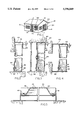
- FIG. 2 is a transverse sectional view of a typical installation directly wall mounted taken along section 2--2 of FIG. 7;
- FIG. 3 is a transverse sectional view of a typical system ceiling mounted taken along section 3--3 of FIG. 7;
- FIG. 4 is a transverse sectional view showing the same in a typical build-out or extended condition taken along 4--4 of FIG. 7;
- FIG. 5 is an end cap build-out condition taken at 5--5 of FIG. 7;
- FIG. 6A is a further removable sill application and sill in broken form
- FIG. 6B shows a floor mount
- FIG. 7 is a plan view of a typical panel system
- FIG. 8 is a transverse sectional view of a typical panel
- FIG. 9 is an exploded perspective partially broken view of the shutter system illustrative of the present invention.
- FIG. 10 is an enlarged perspective broken view concentrating on the lap joint and jack screw attachment portion of the system
- FIG. 11 is a view comparable to FIG. 7, but illustrating the alternative direct mount embodiment which omits headers, footers, and is secured directly at both the top and the bottom by an overlap;
- FIG. 12 is a view similar to FIG. 9, but illustrating the direct mount with the omission of the footer and the header;
- FIG. 13 is a vertical section taken along 13--13 of FIG. 11.
- FIG. 1 A typical installation of the subject shutter systems in several applications is shown in FIG. 1.
- the house 10 has a plurality of walls 11, and windows 12.
- a door 14 is centrally disposed in the front wall of the building 10, and a sliding door 16 at a sidewall portion of the building 10.
- the shutter system 20 as installed, in broad outline, will be best illustrated by reference to FIG. 7. There it will be seen that a plurality of shutter panels 30 have been joined together in a typical slide door 16 type installation.
- the sliding door shutter system 24 is noted in FIG. 1 where it will also be noted that there is a door shutter system 21 and a window shutter system 22.
- the illustrative shutter panel 30 includes a plurality of isosceles trapezoidal corrugations 31, including a ridge 32, and a groove portion 34. Ribs 35 are provided, as shown here, two on the ridge 32 and one centrally disposed on the bottom of the groove 34.
- the lateral lip 36 has a lip bottom 38 and a lip edge lock 40.
- a keyhole opening 41 is provided in the lip bottom 38 at the lower extremity of the panel 30.
- the upper portion of the panel 30 mounts in a header 60 which may take various configurations as will be shown in the description of FIGS. 2, 3 and 4.
- the panel lock assembly 45 includes a jack nut 46 which is secured to the lip channel 38 of the lip 36.
- a thumb screw 48 penetrates the lip bottom 38, passes through jack nut washer 49, and is threadedly engaged in the jack nut 46 by merely rotating with the thumb and forefinger.
- FIGS. 2, 3, and 4 Various foot constructions 56 and header construction 60 are shown in FIGS. 2, 3, and 4.
- the foot 55 has a bottom 56 which is secured to a concrete or masonry or other type of sill at the lower portion of the bottom 56 of the foot 55.
- the shutter face 58 is engaged by the wing nut 42.
- the header 60 includes a wall mount portion 61 and the header mount 62.
- the header 60 is mounted by a typical masonry engaging support.
- the header 60 has a grip portion 65 to engage the panel 30 upper portion.
- the extended mount 64 is shown in FIG. 4 where the entire shutter assembly system 20 is extended from the wall of the building structure.
- FIGS. 6A and 6B show illustrative floor mounts, FIG. 6A flush to the front portion of the floor, and FIG. 6B flush with the upper portion of the floor system.
- the panel 30 of FIG. 8 is nominally twelve inches from suspension point to suspension point. There is an overhang on either side to provide a lip engaging portion for the adjacent panel 30. Normally the height of the two corrugations 31 is two inches, the groove 34 is two inches, and the spacing of the top portion are 4.5 inches.
- a 0.063 thick aluminum 5052-H32 alloy is employed.
- a pair of spaced longitudinal ribs 35 are provided on the upper portion of the corrugation 31, with a single longitudinal rib 35 on the lower groove portion 34.
- the header 60 is provided with spacing of 2.15 inches at the narrowest portion to snugly receive each of the panels 30 as it is slipped upwardly into the header 60, and then lowered onto the footer.
- Each of the panels is provided with one or more jack nuts 46 which has its female portion securely mounted to the lip 36 of the underlying lip bottom 30 on the panel 30, and in spaced relationship longitudinally along the joint.
- a thumb screw 48 is provided to secure from the overlapping adjacent panel through the underlying fixed jack nut 46.
- a keyhole slot 41 is provided in both sides so that a bolt secured from the rear portion of the L-shaped receiver can be mounted as a hanger.
- a keyhole slot is provided in which the dimensions of the slot are at least 25% to 50% larger than the diameter of the bolt.
- the round portion of the keyhole slot is significantly larger.
- the shutter panels 30 may be directly mounted to the wall 11. This is illustrated in FIGS. 11 and 12. There it will be seen that the header 60 and the footer 55 are omitted from the construction. In order to directly mount, however, the center spacing of the top and bottom wing nuts 42 through the keyhole mounting portion 41 is important. If the mounts are on twelve inch centers, the shutter panel must overlie the opening at the top as well as at the bottom by at least four inches. On the other hand, if the shutter panel is only six inches wide, the subject overlap is two inches passed the opening both top and bottom. The same dimension applies to the lateral edges.
- the screw 70 When the direct mount is used the screw 70 is left in the wall with the screw head extending outwardly.
- the screw head imay be of an overall diameter or diagonal dimension small enough to fit through the large hole portion of the keyhole 41, whereas the shank 71 of the screw 70 with threads 72 is proportioned to snugly fit the slot portion of the keyhole.
- the panel mounting assembly 45 on the lateral lips 36 of the shutter panel 30 for securement of the adjacent shutters each to the other in spaced relationship running from the top to the bottom of the overlapped lateral legs 36. That remains the same as with the preferred embodiment set forth above. Similarly the securement over the walls of the opening must be on the same spacing.
- the spacing 75 from the opening to the screw 70 is sufficient to inhibit the development of a compression zone behind the monolithic shutter system.
- the spacing 75 should be four inches for a twelve inch panel and two inches for a six inch panel.
- the shutters are ideally secured by anchors 70 in concrete which are one-quarter inch tapcons, one and three-quarter inch imbedded or equivalent.
- anchors 70 In concrete which are one-quarter inch tapcons, one and three-quarter inch imbedded or equivalent.
- Rawl Caulk-In anchors which are one-quarter inch by seven-eighths inch imbedded or equivalent.
- All bolts, nuts, and washers are ideally stainless steel or aluminum alloy 2024-T4 or 7075-T6 or plated steel.
- the ideal ceiling header 60 has a foot portion 0.062 inches thick, with the bridge and overlap 0.100 inches. The same is proportioned so that the foot extends at least one-half inch beyond the shadow of the overlapping securing top member to permit easy access for drilling to secure the same to a wall.
- the panels 30 are ideally 0.063 aluminum alloy 5052-832 or ASTMB209-92A. They have a nominal width of twelve inches, with a total width of 13.5 inches, forming 2.00 inch deep ribs. The minimum separation to existing glass which i to be protected is 2.55 inches. The maximum clearance between the top of the panel and the inside of the header is one-quarter inches. As to special requirements, a one-quarter inch by one-half inch thumb screw 48 with washer 49 goes into the jack nut 46. They are spaced at twenty-four inch centers longitudinally along the joint, and are used to join all panels at the lap joints. Steel can also be used for the subject panels.
- the thickness should exceed 0.035 inches and sustain an ultimate load of at least 1064; a yield load of at least 862; an ultimate strength in psi of at least 55,150, and a yield stres psi of at least 44,675.
- the elongation should be at least 27.5% or less, the "E" factor 30 ⁇ 10 to the sixth power, Webster hardness 17, and Rockwell hardness 67.
- the aforesaid should conform to ASTM A525 for tolerances, and ASTM A446-93.
- the surface treatment is hot dip zinc coated with mill edge to a thickness of at least 0.035 inches.
- top track wall mount header 60 at the head, which is anchored to the wall, and fastened to the 2" ⁇ 2" ⁇ 0.125" (floor angle) continuous studded aluminum angle at the sill, using 1/4"-20 studs with washer wing nut spaced at 12" o.c.
- the panels are secured inside a top track (ceiling mount header) at the head, which is anchored to the inside of opening, and fastened to the 2" ⁇ 2" ⁇ 0.125" (floor angle) continuous studded aluminum angle at the sill, using 1/4"-20 studs with washer wing nut spaced at 12" o.c.
- Anchorage of the aluminum angles shall be to concrete, masonry and/or wood framing and shall consist of only the anchors. Permanent set fastener components, embedded anchor bolts, threaded cones or metal shields, not in use, must be protected against corrosion, contamination and damage at all time.
- the method of the present invention is directed to the installation of overlapping shutters in which the same are secured to the building structure by keyhole slots at the lower portion, and a keyhole slot at the upper portion in the event a header is not employed.
- the installer positions the units over the keyhole slots and into the upper portion first, and then thereafter takes the thumbscrews and manually secures them into the jack nuts which are securely fixed to the underneath portion of the overlapped portion of the adjacent panel.
- the method of mounting the direct mount implies that the installer will start at one lateral edge or the other of the opening. Each panel is hung over two screws 70 at the top, and then positioned over the two screws at the bottom.
Abstract
Description
Claims (6)
Priority Applications (2)
| Application Number | Priority Date | Filing Date | Title |
|---|---|---|---|
| US08/541,393 US5596849A (en) | 1994-11-23 | 1995-10-10 | Shutter system and method |
| US09/292,255 US6345476B1 (en) | 1994-11-23 | 1999-04-15 | Perforated pleated shutter and method |
Applications Claiming Priority (2)
| Application Number | Priority Date | Filing Date | Title |
|---|---|---|---|
| US08/344,222 US5487244A (en) | 1994-11-23 | 1994-11-23 | Shutter system and method |
| US08/541,393 US5596849A (en) | 1994-11-23 | 1995-10-10 | Shutter system and method |
Related Parent Applications (1)
| Application Number | Title | Priority Date | Filing Date |
|---|---|---|---|
| US08/344,222 Continuation-In-Part US5487244A (en) | 1994-11-23 | 1994-11-23 | Shutter system and method |
Related Child Applications (1)
| Application Number | Title | Priority Date | Filing Date |
|---|---|---|---|
| US72389396A Continuation-In-Part | 1994-11-23 | 1996-10-01 |
Publications (1)
| Publication Number | Publication Date |
|---|---|
| US5596849A true US5596849A (en) | 1997-01-28 |
Family
ID=23349571
Family Applications (2)
| Application Number | Title | Priority Date | Filing Date |
|---|---|---|---|
| US08/344,222 Expired - Lifetime US5487244A (en) | 1994-11-23 | 1994-11-23 | Shutter system and method |
| US08/541,393 Expired - Lifetime US5596849A (en) | 1994-11-23 | 1995-10-10 | Shutter system and method |
Family Applications Before (1)
| Application Number | Title | Priority Date | Filing Date |
|---|---|---|---|
| US08/344,222 Expired - Lifetime US5487244A (en) | 1994-11-23 | 1994-11-23 | Shutter system and method |
Country Status (2)
| Country | Link |
|---|---|
| US (2) | US5487244A (en) |
| CA (1) | CA2163141A1 (en) |
Cited By (24)
| Publication number | Priority date | Publication date | Assignee | Title |
|---|---|---|---|---|
| US5855099A (en) * | 1997-03-14 | 1999-01-05 | Hoffman; Robert E. | Sectional storm panel assembly |
| US6209263B1 (en) * | 2000-01-21 | 2001-04-03 | Ronald R. Poirier | Hurricane shutter system |
| US6263625B1 (en) | 1999-04-26 | 2001-07-24 | Lapointe Ray A. | Storm panel attachment system |
| US6345476B1 (en) | 1994-11-23 | 2002-02-12 | George A. Hill | Perforated pleated shutter and method |
| US6532702B1 (en) * | 2000-03-21 | 2003-03-18 | Paul J. Scribner | Building fixture protection apparatus having protective panels and a plurality of quick connect/disconnect means |
| WO2004009940A1 (en) | 2002-07-18 | 2004-01-29 | Weather Guard Hurricane Protection, Inc. | Integral frame system for windows and doors |
| US6708457B1 (en) | 2001-12-05 | 2004-03-23 | William E. Ballough | Concealed retaining channel for storm shutter attachment |
| US6745522B2 (en) * | 2001-06-27 | 2004-06-08 | Craig D. Germain | Telescoping hurricane shutters |
| US20050108974A1 (en) * | 2003-11-21 | 2005-05-26 | Richard Lauch | Escalator solid side truss construction |
| US20050210749A1 (en) * | 2004-03-24 | 2005-09-29 | Dubose Monty C | Gear shaft assembly |
| US6968660B1 (en) | 2002-11-18 | 2005-11-29 | Pablo Raba Novoa | Shutter assembly |
| US20050262789A1 (en) * | 2002-03-14 | 2005-12-01 | Novoa Pablo R | Modular construction assembly |
| US6978579B1 (en) * | 2003-09-11 | 2005-12-27 | Leonard Patrick Trinca | Storm shutter system |
| US20050284026A1 (en) * | 2004-06-25 | 2005-12-29 | Dubose Monty C | Shutter drive and lock assembly |
| US20060123717A1 (en) * | 2004-11-30 | 2006-06-15 | Huminski Glenn L | Hurricane Hanger |
| US20060185271A1 (en) * | 2005-02-22 | 2006-08-24 | Kurt Christensen | Severe weather protection system |
| US20090049772A1 (en) * | 2007-08-24 | 2009-02-26 | Shawn Milliken | Storm panel apparatus |
| US7584579B1 (en) | 2006-12-29 | 2009-09-08 | Thomas Joseph Everitt | Storm panel attachment system of plastic composition |
| US20100064606A1 (en) * | 2008-09-18 | 2010-03-18 | Devalapura Ravi K | Storm Shutter System |
| US8176963B1 (en) | 2007-04-18 | 2012-05-15 | Motosko Stephen J | Storm shutter panel and system with light openings |
| US8528279B1 (en) * | 2011-03-30 | 2013-09-10 | James Irvine Greene, JR. | Security grille and frame |
| US8590225B1 (en) * | 2008-02-29 | 2013-11-26 | Hurricane Safety Systems, Llc | System and method for attaching and quick releasing a first object to and from a second object |
| US9169672B1 (en) * | 2010-01-19 | 2015-10-27 | Nikolai Kislov | Hurricane protective system |
| US10094106B1 (en) | 2008-11-10 | 2018-10-09 | Hurricane Safety Systems Llc | Quick release system and method |
Families Citing this family (26)
| Publication number | Priority date | Publication date | Assignee | Title |
|---|---|---|---|---|
| US5768833A (en) * | 1994-06-15 | 1998-06-23 | Golen; Selig | Storm shutter retainer assembly |
| US5996292A (en) * | 1996-10-01 | 1999-12-07 | George Anthony Hill | Perforated shutter system and method |
| US5579615A (en) * | 1995-11-20 | 1996-12-03 | Hoffman; Robert E. | Sectional storm panel |
| US6205713B1 (en) * | 1996-02-06 | 2001-03-27 | Thomas Thompson | Hurricane/storm protection for windows/doors |
| US5755270A (en) * | 1996-11-05 | 1998-05-26 | Knezevich; Vladimir John | Accordion shutter system |
| US5927028A (en) * | 1997-06-25 | 1999-07-27 | Rossi; Jose E. | Double interlocking storm panel |
| US6021839A (en) * | 1998-09-17 | 2000-02-08 | Knezevich; Vladimir John | Accordion shutter system with improved header and sill configuration |
| US6189264B1 (en) * | 1999-07-30 | 2001-02-20 | Diveroli Oscar | Hurricane storm panel and method of installation |
| US6293059B1 (en) * | 2000-01-24 | 2001-09-25 | Robert F. Goodwin | Hurricane protective system for windows and doors |
| US6935082B2 (en) * | 2001-12-19 | 2005-08-30 | Paul D. Hemstreet | Storm impact protection system |
| CN1325745C (en) * | 2004-07-15 | 2007-07-11 | 李峰 | Concrete material reinforced stainless steel anti-theft net and its producing method |
| US20060010792A1 (en) * | 2004-07-19 | 2006-01-19 | Biggers Douglas W | Storm shutter apparatus |
| US7654044B2 (en) * | 2006-08-18 | 2010-02-02 | Allen Borland | Hurricane protection system |
| US7975440B2 (en) * | 2008-04-23 | 2011-07-12 | Motosko Stephen J | End cap for a corrugated hurricane shutter within an H-header |
| US7827744B2 (en) * | 2008-05-21 | 2010-11-09 | Clear Strength Usa Llc | Storm panel assembly for covering a window or door opening |
| CA2781763C (en) | 2009-10-27 | 2015-01-06 | Handy & Harman | Self-drilling bolt and nut assembly |
| US8726581B2 (en) * | 2011-09-15 | 2014-05-20 | SR Systems, LLC | Construction system providing structural integrity with integral seal |
| US8919050B2 (en) * | 2011-09-15 | 2014-12-30 | SR Systems, LLC | Anti-torsion construction system providing structural integrity and seismic resistance |
| CL2012002168U1 (en) * | 2012-08-03 | 2012-11-30 | Hunter Douglas Chile S A | Cladding for facades or walls, consisting of bent pressure panels, where the panels have a first and a second inclined tongue, with profiles at whose ends a first and a second inclined wing emerge, where said first second tongue fits perfectly with the profile that supports it. |
| JP6466779B2 (en) * | 2014-05-27 | 2019-02-06 | 住友林業株式会社 | Window crack protection device mounting structure |
| DE202014103897U1 (en) * | 2014-08-21 | 2014-09-04 | Richard Brink Gmbh & Co. Kg | pipe connectors |
| US20160145934A1 (en) * | 2014-11-05 | 2016-05-26 | Impact Security Llc | Protective Additional Glazing Systems, Apparatus, and Methods For Structural Openings |
| US10662699B2 (en) | 2015-03-06 | 2020-05-26 | Bobby R Soha | Rain shield for single and double hung windows |
| SE1500403A1 (en) * | 2015-10-07 | 2017-04-08 | Kullberg Sten-Magnus | Water barrier element |
| US10900219B1 (en) | 2018-04-24 | 2021-01-26 | Robert F. Goodwin | Hurricane protective systems for protruding openings |
| US10916927B2 (en) | 2019-03-22 | 2021-02-09 | J&C Group, Inc. | Bridge power module with high-joule in-wall surge protection |
Citations (3)
| Publication number | Priority date | Publication date | Assignee | Title |
|---|---|---|---|---|
| US4333271A (en) * | 1981-03-13 | 1982-06-08 | Nichols-Homeshield, Inc. | Hurricane panel security device |
| US5345716A (en) * | 1993-09-20 | 1994-09-13 | Caplan Mark A | Segmented multiple width storm shutter |
| US5426893A (en) * | 1994-05-26 | 1995-06-27 | Hoffman; Robert E. | Reinforced sectional storm panel |
-
1994
- 1994-11-23 US US08/344,222 patent/US5487244A/en not_active Expired - Lifetime
-
1995
- 1995-10-10 US US08/541,393 patent/US5596849A/en not_active Expired - Lifetime
- 1995-11-17 CA CA002163141A patent/CA2163141A1/en not_active Abandoned
Patent Citations (3)
| Publication number | Priority date | Publication date | Assignee | Title |
|---|---|---|---|---|
| US4333271A (en) * | 1981-03-13 | 1982-06-08 | Nichols-Homeshield, Inc. | Hurricane panel security device |
| US5345716A (en) * | 1993-09-20 | 1994-09-13 | Caplan Mark A | Segmented multiple width storm shutter |
| US5426893A (en) * | 1994-05-26 | 1995-06-27 | Hoffman; Robert E. | Reinforced sectional storm panel |
Cited By (28)
| Publication number | Priority date | Publication date | Assignee | Title |
|---|---|---|---|---|
| US6345476B1 (en) | 1994-11-23 | 2002-02-12 | George A. Hill | Perforated pleated shutter and method |
| US5855099A (en) * | 1997-03-14 | 1999-01-05 | Hoffman; Robert E. | Sectional storm panel assembly |
| US6263625B1 (en) | 1999-04-26 | 2001-07-24 | Lapointe Ray A. | Storm panel attachment system |
| US6209263B1 (en) * | 2000-01-21 | 2001-04-03 | Ronald R. Poirier | Hurricane shutter system |
| US6532702B1 (en) * | 2000-03-21 | 2003-03-18 | Paul J. Scribner | Building fixture protection apparatus having protective panels and a plurality of quick connect/disconnect means |
| US6745522B2 (en) * | 2001-06-27 | 2004-06-08 | Craig D. Germain | Telescoping hurricane shutters |
| US6708457B1 (en) | 2001-12-05 | 2004-03-23 | William E. Ballough | Concealed retaining channel for storm shutter attachment |
| US6820381B1 (en) | 2001-12-05 | 2004-11-23 | William E. Ballough | Concealed retaining channel for storm shutter attachment |
| US20050262789A1 (en) * | 2002-03-14 | 2005-12-01 | Novoa Pablo R | Modular construction assembly |
| WO2004009940A1 (en) | 2002-07-18 | 2004-01-29 | Weather Guard Hurricane Protection, Inc. | Integral frame system for windows and doors |
| US20050183379A1 (en) * | 2002-07-18 | 2005-08-25 | Sweeney John D. | Integral fame system for windows and doors |
| US6968660B1 (en) | 2002-11-18 | 2005-11-29 | Pablo Raba Novoa | Shutter assembly |
| US6978579B1 (en) * | 2003-09-11 | 2005-12-27 | Leonard Patrick Trinca | Storm shutter system |
| US20050108974A1 (en) * | 2003-11-21 | 2005-05-26 | Richard Lauch | Escalator solid side truss construction |
| US7040056B2 (en) | 2004-03-24 | 2006-05-09 | Dubose Monty C | Gear shaft assembly |
| US20050210749A1 (en) * | 2004-03-24 | 2005-09-29 | Dubose Monty C | Gear shaft assembly |
| US20050284026A1 (en) * | 2004-06-25 | 2005-12-29 | Dubose Monty C | Shutter drive and lock assembly |
| US20060123717A1 (en) * | 2004-11-30 | 2006-06-15 | Huminski Glenn L | Hurricane Hanger |
| US20060185271A1 (en) * | 2005-02-22 | 2006-08-24 | Kurt Christensen | Severe weather protection system |
| US7584579B1 (en) | 2006-12-29 | 2009-09-08 | Thomas Joseph Everitt | Storm panel attachment system of plastic composition |
| US8176963B1 (en) | 2007-04-18 | 2012-05-15 | Motosko Stephen J | Storm shutter panel and system with light openings |
| US20090049772A1 (en) * | 2007-08-24 | 2009-02-26 | Shawn Milliken | Storm panel apparatus |
| US7775001B2 (en) * | 2007-08-24 | 2010-08-17 | Shawn Milliken | Storm panel apparatus |
| US8590225B1 (en) * | 2008-02-29 | 2013-11-26 | Hurricane Safety Systems, Llc | System and method for attaching and quick releasing a first object to and from a second object |
| US20100064606A1 (en) * | 2008-09-18 | 2010-03-18 | Devalapura Ravi K | Storm Shutter System |
| US10094106B1 (en) | 2008-11-10 | 2018-10-09 | Hurricane Safety Systems Llc | Quick release system and method |
| US9169672B1 (en) * | 2010-01-19 | 2015-10-27 | Nikolai Kislov | Hurricane protective system |
| US8528279B1 (en) * | 2011-03-30 | 2013-09-10 | James Irvine Greene, JR. | Security grille and frame |
Also Published As
| Publication number | Publication date |
|---|---|
| US5487244A (en) | 1996-01-30 |
| CA2163141A1 (en) | 1996-05-24 |
Similar Documents
| Publication | Publication Date | Title |
|---|---|---|
| US5596849A (en) | Shutter system and method | |
| US20200165813A1 (en) | Universal mounting system | |
| US4074486A (en) | Panel wall construction | |
| US4041659A (en) | Metal building structure | |
| US3235039A (en) | Curtain wall support system | |
| US5881501A (en) | Roof system and panel therefor | |
| US3388514A (en) | Floor, wall and base plate connector | |
| IE64975B1 (en) | Conservatories | |
| CN111712605B (en) | Combined anchor and fastener assembly | |
| US3203151A (en) | Metal building construction | |
| US9062462B2 (en) | Trellis and accent band | |
| US8656681B1 (en) | Method for securing a panel over a gap in an exterior portion of a building | |
| US20040188039A1 (en) | Hurricane i-post | |
| JPH036737Y2 (en) | ||
| JPH0533609Y2 (en) | ||
| JPS5845375Y2 (en) | balcony beams | |
| WO1993019262A1 (en) | A building system | |
| JPS606493Y2 (en) | Roof or ceiling frame | |
| JPH0334431Y2 (en) | ||
| JP3031854B2 (en) | Dry fence | |
| JPS6029450Y2 (en) | protective fence | |
| JPH10238136A (en) | Earthquake-resistant reinforcing method of wooden house, etc. | |
| JPH0452329Y2 (en) | ||
| SU1188280A1 (en) | Roof panels to girder joint | |
| JPH052743Y2 (en) |
Legal Events
| Date | Code | Title | Description |
|---|---|---|---|
| STCF | Information on status: patent grant |
Free format text: PATENTED CASE |
|
| AS | Assignment |
Owner name: A.A.E. ACQUISITION CORPORATION, NEW YORK Free format text: ASSIGNMENT OF ASSIGNORS INTEREST;ASSIGNORS:HILL, GEORGE A., SR.;AMERICAN ALUMINUM ENTERPRISES, INC.;AMERICAN ALUMINUM ENTERPRISES OF NORTH FLORIDA, INC.;REEL/FRAME:010499/0266 Effective date: 19991031 Owner name: SAFEGUARD HURRICAN PROTECTION SYSTEMS, INC., NEW Y Free format text: ASSIGNMENT OF ASSIGNORS INTEREST;ASSIGNOR:A.A.E. ACQUISITION CORPORATION;REEL/FRAME:010499/0345 Effective date: 19991112 Owner name: A.A.E. ACQUISITION CORPORATION, NEW YORK Free format text: ASSIGNMENT OF ASSIGNORS INTEREST;ASSIGNORS:AMERICAN ALUMINUM ENTERPRISES, INC.;AMERICAN ALUMINUM ENTERPRISES FO NORTH FLORIDA, INC.;REEL/FRAME:010499/0354 Effective date: 19991101 |
|
| AS | Assignment |
Owner name: LASALLE BANK NATIONAL ASSOCIATION, FLORIDA Free format text: SECURITY INTEREST;ASSIGNOR:SAFEGUARD HURRICANE PROTECTION SYSTEMS, INC. F/K/A AAE ACQUISITON CORPORATION;REEL/FRAME:010881/0977 Effective date: 20000418 |
|
| FPAY | Fee payment |
Year of fee payment: 4 |
|
| AS | Assignment |
Owner name: WEATHERGUARD GUILDING PRODUCTS, INC., FLORIDA Free format text: ASSIGNMENT OF ASSIGNORS INTEREST;ASSIGNOR:SAFEGUARD HURRICANE PROTECTION SYSTEMS, INC.;REEL/FRAME:013578/0886 Effective date: 20020903 |
|
| FPAY | Fee payment |
Year of fee payment: 8 |
|
| FPAY | Fee payment |
Year of fee payment: 12 |
|
| AS | Assignment |
Owner name: AMERICAN METAL FABRICATORS, INC., FLORIDA Free format text: ASSIGNMENT OF ASSIGNORS INTEREST;ASSIGNOR:WEATHERGUARD BUILDING PRODUCTS, INC.;REEL/FRAME:027926/0038 Effective date: 20120315 |