US5627528A - Selective call receiver capable of suspending acknowledge-back signals and method therefor - Google Patents
Selective call receiver capable of suspending acknowledge-back signals and method therefor Download PDFInfo
- Publication number
- US5627528A US5627528A US08/395,254 US39525495A US5627528A US 5627528 A US5627528 A US 5627528A US 39525495 A US39525495 A US 39525495A US 5627528 A US5627528 A US 5627528A
- Authority
- US
- United States
- Prior art keywords
- acknowledge
- selective call
- receiver
- signal
- decoder
- Prior art date
- Legal status (The legal status is an assumption and is not a legal conclusion. Google has not performed a legal analysis and makes no representation as to the accuracy of the status listed.)
- Expired - Lifetime
Links
Images


Classifications
-
- H—ELECTRICITY
- H04—ELECTRIC COMMUNICATION TECHNIQUE
- H04W—WIRELESS COMMUNICATION NETWORKS
- H04W84/00—Network topologies
- H04W84/02—Hierarchically pre-organised networks, e.g. paging networks, cellular networks, WLAN [Wireless Local Area Network] or WLL [Wireless Local Loop]
- H04W84/022—One-way selective calling networks, e.g. wide area paging
- H04W84/025—One-way selective calling networks, e.g. wide area paging with acknowledge back capability
Definitions
- This invention relates in general to selective call systems, and in particular to a selective call receiver capable of suspending acknowledge-back responses.
- a message is delivered to the selective call receiver by transmitting the message during a predefined time period identifying the selective call receiver to which the message is intended.
- the selective call receiver as is well known, battery saves during the other time period until its predetermined time period occurs, during which, the selective call receiver turns-on and checks if a message is addressed to it. If not, the selective call receiver continue its battery save routine.
- the selective call systems have no way of telling if or when the message was received. Therefore, the selective call system can retransmit the same message for a predetermine number of times to ensure that the selective call receiver has every opportunity to receive the message. Unfortunately, the retransmission of messages waste valuable air-time.
- Acknowledge-back selective call receivers upon receipt of a message, are able to transmit an acknowledge-back response to the selective call system informing it that the message was received. Therefore, with acknowledge-back selective call receivers, the selective call system does not need to continue retransmitting the same message because the acknowledge back response verifies, among other things, that the message was received.
- the selective call receiver is portable and has a limited energy content battery, the transmission of the acknowledge back responses deplete the battery much quicker. As is well known, transmitting require more energy that receiving, therefore, the selective call receiver may receive pages but is unable to transmit the acknowledge-back responses because the battery is so depleted that it is unable to power-up the transmitter even thought the selective call receiver is still able to receive pages. Under these conditions, the selective call system may choose to continue retransmitting the same message although the message was received.
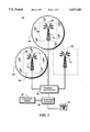
- FIG. 1 is an electrical block diagram of a selective call system in accordance with the preferred embodiment of the present invention.
- FIG. 2 is an electrical block diagram of a selective call base station in accordance with the preferred embodiment of the present invention.
- FIG. 3 is an electrical block diagram of a selective call receiver in accordance with the preferred embodiment of the present invention.
- FIG. 4 is an electrical block diagram of a microcomputer based decoder/controller suitable for use in the selective call receiver of FIG. 3.
- FIG. 5 illustrates an ack-back response in accordance with the preferred embodiment of the present invention.
- FIG. 6 is a flow diagram illustrating the operation of the selective call system in accordance with the preferred embodiment of the present invention.
- FIG. 7 is a flow diagram illustrating the operation of the selective call receiver in accordance with the preferred embodiment of the present invention.
- the selective call system 100 comprise a terminal/controller 104 coupled to a computer (not shown) via a modem 101 and a telephone 116 via a conventional public or private telephone network 102 known to one of ordinary skill in the art.
- the telephone network 102 through the base site terminal/controller 104 is coupled to a plurality of selective call base stations (or sites) 120-124.
- the plurality of selective call base stations 120-124 transmit and receive signals via its respective transmitters/receivers 110-114.
- the details of the operation of the selective call base stations 110-114 will be discussed below.
- the plurality of selective call base sites 120-124 have an associated coverage area (for example, 105 and 106) into which signals from the terminal/controller 104 are broadcast and received by at least one of a plurality of selective call receivers 108.
- the selective call base stations 120-124 comprise a telephone interconnect 201 which allows messages to enter into the selective call system 100 through a public or private telephone network using, for example, a telephone 116, a computer 102, or an alphanumeric entry device (not shown).
- a communication terminal 202 for example the Motorola's MODEN PLUS Encoder, processes the information received through the telephone interconnect 201.
- a generated address and message decoded from the received information are stored in a memory 204 until the next transmission cycle.
- the communication terminal 202 is coupled to a controller 206, which controls the operation of a link transmitter 208, a base site transmitter 210, a base site receiver 212, and a receiver 214.
- a controller suitable for use in the present invention is Motorola's MC6809 controller.
- a timing generator 216 coupled to the controller 206, provides a high accuracy clock to maintain system timing for communication and synchronization of the selective call system 100 including all the selective call base sites 120-124 and the plurality of selective call receiver 108 by techniques known to one skilled in the arts.
- the base site transmitter 210 transmits, to the plurality of selective call receivers 108, at least one of which has acknowledge-back capabilities, a signal which comprises a paging (selective call) type message preferably on a first frequency at the transmission cycle.
- a group of selective call receivers are intended (addressed) by the base site transmitter 210 to receive the paging message.
- the paging message before it is transmitted, is encoded with the appropriate address for addressing the group of selective call receivers of the plurality of selective call receivers 108.
- the selective call receivers of the group that received the message will substantially simultaneously transmit a response, the acknowledge back signals.
- the acknowledge back (acknowledgment or ack-back) response is transmitted on a second frequency preferably substantially lower than the first frequency.
- the receiver 214 of the selective call base sites 120-124 receives the acknowledge back response (ack signal or ack-back signal) which is stored in a memory 204. As is well known, the receiver 214 demodulates the ack-back signal to produce preferably a baseband signal.
- the baseband signal is converted (digitized) from an analog signal to a digital signal by an analog-to-digital (A/D) converter 220 known to one of ordinary skill in the art.
- the conversion by the A/D converter 220 are received and stored by a digital Signal Processor (DSP) 218.
- DSP digital Signal Processor
- the DSP 218 stores the digitized samples as digitized bits and continuously receives and stores the digitized samples until all bits of the ack-back signal have been received and stored. The digitized samples are retrieved and each bit decoded.
- the DSP determines whether the selective call receiver has transmitted a status indicator which indicates the suspension, deactivation or disabling the ack-back transmitter or that the selective call receiver is being turned-off or shut off.
- the DSP also has a timer 402 which is used as a delay circuit for delay the shutting down of the selective call receiver until the selective call system has acknowledges the ack back signal indicating that the selective call receiver 108 will be taken out of service.
- the operation of the DSP 218 will be discussed in detail below.
- the selective call receiver 108 comprises an antenna 302 for intercepting transmitted radio frequency (RF) signals which are coupled to the input of a receiver 304.
- the RF signals are preferably selective call (paging) message signals which provide, for example, a receiver address and an associated message, such as voice message.
- paging selective call
- the receiver 304 processes the RF signal and produces at the output a data stream representative of a demodulated data information.
- the FLEXTM signaling format Although other signaling formats could be utilized as well.
- the received address is compared with one or more addresses stored in a code plug (memory) 322, and when a match is detected, an alert signal is generated to alert a user that a selective call message, or page, has been received.
- the alert signal is directed to an audible alerting device 314 for generating an audible alert or to a tactile alerting device 316 for generating a silent vibrating alert.
- Switches 320 allow the user of the selective call receiver to, among other things, select between the audible alert 314 and the tactile alert 316 in a manner well known in the art.
- the decoder/controller 306 processes the message by encoding an addressed derived from the received message to generate the ack-back response.
- the encoded ack-back response is then transmitted to the selective call base station that originated the paging message by techniques well known to one of ordinary skill in the art.
- a power level of a battery (not shown) is checked by a level determinator to determine if the power supply is sufficient to transmit an ack-back signal in response to the message received.
- the decoder/controller 306 sets a status indicator which indicates that no ack back signal will be transmitted to the selective call system and the power switch 310 is used to deactivate or disconnect power to the ack back transmitter 334.
- the switches 320 are used to turn-off the selective call receiver 108
- the ack-back transmitter 334 sets the status indicator and transmit an ack-back signal informing the selective call system that it is being turned off. In this way, the selective call system will not need to waste air time re-transmitting the same message because it will know when the selective call receiver 108 is out of service or when the battery is too discharged to transmit ack-back response.
- a timer/counter 402 couples to the oscillator 418 and provides programmable timing functions which are utilized in controlling the operation of the receiver or the processor.
- a RAM (random access memory) 404 is utilized to store variables derived during processing, as well as to provide storage of message information which are received during operation as a selective call receiver.
- a ROM (read only memory) 406 stores the subroutines which control the operation of the receiver or the processor which will be discussed further. It will be appreciated that in many microcomputer implementations, the programmable-ROM (PROM) memory area can be provided either by a programmable read only memory (PROM) or an EEPROM (electrically erasable programmable read only memory).
- the oscillator 418, timer/counter 402, RAM 404, and ROM 406 are coupled through an address/data/control bus 408 to a central processing unit (CPU) 410 which performs the instructions and controls the operations of the microcomputer 306.
- CPU central processing unit
- the demodulated data generated by the receiver is coupled into the microcomputer 306 through an input/output (I/O) port 412.
- the demodulated data is processed by the CPU 410, and when the received address is the same as stored within the code-plug memory which couples into the microcomputer through, for example an I/O port 413, the message, if any, is received and stored in RAM 404.
- Recovery of the stored message, and selection of the predetermined destination address, is provided by the switches which are coupled to the I/O port 412.
- the microcomputer 306 then recovers the stored message and directs the information over the data bus 408 to the display driver 414 which processes the information and formats the information for presentation by a display 308 (FIG. 3) such as an LCD (liquid crystal display).
- the alert signal is generated which can be routed through the data bus 408 to an alert generator 416 that generates the alert enable signal which is coupled to the audible alert device that was described above.
- the microcomputer when the vibrator alert is selected, as described above, the microcomputer generates an alert enable signal which is coupled through data bus 408 to the I/O port 412 to enable generation of a vibratory, or silent alert.
- Switch inputs are received by the I/O port 412 via the data bus 408. The switch inputs are processed by the CPU 410.
- the CPU 410 retrieves the address of the selective call base station from RAM 404 and in conjunction with the timer counter 402 and the oscillator 418, the CPU 410 generates the ack-back signal which is passed via the data bus 408 to the transmitter.
- the selective call system comprises a plurality of base sites (or base stations) capable of communicating with at least one of a plurality of selective call receiver having acknowledge back (ack or ack-back) capabilities.
- the selective call receivers via its ack-back transmitters can send a signal to a base site to register with the selective call systems.
- the selective call systems determine if the selective call receiver requesting registration is assigned to the selective call system, step 602. If the selective call receiver is assigned to the selective call system, the selective call receiver will recognize the registration by logging or storing the registration information, step 604.
- the message When a message designated for a particular selective call receiver or group of selective call receivers, the message is encoded and sent to the selective call receiver or group of selective call receiver targeted at the base site(s) where the selective call receiver(s) is (are) located, step 608.
- the selective call system may send a "where-are-you" signal to the selective call receiver.
- the base site that received the ack-back signal of the responding selective call receiver marks (specifies) the location of the selective call receiver.
- the selective call system thereafter will target further communication with the selective call receiver at the base site of the location identified by the response to the "where-are-you" signal.
- step 610 the selective call system waits for the ack-back response or signal, step 612.
- Step 614 checks if the ack-back signal is received. If not, a time-out period is checked, step 616. If the time-out period has expired, the page may be re-sent to the pager to ensure that it was received, step 608. Alternatively, when the time-out period has not expired, step 614, the selective call system continues to wait until the ack-back signal is received or the time-out period has expired, step 612. At step 614, After, for example, the ack-back signal is received, the selective call receiver checks if an "out of service" signal had been received, step 618.
- the "out of service" signal indicates that the selective call receiver has been turned-off or shut down. If yes, the selective call system de-registers the selective call receiver from the active list of selective call receiver, step 620. If no, the selective call system checks if the ack suspension signal has been received (if ack-back responses disabled). If disabled, the selective call system updates the data base to indicate that when a selective call receiver or page is sent to that selective call receiver no ack back signal or response will be received, step 624. If the ack back suspension signal was not received or after the selective call system updates the data base to indicate no additional ack will be received, the selective call system indicates that the selective call message sent has been received, step 626.
- a selective call system can determine and store the location of the selective call receiver(s) assigned to the system. The stored location is retrieved to determine the geographic area in which to send the message to a designated selective call receiver instead of simulcasting the information over the entire selective call (paging) network thereby saving airtime.
- the ack-back selective call receivers are capable of informing the selective call system when they are being turned-off and when the battery condition is discharged below a power level sufficient to send ack back responses. This information when received by the selective call system is stored and use to determine when the selective call system is not to expect an ack back signal from the selective call receiver(s) in response to the message sent to the selective call receiver.
- step 704 when the selective call receiver is turned-up (powered-up) and the initialization of the selective call receiver is complete, step 704, the selective call receiver transmits an acknowledge-back signal to the selective call system to inform the system of its location and the it is active and ready to receive message, step 704.
- the selective call receiver checks its status, for example the power level of its battery or power supply to determine if the battery has sufficient energy available to transmit an ack back signal in response to a received message, step 706. If a status indicator 504 is set, the selective call receiver checks if the status indicator 504 relates to a low condition battery, 708.
- the selective call receiver transmits an ack back signal to the selective call system to inform it that no ack back signal will be sent in response to the receipt of the message, step 710.
- the selective receiver may also include information to inform the selective call system the condition that prevents further ack back signals, for example, low battery or the selective call receiver is being switched-off or shut-down.
- the selective call receiver initiate an "out of service" routine or sequence, step 712. "Out of service" routine include events or things that are performed before the selective call receiver allows the battery or the power supply to be disconnected.
- the selective call receiver transmits an "out of service" message to the selective call system which in turn removes the selective call receiver from the active system list to prevent messages being transmitted to the selective call receiver while it is out of service or turned-off.
- the selective call system responses to the ack-back signal, step 716.
- the selective call receiver shuts down, step 718. If the response from the selective call system is not received, the selective call system will retransmit the response from the selective call receiver, step 714.
- the selective call receiver begins searching for address, step 720. If no address is received, the selective call receiver continues by checking the status indicator 504, step 706. When the address is received, the selective call receiver begins decoding the received address, step 722. After the address is decoded, the selective call receiver according to the preferred embodiment begins to search or monitor the location being identified for the message, step 724. Step 726 checks when the message is received. If the message is not received, the process returns to step 726 of monitor the location for the message. Alternatively, when the message is received, the selective call receiver checks the low battery condition, step 728. If the low battery condition is set then the ack back transmitter will be disabled thereby suspending the transmission of ack-back responses, step 730. However, when the low battery condition is not set the ack back signal is transmitted to the selective call system in response to the receipt of the message, step 732.
- the pager when the pager is turned-on or signs-in, it registers with the selective call system by sending an acknowledge signal identifying the selective call receiver.
- the selective call receiver certifies the selective call receiver by checking to insure that the identification signal refers to valid selective call receiver (selective call receiver assigned to the selective call system.
- the ack signal from the selective call receiver to the selective call system identifies a valid selective call receiver and also serves to determine the location of the selective call receiver.
- the receiving base station transfers the ack signal with encoded portion (a color code included with the signal) to identify which base station (receiver/transmitter) received the radio frequency (RF) signal from the selective call receiver.
- the color code is used by the selective call system to target messages to the selective call receiver thereby eliminating the need for simulcasting which wastes air-time. Therefore, when a message (page) is transmitted to a selective call receiver with acknowledge back capabilities, the selective call receiver will transmit a ack-back signal in respond to the receipt of the message unless its battery supply is discharges below a minimum threshold thus preventing the selective call receiver from sending the ack-back signal.
- the selective call receiver will transmit an ack-signal to the selective call receiver informing the selective call system that no ack back signal will be sent in response to a message.
- the selective call system does not need to resend the message a preset number of times because no ack back signal was received because the selective call system knows that the selective call receiver is on but incapable of sending ack-back signals.
- a selective call receiver may have registered with the system thereby allowing the system to locate the position of the selective call receiver, the selective call receiver can migrate within in the system.
- the selective call system will periodically or occasionally send a simulcast signal ("where you are" signal or "Where U R" signal) requiring the selective call receiver to respond by transmitting ack back signal.
- the selective call system can determine during non-peak times or other various conditions or times for the selective call receiver to send ack-back signal so the selective call receiver can be located.
- the selective call receiver battery or power supply may become discharged to a level where it is preferred to disable or suspend the ack-back signal capability until the battery is replaced of recharged.
- the selective call receiver will send an ack signal to the selective call system informing the system of this condition so when a message is transmitted to the selective call receiver the system knows that the message is received and no ack-back signal will be sent in response thereto.
- the selective call receiver when the selective call receiver is being turned-off, it transmits an ack signal deregistering from the active system file so the selective call systems does not send and future message until the selective call receiver re-registers with the system. In this way, air-time is conserved, because the selective call receiver is able to keep the selective call system informed on its current status and when it is being taken out of service to eliminate unnecessary message being sent.
Abstract
Description
Claims (28)
Priority Applications (1)
| Application Number | Priority Date | Filing Date | Title |
|---|---|---|---|
| US08/395,254 US5627528A (en) | 1995-02-28 | 1995-02-28 | Selective call receiver capable of suspending acknowledge-back signals and method therefor |
Applications Claiming Priority (1)
| Application Number | Priority Date | Filing Date | Title |
|---|---|---|---|
| US08/395,254 US5627528A (en) | 1995-02-28 | 1995-02-28 | Selective call receiver capable of suspending acknowledge-back signals and method therefor |
Publications (1)
| Publication Number | Publication Date |
|---|---|
| US5627528A true US5627528A (en) | 1997-05-06 |
Family
ID=23562289
Family Applications (1)
| Application Number | Title | Priority Date | Filing Date |
|---|---|---|---|
| US08/395,254 Expired - Lifetime US5627528A (en) | 1995-02-28 | 1995-02-28 | Selective call receiver capable of suspending acknowledge-back signals and method therefor |
Country Status (1)
| Country | Link |
|---|---|
| US (1) | US5627528A (en) |
Cited By (24)
| Publication number | Priority date | Publication date | Assignee | Title |
|---|---|---|---|---|
| US5724410A (en) * | 1995-12-18 | 1998-03-03 | Sony Corporation | Two-way voice messaging terminal having a speech to text converter |
| EP0833528A2 (en) * | 1996-09-27 | 1998-04-01 | Nec Corporation | Two-way radio paging system having base station and mobile station implementing two-way communication of transmission reception |
| US5740540A (en) * | 1995-11-06 | 1998-04-14 | Mototola, Inc. | Method for telephone number notification and storage in a portable radio |
| US5870685A (en) * | 1996-09-04 | 1999-02-09 | Ericsson Inc. | Mobile station operations management based on battery capacity |
| US5918175A (en) * | 1996-11-25 | 1999-06-29 | Motorola, Inc. | Method and apparatus for registering mobile user groups |
| US5926106A (en) * | 1997-05-12 | 1999-07-20 | Bc Creations, Inc. | Access control using serial discretely coded RF transmissions initiated by a single event |
| US5960327A (en) * | 1996-12-06 | 1999-09-28 | Motorola | Method for a transceiver to select a channel |
| US5968129A (en) * | 1994-06-08 | 1999-10-19 | Hughes Electronics Corporation | Method and apparatus for selectively retrieving information from a source computer using a terrestrial or satellite interface |
| US20020046264A1 (en) * | 1998-11-03 | 2002-04-18 | Dillon Douglas M. | Method and apparatus for selectively allocating and enforcing bandwidth usage requirements on network users |
| US20030060159A1 (en) * | 2000-03-29 | 2003-03-27 | Thore Brynielsson | Method and system for radio communication with mobile units |
| US6571111B1 (en) * | 1998-08-05 | 2003-05-27 | Compaq Computer Corporation | Method and apparatus for reducing battery power consumption of transceivers in a communications network using an external generated timing signal |
| US6701370B1 (en) | 1994-06-08 | 2004-03-02 | Hughes Electronics Corporation | Network system with TCP/IP protocol spoofing |
| US6832091B1 (en) * | 1999-03-24 | 2004-12-14 | Sony Corporation | Radio transmission method and radio transmission |
| US20050143144A1 (en) * | 2003-12-29 | 2005-06-30 | Samsung Electronics Co., Ltd. | Apparatus and method for alerting a user of increased battery power consumption in mobile terminal |
| US6934255B1 (en) | 1999-02-02 | 2005-08-23 | Packeteer, Inc. | Internet over satellite apparatus |
| US20050192018A1 (en) * | 2001-08-14 | 2005-09-01 | Kyung-Hun Jang | Wireless data communication apparatus and method capable of checking receipt and status |
| US20050231378A1 (en) * | 2003-06-26 | 2005-10-20 | Oliver Young | Vehicle occupant sensing system having a low profile sensor assembly |
| US20060043716A1 (en) * | 2004-08-31 | 2006-03-02 | Quioc Eduardo L | Gas generating system |
| US20070083305A1 (en) * | 2005-10-11 | 2007-04-12 | Denso Corporation | Vehicle abnormality monitoring apparatus |
| US7343398B1 (en) | 2002-09-04 | 2008-03-11 | Packeteer, Inc. | Methods, apparatuses and systems for transparently intermediating network traffic over connection-based authentication protocols |
| US7733227B1 (en) * | 2006-01-19 | 2010-06-08 | Impinj, Inc. | RFID tags circuits and methods for sensing own power to predetermine feasibility of requested action |
| US20130235715A1 (en) * | 2001-01-26 | 2013-09-12 | Nec Corporation | Method and system for controlling communication network and router used in the network |
| US20180131768A1 (en) * | 2016-11-09 | 2018-05-10 | Hyundai Motor Company | Vehicle, server, telematics system including the same, and vehicle remote control method |
| US20210258874A1 (en) * | 2017-03-15 | 2021-08-19 | Avago Technologies International Sales Pte. Limited | Low power high definition wireless media transport |
Citations (12)
| Publication number | Priority date | Publication date | Assignee | Title |
|---|---|---|---|---|
| US4755816A (en) * | 1986-10-29 | 1988-07-05 | Motorola Inc. | Battery saving method for a selective call radio paging receiver |
| US4814763A (en) * | 1987-12-14 | 1989-03-21 | Motorola, Inc. | Paging terminal apparatus with page forwarding capability and methodology thereof |
| US4928096A (en) * | 1987-11-16 | 1990-05-22 | Motorola, Inc. | Paging terminal apparatus with message storage and retransmission capability and method therefor |
| US5031231A (en) * | 1988-09-26 | 1991-07-09 | Nec Corporation | Mobile telephone station with power saving circuit |
| US5047763A (en) * | 1989-11-30 | 1991-09-10 | Motorola, Inc. | Selective call system with message rebroadcasting over another selective call system |
| US5117449A (en) * | 1989-11-03 | 1992-05-26 | Motorola, Inc. | Dual receiver apparatus for integrated paging and radiotelephone functions |
| US5124697A (en) * | 1989-10-16 | 1992-06-23 | Motorola, Inc. | Acknowledge-back pager |
| US5142279A (en) * | 1989-06-05 | 1992-08-25 | Motorola, Inc. | Acknowledge back paging system having the capability of matching variable length data messages to pager addresses |
| US5148473A (en) * | 1991-08-30 | 1992-09-15 | Motorola, Inc. | Pager and radiotelephone apparatus |
| US5153582A (en) * | 1988-07-01 | 1992-10-06 | Motorola, Inc. | Method of and apparatus for acknowledging and answering a paging signal |
| US5438607A (en) * | 1992-11-25 | 1995-08-01 | U.S. Monitors, Ltd. | Programmable monitoring system and method |
| US5450612A (en) * | 1993-08-26 | 1995-09-12 | Motorola, Inc. | Communication system for communicating with a plurality of selective call receivers and method therefor |
-
1995
- 1995-02-28 US US08/395,254 patent/US5627528A/en not_active Expired - Lifetime
Patent Citations (12)
| Publication number | Priority date | Publication date | Assignee | Title |
|---|---|---|---|---|
| US4755816A (en) * | 1986-10-29 | 1988-07-05 | Motorola Inc. | Battery saving method for a selective call radio paging receiver |
| US4928096A (en) * | 1987-11-16 | 1990-05-22 | Motorola, Inc. | Paging terminal apparatus with message storage and retransmission capability and method therefor |
| US4814763A (en) * | 1987-12-14 | 1989-03-21 | Motorola, Inc. | Paging terminal apparatus with page forwarding capability and methodology thereof |
| US5153582A (en) * | 1988-07-01 | 1992-10-06 | Motorola, Inc. | Method of and apparatus for acknowledging and answering a paging signal |
| US5031231A (en) * | 1988-09-26 | 1991-07-09 | Nec Corporation | Mobile telephone station with power saving circuit |
| US5142279A (en) * | 1989-06-05 | 1992-08-25 | Motorola, Inc. | Acknowledge back paging system having the capability of matching variable length data messages to pager addresses |
| US5124697A (en) * | 1989-10-16 | 1992-06-23 | Motorola, Inc. | Acknowledge-back pager |
| US5117449A (en) * | 1989-11-03 | 1992-05-26 | Motorola, Inc. | Dual receiver apparatus for integrated paging and radiotelephone functions |
| US5047763A (en) * | 1989-11-30 | 1991-09-10 | Motorola, Inc. | Selective call system with message rebroadcasting over another selective call system |
| US5148473A (en) * | 1991-08-30 | 1992-09-15 | Motorola, Inc. | Pager and radiotelephone apparatus |
| US5438607A (en) * | 1992-11-25 | 1995-08-01 | U.S. Monitors, Ltd. | Programmable monitoring system and method |
| US5450612A (en) * | 1993-08-26 | 1995-09-12 | Motorola, Inc. | Communication system for communicating with a plurality of selective call receivers and method therefor |
Cited By (50)
| Publication number | Priority date | Publication date | Assignee | Title |
|---|---|---|---|---|
| US6839770B1 (en) | 1994-06-08 | 2005-01-04 | Hughes Electronics Corporation | Apparatus and method for access to network via satellite |
| US7325063B2 (en) | 1994-06-08 | 2008-01-29 | Hughes Electronics Corporation | Apparatus, method, and system for removing ethernet header and adding second IP header |
| US7774501B2 (en) | 1994-06-08 | 2010-08-10 | Hughes Network Systems, Llc | Network layer tunnel apparatus having transport layer/network layer stack and network layer tunnel and method using network layer tunnel |
| US7337233B2 (en) | 1994-06-08 | 2008-02-26 | Hughes Network Systems, Inc. | Network system with TCP/IP protocol spoofing |
| US6931512B2 (en) | 1994-06-08 | 2005-08-16 | Hughes Electronics Corporation | Method and apparatus for selectively retrieving information from a source computer using a terrestrial or satellite interface |
| US6338131B1 (en) | 1994-06-08 | 2002-01-08 | Hughes Electronics Corporation | Network system with TCP/IP ACK reduction |
| US20040202166A1 (en) * | 1994-06-08 | 2004-10-14 | Hughes Electronics Corporation | Network system with TCP/IP protocol spoofing |
| US5968129A (en) * | 1994-06-08 | 1999-10-19 | Hughes Electronics Corporation | Method and apparatus for selectively retrieving information from a source computer using a terrestrial or satellite interface |
| US5995726A (en) * | 1994-06-08 | 1999-11-30 | Hughes Electronics Corporation | Method and apparatus for requesting and retrieving information from a source computer using terrestrial and satellite interfaces |
| US5995725A (en) * | 1994-06-08 | 1999-11-30 | Hughes Electronics Corporation | Method and apparatus for requesting and retrieving information from a source computer using terrestrial and satellite interfaces |
| US20040088383A1 (en) * | 1994-06-08 | 2004-05-06 | Hughes Electronics Corporation | Apparatus and method for access to network via satellite |
| US6016388A (en) * | 1994-06-08 | 2000-01-18 | Hughes Electronics Corporation | Method and apparatus for requesting and retrieving information from a source computer using terrestrial and satellite interfaces |
| US6115750A (en) * | 1994-06-08 | 2000-09-05 | Hughes Electronics Corporation | Method and apparatus for selectively retrieving information from a source computer using a terrestrial or satellite interface |
| US6161141A (en) * | 1994-06-08 | 2000-12-12 | Hughes Electronics Corporation | Network system with TCP/IP protocol spoofing |
| US6321268B1 (en) | 1994-06-08 | 2001-11-20 | Hughes Electronics Corporation | Method and apparatus for selectively retrieving information from a source computer using a terrestrial or satellite interface |
| US20050053082A1 (en) * | 1994-06-08 | 2005-03-10 | Hughes Electronics Corporation | Apparatus and method for hybrid network access |
| US6701370B1 (en) | 1994-06-08 | 2004-03-02 | Hughes Electronics Corporation | Network system with TCP/IP protocol spoofing |
| US6519651B1 (en) | 1994-06-08 | 2003-02-11 | Hughes Electronics Corporation | Apparatus and method for hybrid network access |
| US6671741B1 (en) | 1994-06-08 | 2003-12-30 | Hughes Electronics Corp. | Apparatus and method for hybrid network access |
| US5740540A (en) * | 1995-11-06 | 1998-04-14 | Mototola, Inc. | Method for telephone number notification and storage in a portable radio |
| US5724410A (en) * | 1995-12-18 | 1998-03-03 | Sony Corporation | Two-way voice messaging terminal having a speech to text converter |
| US5870685A (en) * | 1996-09-04 | 1999-02-09 | Ericsson Inc. | Mobile station operations management based on battery capacity |
| EP0833528A3 (en) * | 1996-09-27 | 2000-01-12 | Nec Corporation | Two-way radio paging system having base station and mobile station implementing two-way communication of transmission reception |
| EP0833528A2 (en) * | 1996-09-27 | 1998-04-01 | Nec Corporation | Two-way radio paging system having base station and mobile station implementing two-way communication of transmission reception |
| US5918175A (en) * | 1996-11-25 | 1999-06-29 | Motorola, Inc. | Method and apparatus for registering mobile user groups |
| US5960327A (en) * | 1996-12-06 | 1999-09-28 | Motorola | Method for a transceiver to select a channel |
| US5926106A (en) * | 1997-05-12 | 1999-07-20 | Bc Creations, Inc. | Access control using serial discretely coded RF transmissions initiated by a single event |
| US6571111B1 (en) * | 1998-08-05 | 2003-05-27 | Compaq Computer Corporation | Method and apparatus for reducing battery power consumption of transceivers in a communications network using an external generated timing signal |
| US7562130B2 (en) | 1998-11-03 | 2009-07-14 | Hughes Network Systems, Inc. | Method and apparatus for selectively allocating and enforcing bandwidth usage requirements on network users |
| US20020046264A1 (en) * | 1998-11-03 | 2002-04-18 | Dillon Douglas M. | Method and apparatus for selectively allocating and enforcing bandwidth usage requirements on network users |
| US6934255B1 (en) | 1999-02-02 | 2005-08-23 | Packeteer, Inc. | Internet over satellite apparatus |
| US20050232180A1 (en) * | 1999-02-02 | 2005-10-20 | Toporek Jerome D | Internet over satellite apparatus |
| US6832091B1 (en) * | 1999-03-24 | 2004-12-14 | Sony Corporation | Radio transmission method and radio transmission |
| US20030060159A1 (en) * | 2000-03-29 | 2003-03-27 | Thore Brynielsson | Method and system for radio communication with mobile units |
| US7046958B2 (en) * | 2000-03-29 | 2006-05-16 | Ab Tryggit | Method and system for radio communication with mobile units |
| US9924411B2 (en) | 2001-01-26 | 2018-03-20 | Nec Corporation | Method and system for controlling communication network and router used in the network |
| US9301201B2 (en) * | 2001-01-26 | 2016-03-29 | Nec Corporation | Method and system for controlling communication network and router used in the network |
| US20130235715A1 (en) * | 2001-01-26 | 2013-09-12 | Nec Corporation | Method and system for controlling communication network and router used in the network |
| US20050192018A1 (en) * | 2001-08-14 | 2005-09-01 | Kyung-Hun Jang | Wireless data communication apparatus and method capable of checking receipt and status |
| US7343398B1 (en) | 2002-09-04 | 2008-03-11 | Packeteer, Inc. | Methods, apparatuses and systems for transparently intermediating network traffic over connection-based authentication protocols |
| US20050231378A1 (en) * | 2003-06-26 | 2005-10-20 | Oliver Young | Vehicle occupant sensing system having a low profile sensor assembly |
| US7251505B2 (en) * | 2003-12-29 | 2007-07-31 | Samsung Electronics Co., Ltd. | Apparatus and method for alerting a user of increased battery power consumption in mobile terminal |
| US20050143144A1 (en) * | 2003-12-29 | 2005-06-30 | Samsung Electronics Co., Ltd. | Apparatus and method for alerting a user of increased battery power consumption in mobile terminal |
| US20060043716A1 (en) * | 2004-08-31 | 2006-03-02 | Quioc Eduardo L | Gas generating system |
| US20070083305A1 (en) * | 2005-10-11 | 2007-04-12 | Denso Corporation | Vehicle abnormality monitoring apparatus |
| US7809481B2 (en) * | 2005-10-11 | 2010-10-05 | Denso Corporation | Vehicle abnormality monitoring apparatus |
| US7733227B1 (en) * | 2006-01-19 | 2010-06-08 | Impinj, Inc. | RFID tags circuits and methods for sensing own power to predetermine feasibility of requested action |
| US20180131768A1 (en) * | 2016-11-09 | 2018-05-10 | Hyundai Motor Company | Vehicle, server, telematics system including the same, and vehicle remote control method |
| US10771557B2 (en) * | 2016-11-09 | 2020-09-08 | Hyundai Motor Company | Vehicle, server, telematics system including the same, and vehicle remote control method |
| US20210258874A1 (en) * | 2017-03-15 | 2021-08-19 | Avago Technologies International Sales Pte. Limited | Low power high definition wireless media transport |
Similar Documents
| Publication | Publication Date | Title |
|---|---|---|
| US5627528A (en) | Selective call receiver capable of suspending acknowledge-back signals and method therefor | |
| EP0826283B1 (en) | Downloading location specific information to a selective call receiver | |
| US5381133A (en) | Selective call receiver with battery saving features and method therefor | |
| KR100273857B1 (en) | Method for determining available frequencies in selective call receivers | |
| US5382949A (en) | Method for increasing battery life for selective call receivers | |
| US6069929A (en) | Wireless communication system compulsively turning remote terminals into inactive state | |
| EP0321698B1 (en) | Paging system with acknowledgement | |
| JP2797713B2 (en) | Selective call receiver and method for requesting information from a communication system | |
| JP3950939B2 (en) | Method and apparatus for organizing and recovering information communicated in a wireless communication system | |
| JPH09503633A (en) | Method and apparatus for identifying a transmitter in a wireless communication system | |
| US5376929A (en) | Selective call receiver with battery saving features and method therefor | |
| KR950012825B1 (en) | Paging system employing designated frame commencing information service data message transmission | |
| AU675578B2 (en) | Communication system for communicating with a plurality of selective call receivers and method therefor | |
| KR100352564B1 (en) | Messaging system for conditionally selecting a network | |
| US6603389B1 (en) | Method for indicating a delinquent response to a message from a selective call device | |
| US5710972A (en) | Method and apparatus for deferring zone resistrations from a PSU-pager when the PSU's own call rate is less than or equal to a transmitted threshold | |
| US5850186A (en) | Method of receiving radio paging signal | |
| JP3202753B2 (en) | Method and apparatus for delivering global event information in a wireless communication system | |
| EP0963627B1 (en) | Selective call device and method for battery saving during information services | |
| US20020058508A1 (en) | Radio communication terminal for optimizing transmission of messages to selective call transceivers and method therefor | |
| EP0873610B1 (en) | Method and apparatus for providing roaming instructions to data communication receivers | |
| WO2001019064A1 (en) | Method for disclosing a password of a selective call device |
Legal Events
| Date | Code | Title | Description |
|---|---|---|---|
| AS | Assignment |
Owner name: MOTOROLA, INC., FLORIDA Free format text: ASSIGNMENT OF ASSIGNORS INTEREST;ASSIGNOR:KUZNICKI, WILLIAM JOSEPH;REEL/FRAME:007382/0125 Effective date: 19950228 |
|
| STCF | Information on status: patent grant |
Free format text: PATENTED CASE |
|
| CC | Certificate of correction | ||
| FPAY | Fee payment |
Year of fee payment: 4 |
|
| FPAY | Fee payment |
Year of fee payment: 8 |
|
| FPAY | Fee payment |
Year of fee payment: 12 |
|
| AS | Assignment |
Owner name: MOTOROLA MOBILITY, INC, ILLINOIS Free format text: ASSIGNMENT OF ASSIGNORS INTEREST;ASSIGNOR:MOTOROLA, INC;REEL/FRAME:025673/0558 Effective date: 20100731 |
|
| AS | Assignment |
Owner name: MOTOROLA MOBILITY LLC, ILLINOIS Free format text: CHANGE OF NAME;ASSIGNOR:MOTOROLA MOBILITY, INC.;REEL/FRAME:029216/0282 Effective date: 20120622 |
|
| AS | Assignment |
Owner name: GOOGLE TECHNOLOGY HOLDINGS LLC, CALIFORNIA Free format text: ASSIGNMENT OF ASSIGNORS INTEREST;ASSIGNOR:MOTOROLA MOBILITY LLC;REEL/FRAME:034487/0001 Effective date: 20141028 |