US5691754A - Rigid tube off-axis ink supply - Google Patents
Rigid tube off-axis ink supply Download PDFInfo
- Publication number
- US5691754A US5691754A US08/700,068 US70006896A US5691754A US 5691754 A US5691754 A US 5691754A US 70006896 A US70006896 A US 70006896A US 5691754 A US5691754 A US 5691754A
- Authority
- US
- United States
- Prior art keywords
- ink
- movable
- ink jet
- coupler
- rigid
- Prior art date
- Legal status (The legal status is an assumption and is not a legal conclusion. Google has not performed a legal analysis and makes no representation as to the accuracy of the status listed.)
- Expired - Lifetime
Links
Images

Classifications
-
- B—PERFORMING OPERATIONS; TRANSPORTING
- B41—PRINTING; LINING MACHINES; TYPEWRITERS; STAMPS
- B41J—TYPEWRITERS; SELECTIVE PRINTING MECHANISMS, i.e. MECHANISMS PRINTING OTHERWISE THAN FROM A FORME; CORRECTION OF TYPOGRAPHICAL ERRORS
- B41J2/00—Typewriters or selective printing mechanisms characterised by the printing or marking process for which they are designed
- B41J2/005—Typewriters or selective printing mechanisms characterised by the printing or marking process for which they are designed characterised by bringing liquid or particles selectively into contact with a printing material
- B41J2/01—Ink jet
- B41J2/17—Ink jet characterised by ink handling
- B41J2/175—Ink supply systems ; Circuit parts therefor
- B41J2/17503—Ink cartridges
- B41J2/17506—Refilling of the cartridge
- B41J2/17509—Whilst mounted in the printer
-
- B—PERFORMING OPERATIONS; TRANSPORTING
- B41—PRINTING; LINING MACHINES; TYPEWRITERS; STAMPS
- B41J—TYPEWRITERS; SELECTIVE PRINTING MECHANISMS, i.e. MECHANISMS PRINTING OTHERWISE THAN FROM A FORME; CORRECTION OF TYPOGRAPHICAL ERRORS
- B41J2/00—Typewriters or selective printing mechanisms characterised by the printing or marking process for which they are designed
- B41J2/005—Typewriters or selective printing mechanisms characterised by the printing or marking process for which they are designed characterised by bringing liquid or particles selectively into contact with a printing material
- B41J2/01—Ink jet
- B41J2/17—Ink jet characterised by ink handling
- B41J2/175—Ink supply systems ; Circuit parts therefor
-
- B—PERFORMING OPERATIONS; TRANSPORTING
- B41—PRINTING; LINING MACHINES; TYPEWRITERS; STAMPS
- B41J—TYPEWRITERS; SELECTIVE PRINTING MECHANISMS, i.e. MECHANISMS PRINTING OTHERWISE THAN FROM A FORME; CORRECTION OF TYPOGRAPHICAL ERRORS
- B41J29/00—Details of, or accessories for, typewriters or selective printing mechanisms not otherwise provided for
- B41J29/377—Cooling or ventilating arrangements
-
- B—PERFORMING OPERATIONS; TRANSPORTING
- B41—PRINTING; LINING MACHINES; TYPEWRITERS; STAMPS
- B41J—TYPEWRITERS; SELECTIVE PRINTING MECHANISMS, i.e. MECHANISMS PRINTING OTHERWISE THAN FROM A FORME; CORRECTION OF TYPOGRAPHICAL ERRORS
- B41J2/00—Typewriters or selective printing mechanisms characterised by the printing or marking process for which they are designed
- B41J2/005—Typewriters or selective printing mechanisms characterised by the printing or marking process for which they are designed characterised by bringing liquid or particles selectively into contact with a printing material
- B41J2/01—Ink jet
- B41J2/17—Ink jet characterised by ink handling
- B41J2/175—Ink supply systems ; Circuit parts therefor
- B41J2/17596—Ink pumps, ink valves
Definitions
- the disclosed invention is generally directed to off-axis ink supply systems for ink jet printers and plotters, and more particularly to an off-axis ink supply system that utilizes rigid ink supply tubes.
- Ink jet printers and plotters are well known, and typically include one or more printhead cartridges, each having an ink emitting ink jet printhead and an ink reservoir.
- the printhead cartridges are supported by a movable print carriage that is reciprocatingly scanned across print media which is advanced between scans of the print carriage.
- off-axis or off-line ink delivery systems have been designed wherein an off-axis ink supply is located remotely from the carriage and the printhead cartridge, and is coupled to the printhead cartridge reservoir by a flexible ink conveying tube that is typically made of plastic.
- an ink jet printer that includes a movable print carriage, an ink jet printhead cartridge removably supported by the movable print carriage, a stationary ink reservoir located remotely from the ink jet printhead cartridge, a movable ink conveying coupler fluidically coupled to the stationary ink reservoir, and a rigid ink conveying tube connected between the movable ink conveying coupler and the ink jet printhead cartridge, wherein the movable ink conveying coupler moves relative to the stationary ink reservoir as the movable carriage moves along a carriage axis.
- a further rigid ink conveying tube is connected between the printhead cartridge and the movable ink conveying coupler, and a pump is driven by the movement of the movable ink conveying coupler.
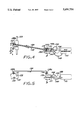
- FIG. 1 schematically sets forth a top plan view of an implementation of an ink jet printer that incorporates an off-axis ink delivery system in accordance with the invention.
- FIG. 2 schematically sets forth a side elevational view of the ink jet printer of FIG. 1.
- FIG. 3 schematically sets forth a top plan view of an implementation of an ink jet printer that incorporates an off-axis ink delivery system in accordance with the invention which includes a pump.
- FIG. 4 schematically sets forth a top plan view of an implementation of an ink jet printer that incorporates a further off-axis ink delivery system in accordance with the invention.
- FIG. 5 schematically sets forth a side elevational view of the ink jet printer of FIG. 4.
- FIGS. 1 and 2 schematically set forth therein are a top plan view and a side elevational view of an implementation of an ink jet printer that incorporates an off-axis ink delivery system in accordance with the invention.
- the ink jet printer off-axis ink delivery system broadly includes a movable print carriage 21 that is mounted on a guide rail 23 for reciprocating translational movement along a carriage scan axis A.
- a printhead cartridge 25 is removably retained on the print carriage 21.
- the printhead cartridge 25 includes a thermal ink jet printhead 26 that fires ink drops downwardly onto a print medium 28.
- a stationary remote ink reservoir 31 is located remotely from the printhead cartridges 25, and a movable ink conveying coupler 33 is fluidically coupled to the remote ink reservoir by a pipe 35 that is fixedly attached to the movable ink conveying coupler 33 and slidably engaged in a sliding seal 37 that is incorporated in the stationary ink reservoir 31.
- the movable ink conveying coupler is suitably supported for reciprocating linear movement along an axis B that is orthogonal to the carriage scan axis A, for example in a track or on a rail, and the pipe 35 and seal 37 are configured so that the translation of the pipe 35 is along the longitudinal axis thereof.
- a rigid ink conveying tube 38 is connected between the movable ink conveying coupler 33 and the printhead cartridge 25.
- the rigid ink conveying tube 38 includes a linear elongated section 38a, and short, parallel linear sections 38b, 38c connected at right angles to the linear elongated section by respective elbow sections.
- the short section 38b of the rigid tube 38 is rotatably engaged in a seal 41 disposed in the top of the printhead cartridge 25 for rotation about the longitudinal axis of the short section 38b.
- the other short section 38c of the rigid tube 38 is rotatably engaged in an associated seal 43 disposed in the top of the movable ink conveying coupler 33.
- the rigid ink conveying tube 38 comprises an aluminum alloy or stainless steel, for example.
- movable coupler 33 is illustrated as being fluidically coupled to the ink reservoir 31 by a pipe that slides in a seal 37, it should be appreciated that a flexible conduit can be utilized to accommodate the movement of the movable coupler 33.
- a pump 45 can be coupled between a rigid ink conveying tube 38 and a stationary remote ink reservoir 231.
- the rigid ink conveying tube 38 includes a short angled section, similarly to the short section 38c of the rigid tube 38 of FIGS. 1 and 2, that is rotatably disposed in the top of a movable coupler 233, for example in a suitable bushing.
- the output of the pump 45 is connected to a short angled section of the rigid ink conveying tube 38 by a conduit 48 which includes a flexible tube portion that accommodates the movement of the movable coupler 33, and a conduit 58 is connected between the input of the pump 45 and a stationary remote ink reservoir 231.
- the pump 45 is actuated by an actuating rod 51 that is connected between the movable coupler 33 and the pump 45, whereby the pump 45 is driven by the reciprocating motion of the movable coupler 33.
- the pump 45 can comprise an electrically actuated pump.
- FIGS. 4 and 5 schematically set forth therein are a top plan view and a side elevational view of another implementation of an off-axis continuous ink delivery system in accordance with the invention.
- the ink jet printer off-axis continuous ink delivery system broadly includes a movable print carriage 121 that is mounted on a guide rail 123 for reciprocating translational movement along a carriage scan axis.
- a printhead cartridge 125 is removably retained on the print carriage 121.
- a pair of parallel, equal length ink conveying tubes 138, 139 are connected between the printhead cartridge 125 and a movable coupler 133 that is suitably supported for reciprocating linear movement along an axis that is orthogonal to the carriage scan axis, for example in a track or on a rail.
- the rigid ink conveying tube 138 comprises an ink supply tube, for example, while the rigid ink conveying tube 139 comprises an ink return tube.
- Each of the rigid ink conveying tubes 138, 139 is substantially similar to the rigid ink tube 38 of the ink jet printer of FIGS. 1 and 2.
- Each of the rigid ink conveying tubes 138, 139 thus includes a linear elongated section and short parallel linear sections connected at right angles to the linear elongated section by respective elbow sections.
- the short sections 138b, 139b of the rigid tubes 138, 139 are rotatably engaged in a seal 141 disposed in the top of the printhead cartridge 125, while the short sections 138c, 139c of the rigid tubes 138, 139 are rotatably engaged in a bushing 143 in the top of the movable coupler 133.
- the rotational centers of the short sections 138b, 139b are collinear on a line that is parallel to the carriage axis A; the rotational centers of the short sections 138c, 139c are collinear on a line that is parallel to the carriage scan axis A; and the elongated sections of the rigid tubes 138, 139 are of substantially equal length.
- the short sections of the rigid tubes 138, 139 rotate at the vertexes of a parallelogram.
- the ink delivery tube 138 is fluidically connected to the output of a pump 145 by a conduit 148 which includes a flexible tube portion that accommodates the movement of the movable coupler 133.
- a conduit 158 is connected between the input of the pump 145 and a stationary remote ink reservoir 131 associated with the printhead cartridge 125.
- the stationary remote ink reservoir 131 is located remotely from the printhead cartridge 125.
- the pump 145 is actuated by an actuating rod 151 that is connected between the movable coupler 133 and the pump 145, whereby the pump is driven by the reciprocating motion of the movable coupler 133.
- the pump 145 can comprise an electrically actuated pump.
- the ink return tube 139 is fluidically connected to the stationary remote ink reservoir 131 by a conduit 149 which includes a flexible tube portion that accommodates the movement of the movable coupler 133.
- the reciprocating motion of the print carriage 121 causes the movable coupler 133 to move reciprocatingly, which in turn causes the pump 145 to pump ink to the printhead cartridge 125 via the ink output tube 138.
- the ink provided to the printhead 125 via the ink delivery tube 138 exceeds the amount of ink consumed by the printhead 125, and the excess ink is returned via the rigid ink return tube 139.
- the ink delivery system of FIGS. 3 and 4 is thus a recirculating system wherein ink is continually recirculated.
- components including the ink, the rigid ink tubes 138, 139, the movable coupler 133, the conduits 148, 149, and the remote stationary ink reservoir 131 function as a heat exchanger that cools the printhead 125 by transferring heat from the printhead to the ambient air.
Abstract
Description
Claims (6)
Priority Applications (1)
| Application Number | Priority Date | Filing Date | Title |
|---|---|---|---|
| US08/700,068 US5691754A (en) | 1996-08-19 | 1996-08-19 | Rigid tube off-axis ink supply |
Applications Claiming Priority (1)
| Application Number | Priority Date | Filing Date | Title |
|---|---|---|---|
| US08/700,068 US5691754A (en) | 1996-08-19 | 1996-08-19 | Rigid tube off-axis ink supply |
Publications (1)
| Publication Number | Publication Date |
|---|---|
| US5691754A true US5691754A (en) | 1997-11-25 |
Family
ID=24812061
Family Applications (1)
| Application Number | Title | Priority Date | Filing Date |
|---|---|---|---|
| US08/700,068 Expired - Lifetime US5691754A (en) | 1996-08-19 | 1996-08-19 | Rigid tube off-axis ink supply |
Country Status (1)
| Country | Link |
|---|---|
| US (1) | US5691754A (en) |
Cited By (16)
| Publication number | Priority date | Publication date | Assignee | Title |
|---|---|---|---|---|
| US6059401A (en) * | 1998-03-19 | 2000-05-09 | Hewlett-Packard Company | Alignment coupling device for manually connecting an ink supply to an inkjet print cartridge |
| US6120132A (en) * | 1996-10-07 | 2000-09-19 | Hewlett-Packard Company | Assembly technique using modular ink delivery components for installation in an inkjet printer |
| US6374769B1 (en) | 1998-09-17 | 2002-04-23 | Fort James Corporation | Fluid material application system employing tube-in-hose heat exchanger |
| US6428156B1 (en) | 1999-11-02 | 2002-08-06 | Hewlett-Packard Company | Ink delivery system and method for controlling fluid pressure therein |
| US6557987B1 (en) | 2000-09-25 | 2003-05-06 | Hewlett-Packard Development Company, L.P. | Co-extruded tubing for an off-axis ink delivery system |
| US20040085417A1 (en) * | 2002-10-31 | 2004-05-06 | Childs Ashley E. | Circulation through compound slots |
| US6736495B2 (en) | 1991-06-19 | 2004-05-18 | Hewlett-Packard Development Company, Lp. | Replenishment system with an open-valve printhead fill port continuously connected to a liquid supply |
| EP1826010A1 (en) * | 2006-02-24 | 2007-08-29 | Brother Kogyo Kabushiki Kaisha | Ink-jet printer |
| EP2138311A1 (en) * | 2008-06-26 | 2009-12-30 | Seiko Epson Corporation | Fluid discharge device and method of controlling a fluid discharge device |
| US20110187800A1 (en) * | 2010-02-04 | 2011-08-04 | Xerox Corporation | Heated Ink Delivery System |
| US20140063136A1 (en) * | 2012-08-31 | 2014-03-06 | Seiko Epson Corporation | Liquid discharge apparatus |
| US9180674B2 (en) | 2013-02-08 | 2015-11-10 | R.R. Donnelley & Sons Company | System and method for supplying ink to an inkjet cartridge |
| WO2017127099A1 (en) * | 2016-01-22 | 2017-07-27 | Hewlett-Packard Development Company, L.P. | Fluid supply assembly |
| WO2017131677A1 (en) * | 2016-01-27 | 2017-08-03 | Hewlett-Packard Development Company, L.P. | Fluid supply assembly |
| WO2018186844A1 (en) * | 2017-04-05 | 2018-10-11 | Hewlett-Packard Development Company, L.P. | Fluid ejection die heat exchangers |
| US10124597B2 (en) | 2016-05-09 | 2018-11-13 | R.R. Donnelley & Sons Company | System and method for supplying ink to an inkjet printhead |
Citations (2)
| Publication number | Priority date | Publication date | Assignee | Title |
|---|---|---|---|---|
| US5159348A (en) * | 1990-10-29 | 1992-10-27 | Xerox Corporation | Ink jet printing apparatus |
| US5367328A (en) * | 1993-10-20 | 1994-11-22 | Lasermaster Corporation | Automatic ink refill system for disposable ink jet cartridges |
-
1996
- 1996-08-19 US US08/700,068 patent/US5691754A/en not_active Expired - Lifetime
Patent Citations (2)
| Publication number | Priority date | Publication date | Assignee | Title |
|---|---|---|---|---|
| US5159348A (en) * | 1990-10-29 | 1992-10-27 | Xerox Corporation | Ink jet printing apparatus |
| US5367328A (en) * | 1993-10-20 | 1994-11-22 | Lasermaster Corporation | Automatic ink refill system for disposable ink jet cartridges |
Cited By (35)
| Publication number | Priority date | Publication date | Assignee | Title |
|---|---|---|---|---|
| US6736495B2 (en) | 1991-06-19 | 2004-05-18 | Hewlett-Packard Development Company, Lp. | Replenishment system with an open-valve printhead fill port continuously connected to a liquid supply |
| US6120132A (en) * | 1996-10-07 | 2000-09-19 | Hewlett-Packard Company | Assembly technique using modular ink delivery components for installation in an inkjet printer |
| US6059401A (en) * | 1998-03-19 | 2000-05-09 | Hewlett-Packard Company | Alignment coupling device for manually connecting an ink supply to an inkjet print cartridge |
| US6374769B1 (en) | 1998-09-17 | 2002-04-23 | Fort James Corporation | Fluid material application system employing tube-in-hose heat exchanger |
| US6428156B1 (en) | 1999-11-02 | 2002-08-06 | Hewlett-Packard Company | Ink delivery system and method for controlling fluid pressure therein |
| US6557987B1 (en) | 2000-09-25 | 2003-05-06 | Hewlett-Packard Development Company, L.P. | Co-extruded tubing for an off-axis ink delivery system |
| US20040085417A1 (en) * | 2002-10-31 | 2004-05-06 | Childs Ashley E. | Circulation through compound slots |
| US6880926B2 (en) | 2002-10-31 | 2005-04-19 | Hewlett-Packard Development Company, L.P. | Circulation through compound slots |
| US8066357B2 (en) * | 2006-02-24 | 2011-11-29 | Brother Kogyo Kabushiki Kaisha | Ink-jet printer |
| EP1826010A1 (en) * | 2006-02-24 | 2007-08-29 | Brother Kogyo Kabushiki Kaisha | Ink-jet printer |
| US20070200905A1 (en) * | 2006-02-24 | 2007-08-30 | Brother Kogyo Kasbushiki Kaisha | Ink-jet printer |
| CN102139572B (en) * | 2008-06-26 | 2013-11-06 | 精工爱普生株式会社 | Fluid discharge device and method of controlling a fluid discharge |
| US9393795B2 (en) | 2008-06-26 | 2016-07-19 | Seiko Epson Corporation | Fluid discharge device and method of controlling a fluid discharge device |
| US20090322809A1 (en) * | 2008-06-26 | 2009-12-31 | Seiko Epson Corporation | Fluid discharge device and method of controlling a fluid discharge |
| EP2138311A1 (en) * | 2008-06-26 | 2009-12-30 | Seiko Epson Corporation | Fluid discharge device and method of controlling a fluid discharge device |
| US8827431B2 (en) | 2008-06-26 | 2014-09-09 | Seiko Epson Corporation | Fluid discharge device and method of controlling a fluid discharge device |
| CN102139572A (en) * | 2008-06-26 | 2011-08-03 | 精工爱普生株式会社 | Fluid discharge device and method of controlling a fluid discharge |
| US20110187800A1 (en) * | 2010-02-04 | 2011-08-04 | Xerox Corporation | Heated Ink Delivery System |
| US8469497B2 (en) | 2010-02-04 | 2013-06-25 | Xerox Corporation | Heated ink delivery system |
| US8801157B2 (en) | 2010-02-04 | 2014-08-12 | Xerox Corporation | Heated ink delivery system |
| US20140063136A1 (en) * | 2012-08-31 | 2014-03-06 | Seiko Epson Corporation | Liquid discharge apparatus |
| CN103660565A (en) * | 2012-08-31 | 2014-03-26 | 精工爱普生株式会社 | Liquid discharge apparatus |
| US9139010B2 (en) * | 2012-08-31 | 2015-09-22 | Seiko Epson Corporation | Liquid discharge apparatus |
| US9180674B2 (en) | 2013-02-08 | 2015-11-10 | R.R. Donnelley & Sons Company | System and method for supplying ink to an inkjet cartridge |
| WO2017127099A1 (en) * | 2016-01-22 | 2017-07-27 | Hewlett-Packard Development Company, L.P. | Fluid supply assembly |
| CN108349259A (en) * | 2016-01-22 | 2018-07-31 | 惠普发展公司,有限责任合伙企业 | Fluid provisioning component |
| WO2017131677A1 (en) * | 2016-01-27 | 2017-08-03 | Hewlett-Packard Development Company, L.P. | Fluid supply assembly |
| CN108349260A (en) * | 2016-01-27 | 2018-07-31 | 惠普发展公司,有限责任合伙企业 | Fluid provisioning component |
| US10414163B2 (en) | 2016-01-27 | 2019-09-17 | Hewlett-Packard Development Company, L.P. | Fluid supply assembly |
| CN108349260B (en) * | 2016-01-27 | 2021-04-02 | 惠普发展公司,有限责任合伙企业 | Fluid supply assembly |
| US10124597B2 (en) | 2016-05-09 | 2018-11-13 | R.R. Donnelley & Sons Company | System and method for supplying ink to an inkjet printhead |
| WO2018186844A1 (en) * | 2017-04-05 | 2018-10-11 | Hewlett-Packard Development Company, L.P. | Fluid ejection die heat exchangers |
| CN110325372A (en) * | 2017-04-05 | 2019-10-11 | 惠普发展公司,有限责任合伙企业 | Fluid injection tube core heat exchanger |
| US11046073B2 (en) | 2017-04-05 | 2021-06-29 | Hewlett-Packard Development Company, L.P. | Fluid ejection die heat exchangers |
| CN110325372B (en) * | 2017-04-05 | 2022-02-18 | 惠普发展公司,有限责任合伙企业 | Fluid ejection device, print bar, and fluid flow structure |
Similar Documents
| Publication | Publication Date | Title |
|---|---|---|
| US5691754A (en) | Rigid tube off-axis ink supply | |
| EP0826504A3 (en) | Fluid delivery system with tubing for printing system | |
| US4558326A (en) | Purging system for ink jet recording apparatus | |
| EP1318019A3 (en) | Ink jet printer | |
| JPH11505190A (en) | Heated inkjet print media support system | |
| CN102596576A (en) | Air extraction device for inkjet printhead | |
| EP1849610A3 (en) | Image recording apparatus | |
| DE60002423D1 (en) | Printhead assembly | |
| JPH1044458A (en) | Ink jet carriage and carrying method | |
| EP0842779A3 (en) | Ink-jet recording apparatus | |
| CN102596577A (en) | Air extraction printer | |
| US6637864B2 (en) | Ink supply system for an ink jet printer | |
| EP2095965A1 (en) | Printing system, inkjet printer, and printing method | |
| US20050068361A1 (en) | Ink jet recording apparatus | |
| JP4649906B2 (en) | Inkjet recording device | |
| US20020158941A1 (en) | Ink receiving apparatus and method | |
| JP2001219616A (en) | Reciprocal print table assembly of ink jet printer, and printer and method for driving reciprocal print table | |
| JP3170380B2 (en) | Inkjet printer | |
| EP0903238A3 (en) | Ink delivery system for ink-jet printer | |
| JPH0788403A (en) | Fluid jet head and support device thereof | |
| CN100509408C (en) | Ink-supplying tube fixing mechanism | |
| CN113910775B (en) | Printing nozzle flushing system | |
| CN217778051U (en) | Screen printing machine | |
| CN217124301U (en) | Printing roller mechanism convenient to replace | |
| JP2001058415A (en) | Liquid supply apparatus in image form apparatus |
Legal Events
| Date | Code | Title | Description |
|---|---|---|---|
| AS | Assignment |
Owner name: HEWLETT-PACKARD COMPANY, CALIFORNIA Free format text: ASSIGNMENT OF ASSIGNORS INTEREST;ASSIGNOR:TA, CHUONG C.;REEL/FRAME:008249/0347 Effective date: 19960815 |
|
| STCF | Information on status: patent grant |
Free format text: PATENTED CASE |
|
| FEPP | Fee payment procedure |
Free format text: PAYOR NUMBER ASSIGNED (ORIGINAL EVENT CODE: ASPN); ENTITY STATUS OF PATENT OWNER: LARGE ENTITY |
|
| AS | Assignment |
Owner name: HEWLETT-PACKARD COMPANY, COLORADO Free format text: MERGER;ASSIGNOR:HEWLETT-PACKARD COMPANY;REEL/FRAME:011523/0469 Effective date: 19980520 |
|
| FPAY | Fee payment |
Year of fee payment: 4 |
|
| FPAY | Fee payment |
Year of fee payment: 8 |
|
| FPAY | Fee payment |
Year of fee payment: 12 |
|
| AS | Assignment |
Owner name: HEWLETT-PACKARD DEVELOPMENT COMPANY, L.P., TEXAS Free format text: ASSIGNMENT OF ASSIGNORS INTEREST;ASSIGNOR:HEWLETT-PACKARD COMPANY;REEL/FRAME:026945/0699 Effective date: 20030131 |