US5781661A - Handwritting information detecting method and apparatus detachably holding writing tool - Google Patents
Handwritting information detecting method and apparatus detachably holding writing tool Download PDFInfo
- Publication number
- US5781661A US5781661A US08/495,837 US49583795A US5781661A US 5781661 A US5781661 A US 5781661A US 49583795 A US49583795 A US 49583795A US 5781661 A US5781661 A US 5781661A
- Authority
- US
- United States
- Prior art keywords
- writing tool
- handwriting information
- writing
- information detecting
- motion
- Prior art date
- Legal status (The legal status is an assumption and is not a legal conclusion. Google has not performed a legal analysis and makes no representation as to the accuracy of the status listed.)
- Expired - Fee Related
Links
Images


Classifications
-
- G—PHYSICS
- G06—COMPUTING; CALCULATING OR COUNTING
- G06V—IMAGE OR VIDEO RECOGNITION OR UNDERSTANDING
- G06V40/00—Recognition of biometric, human-related or animal-related patterns in image or video data
- G06V40/30—Writer recognition; Reading and verifying signatures
Definitions
- the present Invention relates to a handwriting information detecting method and an apparatus for implementing the method, in order to input handwriting information such as characters, figures, drawings, and so on produced by writing tools into a computer and the like.
- keyboards, mouses, and tablets have been used as devices for inputting character or figure information.
- many apparatus have been proposed, in which the locus of a character or a figure written by a pen grasped by a user is detected by means of twice integrating output signals of acceleration sensors which are built into the pen, and the detected information can be input into any computer (see Japanese Patent Application First Publication Nos. Hei 3-156519, Hei 4-195321, Hei 4-256009, Hei 4-282717 and so on).
- a pressure sensitive sensor may be attached at the axis of the pen for detecting up and down motions of the pen relative to the paper or the surface of the desk (see Japanese Patent Application First Publication No. Hei 3-156519).
- one object of the present invention is to provide a handwriting information detecting method and apparatus for the same, in which a user can choose any handwriting tool such as a pen or a pencil, and when the user writes with the tool, the handwriting information can be detected.
- Another object of the present invention is to provide a handwriting information detecting method and apparatus for the same, in which the down and up motions of the writing tool can be correctly sensed.
- Another object of the present invention is to provide a handwriting information detecting apparatus, in which the axial directions of the acceleration sensors can be determined when the user grasps the pen, without making the cross section of the pen a form which is difficult to grasp, as with the inverse triangle form.
- the present invention provides a handwriting information detecting method comprising steps of: detecting a motion of a writing tool, held by a writing tool holder comprising at least one acceleration sensor, based on at least one acceleration signal output from the at least one acceleration sensor when the writing tool is grasped by fingers; and recognizing handwriting information of a character or a figure written by the writing tool according to the detected motion thereof, and outputting the information.
- the step of detecting a motion of a writing tool further comprises steps of: detecting pressure acting on the tip of a finger which grasps the writing tool; and judging the motion of the writing tool according to the detected pressure.
- the present invention also provides a handwriting information detecting apparatus comprising: a writing tool holder for detachably holding a writing tool; at least one acceleration sensor, provided at the writing tool holder, for detecting acceleration of the writing tool which is grasped by fingers; and a handwriting information recognition circuit for recognizing information of handwriting performed by the writing tool based on the output of the at least one acceleration sensor.
- X- and Y-axis acceleration sensors are provided as the at least one acceleration sensor; and the writing tool holder is grasped with the writing tool by the fingers, and has a grasping part for orienting the direction of the writing tool holder so as to align the axial directions of the X- and Y-axis acceleration sensors in predetermined directions.
- any writing tool can be held by the writing tool holder which provides the at least one acceleration sensor; thus, there is an advantage that each user can choose the writing tool which he likes.
- the direction of the apparatus when the user grasps the writing tool and the holder is oriented in a fixed direction; thus, it is possible to ensure that each of at least one axial direction of the at least one acceleration sensor provided at the writing tool holder is aligned in a predetermined direction. Therefore, the user does not need to take care of the axial direction of the acceleration sensor, by which the level of comfort in using such apparatus is improved.
- the following devices may be considered as fields of application for the present invention: input devices for portable PDAs (Personal Digital Assistant); input devices for interactive pagers; voucher-writing devices, used in restaurants or express home-deliveries, for transmitting characters (including numerical characters) to the register with the handwriting remaining on paper; and devices for character-recognition of the contents of clinical records in a hospital while the records are written on paper using a pen, and for inputting the contents into a computer.
- portable PDAs Personal Digital Assistant
- input devices for interactive pagers Portable Digital Assistant
- voucher-writing devices used in restaurants or express home-deliveries, for transmitting characters (including numerical characters) to the register with the handwriting remaining on paper
- FIG. 1 is a perspective view of the handwriting information detecting apparatus of the first embodiment according to the present invention holding a pencil.
- FIG. 2 is a perspective view of the detecting apparatus of FIG. 1 holding a pencil and being grasped by a user.
- FIG. 3 is a partially cut-away perspective view showing the internal structure of the detecting apparatus of FIG. 1.
- FIG. 4 is a flow chart explaining the input process for the writing points of the character recognition method in the first embodiment of the present invention.
- FIG. 5 is a flow chart explaining the recognition process of the character recognition method.
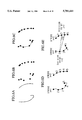
- FIG. 6A shows the real shape of a Japanese hiragana "i" as an example of a handwritten character
- FIG. 6B shows each writing point
- FIG. 6C shows interpolation of the writing points
- FIG. 6D shows the division of each stroke
- FIG. 6E is for the purpose of explaining the determination of matrix elements.
- FIG. 7 is a perspective view of the handwriting information detecting apparatus as a variation of the first embodiment.
- FIG. 8 is a perspective view of the handwriting information detecting apparatus of the second embodiment of the present invention holding a pencil.
- FIG. 9 is a perspective view of the detecting apparatus of FIG. 8 holding a pencil and being grasped by a user.
- FIG. 10 is a block diagram showing the handwriting recognition and display circuit of the detecting apparatus of FIG. 8.
- FIG. 11 is for the purpose of explaining a positional relationship between a pressure sensitive sensor fixed on an elastic beam which is projected from the body of the apparatus of FIG. 8, the index finger of a user, and a pencil.
- FIG. 12 shows an arrangement for the experiment used to examine condition of the detection of the detecting apparatus of FIG. 8.
- FIG. 13 shows the result of the above experiment.
- FIG. 14 shows a variation of the second embodiment, and explains a positional relationship between a strain gauge fixed on an elastic beam, the index finger of a user, and a pencil.
- FIG. 15 shows another variation of the second embodiment, and explains a positional relationship between a pair of a light-emitting element and a light-receiving element fixed on an elastic beam, the index finger of a user, and a pencil.
- FIG. 16 is a perspective view of the handwriting information detecting apparatus of the third embodiment of the present invention holding a pencil.
- FIG. 17 is a perspective view of the detecting apparatus of FIG. 16 holding a pencil and being grasped by a user.
- FIG. 18 is a partially cut-away perspective view showing the internal structure of the detecting apparatus of FIG. 16.
- FIG. 19 is for the purpose of explaining starting and end points of the motion of one stroke during writing a character according to the third embodiment.
- FIGS. 20A and 20B are for the purpose of explaining monitor images of the neighborhood of a starting point.
- FIG. 21 is for the purpose of explaining a monitor image of the neighborhood of an end point.
- FIG. 22 is a flow chart explaining the process for detecting motions of a pen by using the monitor images.
- FIG. 23 is a perspective view of the handwriting information detecting apparatus as a variation of the third embodiment.
- the handwriting information detecting apparatus as an embodiment of the present apparatus will be explained below.
- FIG. 1 is a perspective view of the apparatus holding a pencil
- FIG. 2 is a perspective view of the apparatus being grasped by fingers
- FIG. 3 is a partially cut-away perspective view showing the internal structure of the apparatus.
- reference symbol A indicates the handwriting information detecting apparatus of the present embodiment
- reference numeral 1 indicates the body of the apparatus functioning as a writing tool holder
- reference symbol ⁇ indicates a pencil as a suitable example of a writing tool
- reference symbol ⁇ indicates a hand
- reference symbols ⁇ a and ⁇ b indicate the index finger and the thumb of the hand, respectively.
- Reference numeral 2 indicates a plate
- reference numerals 3 and 4 indicate supporting pieces
- reference numeral 5 indicates a binding pin
- reference numeral 6 indicates a coil spring
- reference numeral 7 indicates a writing tool clamping part
- reference numeral 8 indicates an L-step part
- reference numeral 9 indicates an inclined part
- reference numerals 10 and 11 indicate ends of the L-step part 8 and the inclined part 9 respectively
- reference numeral 12 indicates a handwriting information recognition circuit
- reference numerals 13, 14, and 15 indicate X-, Y-, and Z-axis acceleration sensors respectively, the axes corresponding to those of the three dimensional rectangular coordinates
- reference numeral 20 indicates a power source.
- the handwriting information recognition circuit 12 includes an amplifier 16 for amplifying and outputting each signal output from each of the X-, Y-, and Z-axis acceleration sensors, a two-times integrator 17 for twice integrating each amplified signal output from each of X- and Y-axis acceleration sensors and outputting the integrated signals and the amplified signal of the Z-axis acceleration sensor, a handwriting information recognizer 18 for recognizing handwriting information by detecting the motions of the writing tool based on the outputs from the two-times integrator 17, and a signal transmitter 19 for outputting the handwriting information which was recognized by the handwriting information recognizer 18 to the outside of the apparatus.
- an amplifier 16 for amplifying and outputting each signal output from each of the X-, Y-, and Z-axis acceleration sensors
- a two-times integrator 17 for twice integrating each amplified signal output from each of X- and Y-axis acceleration sensors and outputting the integrated signals and the amplified signal of the Z-axis acceleration sensor
- supporting pieces 3 and 4 are combined by binding pin 5 and elastically urged by coil spring 6 so as to enable ends 10 and 11 to elastically open and close in a way similar to a clothes-pin. That is, as shown in FIG. 1, pencil ⁇ is clamped and held by writing tool clamping part 7 like the case of a clothes-pin.
- a ball-point pen As a writing tool to be clamped by writing tool clamping part 7, a ball-point pen, a mechanical pencil, a fountain pen, a writing brush, a marker pen, a water-paint pen, a paintbrush, and the like are also possible to choose in place of pencil ⁇ .
- Z-axis acceleration sensor 15 is arranged in a manner such that the direction of its axis is approximately made parallel to the line of the end 10 of the L-step part 8, that is, made approximately parallel to the direction of up and down motions of the writing tool grasped by the user.
- X- and Y-axis acceleration sensors 13 and 14 are arranged in a manner such that the direction of each axis is perpendicular to the axial direction of the Z-axis acceleration sensor 15 and that the axial directions of the X- and Y-axis acceleration sensors are also perpendicular to each other. These three sensors are built in the body 1.
- Power source 20 may have ordinary dry cells, or lithium, Ni--Cd, or air cells. Solar cells, which are attached on the body 1, may also be used.
- the up and down motions of pencil a are detected by using signal S Z output from Z-axis acceleration sensor 15.
- the down motion of the writing tool indicates a motion of lowering the writing tool so as its point touches the paper
- the up motion of the writing tool indicates a motion of raising the writing tool so as to remove its point from the paper.
- a "stroke" indicates a motion which occurs between a down motion and the following up motion of the writing tool.
- two thresholds for the down and up motions are provided for the level of signal S Z , and if the signal level exceeds the threshold for the up motion, it is judged that the up motion has occurred, while if the signal level exceeds the threshold for the down motion, it is judged that the down motion has occurred.
- the positive direction of Z-axis acceleration sensor 15 corresponds to
- one of the thresholds for the down and up motions is positive, and the other is negative.
- the absolute value of the signal varies in a manner such that the value exceeds the corresponding threshold.
- the absolute values of both thresholds may be different or may be the same.
- FIG. 4 shows the input process for writing points (i.e., points on the stroke)
- FIG. 5 shows the recognition process based on the inputted writing points.
- Each process is performed by handwriting information recognizer 18.
- step SP103 non-contact time r with regard to the pen and the object for writing (that is, the time in which the pen does not touch with the object) is measured (see steps SP105-SP107). Then, it is judged whether or not the non-contact time r is smaller than a preset value R (see step SP108), and when the non-contact time r reaches or exceeds this preset value R, it is recognized that handwriting input of all strokes of the character Cx has been completed, and the recognition process from step SP201 commences.
- a (k+1)N row ⁇ k ⁇ N column (where N is the number of strokes) matrix P consisting of elements is calculated, wherein the element of row ⁇ (k+1)(n 1 -1)+i ⁇ and column ⁇ k(n 2 -1)+j ⁇ comprises an angle ⁇ formed by means of a straight line joining division point i of stroke n 1 and division point j of stroke n 2 , and a straight line joining division point i of stroke n 1 and division point j+1 of stroke n 2 (see step SP203).
- this sum of the square is calculated by means of either taking the sum of the squares of all elements of "matrix P-matrix Qi", or taking the sum of the squares of a specific portion of the above matrix (e.g., the portion of elements calculated from the straight line connecting a division point of stroke n and a division point of stroke n+1).
- step SP104 of the input procedure shown in FIG. 4 components v X and v y of the velocity v of the pen point moving along each stroke may be input as coordinate data instead of coordinates of the writing point.
- templates corresponding to the velocity data must be previously stored.
- the recognized character information may be transmitted out from signal transmitter 19 in the form of character codes via a wireless or infrared system and be received by any external and ordinary computer which has a receiver for the information.
- the signal transmission from signal transmitter 19 may be performed via a wired system.
- the output from two-times integrator 17, that is, the result of the two-times integration, which is the locus of a character or figure itself, may be directly output from the signal transmitter 19 without recognizing the character or figure based on the above-mentioned writing points.
- FIG. 7 is a perspective view of handwriting information detecting apparatus B as a variation of apparatus A in FIG. 1.
- reference numeral 21 indicates a body of the apparatus
- reference numeral 22 indicates an indentation, provided at an end of the body 21, for holding a writing tool
- reference numeral 23 indicates screws for pressing and fixing the writing tool which is inserted in the indentation 22 by their points, via tapped holes 24 with spot facing which are provided outside body 21.
- the same acceleration sensors and the handwriting information recognition circuit as those of the apparatus A shown in FIG. 3 are internally provided and the procedures explained in the above "Method Example" are performed for recognizing the handwriting information.
- FIG. 8 is a perspective view of the handwriting information detecting apparatus of this embodiment holding a pencil
- FIG. 9 is a perspective view of the apparatus being grasped by fingers
- FIG. 10 is a block diagram showing the handwriting recognition and display circuit of the apparatus
- FIG. 11 is for the purpose of explaining a positional relationship between a pressure sensitive sensor fixed on a beam which is projected from the body of the apparatus, the index finger of a user, and the pencil.
- parts which are identical to those shown in FIGS. 1 ⁇ 3 are given identical reference numbers and an explanation thereof will be omitted here.
- reference symbol C indicates the handwriting information detecting apparatus of the present embodiment
- reference symbol ⁇ a' indicates the finger cushion of the tip of index finger ⁇ a
- reference numeral 31 indicates the body of the apparatus forming a curved step part 31a, the body functioning as a writing tool holder
- reference numeral 32 indicates an elastic beam, made of plastics and the like, which is projected from the curved step part 31a of the body 31.
- the finger cushion ⁇ a' of the index finger touches the end of the beam when the user grasps pencil ⁇ .
- Reference numeral 33 indicates a pressure sensitive sensor, fixed on the end of the elastic beam 32, for detecting the level of the pressure caused by finger cushion ⁇ a'.
- Reference numeral 34 indicates a character display, and a liquid crystal display is used in this embodiment.
- Reference numeral 36 indicates a writing tool holding part comprising a pair of rings 37 and 38 for inserting and holding the writing tool, a block nut 39 which is fixed between the lower ends of these rings, and a bolt 40 for fixing the writing tool.
- pencil ⁇ is inserted into rings 37 and 38 to a suitable position, and by fastening bolt 40, the pencil ⁇ is fixed to the apparatus C.
- reference numeral 51 indicates a handwriting recognition and display circuit which is built in the body 31.
- Reference numeral 55 indicates an amplifier for amplifying and outputting each signal output from each of X- and Y-axis acceleration sensors
- reference numeral 56 indicates a two-times integrator for twice integrating each amplified signal output from each of X- and Y-axis acceleration sensors and outputting the integrated signals
- reference numeral 57 indicates a handwriting information recognizer for recognizing handwriting information by detecting motions of the writing tool based on the outputs from the two-times integrator 56
- reference numeral 58 indicates a signal transmitter for outputting the handwriting information which was recognized by the handwriting information recognizer 57
- reference numeral 59 indicates a signal receiver which can receive signals transmitted from any external device.
- Reference numeral 61 indicates a CPU (central processing unit), connected to pressure sensitive sensor 33, for totally controlling the whole system including amplifier 55, two-times integrator 56, handwriting information recognizer 57, signal transmitter 58, and signal receiver 59, and reference numeral 62 indicates a power source, using solar cells 35 which are mounted on the body, for supplying drive current to the whole system.
- Power source 62 may have ordinary dry cells, or lithium, Ni--Cd, or air cells in the body. An external power source may also be used via an electric cable.
- the positional relationship between the index finger ⁇ a of the user, elastic beam 32, pressure sensitive sensor 33, and pencil ⁇ is such as shown in FIG. 8; thus, finger cushion ⁇ a' of the index finger ⁇ a touches with the pressure sensitive sensor 33.
- the up and down motions of pencil ⁇ to the paper etc. can be detected by processing a signal output from pressure sensitive sensor 33 mounted on elastic beam 32 based on thresholds, as the case of the first embodiment. That is to say, if the signal level exceeds a threshold for the down motion, that is, if the pressure exceeds a level, it is judged that the down motion has occurred, while if the signal level goes below a threshold for the up motion, that is, if the pressure goes below a level, it is judged that the up motion has occurred. According to this, it is possible to detect each remarkable point of the motions of the writing tool, such as a starting point of writing a character or a figure, the end point of writing a character or a figure, and the like.
- the output signal from the pressure sensitive sensor 33 has a negative characteristic, the judgment may be conducted such that if the signal exceeds a threshold in the negative direction, the motion is judged as a down motion.
- the recognized character information may be transmitted out from signal transmitter 59 in the form of character codes via a wireless or infrared system and be received by any external and ordinary computer which has a receiver for the information.
- the recognized result of the character written by the user is displayed on character display (liquid crystal display) 34; thus, the user can confirm the result.
- the present apparatus and method may be applied to an interactive pager.
- the message transmitted via a wireless or infrared system from a communication partner may be received by signal receiver 59, and it may also be possible to read the message on character display 34.
- the pen point of ball-point pen PB is made of metal; thus, while the pen point was in contact with the metal plate 65 (that is, in the down state of the pen), voltage of battery 66 was detected as signal S B .
- the output from pressure sensitive sensor 33 of apparatus C was detected as signal S A .
- FIG. 13 shows variations of both signals obtained from one stroke performed by a testee.
- the horizontal axis indicates “time”, while the vertical axis indicates “voltage”.
- signal S A has a negative characteristic.
- FIG. 14 shows a variation of apparatus C in FIG. 8, and explains a positional relationship between a strain gauge fixed on the elastic beam, the index finger of a user, and the pencil.
- reference numeral 73 indicates a strain gauge fixed on a part near the root of elastic beam 32. That is, in this variation, the strain gauge 73 is provided as a sensor for judging the up and down motions of pencil ⁇ , instead of pressure sensitive sensor 33 in FIG. 8.
- Other arrangements of the variation are the same as those of apparatus C.
- FIG. 15 shows another variation of the apparatus C, and explains a positional relationship between a pair of a light-emitting element and a light-receiving element fixed on the elastic beam, the index finger of a user, and the pencil.
- reference numerals 74 and 75 indicate a LED (light emitting diode) and a phototransistor respectively, as suitable examples of a pair of a light-emitting element and a light-receiving element. They are fixed on the end part of elastic beam 32. That is, in this variation, LED 74 and phototransistor 75 are provided instead of pressure sensitive sensor 33, and other arrangements of the variation are the same as those of apparatus C.
- near infrared light which is irradiated by LED 74 is scattered inside the finger, and a part of the scattered light is detected by phototransistor 75.
- the variation of the level of the detected light corresponds to the photoelectric pulse wave.
- the photoelectric pulse wave is explained such that the variation of blood pressure according to the beat of the heart is detected as a pulsation of the blood vessel.
- the differential pressure inside and outside the blood vessel of the artery decreases, the compliance of the artery increases; thus, the amplitude of the signal of the photoelectric pulse wave also increases (Hiraiwa et al., "Physiological Stress Change by Means of Noninvasive Measurement of Arterial Pressure and Mechanical Properties", the Proceedings of 3rd Symposium on Human Interface, pp. 61-66, the Society of Instrument and Control Engineers, 1987).
- the judgment can be performed such that if the amplitude exceeds a threshold, the down motion of pencil ⁇ has occurred, while if the amplitude goes below a threshold, the up motion of pencil ⁇ has occurred.
- the variation of the pressure acting on the finger cushion of the index finger of the user during the up or down motion of the writing tool is detected by an elastic beam and various kinds of sensors; thus, there is an advantage that the up and down motions of any writing tool can be certainly and easily detected.
- FIG. 16 is a perspective view of the handwriting information detecting apparatus of this embodiment holding a pencil
- FIG. 17 is a perspective view of the apparatus being grasped by fingers
- FIG. 18 is a partially cut-away perspective view showing the internal structure of the apparatus.
- parts which are identical to those shown in FIGS. 1 ⁇ 3 and FIGS. 8 ⁇ 10 are given identical reference numbers and an explanation thereof will be omitted here.
- reference symbol D indicates the handwriting information detecting apparatus of the present embodiment
- reference numeral 81 indicates the body of the apparatus functioning as a writing tool holder
- reference numeral 81a indicates a CCD (charge coupled device) container which is formed as a part of the body 81
- Reference numeral 98 indicates a CCD monitor camera as a suitable example of a photographic monitor means and is housed in the CCD container 81a.
- Reference numeral 95 indicates a CPU, connected to CCD monitor camera 98, for totally controlling the whole system including amplifier 55, two-times integrator 56, handwriting information recognizer 57, and signal transmitter 58
- reference numeral 96 indicates a power source for supplying drive current to the whole system.
- the apparatus D has the same mechanism as that of apparatus A. As shown in FIG. 16, pencil ⁇ is clamped and held by writing tool clamping part 7. Here, a suitable holding position is chosen for monitoring images of the neighborhood of the point of pencil ⁇ by CCD monitor camera 98.
- the manner of using pencil ⁇ by a user is similar to that of apparatus A, and the direction of apparatus D when the user grasps pencil ⁇ is also always approximately fixed; thus, the axial directions of X- and Y-axis acceleration sensors 13 and 14 are aligned in pre-determined directions approximately.
- FIG. 19 is for the purpose of explaining the starting and end points of the motion of one stroke during writing a character
- FIGS. 20A and 20B are for the purpose of explaining monitor images of the area around a starting point
- FIG. 21 is for the purpose of explaining a monitor image of the area around an end point
- FIG. 22 is a flow chart explaining the process for detecting motions of a pen by using the monitor images.
- CPU 95 takes charge of the timing control between the parts of the system.
- One stroke ST during writing a character has a writing starting point S and a writing end point E.
- CCD monitor camera 98 takes pictures of the view of neighborhood of pen point ⁇ 1, as shown in FIG. 20A.
- the dotted circle near the center of the circular monitor image MD will be called as center circle SC.
- CCD camera 98 takes up an image of time t, as shown in FIG. 20A (see step SP1).
- step SP2 When the micro-time ⁇ t passes from time t, a similar image is taken up again (see step SP2). The difference between the above two images is then calculated (see step SP3).
- T time
- T time
- time t is recognized as the starting point of a stroke.
- time t is recognized as the end point of a stroke.
- a signal receiver as embodiment 2 so as to receive signals transmitted from an external device like a pager and to display the information corresponding to the signals on the above display.
- Another method of using an image pick-up tube monitor and the like is possible for taking monitor image MD around the pen point ⁇ 1, besides the method of using CCD as the present embodiment.
- FIG. 23 is a perspective view of the handwriting information detecting apparatus E as a variation of apparatus D in FIG. 16.
- reference numeral 101 indicates a body of the apparatus
- reference numeral 101a indicates a CCD container which is formed as a part of the body 101.
- Reference numeral 102 indicates an indentation, provided at an end of the body 101, for holding a writing tool
- reference numeral 103 indicates screws for pressing and fixing the writing tool which is inserted in the indentation 102 by their points, via tapped holes 104 provided outside body 101.
- the CCD monitor camera contained in the apparatus monitors and takes pictures of the neighborhood of the pen point of the writing tool and the handwriting information is detected based on the monitored images; thus, there is an advantage that the up and down motions of any writing tool can be certainly recognized.
Abstract
Description
Claims (37)
Applications Claiming Priority (6)
| Application Number | Priority Date | Filing Date | Title |
|---|---|---|---|
| JP6-147415 | 1994-06-29 | ||
| JP6147415A JPH0816301A (en) | 1994-06-29 | 1994-06-29 | Method and device for inputting hand-writing information |
| JP15696994A JP3351449B2 (en) | 1994-07-08 | 1994-07-08 | Writing implement lifting judgment processing method |
| JP6-156969 | 1994-07-08 | ||
| JP6172756A JPH0836461A (en) | 1994-07-25 | 1994-07-25 | Method for deciding and processing various kinds of tip of pen and handwriting information input device with monitor |
| JP6-172756 | 1994-07-25 |
Publications (1)
| Publication Number | Publication Date |
|---|---|
| US5781661A true US5781661A (en) | 1998-07-14 |
Family
ID=27319348
Family Applications (1)
| Application Number | Title | Priority Date | Filing Date |
|---|---|---|---|
| US08/495,837 Expired - Fee Related US5781661A (en) | 1994-06-29 | 1995-06-28 | Handwritting information detecting method and apparatus detachably holding writing tool |
Country Status (1)
| Country | Link |
|---|---|
| US (1) | US5781661A (en) |
Cited By (42)
| Publication number | Priority date | Publication date | Assignee | Title |
|---|---|---|---|---|
| WO1999052060A2 (en) * | 1998-04-07 | 1999-10-14 | Black Gerald R | Identification confirmation system |
| US6130666A (en) * | 1996-10-07 | 2000-10-10 | Persidsky; Andre | Self-contained pen computer with built-in display |
| US6212296B1 (en) * | 1997-12-23 | 2001-04-03 | Ricoh Company, Ltd. | Method and apparatus for transforming sensor signals into graphical images |
| WO2001050411A1 (en) * | 2000-01-06 | 2001-07-12 | Zen Optical Technology Llc | Pen-based handwritten character recognition and storage system |
| WO2001088859A2 (en) * | 2000-05-18 | 2001-11-22 | Stefaan De Schrijver | Smartchip biometric device |
| WO2001091061A2 (en) * | 2000-05-19 | 2001-11-29 | Stefaan De Schrijver | Biometric energy identification system |
| US20020025062A1 (en) * | 1998-04-07 | 2002-02-28 | Black Gerald R. | Method for identity verification |
| US20030091217A1 (en) * | 1999-05-25 | 2003-05-15 | Kia Silverbrook | Signature capture via interface surface with coded marks |
| US6573887B1 (en) * | 1996-04-22 | 2003-06-03 | O'donnell, Jr. Francis E. | Combined writing instrument and digital documentor |
| US20030214489A1 (en) * | 2002-05-14 | 2003-11-20 | Woods Peter N. | Note and sketch transcription device, system, and method |
| US20040010910A1 (en) * | 2002-06-19 | 2004-01-22 | Brian Farrell | Chip package sealing method |
| US6686910B2 (en) * | 1996-04-22 | 2004-02-03 | O'donnell, Jr. Francis E. | Combined writing instrument and digital documentor apparatus and method of use |
| US20040164972A1 (en) * | 2003-02-24 | 2004-08-26 | Carl Stewart R. | Implement for optically inferring information from a planar jotting surface |
| US6831632B2 (en) | 2001-04-09 | 2004-12-14 | I. C. + Technologies Ltd. | Apparatus and methods for hand motion tracking and handwriting recognition |
| US6839453B1 (en) | 2000-05-16 | 2005-01-04 | The Upper Deck Company, Llc | Method and apparatus for authenticating unique items such as sports memorabilia |
| US20050122209A1 (en) * | 2003-12-03 | 2005-06-09 | Black Gerald R. | Security authentication method and system |
| US20050133700A1 (en) * | 2003-12-22 | 2005-06-23 | Buermann Dale H. | Method and apparatus for determining absolute position of a tip of an elongate object on a plane surface with invariant features |
| US20050150697A1 (en) * | 2002-04-15 | 2005-07-14 | Nathan Altman | Method and system for obtaining positioning data |
| US20050168437A1 (en) * | 2004-01-30 | 2005-08-04 | Carl Stewart R. | Processing pose data derived from the pose of an elongate object |
| US20050180618A1 (en) * | 1999-02-10 | 2005-08-18 | Black Gerald R. | Method for identity verification |
| US20050261972A1 (en) * | 2001-05-25 | 2005-11-24 | Black Gerald R | Pen-based transponder identity verification system |
| US20060005042A1 (en) * | 1999-09-17 | 2006-01-05 | Black Gerald R | Data security system |
| US20060023922A1 (en) * | 2001-05-25 | 2006-02-02 | Black Gerald R | Identity authentication device |
| US20060088215A1 (en) * | 1999-03-24 | 2006-04-27 | British Telecommunications, Public Limited Company | Handwriting recognition system |
| US20060215886A1 (en) * | 2000-01-24 | 2006-09-28 | Black Gerald R | Method for identity verification |
| US20090245646A1 (en) * | 2008-03-28 | 2009-10-01 | Microsoft Corporation | Online Handwriting Expression Recognition |
| US20100101873A1 (en) * | 2000-02-24 | 2010-04-29 | Silverbrook Research Pty Ltd | Method of estimating nib position using images captured at different pen rotations |
| US20100142325A1 (en) * | 2007-03-14 | 2010-06-10 | Epos Development Ltd. | Mems microphone |
| US20100146424A1 (en) * | 2008-12-08 | 2010-06-10 | Canon Kabushiki Kaisha | Information processing apparatus and method for presenting content of an instruction and an instruction locus |
| US20100166314A1 (en) * | 2008-12-30 | 2010-07-01 | Microsoft Corporation | Segment Sequence-Based Handwritten Expression Recognition |
| FR2942896A1 (en) * | 2009-03-03 | 2010-09-10 | Lionel Prevors | Removable computerized electronic device for use with e.g. fountain pen to automatically recognize handwritten text, has orifice covered with flexible polyurethane or silicone for permitting fixation of end of existing writing unit |
| US7826641B2 (en) | 2004-01-30 | 2010-11-02 | Electronic Scripting Products, Inc. | Apparatus and method for determining an absolute pose of a manipulated object in a real three-dimensional environment with invariant features |
| US20110096042A1 (en) * | 2005-03-23 | 2011-04-28 | Epos Development Ltd. | Method and system for digital pen assembly |
| US7961909B2 (en) | 2006-03-08 | 2011-06-14 | Electronic Scripting Products, Inc. | Computer interface employing a manipulated object with absolute pose detection component and a display |
| DE202013006303U1 (en) * | 2013-07-14 | 2014-10-16 | Joanna Kowalczyk | Digital pen and pen approach |
| US20140355885A1 (en) * | 2013-05-31 | 2014-12-04 | Kabushiki Kaisha Toshiba | Retrieving apparatus, retrieving method, and computer program product |
| US9042608B2 (en) | 2010-10-25 | 2015-05-26 | Pen-One, Inc. | Data security system |
| US9229540B2 (en) | 2004-01-30 | 2016-01-05 | Electronic Scripting Products, Inc. | Deriving input from six degrees of freedom interfaces |
| US9529971B2 (en) | 2011-01-11 | 2016-12-27 | Ingenico Group | Method for the electronic authenticating of a handwritten signature, corresponding module and computer program |
| CN106952456A (en) * | 2017-03-15 | 2017-07-14 | 深圳市松恩电子科技有限公司 | A kind of method and apparatus for writing monitoring |
| US11150750B2 (en) * | 2018-02-23 | 2021-10-19 | Wacom Co., Ltd. | Electronic pen and electronic pen main body unit |
| US11577159B2 (en) | 2016-05-26 | 2023-02-14 | Electronic Scripting Products Inc. | Realistic virtual/augmented/mixed reality viewing and interactions |
Citations (25)
| Publication number | Priority date | Publication date | Assignee | Title |
|---|---|---|---|---|
| US3145367A (en) * | 1959-07-27 | 1964-08-18 | Stanford Research Inst | Character recognition circuit |
| US3906444A (en) * | 1973-10-11 | 1975-09-16 | Stanford Research Inst | Special pen and system for handwriting recognition |
| US3915015A (en) * | 1974-03-18 | 1975-10-28 | Stanford Research Inst | Strain gauge transducer system |
| US3930229A (en) * | 1974-01-31 | 1975-12-30 | Stanford Research Inst | Handwriting system |
| US4040010A (en) * | 1975-11-06 | 1977-08-02 | Stanford Research Institute | Identification by handwriting verification |
| US4086576A (en) * | 1974-11-27 | 1978-04-25 | C. L. Instruments Limited | Axle load monitoring systems |
| US4142175A (en) * | 1978-06-12 | 1979-02-27 | International Business Machines Corporation | Pressure sensing device and transducer arrangement |
| US4156911A (en) * | 1975-11-18 | 1979-05-29 | Stanford Research Institute | Dynamic re-creation of signatures |
| US4345239A (en) * | 1980-06-20 | 1982-08-17 | International Business Machines Corporation | Apparatus for determining pen acceleration |
| US4513437A (en) * | 1982-06-30 | 1985-04-23 | International Business Machines Corporation | Data input pen for Signature Verification |
| JPS62140130A (en) * | 1985-12-13 | 1987-06-23 | Rand Computer:Kk | Pen type data input device |
| US4751741A (en) * | 1984-07-19 | 1988-06-14 | Casio Computer Co., Ltd. | Pen-type character recognition apparatus |
| US4856077A (en) * | 1986-04-28 | 1989-08-08 | Eric Rothfjell | Method of signature verification and device for carrying out the method |
| US4896543A (en) * | 1988-11-15 | 1990-01-30 | Sri International, Inc. | Three-axis force measurement stylus |
| US5018208A (en) * | 1990-04-02 | 1991-05-21 | Gladstone Karen S | Input device for dynamic signature verification systems |
| JPH03156519A (en) * | 1989-11-14 | 1991-07-04 | Matsushita Electric Ind Co Ltd | Pen type computer input device |
| US5107541A (en) * | 1985-11-05 | 1992-04-21 | National Research Development Corporation | Method and apparatus for capturing information in drawing or writing |
| JPH04195321A (en) * | 1990-11-27 | 1992-07-15 | Matsushita Electric Ind Co Ltd | Pen type computer input device |
| JPH04256009A (en) * | 1991-02-07 | 1992-09-10 | Sharp Corp | Position instructing device |
| JPH04282717A (en) * | 1991-03-12 | 1992-10-07 | Sharp Corp | Input device for information processing apparatus |
| US5215397A (en) * | 1991-04-01 | 1993-06-01 | Yashima Electric Co., Ltd. | Writing device for storing handwriting |
| US5294792A (en) * | 1991-12-31 | 1994-03-15 | Texas Instruments Incorporated | Writing tip position sensing and processing apparatus |
| JPH0695800A (en) * | 1992-09-17 | 1994-04-08 | Nippon Nesamatsuku Kk | Pen grip type input device |
| JPH06102995A (en) * | 1992-09-22 | 1994-04-15 | Nippon Nesamatsuku Kk | Pen grip type input device |
| JPH06139000A (en) * | 1992-10-23 | 1994-05-20 | Nippon Nesamatsuku Kk | Pen grip type inputting device |
-
1995
- 1995-06-28 US US08/495,837 patent/US5781661A/en not_active Expired - Fee Related
Patent Citations (26)
| Publication number | Priority date | Publication date | Assignee | Title |
|---|---|---|---|---|
| US3145367A (en) * | 1959-07-27 | 1964-08-18 | Stanford Research Inst | Character recognition circuit |
| US3906444A (en) * | 1973-10-11 | 1975-09-16 | Stanford Research Inst | Special pen and system for handwriting recognition |
| US3930229A (en) * | 1974-01-31 | 1975-12-30 | Stanford Research Inst | Handwriting system |
| US3915015A (en) * | 1974-03-18 | 1975-10-28 | Stanford Research Inst | Strain gauge transducer system |
| US4086576A (en) * | 1974-11-27 | 1978-04-25 | C. L. Instruments Limited | Axle load monitoring systems |
| US4040010A (en) * | 1975-11-06 | 1977-08-02 | Stanford Research Institute | Identification by handwriting verification |
| US4156911A (en) * | 1975-11-18 | 1979-05-29 | Stanford Research Institute | Dynamic re-creation of signatures |
| US4142175A (en) * | 1978-06-12 | 1979-02-27 | International Business Machines Corporation | Pressure sensing device and transducer arrangement |
| US4345239A (en) * | 1980-06-20 | 1982-08-17 | International Business Machines Corporation | Apparatus for determining pen acceleration |
| US4513437A (en) * | 1982-06-30 | 1985-04-23 | International Business Machines Corporation | Data input pen for Signature Verification |
| US4751741A (en) * | 1984-07-19 | 1988-06-14 | Casio Computer Co., Ltd. | Pen-type character recognition apparatus |
| US5107541A (en) * | 1985-11-05 | 1992-04-21 | National Research Development Corporation | Method and apparatus for capturing information in drawing or writing |
| JPS62140130A (en) * | 1985-12-13 | 1987-06-23 | Rand Computer:Kk | Pen type data input device |
| US4856077A (en) * | 1986-04-28 | 1989-08-08 | Eric Rothfjell | Method of signature verification and device for carrying out the method |
| US4896543A (en) * | 1988-11-15 | 1990-01-30 | Sri International, Inc. | Three-axis force measurement stylus |
| JPH03156519A (en) * | 1989-11-14 | 1991-07-04 | Matsushita Electric Ind Co Ltd | Pen type computer input device |
| US5018208A (en) * | 1990-04-02 | 1991-05-21 | Gladstone Karen S | Input device for dynamic signature verification systems |
| JPH04195321A (en) * | 1990-11-27 | 1992-07-15 | Matsushita Electric Ind Co Ltd | Pen type computer input device |
| JPH04256009A (en) * | 1991-02-07 | 1992-09-10 | Sharp Corp | Position instructing device |
| JPH04282717A (en) * | 1991-03-12 | 1992-10-07 | Sharp Corp | Input device for information processing apparatus |
| US5215397A (en) * | 1991-04-01 | 1993-06-01 | Yashima Electric Co., Ltd. | Writing device for storing handwriting |
| JPH05278390A (en) * | 1991-04-01 | 1993-10-26 | Yashima Denki Co Ltd | Memory pen |
| US5294792A (en) * | 1991-12-31 | 1994-03-15 | Texas Instruments Incorporated | Writing tip position sensing and processing apparatus |
| JPH0695800A (en) * | 1992-09-17 | 1994-04-08 | Nippon Nesamatsuku Kk | Pen grip type input device |
| JPH06102995A (en) * | 1992-09-22 | 1994-04-15 | Nippon Nesamatsuku Kk | Pen grip type input device |
| JPH06139000A (en) * | 1992-10-23 | 1994-05-20 | Nippon Nesamatsuku Kk | Pen grip type inputting device |
Non-Patent Citations (4)
| Title |
|---|
| Hiraiwa et al., "Physiological Stress Change by Means of Noninvasive Measurement of Arterial Pressure and Mechanical Properties", the Proceedings of 3rd Symposium on Human Interface, pp. 61-66 (1987). |
| Hiraiwa et al., Physiological Stress Change by Means of Noninvasive Measurement of Arterial Pressure and Mechanical Properties , the Proceedings of 3rd Symposium on Human Interface, pp. 61 66 (1987). * |
| Nabishima et al., "Reconstructing a Whole Picture from a Series of Partial Pictures", Technical Report of IEICE, 94(141):1-8 (1994). |
| Nabishima et al., Reconstructing a Whole Picture from a Series of Partial Pictures , Technical Report of IEICE, 94(141):1 8 (1994). * |
Cited By (97)
| Publication number | Priority date | Publication date | Assignee | Title |
|---|---|---|---|---|
| US6573887B1 (en) * | 1996-04-22 | 2003-06-03 | O'donnell, Jr. Francis E. | Combined writing instrument and digital documentor |
| US6686910B2 (en) * | 1996-04-22 | 2004-02-03 | O'donnell, Jr. Francis E. | Combined writing instrument and digital documentor apparatus and method of use |
| US6130666A (en) * | 1996-10-07 | 2000-10-10 | Persidsky; Andre | Self-contained pen computer with built-in display |
| US6212296B1 (en) * | 1997-12-23 | 2001-04-03 | Ricoh Company, Ltd. | Method and apparatus for transforming sensor signals into graphical images |
| WO1999052060A2 (en) * | 1998-04-07 | 1999-10-14 | Black Gerald R | Identification confirmation system |
| US7082213B2 (en) | 1998-04-07 | 2006-07-25 | Pen-One Inc. | Method for identity verification |
| US20020025062A1 (en) * | 1998-04-07 | 2002-02-28 | Black Gerald R. | Method for identity verification |
| US20050169504A1 (en) * | 1998-04-07 | 2005-08-04 | Black Gerald R. | Method for identity verification |
| WO1999052060A3 (en) * | 1998-04-07 | 1999-12-23 | Gerald R Black | Identification confirmation system |
| US20050180618A1 (en) * | 1999-02-10 | 2005-08-18 | Black Gerald R. | Method for identity verification |
| US7961917B2 (en) | 1999-02-10 | 2011-06-14 | Pen-One, Inc. | Method for identity verification |
| US20060088215A1 (en) * | 1999-03-24 | 2006-04-27 | British Telecommunications, Public Limited Company | Handwriting recognition system |
| US7054510B1 (en) * | 1999-03-24 | 2006-05-30 | British Telecommunications Public Limited Company | Handwriting recognition system |
| US20050177728A1 (en) * | 1999-05-25 | 2005-08-11 | Silverbrook Research Pty Ltd | System for registering a user with a sensing device using a form |
| US7106888B1 (en) * | 1999-05-25 | 2006-09-12 | Silverbrook Research Pty Ltd | Signature capture via interface surface |
| US7864162B2 (en) | 1999-05-25 | 2011-01-04 | Silverbrook Research Pty Ltd | Product having encoded authentication writing areas |
| US7010147B2 (en) | 1999-05-25 | 2006-03-07 | Silverbrook Research Pty Ltd | Signature capture via interface surface using processing sensor |
| US20030091216A1 (en) * | 1999-05-25 | 2003-05-15 | Kia Silverbrook | Signature capture via interface surface and sensor with identifier |
| US20060034496A1 (en) * | 1999-05-25 | 2006-02-16 | Silverbrook Research Pty Ltd | Information management system with authenticity check |
| US20080314653A1 (en) * | 1999-05-25 | 2008-12-25 | Silverbrook Research Pty Ltd | Product having encoded authentication writing areas |
| US7263225B2 (en) | 1999-05-25 | 2007-08-28 | Silverbrook Research Pty Ltd | Information management system with authenticity check |
| US7221781B2 (en) | 1999-05-25 | 2007-05-22 | Silverbrook Research Pty Ltd | System for registering a user with a sensing device using a form |
| US20030103657A1 (en) * | 1999-05-25 | 2003-06-05 | Kia Silverbrook | Signature capture via interface surface using processing sensor |
| US7139431B2 (en) | 1999-05-25 | 2006-11-21 | Silverbrook Research Pty Ltd | Signature capture via interface surface with coded marks |
| US7133557B2 (en) | 1999-05-25 | 2006-11-07 | Silverbrook Research Pty Ltd | Signature capture via interface surface and sensor with identifier |
| US20030091217A1 (en) * | 1999-05-25 | 2003-05-15 | Kia Silverbrook | Signature capture via interface surface with coded marks |
| US20050175222A1 (en) * | 1999-05-25 | 2005-08-11 | Silverbrook Research Pty Ltd | System for authorising a user to use a sensing device using a form |
| US8374402B2 (en) | 1999-09-17 | 2013-02-12 | Pen-One, Inc. | Data security system |
| US8520905B2 (en) | 1999-09-17 | 2013-08-27 | Pen-One, Inc. | Data security system |
| US20060005042A1 (en) * | 1999-09-17 | 2006-01-05 | Black Gerald R | Data security system |
| US7822232B2 (en) | 1999-09-17 | 2010-10-26 | Pen-One, Inc. | Data security system |
| US20050185842A1 (en) * | 2000-01-06 | 2005-08-25 | Williams David R. | Pen-based handwritten character recognition and storage system |
| US6968083B2 (en) | 2000-01-06 | 2005-11-22 | Zen Optical Technology, Llc | Pen-based handwritten character recognition and storage system |
| US7164793B2 (en) | 2000-01-06 | 2007-01-16 | Williams David R | Pen-based handwritten character recognition and storage system |
| US20010038711A1 (en) * | 2000-01-06 | 2001-11-08 | Zen Optical Technology, Llc | Pen-based handwritten character recognition and storage system |
| WO2001050411A1 (en) * | 2000-01-06 | 2001-07-12 | Zen Optical Technology Llc | Pen-based handwritten character recognition and storage system |
| US20060215886A1 (en) * | 2000-01-24 | 2006-09-28 | Black Gerald R | Method for identity verification |
| US7609862B2 (en) | 2000-01-24 | 2009-10-27 | Pen-One Inc. | Method for identity verification |
| US8319745B2 (en) | 2000-02-24 | 2012-11-27 | Silverbrook Research Pty Ltd | Method of estimating nib position using images captured at different pen rotations |
| US20100101873A1 (en) * | 2000-02-24 | 2010-04-29 | Silverbrook Research Pty Ltd | Method of estimating nib position using images captured at different pen rotations |
| US6839453B1 (en) | 2000-05-16 | 2005-01-04 | The Upper Deck Company, Llc | Method and apparatus for authenticating unique items such as sports memorabilia |
| US7027623B2 (en) | 2000-05-16 | 2006-04-11 | The Upper Deck Company, Llc | Apparatus for capturing an image |
| WO2001088859A2 (en) * | 2000-05-18 | 2001-11-22 | Stefaan De Schrijver | Smartchip biometric device |
| WO2001088859A3 (en) * | 2000-05-18 | 2002-03-21 | Schrijver Stefaan De | Smartchip biometric device |
| WO2001091061A3 (en) * | 2000-05-19 | 2002-04-04 | Schrijver Stefaan De | Biometric energy identification system |
| WO2001091061A2 (en) * | 2000-05-19 | 2001-11-29 | Stefaan De Schrijver | Biometric energy identification system |
| US20050083317A1 (en) * | 2001-04-09 | 2005-04-21 | I.C. + Technologies Ltd. | Apparatus and method for hand motion tracking and handwriting recognition |
| US7394460B2 (en) | 2001-04-09 | 2008-07-01 | I.C. + Technologies Ltd. | Apparatus and method for hand motion tracking and handwriting recognition |
| US7911457B2 (en) | 2001-04-09 | 2011-03-22 | I.C. + Technologies Ltd. | Apparatus and methods for hand motion detection and hand motion tracking generally |
| US8686976B2 (en) | 2001-04-09 | 2014-04-01 | I.C. + Technologies Ltd. | Apparatus and method for hand motion detection and hand motion tracking generally |
| US6831632B2 (en) | 2001-04-09 | 2004-12-14 | I. C. + Technologies Ltd. | Apparatus and methods for hand motion tracking and handwriting recognition |
| US20080260250A1 (en) * | 2001-04-09 | 2008-10-23 | I.C. + Technologies Ltd. | Apparatus and methods for hand motion detection and handwriting recognition generally |
| US20050261972A1 (en) * | 2001-05-25 | 2005-11-24 | Black Gerald R | Pen-based transponder identity verification system |
| US7281135B2 (en) | 2001-05-25 | 2007-10-09 | Pgn-One Inc. | Pen-based transponder identity verification system |
| US7609863B2 (en) | 2001-05-25 | 2009-10-27 | Pen-One Inc. | Identify authentication device |
| US20060023922A1 (en) * | 2001-05-25 | 2006-02-02 | Black Gerald R | Identity authentication device |
| US9195325B2 (en) | 2002-04-15 | 2015-11-24 | Qualcomm Incorporated | Method and system for obtaining positioning data |
| US8546706B2 (en) | 2002-04-15 | 2013-10-01 | Qualcomm Incorporated | Method and system for obtaining positioning data |
| US9446520B2 (en) | 2002-04-15 | 2016-09-20 | Qualcomm Incorporated | Method and system for robotic positioning |
| US20050150697A1 (en) * | 2002-04-15 | 2005-07-14 | Nathan Altman | Method and system for obtaining positioning data |
| US20030214489A1 (en) * | 2002-05-14 | 2003-11-20 | Woods Peter N. | Note and sketch transcription device, system, and method |
| US7102625B2 (en) * | 2002-05-14 | 2006-09-05 | Woods Peter N | Note and sketch transcription device, system, and method |
| US20040010910A1 (en) * | 2002-06-19 | 2004-01-22 | Brian Farrell | Chip package sealing method |
| US20040164972A1 (en) * | 2003-02-24 | 2004-08-26 | Carl Stewart R. | Implement for optically inferring information from a planar jotting surface |
| US7203384B2 (en) | 2003-02-24 | 2007-04-10 | Electronic Scripting Products, Inc. | Implement for optically inferring information from a planar jotting surface |
| US7363505B2 (en) | 2003-12-03 | 2008-04-22 | Pen-One Inc | Security authentication method and system |
| US20050122209A1 (en) * | 2003-12-03 | 2005-06-09 | Black Gerald R. | Security authentication method and system |
| US7088440B2 (en) | 2003-12-22 | 2006-08-08 | Electronic Scripting Products, Inc. | Method and apparatus for determining absolute position of a tip of an elongate object on a plane surface with invariant features |
| US20050133700A1 (en) * | 2003-12-22 | 2005-06-23 | Buermann Dale H. | Method and apparatus for determining absolute position of a tip of an elongate object on a plane surface with invariant features |
| US9235934B2 (en) | 2004-01-30 | 2016-01-12 | Electronic Scripting Products, Inc. | Computer interface employing a wearable article with an absolute pose detection component |
| US8542219B2 (en) | 2004-01-30 | 2013-09-24 | Electronic Scripting Products, Inc. | Processing pose data derived from the pose of an elongate object |
| US9939911B2 (en) | 2004-01-30 | 2018-04-10 | Electronic Scripting Products, Inc. | Computer interface for remotely controlled objects and wearable articles with absolute pose detection component |
| US10191559B2 (en) | 2004-01-30 | 2019-01-29 | Electronic Scripting Products, Inc. | Computer interface for manipulated objects with an absolute pose detection component |
| US20050168437A1 (en) * | 2004-01-30 | 2005-08-04 | Carl Stewart R. | Processing pose data derived from the pose of an elongate object |
| US9229540B2 (en) | 2004-01-30 | 2016-01-05 | Electronic Scripting Products, Inc. | Deriving input from six degrees of freedom interfaces |
| US7826641B2 (en) | 2004-01-30 | 2010-11-02 | Electronic Scripting Products, Inc. | Apparatus and method for determining an absolute pose of a manipulated object in a real three-dimensional environment with invariant features |
| US20110096042A1 (en) * | 2005-03-23 | 2011-04-28 | Epos Development Ltd. | Method and system for digital pen assembly |
| US20110096044A1 (en) * | 2005-03-23 | 2011-04-28 | Epos Development Ltd. | Method and system for digital pen assembly |
| US8963890B2 (en) | 2005-03-23 | 2015-02-24 | Qualcomm Incorporated | Method and system for digital pen assembly |
| US9632627B2 (en) * | 2005-03-23 | 2017-04-25 | Qualcomm Incorporated | Method and system for digital pen assembly |
| US20110096043A1 (en) * | 2005-03-23 | 2011-04-28 | Epos Development Ltd. | Method and system for digital pen assembly |
| US8553935B2 (en) | 2006-03-08 | 2013-10-08 | Electronic Scripting Products, Inc. | Computer interface employing a manipulated object with absolute pose detection component and a display |
| US7961909B2 (en) | 2006-03-08 | 2011-06-14 | Electronic Scripting Products, Inc. | Computer interface employing a manipulated object with absolute pose detection component and a display |
| US20100142325A1 (en) * | 2007-03-14 | 2010-06-10 | Epos Development Ltd. | Mems microphone |
| US8861312B2 (en) | 2007-03-14 | 2014-10-14 | Qualcomm Incorporated | MEMS microphone |
| US20090245646A1 (en) * | 2008-03-28 | 2009-10-01 | Microsoft Corporation | Online Handwriting Expression Recognition |
| US20100146424A1 (en) * | 2008-12-08 | 2010-06-10 | Canon Kabushiki Kaisha | Information processing apparatus and method for presenting content of an instruction and an instruction locus |
| US20100166314A1 (en) * | 2008-12-30 | 2010-07-01 | Microsoft Corporation | Segment Sequence-Based Handwritten Expression Recognition |
| FR2942896A1 (en) * | 2009-03-03 | 2010-09-10 | Lionel Prevors | Removable computerized electronic device for use with e.g. fountain pen to automatically recognize handwritten text, has orifice covered with flexible polyurethane or silicone for permitting fixation of end of existing writing unit |
| US9042608B2 (en) | 2010-10-25 | 2015-05-26 | Pen-One, Inc. | Data security system |
| US9529971B2 (en) | 2011-01-11 | 2016-12-27 | Ingenico Group | Method for the electronic authenticating of a handwritten signature, corresponding module and computer program |
| US9195887B2 (en) * | 2013-05-31 | 2015-11-24 | Kabushiki Kaisha Toshiba | Retrieving apparatus, retrieving method, and computer program product |
| US20140355885A1 (en) * | 2013-05-31 | 2014-12-04 | Kabushiki Kaisha Toshiba | Retrieving apparatus, retrieving method, and computer program product |
| DE202013006303U1 (en) * | 2013-07-14 | 2014-10-16 | Joanna Kowalczyk | Digital pen and pen approach |
| US11577159B2 (en) | 2016-05-26 | 2023-02-14 | Electronic Scripting Products Inc. | Realistic virtual/augmented/mixed reality viewing and interactions |
| CN106952456A (en) * | 2017-03-15 | 2017-07-14 | 深圳市松恩电子科技有限公司 | A kind of method and apparatus for writing monitoring |
| US11150750B2 (en) * | 2018-02-23 | 2021-10-19 | Wacom Co., Ltd. | Electronic pen and electronic pen main body unit |
Similar Documents
| Publication | Publication Date | Title |
|---|---|---|
| US5781661A (en) | Handwritting information detecting method and apparatus detachably holding writing tool | |
| US6104388A (en) | Handwriting input device | |
| US8830212B2 (en) | System and method for digital recording of handpainted, handdrawn and handwritten information | |
| US6130666A (en) | Self-contained pen computer with built-in display | |
| EP0696019B1 (en) | Apparatus for verifying a handwriting | |
| JP2726594B2 (en) | Memory pen | |
| EP0953934B1 (en) | Pen like computer pointing device | |
| EP0649549B1 (en) | Apparatus and method of imaging written information | |
| US20060028457A1 (en) | Stylus-Based Computer Input System | |
| EP0503148A1 (en) | Tablet digitalizer with untethered stylus | |
| US20150015489A1 (en) | System and method for digital recording of handpainted, handdrawn and handwritten information | |
| US20040114834A1 (en) | Handwritten character recording and recognition device | |
| US6330359B1 (en) | Pen-grip type of input apparatus using finger pressure and gravity switches for character recognition | |
| WO2001035329A1 (en) | Apparatus for digitizing writing and drawing with erasing and/or pointing capability | |
| CN100416474C (en) | Rapid input device | |
| KR100360477B1 (en) | Wireless electronic pen | |
| JP3351449B2 (en) | Writing implement lifting judgment processing method | |
| JP3045891B2 (en) | Handwriting input device | |
| KR20070042858A (en) | Digital input device with pen-type | |
| JP3310398B2 (en) | Handwriting data input device and handwriting data recognition system using the same | |
| JPH0816301A (en) | Method and device for inputting hand-writing information | |
| Bernardin et al. | A hidden markov model based sensor fusion approach for recognizing continuous human grasping sequences | |
| JP2003114754A (en) | Device for inputting hand-written information | |
| JPH0836461A (en) | Method for deciding and processing various kinds of tip of pen and handwriting information input device with monitor | |
| Paulson et al. | Office activity recognition using hand posture cues |
Legal Events
| Date | Code | Title | Description |
|---|---|---|---|
| AS | Assignment |
Owner name: NIPPON TELEGRAPH AND TELEPHONE CORPORATION, JAPAN Free format text: ASSIGNMENT OF ASSIGNORS INTEREST;ASSIGNORS:HIRAIWA, AKIRA;FUKUMOTO, MASAAKI;UCHIYAMA, TADASU;AND OTHERS;REEL/FRAME:007551/0838 Effective date: 19950615 |
|
| AS | Assignment |
Owner name: NIPPON TELEGRAPH & TELEPHONE CORPORATION, JAPAN Free format text: CHANGE OF ADDRESS OF ASSIGNEE;ASSIGNOR:NIPPON TELEGRAPH & TELEPHONE CORPORATION;REEL/FRAME:008120/0588 Effective date: 19950918 |
|
| FEPP | Fee payment procedure |
Free format text: PAYOR NUMBER ASSIGNED (ORIGINAL EVENT CODE: ASPN); ENTITY STATUS OF PATENT OWNER: LARGE ENTITY |
|
| FPAY | Fee payment |
Year of fee payment: 4 |
|
| FPAY | Fee payment |
Year of fee payment: 8 |
|
| REMI | Maintenance fee reminder mailed | ||
| LAPS | Lapse for failure to pay maintenance fees | ||
| STCH | Information on status: patent discontinuation |
Free format text: PATENT EXPIRED DUE TO NONPAYMENT OF MAINTENANCE FEES UNDER 37 CFR 1.362 |
|
| FP | Lapsed due to failure to pay maintenance fee |
Effective date: 20100714 |