US5815572A - Video scrambling - Google Patents
Video scrambling Download PDFInfo
- Publication number
- US5815572A US5815572A US08/522,624 US52262495A US5815572A US 5815572 A US5815572 A US 5815572A US 52262495 A US52262495 A US 52262495A US 5815572 A US5815572 A US 5815572A
- Authority
- US
- United States
- Prior art keywords
- scrambling
- line
- video
- lines
- video signal
- Prior art date
- Legal status (The legal status is an assumption and is not a legal conclusion. Google has not performed a legal analysis and makes no representation as to the accuracy of the status listed.)
- Expired - Lifetime
Links
- 230000005540 biological transmission Effects 0.000 claims abstract description 9
- 238000000034 method Methods 0.000 claims description 8
- 238000001514 detection method Methods 0.000 description 6
- 230000005236 sound signal Effects 0.000 description 6
- 101710145505 Fiber protein Proteins 0.000 description 4
- 239000013598 vector Substances 0.000 description 4
- 238000013459 approach Methods 0.000 description 3
- 230000001360 synchronised effect Effects 0.000 description 3
- 230000000737 periodic effect Effects 0.000 description 2
- 238000012545 processing Methods 0.000 description 2
- 239000000872 buffer Substances 0.000 description 1
- 239000000969 carrier Substances 0.000 description 1
- 238000004891 communication Methods 0.000 description 1
- 238000005336 cracking Methods 0.000 description 1
- 230000001934 delay Effects 0.000 description 1
- 230000003111 delayed effect Effects 0.000 description 1
- 238000012986 modification Methods 0.000 description 1
- 230000004048 modification Effects 0.000 description 1
- 230000002265 prevention Effects 0.000 description 1
- 238000006467 substitution reaction Methods 0.000 description 1
- 230000001629 suppression Effects 0.000 description 1
- 238000012360 testing method Methods 0.000 description 1
Images


Classifications
-
- H—ELECTRICITY
- H04—ELECTRIC COMMUNICATION TECHNIQUE
- H04N—PICTORIAL COMMUNICATION, e.g. TELEVISION
- H04N7/00—Television systems
- H04N7/16—Analogue secrecy systems; Analogue subscription systems
- H04N7/167—Systems rendering the television signal unintelligible and subsequently intelligible
- H04N7/169—Systems operating in the time domain of the television signal
- H04N7/1696—Systems operating in the time domain of the television signal by changing or reversing the order of active picture signal portions
-
- H—ELECTRICITY
- H04—ELECTRIC COMMUNICATION TECHNIQUE
- H04N—PICTORIAL COMMUNICATION, e.g. TELEVISION
- H04N7/00—Television systems
- H04N7/16—Analogue secrecy systems; Analogue subscription systems
- H04N7/167—Systems rendering the television signal unintelligible and subsequently intelligible
- H04N7/171—Systems operating in the amplitude domain of the television signal
- H04N7/1716—Systems operating in the amplitude domain of the television signal by inverting the polarity of active picture signal portions
Definitions
- the invention concerns scrambling of video signals, such as those used in cable television, for security purposes.
- Services which transmit television signals on various channels, such as satellite links and cable television networks.
- the services frequently scramble the signals, in order to prevent unauthorized parties from gaining access to the signals.
- an improved video scrambling system which is simple to implement, but difficult to crack, is provided.
- multiple modes of video scrambling are available to a scrambler, including (i) line inversion, (ii) line reversal, (iii) line permutation, and (iv) block permutation.
- the invention changes the combination of modes used during operation.
- the combination of scrambling modes used is changed during operation, based on (i) amount of noise in the transmission channel, and (ii) amount of motion contained in the video image scrambled.
- decoding of the scrambled image is done by using tables, which are somewhat analogous to encryption "keys" used in de-crypting encrypted data.
- the scrambling codes are changed during operation, requiring the tables used be changed also.
- the contents of the tables are changed during operation, by downloading new data.
- FIG. 1 illustrates line reversal of a video signal
- FIG. 2 illustrates permutation of lines in a video signal
- FIG. 3 illustrates inversion of lines in a video signal
- FIG. 4 illustrates permutation of blocks in a video signal
- FIG. 5 illustrates a combination of line reversal, line permutation, line inversion, and block permutation
- FIG. 6 illustrates a high-level architecture representing one form of the invention
- FIG. 7 illustrates reconstruction of a block of lines, using the LINE PERMUTATION TABLE
- FIG. 8 illustrates use of three types of TABLEs by the invention
- FIG. 9 illustrates, by four examples, the large number of combinations of scrambling possible under the invention.
- FIG. 10 illustrates the division of a video signal into FRAMEs, which contain LINEs, which are composed of PIXELs;
- FIG. 11 illustrates commands which are issued, to order a DECODER to change the tables being used
- FIG. 12 illustrates commands ordering the DECODER to change tables being used, and, in addition, commands which change data contained within tables themselves;
- FIG. 13 illustrates detection of NOISE SPIKEs which occur between SYNCH PULSEs.
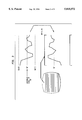
- FIG. 1 illustrates a television screen S, showing 20 scanning LINEs.
- FIG. 1 is, of course, a simplification, in that television images typically contain far more than twenty lines.
- NTSC National Television Standards Committee
- a typical screen contains 525 scanning lines, not twenty.
- FIG. 1 depicts line reversal, which involves flipping a line, end-for-end.
- Right (R) becomes left (L), and left becomes right, as indicated.
- the dots indicate the original right side of each line, for reference in later Figures.
- line reversal involves reversing the order of transmission of the data.
- Line permutation is represented in FIG. 2.
- the lines are collected into groups, or blocks B.
- Each block contains five lines.
- the parameter five is chosen for simplicity of explanation.
- the invention is not restricted to five lines per block. In one mode of operation, the invention can handle 32 lines per block.
- permutation the ordering of the lines is changed, or permuted, within each block. For example, in FIG. 2, the normal order (1, 2, 3, etc.) is permuted into the order (3, 2, 5, 1, 4). The lines are transmitted in this permuted order.
- FIG. 3 shows line inversion. Each LINE is generated by a luminance signal 10.
- the higher values of the luminance signal represent BLACK levels, as indicated, and the lower values indicate WHITE levels. Intermediate levels range from light grey to dark grey.
- Inversion involves changing black to white, and white to black. (Conceptually, inversion resembles converting a photograph into a negative of the photograph.) Inversion can be viewed as generating a mirror-image of the luminance signal about a reference REF, as indicated in the Figure.
- inversion can be accomplished by subtracting each point of the luminance signal from the reference value REF, and multiplying the result by a negative number. In addition, another number can be added, in order to level-shift the result.
- inversion can be accomplished by running the luminance signal through an inverting operational amplifier.
- Such an amplifier has a negative gain.
- Block permutation resembles line permutation.
- the lines are grouped into BLOCKs of five lines each, as shown in FIG. 4.
- the BLOCKs themselves are then permuted, as indicated.
- block permutation is not used.
- BLOCKs Two BLOCKs, of five lines each, and labeled BLOCK 1 and BLOCK 2, are taken from the screen S. LINE REVERSAL is performed first (although need not be first). Then, in each BLOCK, LINE PERMUTATION is imposed. Next, in each block, LINE INVERSION is undertaken. Inverted lines are indicated by dashing. Then, BLOCK PERMUTATION is done. The two resulting BLOCKs within box 20 represent the scrambled signal which is to be transmitted.
- the information within box 20 is transmitted as follows.
- the lines in BLOCK 2 are first transmitted, from top-to-bottom (that is, in the sequence 3, 2, 5, 1, 4), with each line being transmitted from left (L) to right (R).
- BLOCK 2 is transmitted in the same way.
- a receiver of this signal receives a signal which is scrambled.
- FIG. 6 illustrates a SCRAMBLER which performs the operations summarized in FIG. 5.
- the SCRAMBLER transmits the information along a COMMUNICATION CHANNEL, such as a cable television network, or satellite link, to a DECODER.
- a COMMUNICATION CHANNEL such as a cable television network, or satellite link
- the DECODER is located at a receiver (not shown), such as a customer's home, and reconstructs the original image.
- the DECODER uses four TABLES, shown in the Figure, to reconstruct the image. These TABLEs are stored in memory to which the DECODER has access.
- the LINE PERMUTATION TABLE tells how to re-order the lines. For example, in FIG. 5, the lines of each BLOCK are received in the order 3, 2, 5, 1, 4.
- the LINE PERMUTATION TABLE in FIG. 7 allows the DECODER to determine that
- the first line received is actually the third line on the screen
- the second line received is actually the second line on the screen, and so on.
- the LINE PERMUTATION TABLE allows the lines of each block to be arranged in the proper order.
- the DECODER contains other Tables, as indicated in FIG. 6, and also in FIG. 8.
- the LINE REVERSAL TABLE indicates, for each line in a block, whether the line is reversed.
- a ZERO indicates no reversal ("N” in the Figure) while a ONE indicates reversal ("Y").
- a LINE INVERSION TABLE indicates, for each line in a block, whether the line is inverted or not.
- a ZERO indicates inversion, a ONE indicates inversion.
- Each line of a block is processed as indicated by the arrows in FIG. 8. To repeat: the actual position of each line within the block (and thus on the screen) is ascertained from the LINE PERMUTATION TABLE. Whether the line must be reversed or inverted, or both, is ascertained from the LINE REVERSAL TABLE and the LINE INVERSION TABLE, respectively.
- the BLOCK PERMUTATION TABLE (FIG. 6) indicates how the blocks should be ordered.
- the TABLE used for scrambling and de-scrambling each mode is changed during operation. Some examples will illustrate.
- FIG. 9 illustrates four columns, running from left to right.
- the first column shows four different LINE PERMUTATION TABLES, labeled TABLE 1 through TABLE 4, which are contained within the DECODER of FIG. 6.
- the other columns show (a) four different LINE REVERSAL TABLES, (b) four different LINE INVERSION TABLES, and (c) four different BLOCK PERMUTATION TABLES. All are contained within the DECODER.
- FIG. 10 illustrates the data transmitted by the SCRAMBLER to the DECODER.
- a sequence of blocks B is transmitted.
- the blocks B are grouped into FRAMEs, as indicated. (The FRAMEs may be subdivided into fields, not shown, which are interlaced. This subdivision does not change the principles of the invention.)
- Each BLOCK B contains LINEs, as indicated.
- Each LINE as indicated, contains digital data which represents the pixels contained within the line.
- the LINEs and BLOCKs are scrambled, according to the four modes discussed above.
- the SCRAMBLER transmits codes which identify the TABLEs to be used for de-scrambling of subsequent frames.
- codes which identify the TABLEs to be used for de-scrambling of subsequent frames.
- the group of codes labeled 30 specify use of
- FIG. 9 Examples of such TABLEs are shown in FIG. 9.
- the group of codes 30 in FIG. 11 specifies the type of de-scrambling for all subsequent FRAMEs.
- group 33 another group of codes, such as group 33, can be transmitted, which specify another combination of TABLEs to use, for subsequent FRAMEs.
- the SCRAMBLER transmits codes at intervals (which need not be periodic, but can be) which specify the TABLES to use for de-scrambling of subsequent FRAMEs.
- FIG. 9 shows four BLOCK PERMUTATION TABLEs (BPT). However, the number of possible BPTs is much greater than four.
- Each frame, containing 525 lines, is generally divided into two fields, by interlacing. Each field contains about 112 lines. If each field is divided into blocks of five lines each, then 21 blocks will contain these 112 lines.
- the other TABLES also contain large number of possibilities, but not so large as the BPT. Therefore, rather than store all possible tables within the DECODER, the invention transmits contents of the TABLEs at intervals, from the SCRAMBLER.
- FIG. 12 illustrates this concept.
- the group of data labeled 36 instructs the DECODER to replace the data in LPT 1 with data which is presently transmitted, and indicated by the phrase "(DATA)". Similarly, data in the other TABLES are replaced.
- Frames are divided into fields, which are divided into blocks of lines. Five lines per block are preferred.
- the lines within a block are scrambled in four modes, namely, line permutation, line reversal, and line inversion.
- the blocks themselves are scrambled, in block permutation, providing a fourth mode of scrambling.
- De-scrambling which is done at a DECODER, is done according to identical TABLES.
- the contents of the TABLEs can be changed by the ENCODER.
- the ENCODER sends a message to the DECODER which specifies the TABLEs to be changed.
- the message includes data which is to replace the data previously contained within the specified TABLEs.
- the TABLEs can be specified as usual, by messages sent between frames.
- video images can be divided into two types: those containing little motion (such as a landscape), and those containing much motion (such as a basketball game). It has been found that images containing little motion do not scramble well using rudimentary scrambling techniques. Such techniques do not adequately disguise the image.
- line inversion alone does not scramble a low-motion image very well: the scrambled image will still be discernible. (On the other hand, line inversion is very effective in scrambling high-motion images.)
- FIG. 5 illustrates four modes of scrambling: LINE INVERSION, LINE PERMUTATION, LINE REVERSAL, and BLOCK PERMUTATION.
- Some video transmitters detect the amount of motion contained within an image, quantify the amount of motion, and generate a signal which indicates the amount of motion detected.
- IEEE standard H.261, IMPEG 2 concerns video conferencing.
- the transmitter of the video signal (such as a cable television station) includes motion vectors within the video signal. These motion vectors indicate the amount of motion contained within the image. Generation of the motion vectors is known in the art.
- the invention responds to the motion vectors by altering the scrambling.
- a greater number of scrambling modes are used.
- every line is inverted, as in FIG. 3, and the lines are randomly permuted (FIG. 2 illustrates permutation). No other scrambling is done.
- One goal of scrambling is to distort the video image. Another goal is to make the scrambling code difficult to crack, as by changing the code periodically.
- the inventor has derived the following general rule, for prevention of this unscrambling.
- line inversion is used, as shown in FIG. 3.
- Line permutation is also used, as shown in FIG. 2.
- the line permutation sequence is changed every two or three seconds.
- the channel carrying the video signal is contaminated by high electrical noise.
- decoding of line-reversed scrambling (line reversal is illustrated in FIG. 1) becomes difficult.
- the invention monitors the channel for noise, and avoids scrambling in the line-reversal mode, when noise exceeds a threshold.
- the invention infers noise from the presence of pulses which (a) exceed the synch pulses and (b) occur between actual synch pulses.
- FIG. 13 illustrates the detection of noise.
- the invention opens a DETECTION WINDOW, of suitable extent.
- the DETECTION WINDOW can extend between adjacent SYNCH PULSES.
- the invention then counts NOISE SPIKEs which are contained within the DETECTION WINDOW. These SPIKEs are defined as signals which exceed a threshold T, which preferably equals the SYNCH PULSE strength. If the number of NOISE SPIKEs counted exceeds a limit, during a prescribed time period, such as 60 frames (which, in this example, represents 60 DETECTION WINDOWS) , then excess noise is determined to be present.
- a threshold T which preferably equals the SYNCH PULSE strength.
- the invention avoids performing line-reversal.
- a cable television operator as opposed to the consumer, performs the test for excess noise.
- the operator informs the DECODER in FIG. 6, by an appropriate signal, when line reversal is being done.
- the DECODER responds by decoding line reversal, or not doing so, as appropriate.
- the video signal and the audio signal undergo different types of processing within the DECODER. Further, the two signals are carried by different carriers, which follow different signal paths. Consequently, the video signal and the audio signal will not arrive at their respective destinations at the same time.
- the finally processed video signal ready for display on a television monitor, will not be synchronous with the finally processed audio signal, ready for broadcast by a speaker. A time difference will exist.
- the invention determines this time difference, in order to synchronize the video with the audio.
- One approach to determining the time difference is to first generate two synchronous clocks, one in the SCRAMBLER, and one in the DECODER of FIG. 6. Then, the SCRAMBLER transmits a sample audio signal, and records the time of transmission. Assume this time to be T1.
- the DECODER receives the sample audio signal, and processes it, and records the time, T2, when processing has completed.
- the DECODER transmits the time T2 to the SCRAMBLER.
- the SCRAMBLER determines the time difference, T2-T1. Since the clocks which produced Ti and T2 are synchronous, the difference T2-T1 indicates the time difference between the video and audio signals.
- a similar procedure can be used to ascertain the video delay time. Based on the two delay times (audio and video), the invention computes the time by which the earlier signal must be delayed, in order to synchronize it with the later-arriving signal.
- the invention first ascertains the delay between the audio and video signal.
- One approach has been given above.
- Other approaches are known in the art.
- the invention buffers the earlier-arriving signal, or otherwise delays it, while awaiting arrival of the later signal. Then, the signals are delivered, in synchrony, to a receiver, such as a television set.
Abstract
Description
Claims (10)
Priority Applications (7)
| Application Number | Priority Date | Filing Date | Title |
|---|---|---|---|
| US08/522,624 US5815572A (en) | 1995-08-31 | 1995-08-31 | Video scrambling |
| CA002179787A CA2179787C (en) | 1995-08-31 | 1996-06-24 | Video scrambling |
| TW085108614A TW402855B (en) | 1995-08-31 | 1996-07-16 | Video scrambling |
| EP96306090A EP0762764B1 (en) | 1995-08-31 | 1996-08-21 | Video scrambling |
| DE69614952T DE69614952T2 (en) | 1995-08-31 | 1996-08-21 | video encryption |
| MX9603719A MX9603719A (en) | 1995-08-31 | 1996-08-28 | Video scrambling. |
| JP22802696A JP3708241B2 (en) | 1995-08-31 | 1996-08-29 | Video scrambling |
Applications Claiming Priority (1)
| Application Number | Priority Date | Filing Date | Title |
|---|---|---|---|
| US08/522,624 US5815572A (en) | 1995-08-31 | 1995-08-31 | Video scrambling |
Publications (1)
| Publication Number | Publication Date |
|---|---|
| US5815572A true US5815572A (en) | 1998-09-29 |
Family
ID=24081631
Family Applications (1)
| Application Number | Title | Priority Date | Filing Date |
|---|---|---|---|
| US08/522,624 Expired - Lifetime US5815572A (en) | 1995-08-31 | 1995-08-31 | Video scrambling |
Country Status (7)
| Country | Link |
|---|---|
| US (1) | US5815572A (en) |
| EP (1) | EP0762764B1 (en) |
| JP (1) | JP3708241B2 (en) |
| CA (1) | CA2179787C (en) |
| DE (1) | DE69614952T2 (en) |
| MX (1) | MX9603719A (en) |
| TW (1) | TW402855B (en) |
Cited By (13)
| Publication number | Priority date | Publication date | Assignee | Title |
|---|---|---|---|---|
| US6505299B1 (en) | 1999-03-01 | 2003-01-07 | Sharp Laboratories Of America, Inc. | Digital image scrambling for image coding systems |
| US20060120619A1 (en) * | 2004-12-06 | 2006-06-08 | Shmuel Avidan | Method for secure background modeling in images |
| US20060140490A1 (en) * | 2004-12-29 | 2006-06-29 | Anantharaman Balasubramanian | Method and apparatus for controlling access to image data |
| US20060227966A1 (en) * | 2005-04-08 | 2006-10-12 | Icera Inc. (Delaware Corporation) | Data access and permute unit |
| US7221761B1 (en) * | 2000-09-18 | 2007-05-22 | Sharp Laboratories Of America, Inc. | Error resilient digital video scrambling |
| US20070237328A1 (en) * | 2006-03-31 | 2007-10-11 | Hartmut Konig | Method for Encrypting Video Data |
| US8442221B2 (en) | 2005-09-30 | 2013-05-14 | Konica Minolta Laboratory U.S.A., Inc. | Method and apparatus for image encryption and embedding and related applications |
| US20160191853A1 (en) * | 2014-12-24 | 2016-06-30 | Cisco Technology, Inc. | Shuffled media content |
| US9479678B1 (en) * | 2013-11-07 | 2016-10-25 | Tencent Technology (Shenzhen) Company Limited | Method and device for image processing, and storage medium |
| US10305763B2 (en) | 2010-11-09 | 2019-05-28 | Vmware, Inc. | Monitoring audio fidelity and audio-video synchronization |
| US10453161B2 (en) | 2008-12-18 | 2019-10-22 | Vmware, Inc. | Watermarking and scalability techniques for a virtual desktop planning tool |
| US10623789B1 (en) * | 2011-03-14 | 2020-04-14 | Vmware, Inc. | Quality evaluation of multimedia delivery in cloud environments |
| US11056009B2 (en) | 2018-01-31 | 2021-07-06 | Performance Drone Works Llc | Secure control and operation of drones |
Families Citing this family (9)
| Publication number | Priority date | Publication date | Assignee | Title |
|---|---|---|---|---|
| JP4822304B2 (en) * | 1998-08-06 | 2011-11-24 | ソニー株式会社 | Image processing apparatus, image processing method, and recording medium |
| JP4182603B2 (en) | 1998-10-07 | 2008-11-19 | ソニー株式会社 | Encoding apparatus and encoding method, decoding apparatus and decoding method, recording medium, and data processing apparatus |
| JP3991249B2 (en) | 1998-07-15 | 2007-10-17 | ソニー株式会社 | Encoding apparatus and encoding method, decoding apparatus and decoding method, information processing apparatus and information processing method, and recording medium |
| US6965697B1 (en) | 1998-07-15 | 2005-11-15 | Sony Corporation | Coding apparatus and method, decoding apparatus and method, data processing system, storage medium, and signal |
| DE69943015D1 (en) * | 1998-10-07 | 2011-01-20 | Sony Corp | Method and device for image data coding with additional data insertion |
| KR100777144B1 (en) * | 1998-10-07 | 2007-11-19 | 소니 가부시끼 가이샤 | Coding apparatus and method, decoding apparatus and method, data processing system, storage medium, and recording medium |
| US6546139B1 (en) | 1998-10-07 | 2003-04-08 | Sony Corporation | Coding apparatus and method, decoding apparatus and method, data processing system, storage medium, and signal |
| DE19922155A1 (en) * | 1999-05-12 | 2000-11-23 | Giesecke & Devrient Gmbh | Memory arrangement and memory access procedure for microcomputers has an additional scrambling step to increase data security, for use in financial applications etc. |
| JP4670619B2 (en) * | 2005-12-07 | 2011-04-13 | 株式会社日立製作所 | Biological information verification system |
Citations (8)
| Publication number | Priority date | Publication date | Assignee | Title |
|---|---|---|---|---|
| US4245245A (en) * | 1975-02-24 | 1981-01-13 | Pioneer Electronic Corporation | Interactive CATV system |
| US4563702A (en) * | 1983-05-27 | 1986-01-07 | M/A-Com Linkabit, Inc. | Video signal scrambling and descrambling systems |
| US4827510A (en) * | 1986-02-24 | 1989-05-02 | Trw Inc. | Minimization of amplitude gaps in a line-spin scrambled video signal |
| US4916737A (en) * | 1988-11-14 | 1990-04-10 | Teleglobe Pay-Tv System, Inc. | Secure anti-piracy encoded television system and method |
| US4964162A (en) * | 1985-09-09 | 1990-10-16 | Trw Inc. | Secure television signal encoding and decoding system |
| US5185794A (en) * | 1990-08-06 | 1993-02-09 | Nec Home Electronics, Ltd. | System and method for scrambling and/or descrambling a video signal |
| US5268961A (en) * | 1992-08-20 | 1993-12-07 | General Electric Co. | Error control apparatus for a digital video signal processing system |
| US5321748A (en) * | 1992-07-02 | 1994-06-14 | General Instrument Corporation, Jerrold Communications | Method and apparatus for television signal scrambling using block shuffling |
Family Cites Families (3)
| Publication number | Priority date | Publication date | Assignee | Title |
|---|---|---|---|---|
| US4575754A (en) * | 1983-01-06 | 1986-03-11 | Rca Corporation | Video scrambler system |
| US4716588A (en) * | 1985-10-29 | 1987-12-29 | Payview Limited | Addressable subscription television system having multiple scrambling modes |
| US5091938B1 (en) * | 1990-08-06 | 1997-02-04 | Nippon Denki Home Electronics | Digital data cryptographic system |
-
1995
- 1995-08-31 US US08/522,624 patent/US5815572A/en not_active Expired - Lifetime
-
1996
- 1996-06-24 CA CA002179787A patent/CA2179787C/en not_active Expired - Fee Related
- 1996-07-16 TW TW085108614A patent/TW402855B/en active
- 1996-08-21 EP EP96306090A patent/EP0762764B1/en not_active Expired - Lifetime
- 1996-08-21 DE DE69614952T patent/DE69614952T2/en not_active Expired - Lifetime
- 1996-08-28 MX MX9603719A patent/MX9603719A/en unknown
- 1996-08-29 JP JP22802696A patent/JP3708241B2/en not_active Expired - Fee Related
Patent Citations (8)
| Publication number | Priority date | Publication date | Assignee | Title |
|---|---|---|---|---|
| US4245245A (en) * | 1975-02-24 | 1981-01-13 | Pioneer Electronic Corporation | Interactive CATV system |
| US4563702A (en) * | 1983-05-27 | 1986-01-07 | M/A-Com Linkabit, Inc. | Video signal scrambling and descrambling systems |
| US4964162A (en) * | 1985-09-09 | 1990-10-16 | Trw Inc. | Secure television signal encoding and decoding system |
| US4827510A (en) * | 1986-02-24 | 1989-05-02 | Trw Inc. | Minimization of amplitude gaps in a line-spin scrambled video signal |
| US4916737A (en) * | 1988-11-14 | 1990-04-10 | Teleglobe Pay-Tv System, Inc. | Secure anti-piracy encoded television system and method |
| US5185794A (en) * | 1990-08-06 | 1993-02-09 | Nec Home Electronics, Ltd. | System and method for scrambling and/or descrambling a video signal |
| US5321748A (en) * | 1992-07-02 | 1994-06-14 | General Instrument Corporation, Jerrold Communications | Method and apparatus for television signal scrambling using block shuffling |
| US5268961A (en) * | 1992-08-20 | 1993-12-07 | General Electric Co. | Error control apparatus for a digital video signal processing system |
Cited By (17)
| Publication number | Priority date | Publication date | Assignee | Title |
|---|---|---|---|---|
| US6505299B1 (en) | 1999-03-01 | 2003-01-07 | Sharp Laboratories Of America, Inc. | Digital image scrambling for image coding systems |
| US7221761B1 (en) * | 2000-09-18 | 2007-05-22 | Sharp Laboratories Of America, Inc. | Error resilient digital video scrambling |
| US7372975B2 (en) * | 2004-12-06 | 2008-05-13 | Mitsubishi Electric Research Laboratory, Inc. | Method for secure background modeling in images |
| US20060120619A1 (en) * | 2004-12-06 | 2006-06-08 | Shmuel Avidan | Method for secure background modeling in images |
| US20060140490A1 (en) * | 2004-12-29 | 2006-06-29 | Anantharaman Balasubramanian | Method and apparatus for controlling access to image data |
| US7933405B2 (en) * | 2005-04-08 | 2011-04-26 | Icera Inc. | Data access and permute unit |
| US20060227966A1 (en) * | 2005-04-08 | 2006-10-12 | Icera Inc. (Delaware Corporation) | Data access and permute unit |
| US8442221B2 (en) | 2005-09-30 | 2013-05-14 | Konica Minolta Laboratory U.S.A., Inc. | Method and apparatus for image encryption and embedding and related applications |
| US20070237328A1 (en) * | 2006-03-31 | 2007-10-11 | Hartmut Konig | Method for Encrypting Video Data |
| US7688977B2 (en) * | 2006-03-31 | 2010-03-30 | Brandenburgische Technische Universitaet Cottbus | Method for encrypting video data |
| US10453161B2 (en) | 2008-12-18 | 2019-10-22 | Vmware, Inc. | Watermarking and scalability techniques for a virtual desktop planning tool |
| US10305763B2 (en) | 2010-11-09 | 2019-05-28 | Vmware, Inc. | Monitoring audio fidelity and audio-video synchronization |
| US10623789B1 (en) * | 2011-03-14 | 2020-04-14 | Vmware, Inc. | Quality evaluation of multimedia delivery in cloud environments |
| US9479678B1 (en) * | 2013-11-07 | 2016-10-25 | Tencent Technology (Shenzhen) Company Limited | Method and device for image processing, and storage medium |
| US20160191853A1 (en) * | 2014-12-24 | 2016-06-30 | Cisco Technology, Inc. | Shuffled media content |
| US9918143B2 (en) * | 2014-12-24 | 2018-03-13 | Cisco Technology, Inc. | Shuffled media content |
| US11056009B2 (en) | 2018-01-31 | 2021-07-06 | Performance Drone Works Llc | Secure control and operation of drones |
Also Published As
| Publication number | Publication date |
|---|---|
| EP0762764B1 (en) | 2001-09-05 |
| DE69614952D1 (en) | 2001-10-11 |
| CA2179787C (en) | 2000-08-15 |
| MX9603719A (en) | 1997-05-31 |
| DE69614952T2 (en) | 2002-04-04 |
| TW402855B (en) | 2000-08-21 |
| JPH09139932A (en) | 1997-05-27 |
| CA2179787A1 (en) | 1997-03-01 |
| JP3708241B2 (en) | 2005-10-19 |
| EP0762764A2 (en) | 1997-03-12 |
| EP0762764A3 (en) | 1997-07-16 |
Similar Documents
| Publication | Publication Date | Title |
|---|---|---|
| US5815572A (en) | Video scrambling | |
| US4405942A (en) | Method and system for secure transmission and reception of video information, particularly for television | |
| CA2077689C (en) | Television scrambler | |
| US4628344A (en) | Method and apparatus for encoding and decoding video | |
| US4517597A (en) | Method and apparatus for encoding and decoding video | |
| US4318125A (en) | Solid state digital audio scrambler system for teletransmission of audio intelligence through a television system | |
| US4434323A (en) | Scrambler key code synchronizer | |
| CA1338158C (en) | Encryption and decryption (scrambling and unscrambling) of video signals | |
| US5515437A (en) | Scramble transmission apparatus and signal processing apparatus | |
| CA1182555A (en) | Method and system for secure transmission and reception of video information, particularly for television | |
| JPS63501113A (en) | Framing recovery in communication systems | |
| CN86103059A (en) | Form the method and apparatus of encryption and decryption TV signal | |
| CN86103053A (en) | The method and apparatus of scrambling and descrambling TV signal | |
| KR100211774B1 (en) | Apparatus and method of video signal transmission | |
| JPH04222187A (en) | Method of generating video signal and receiver thereof | |
| US4901349A (en) | Time dispersal encryption of TV signals | |
| US4464678A (en) | Time window key system for video scrambling | |
| JP2008035566A (en) | Inclusion of audio signal within video signal, at band edges | |
| EP0103488B1 (en) | Method and apparatus for encoding and decoding video | |
| KR0152270B1 (en) | System for descrambling combined video signal of a pay tv system | |
| EP0123505B1 (en) | Scrambling system for television video signal | |
| Xydeas et al. | Embedding data into pictures by modulo masking | |
| CA1277765C (en) | Television signal scrambling system | |
| JPS59152786A (en) | Scrambling system in catv broadcast | |
| CA2144982A1 (en) | Signal access mode control method and system, in particular for image signals |
Legal Events
| Date | Code | Title | Description |
|---|---|---|---|
| AS | Assignment |
Owner name: AT&T CORP., NEW YORK Free format text: ASSIGNMENT OF ASSIGNORS INTEREST;ASSIGNOR:HOBBS, GARY L.;REEL/FRAME:007784/0920 Effective date: 19951208 |
|
| STCF | Information on status: patent grant |
Free format text: PATENTED CASE |
|
| AS | Assignment |
Owner name: LUCENT TECHNOLOGIES INC., NEW JERSEY Free format text: ASSIGNMENT OF ASSIGNORS INTEREST;ASSIGNOR:AT&T CORP.;REEL/FRAME:009646/0587 Effective date: 19960329 |
|
| AS | Assignment |
Owner name: THE CHASE MANHATTAN BANK, AS COLLATERAL AGENT, TEX Free format text: CONDITIONAL ASSIGNMENT OF AND SECURITY INTEREST IN PATENT RIGHTS;ASSIGNOR:LUCENT TECHNOLOGIES INC. (DE CORPORATION);REEL/FRAME:011722/0048 Effective date: 20010222 |
|
| FEPP | Fee payment procedure |
Free format text: PAYOR NUMBER ASSIGNED (ORIGINAL EVENT CODE: ASPN); ENTITY STATUS OF PATENT OWNER: LARGE ENTITY |
|
| FPAY | Fee payment |
Year of fee payment: 4 |
|
| AS | Assignment |
Owner name: PHILIPS ORAL HEALTHCARE, INC., WASHINGTON Free format text: CHANGE OF NAME;ASSIGNOR:OPTIVA CORPORATION;REEL/FRAME:015452/0629 Effective date: 20040603 |
|
| FPAY | Fee payment |
Year of fee payment: 8 |
|
| AS | Assignment |
Owner name: LUCENT TECHNOLOGIES INC., NEW JERSEY Free format text: TERMINATION AND RELEASE OF SECURITY INTEREST IN PATENT RIGHTS;ASSIGNOR:JPMORGAN CHASE BANK, N.A. (FORMERLY KNOWN AS THE CHASE MANHATTAN BANK), AS ADMINISTRATIVE AGENT;REEL/FRAME:018590/0047 Effective date: 20061130 |
|
| FEPP | Fee payment procedure |
Free format text: PAYOR NUMBER ASSIGNED (ORIGINAL EVENT CODE: ASPN); ENTITY STATUS OF PATENT OWNER: LARGE ENTITY Free format text: PAYER NUMBER DE-ASSIGNED (ORIGINAL EVENT CODE: RMPN); ENTITY STATUS OF PATENT OWNER: LARGE ENTITY |
|
| FPAY | Fee payment |
Year of fee payment: 12 |
|
| AS | Assignment |
Owner name: CREDIT SUISSE AG, NEW YORK Free format text: SECURITY INTEREST;ASSIGNOR:ALCATEL-LUCENT USA INC.;REEL/FRAME:030510/0627 Effective date: 20130130 |
|
| AS | Assignment |
Owner name: ALCATEL-LUCENT USA INC., NEW JERSEY Free format text: RELEASE BY SECURED PARTY;ASSIGNOR:CREDIT SUISSE AG;REEL/FRAME:033950/0001 Effective date: 20140819 |