US5828151A - Self aligning actuator with low bearing wear - Google Patents

Self aligning actuator with low bearing wear Download PDF

Info

Publication number
US5828151A
US5828151A US08/919,013 US91901397A US5828151A US 5828151 A US5828151 A US 5828151A US 91901397 A US91901397 A US 91901397A US 5828151 A US5828151 A US 5828151A
Authority
US
United States
Prior art keywords
bearing
rotor
stator
actuator
slanted
Prior art date
Legal status (The legal status is an assumption and is not a legal conclusion. Google has not performed a legal analysis and makes no representation as to the accuracy of the status listed.)
Expired - Lifetime
Application number
US08/919,013
Inventor
Eleazor Felipe Bustamante
Phillip G. Adams
Catherine Hoskin
David Yan Leng
Current Assignee (The listed assignees may be inaccurate. Google has not performed a legal analysis and makes no representation or warranty as to the accuracy of the list.)
CTS Corp
Original Assignee
CTS Corp
Priority date (The priority date is an assumption and is not a legal conclusion. Google has not performed a legal analysis and makes no representation as to the accuracy of the date listed.)
Filing date
Publication date
Application filed by CTS Corp filed Critical CTS Corp
Priority to US08/919,013 priority Critical patent/US5828151A/en
Assigned to CTS CORPORATION reassignment CTS CORPORATION ASSIGNMENT OF ASSIGNORS INTEREST (SEE DOCUMENT FOR DETAILS). Assignors: ADAMS, PHILLIP G., BUSTAMANTE, ELEAZAR FELIPE, HOSKIN, CATHERINE, LENG, DAVID YAN
Priority to CA002245038A priority patent/CA2245038A1/en
Priority to EP98306834A priority patent/EP0899854A3/en
Application granted granted Critical
Publication of US5828151A publication Critical patent/US5828151A/en
Anticipated expiration legal-status Critical
Expired - Lifetime legal-status Critical Current

Links

Images

Classifications

    • HELECTRICITY
    • H02GENERATION; CONVERSION OR DISTRIBUTION OF ELECTRIC POWER
    • H02KDYNAMO-ELECTRIC MACHINES
    • H02K5/00Casings; Enclosures; Supports
    • H02K5/04Casings or enclosures characterised by the shape, form or construction thereof
    • H02K5/16Means for supporting bearings, e.g. insulating supports or means for fitting bearings in the bearing-shields
    • H02K5/173Means for supporting bearings, e.g. insulating supports or means for fitting bearings in the bearing-shields using bearings with rolling contact, e.g. ball bearings
    • FMECHANICAL ENGINEERING; LIGHTING; HEATING; WEAPONS; BLASTING
    • F16ENGINEERING ELEMENTS AND UNITS; GENERAL MEASURES FOR PRODUCING AND MAINTAINING EFFECTIVE FUNCTIONING OF MACHINES OR INSTALLATIONS; THERMAL INSULATION IN GENERAL
    • F16CSHAFTS; FLEXIBLE SHAFTS; ELEMENTS OR CRANKSHAFT MECHANISMS; ROTARY BODIES OTHER THAN GEARING ELEMENTS; BEARINGS
    • F16C23/00Bearings for exclusively rotary movement adjustable for aligning or positioning
    • F16C23/06Ball or roller bearings
    • F16C23/08Ball or roller bearings self-adjusting
    • F16C23/082Ball or roller bearings self-adjusting by means of at least one substantially spherical surface
    • FMECHANICAL ENGINEERING; LIGHTING; HEATING; WEAPONS; BLASTING
    • F16ENGINEERING ELEMENTS AND UNITS; GENERAL MEASURES FOR PRODUCING AND MAINTAINING EFFECTIVE FUNCTIONING OF MACHINES OR INSTALLATIONS; THERMAL INSULATION IN GENERAL
    • F16CSHAFTS; FLEXIBLE SHAFTS; ELEMENTS OR CRANKSHAFT MECHANISMS; ROTARY BODIES OTHER THAN GEARING ELEMENTS; BEARINGS
    • F16C19/00Bearings with rolling contact, for exclusively rotary movement
    • F16C19/02Bearings with rolling contact, for exclusively rotary movement with bearing balls essentially of the same size in one or more circular rows
    • F16C19/10Bearings with rolling contact, for exclusively rotary movement with bearing balls essentially of the same size in one or more circular rows for axial load mainly
    • FMECHANICAL ENGINEERING; LIGHTING; HEATING; WEAPONS; BLASTING
    • F16ENGINEERING ELEMENTS AND UNITS; GENERAL MEASURES FOR PRODUCING AND MAINTAINING EFFECTIVE FUNCTIONING OF MACHINES OR INSTALLATIONS; THERMAL INSULATION IN GENERAL
    • F16CSHAFTS; FLEXIBLE SHAFTS; ELEMENTS OR CRANKSHAFT MECHANISMS; ROTARY BODIES OTHER THAN GEARING ELEMENTS; BEARINGS
    • F16C2380/00Electrical apparatus
    • F16C2380/26Dynamo-electric machines or combinations therewith, e.g. electro-motors and generators

Definitions

  • This invention relates to motors and actuators.
  • a rotatable single phase electromagnetic actuator that has a self aligning shaft that allows for misalignment of actuator parts that would lead to excessive bearing surface wearing.
  • U.S. Pat. No. 5,512,871 is a rotatable single phase electromagnetic actuator.
  • U.S. Pat. No. 5,334,893 is a monophase electromagnetic rotary actuator of travel between 60 and 120 degrees.
  • U.S. Pat. No. 5,298,825 is a single phase electromagnetic actuator with low obstruction.
  • U.S. Pat. No. 5,054,940 is a ceramic bearing design for attachment to a shaft.
  • U.S. Pat. No. 4,973,866 is a variable angle stepper motor.
  • U.S. Pat. No. 4,645,430 is a wet motor fuel pump with self aligning bearing.
  • U.S. Pat. No. 3,749,458 is a centering device for a rotary shaft.
  • Actuator 10 has a shaft 12 with an axis 13, a stator 14, a rotor 16, and a bearing structure 25.
  • the stator has a magnetic field inducing wire coil 18, a stator pole shoe 20, and a bearing support 24.
  • Bearing assembly 25 includes a top and bottom bearing retaining housing 26, and a plurality of ball bearings 28.
  • the rotor 16 includes a set of rotor magnets 22, also referred to as a rotor 22. It is noted that the actuator illustrates an ideal design, where the bearing parts, stator parts and rotor parts have all respective surfaces appropriately aligned either perpendicular or parallel.
  • FIG. 2a illustrates a related art problem typically encountered. Particularly, shaft 12 is misaligned, which causes a gap 41 and a reduced bearing gap 43 that places extreme bearing forces on the bearings in the reduced gap 43 section. Of course this problem will cause excessive wear on the bearing 25 and cause disastrous early failure of the whole actuator.
  • FIG. 2b there is illustrated a typical misalignment problem. Namely, the left side of the bearing housing 26a is dimensionally wrong and the bearing support surface is spaced too far away. This misalignment places most of the bearing forces upon only one side of the bearing, which will cause the bearing to wear out prematurely.
  • rotor surface 16, stator surface 14, and pole shoe surface 20 could all be out of specification tolerances, which would cause the bearing 25 to be misaligned.
  • gap 41 is illustrated to be between the ball bearing 28 and bearing race 26, it is equally likely that the gap could be between any part of the bearing 25, rotor 16, and stator 14.
  • a rotatable single phase electromagnetic actuator that has a self aligning shaft that allows for misalignment of actuator parts that would lead to excessive bearing surface wearing.
  • An additional feature of the invention is to provide an actuator that allows for the cantering of the shaft relative to the actuator without creating excessive bearing surface wear or ball bearing device wear.
  • a further feature of the invention is to provide a bearing surface slanted or curved to allow the ball bearings to self align relative to the actuator body and still have a smooth bearing surface.
  • Another feature of the invention is to provide an actuator that will operate when bearing race 26 and stator and/or rotor opposing surfaces do not align in an ideal parallel relationship.
  • Another feature of the invention is to provide an actuator that has a rotor, having a first rotor surface; a stator, having a slanted bearing surface opposed the first rotor surface; and a bearing device, mounted on and between the first rotor surface and the slanted bearing surface, positioned and shaped to separate the rotor from the stator and to self align on the slanted bearing surface in a position that substantially evenly distributes bearing loading on the bearing device.
  • FIG. 1 is a cross sectional illustration of a related art actuator design.
  • FIG. 2a is a cross section of a portion of related art FIG. 1 having a slanted shaft.
  • FIG. 2b illustrates a typical misalignment of parts problem of FIG. 1.
  • FIG. 3 is a cross sectional side view of the preferred actuator embodiment.
  • FIG. 4 illustrates a cross sectional side view of another embodiment of a suitable bearing device.
  • FIG. 5 illustrates an operation of FIG. 4 with a cantered shaft and misaligned actuator parts.
  • the present invention provides an electro-mechanical actuator.
  • a rotatable single phase electromagnetic actuator that has a self aligning shaft that allows for misalignment of actuator parts that would lead to excessive bearing surface wearing.
  • FIG. 3 there is a preferred embodiment of a novel actuator 10.
  • actuator 10 has a slanted bearing support 30 that is mounted, for space saving purposes, directly on wire coil winding 18 and stator 14 and is in physical contact therewith.
  • bearing support 30 includes a groove 32, a bottom lip surface 34, a vertical back surface 35, a horizontal base surface 36, and an inclined or slanted surface 38, which has a preferred incline 37 that ranges from 5 to 45 degrees and preferably 15 degrees.
  • the preferred invention has groove 32 mounted over and in contact with a corner of stator 14 bottom lip surface 34 is mounted onto and in contact with wire coil 18 for space saving purposes, vertical back surface 35 is in contact with pole shoe 20, and horizontal base surface 36 is contacting the stator 14.
  • bearing 25 includes a top or upper race 42, a lower or bottom race 44, and a retainer 45 having an outer retainer feature 46, an inner retainer feature 48, and ball bearings 28.
  • the retainer 45 with inner and outer retainer features 46 and 48 are also known in the art as a cage.
  • Inner retainer feature 48 includes a lower race retainer portion 50 and ball bearing retainer portion 56.
  • Outer retainer feature 46 includes an upper race retainer portion 52, and ball bearing retainer portion 54.
  • Upper race 42 includes a ball bearing upper contact region 58, and an extended horizontal spacer section 64.
  • Lower race 44 includes a ball bearing lower contact region 60 and a horizontal attachment section 62.
  • the stator 14 is typically fixed to a body of an object and the shaft 12 is coupled, on the stator side, to a device, like a valve, which is to be rotated.
  • a neutral position permanent magnets 22 are opposing the stator pole shoes 20, there is a magnetic attraction therebetween, and there is no current passing through coil 18.
  • current is passed through coil 18, thereby creating a magnetic polarity on the stator pole shoes 20 of either north or south, depending upon which way the coil is wound.
  • the stator coils are wound to create a polarity that matches the opposing permanent magnets 22 to initially create unbalanced repulsive forces therebetween. These repulsive forces generate an axial rotational torque that will rotate about shaft 12.
  • FIG. 5 there is illustrated an operation of FIG. 4 with a cantered shaft and misaligned or misdimensioned actuator parts.
  • shaft 12 is cantered to the right at the top, which shrinks the air gap on the right 70 and expands the air gap on the left 72.
  • bearing device 25 remains in intimate contact with all required surfaces.
  • the slanted surface 38 allows the bearing device 25 to self align by sliding into an equal bearing pressure position. Therefore, the actuator will function properly and the bearing device 25 will last longer with an even distribution of bearing pressure.
  • the preferred embodiment design does not place the bearing surface 30 over the stator pole shoes 20. This allows for a tight fit of the bearing surface 30 because of groove 32 snugly fitting over a corner of stator 14.
  • An additional variation of the invention contemplates the use of applying any type of bearing device 25 that can allow for proper rotation of the races while being mounted to a slanted surface 38.
  • a further variation of the preferred embodiment is that the slanted surface 30 can be positioned on the rotor 16 and still achieve the same self alignment benefits. In that case there would have to be a bearing flat surface on the stator side.
  • a variation of this is to have two opposing slanted surfaces 30--one on the stator and one on the rotor.

Abstract

A motor and a rotatable single phase electromagnetic actuator that has a self aligning shaft that allows for misalignment of actuator parts that would lead to excessive bearing surface wearing. Additionally, the actuator has a rotor, having a first rotor surface; a stator, having a slanted bearing surface opposed the first rotor surface; and a bearing device, mounted on and between the first rotor surface and the slanted bearing surface, positioned and shaped to separate the rotor from the stator and to self align on the slanted bearing surface in a position that substantially evenly distributes bearing loading on the bearing device.

Description

BACKGROUND OF THE INVENTION
1. Field of the Invention
This invention relates to motors and actuators. In particular, there is a rotatable single phase electromagnetic actuator that has a self aligning shaft that allows for misalignment of actuator parts that would lead to excessive bearing surface wearing.
CROSS REFERENCE TO RELATED AND COPENDING APPLICATIONS
The following applications are herein incorporated by reference for supportive and related teachings: U.S. Pat. application Ser. No. 08/921,627, filed on Aug. 27, 1997 is a Bearing for Slanted Surfaces and has the same assignee as the present invention.
2. Description of the Related Art
Various devices and methods of dealing with the alignment and rotation of shafts are legion. Examples of patents related to the present invention are as follows: and each patent is herein incorporated by reference for the supporting teachings:
U.S. Pat. No. 5,512,871 is a rotatable single phase electromagnetic actuator.
U.S. Pat. No. 5,334,893 is a monophase electromagnetic rotary actuator of travel between 60 and 120 degrees.
U.S. Pat. No. 5,298,825 is a single phase electromagnetic actuator with low obstruction.
U.S. Pat. No. 5,054,940 is a ceramic bearing design for attachment to a shaft.
U.S. Pat. No. 4,973,866 is a variable angle stepper motor.
U.S. Pat. No. 4,645,430 is a wet motor fuel pump with self aligning bearing.
U.S. Pat. No. 3,749,458 is a centering device for a rotary shaft.
The foregoing patents reflect the state of the art of which the applicant is aware and are tendered with the view toward discharging applicants' acknowledged duty of candor in disclosing information that may be pertinent in the examination of this application. It is respectfully stipulated, however, that none of these patents teach or render obvious, singly or when considered in combination, applicant's claimed invention.
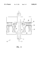
Referring to FIG. 1, there is a cross section of a typical related art rotatable single phase electromagnetic actuator 10. Actuator 10 has a shaft 12 with an axis 13, a stator 14, a rotor 16, and a bearing structure 25. The stator has a magnetic field inducing wire coil 18, a stator pole shoe 20, and a bearing support 24. Bearing assembly 25 includes a top and bottom bearing retaining housing 26, and a plurality of ball bearings 28. The rotor 16 includes a set of rotor magnets 22, also referred to as a rotor 22. It is noted that the actuator illustrates an ideal design, where the bearing parts, stator parts and rotor parts have all respective surfaces appropriately aligned either perpendicular or parallel.
3. Problem with the Related Art
A common problem occurring with the mounting of actuators is the inability to achieve exact alignment of the shaft between and the actuator the part to be controlled by the shaft. Specifically, actuators have not been designed to properly operate with a cantered or slanted shaft and still have low bearing wear. For example, FIG. 2a illustrates a related art problem typically encountered. Particularly, shaft 12 is misaligned, which causes a gap 41 and a reduced bearing gap 43 that places extreme bearing forces on the bearings in the reduced gap 43 section. Of course this problem will cause excessive wear on the bearing 25 and cause disastrous early failure of the whole actuator.
Another problem arises from manufacturing inefficiencies that create misaligned parts. The actuator requires precise alignment and dimensioning of all parts to avoid damaging misalignment problems. Referring to FIG. 2b, there is illustrated a typical misalignment problem. Namely, the left side of the bearing housing 26a is dimensionally wrong and the bearing support surface is spaced too far away. This misalignment places most of the bearing forces upon only one side of the bearing, which will cause the bearing to wear out prematurely.
Although the related art depicts certain problems, many problems are possible. For example, rotor surface 16, stator surface 14, and pole shoe surface 20 could all be out of specification tolerances, which would cause the bearing 25 to be misaligned. Additionally, although gap 41 is illustrated to be between the ball bearing 28 and bearing race 26, it is equally likely that the gap could be between any part of the bearing 25, rotor 16, and stator 14.
Therefore, there is a need for an actuator that is self aligning to allow for misalignment of actuator 10 parts that would create excessive bearing surface wear or ball bearing device 25 wear.
SUMMARY OF THE INVENTION
It is a feature of the invention to provide a motor and actuator. In particular, there is a rotatable single phase electromagnetic actuator that has a self aligning shaft that allows for misalignment of actuator parts that would lead to excessive bearing surface wearing.
An additional feature of the invention is to provide an actuator that allows for the cantering of the shaft relative to the actuator without creating excessive bearing surface wear or ball bearing device wear.
A further feature of the invention is to provide a bearing surface slanted or curved to allow the ball bearings to self align relative to the actuator body and still have a smooth bearing surface.
Yet, another feature of the invention is to provide an actuator that will operate when bearing race 26 and stator and/or rotor opposing surfaces do not align in an ideal parallel relationship.
Another feature of the invention is to provide an actuator that has a rotor, having a first rotor surface; a stator, having a slanted bearing surface opposed the first rotor surface; and a bearing device, mounted on and between the first rotor surface and the slanted bearing surface, positioned and shaped to separate the rotor from the stator and to self align on the slanted bearing surface in a position that substantially evenly distributes bearing loading on the bearing device.
The invention resides not in any one of these features per se, but rather in the particular combination of all of them herein disclosed and claimed. Those skilled in the art will appreciate that the conception, upon which this disclosure is based, may readily be utilized as a basis for the designing of other structures, methods and systems for carrying out the several purposes of the present invention. Further, the abstract is neither intended to define the invention of the application, which is measured by the claims, neither is it intended to be limiting as to the scope of the invention in any way.
BRIEF DESCRIPTION OF THE DRAWINGS
FIG. 1 is a cross sectional illustration of a related art actuator design.
FIG. 2a is a cross section of a portion of related art FIG. 1 having a slanted shaft.
FIG. 2b illustrates a typical misalignment of parts problem of FIG. 1.
FIG. 3 is a cross sectional side view of the preferred actuator embodiment.
FIG. 4 illustrates a cross sectional side view of another embodiment of a suitable bearing device.
FIG. 5 illustrates an operation of FIG. 4 with a cantered shaft and misaligned actuator parts.
It is noted that the drawings of the invention are not to scale. The drawings are merely schematic representations, not intended to portray specific parameters of the invention. The drawings are intended to depict only typical embodiments of the invention, and therefore should not be considered as limiting the scope of the invention. In the drawings, like numbering represents like elements between the drawings.
DETAILED DESCRIPTION OF THE PREFERRED EMBODIMENT
The present invention provides an electro-mechanical actuator. In particular, there is a rotatable single phase electromagnetic actuator that has a self aligning shaft that allows for misalignment of actuator parts that would lead to excessive bearing surface wearing. Regarding FIG. 3, there is a preferred embodiment of a novel actuator 10. In addition to the elements discussed in the prior figures, actuator 10 has a slanted bearing support 30 that is mounted, for space saving purposes, directly on wire coil winding 18 and stator 14 and is in physical contact therewith.
Referring to FIG. 4, there is a detailed cross sectional illustration of bearing device 25 from FIG. 3. Specifically, besides the prior elements described, wherein the bearing support 30 includes a groove 32, a bottom lip surface 34, a vertical back surface 35, a horizontal base surface 36, and an inclined or slanted surface 38, which has a preferred incline 37 that ranges from 5 to 45 degrees and preferably 15 degrees. Uniquely, the preferred invention has groove 32 mounted over and in contact with a corner of stator 14 bottom lip surface 34 is mounted onto and in contact with wire coil 18 for space saving purposes, vertical back surface 35 is in contact with pole shoe 20, and horizontal base surface 36 is contacting the stator 14. In addition, bearing 25 includes a top or upper race 42, a lower or bottom race 44, and a retainer 45 having an outer retainer feature 46, an inner retainer feature 48, and ball bearings 28. The retainer 45 with inner and outer retainer features 46 and 48 are also known in the art as a cage. Inner retainer feature 48 includes a lower race retainer portion 50 and ball bearing retainer portion 56. Outer retainer feature 46 includes an upper race retainer portion 52, and ball bearing retainer portion 54. Upper race 42 includes a ball bearing upper contact region 58, and an extended horizontal spacer section 64. Lower race 44 includes a ball bearing lower contact region 60 and a horizontal attachment section 62.
In operation, the stator 14 is typically fixed to a body of an object and the shaft 12 is coupled, on the stator side, to a device, like a valve, which is to be rotated. In a neutral position, permanent magnets 22 are opposing the stator pole shoes 20, there is a magnetic attraction therebetween, and there is no current passing through coil 18. To activate the actuator, current is passed through coil 18, thereby creating a magnetic polarity on the stator pole shoes 20 of either north or south, depending upon which way the coil is wound. Typically, the stator coils are wound to create a polarity that matches the opposing permanent magnets 22 to initially create unbalanced repulsive forces therebetween. These repulsive forces generate an axial rotational torque that will rotate about shaft 12.
Remarks About the Preferred Embodiment
One of ordinary skill in the art of designing and using actuators 10 will realize many advantages from studying and using the preferred embodiment. For example, referring to FIG. 5, there is illustrated an operation of FIG. 4 with a cantered shaft and misaligned or misdimensioned actuator parts. In particular, it is noted that shaft 12 is cantered to the right at the top, which shrinks the air gap on the right 70 and expands the air gap on the left 72. However, unlike the prior art, bearing device 25 remains in intimate contact with all required surfaces. The slanted surface 38 allows the bearing device 25 to self align by sliding into an equal bearing pressure position. Therefore, the actuator will function properly and the bearing device 25 will last longer with an even distribution of bearing pressure.
It is noted that the preferred embodiment design does not place the bearing surface 30 over the stator pole shoes 20. This allows for a tight fit of the bearing surface 30 because of groove 32 snugly fitting over a corner of stator 14.
One skilled in the art of bearing design will realize that both inner and outer retainer features 46 and 48 are circumferential in design, like a ring.
Variations of the Preferred Embodiment
Although the illustrated embodiments discuss the arrangement of an actuator motor, one skilled in the art will realize that the preferred embodiment would work with most any motor needing to have self aligning of the bearing device.
An additional variation of the invention contemplates the use of applying any type of bearing device 25 that can allow for proper rotation of the races while being mounted to a slanted surface 38.
A further variation of the preferred embodiment is that the slanted surface 30 can be positioned on the rotor 16 and still achieve the same self alignment benefits. In that case there would have to be a bearing flat surface on the stator side. A variation of this is to have two opposing slanted surfaces 30--one on the stator and one on the rotor.
While the invention has been taught with specific reference to these embodiments, someone skilled in the art will recognize that changes can be made in form and detail without departing from the spirit and the scope of the invention. The described embodiments are to be considered in all respects only as illustrative and not restrictive. The scope of the invention is, therefore, indicated by the appended claims rather than by the description. All changes that come within the meaning and range of equivalency of the claims are to be embraced within their scope.

Claims (14)

What is claimed and desired to be secured by United States patent is:
1. An actuator, comprising:
a) a rotor, having a first rotor surface;
b) a stator, having a bearing support member;
c) a slanted bearing surface, being part of the bearing support, member and opposed to the first rotor surface; and
d) a bearing device, mounted on and between the first rotor surface and the bearing support member, the bearing device having a lower race with a substantially arc shaped contact region directly contacting the slanted bearing surfaces, the bearing device positioned and shaped to separate the rotor from the stator and to self align on the slanted bearing surface in a position that substantially evenly distributes bearing loading on the bearing device.
2. The actuator of claim 1, further comprising a wire coil wrapped around the stator.
3. The actuator of claim 2, further comprising a stator magnetic shoe, mounted on the stator in opposing position to the first rotor surface, wherein the bearing support member has a vertical surface abutting to the stator magnetic shoe.
4. The actuator of claim 3, further comprising a shaft freely extending through the stator and securely extending into the rotor so that rotation of the rotor will cause rotation of the shaft.
5. The actuator of claim 2, wherein the slanted bearing surface is directly in contact with the wire coil.
6. A rotatable single phase electromagnetic actuator, comprising:
a) a stator;
b) a rotor;
c) a bearing device, mounted between the stator and rotor, for keeping opposing surfaces of the stator and rotor spaced apart; and
d) self alignment means, mounted between the stator and rotor and adjacent the bearing device, for self aligning the bearing device into a position that distributes bearing forces equally there around, the self alignment means including:
d1) a bearing support member, having a slanted surface, attached to the stator; and
d2) a lower race disposed on the bearing support member and having a substantially arc shaped contact region contacting the bearing support member such that any one point on the bearing device is prevented from having a higher bearing force than any other point thereon.
7. The actuator of claim 6, further comprising a wire coil wrapped around the stator.
8. The actuator of claim 7, further comprising a stator magnetic shoe, mounted on the stator in opposing position to the first rotor surface, wherein the bearing support member has a vertical surface abutting to the stator magnetic shoe.
9. The actuator of claim 8, further comprising a shaft freely extending through the stator and securely extending into the rotor so that rotation of the rotor will cause rotation of the shaft.
10. The actuator of claim 9, wherein the bearing support member has a slanted bearing surface circumferentially positioned around the shaft.
11. The actuator of claim 10, wherein the self alignment means is directly in contact with the wire coil.
12. An actuator, comprising:
a) a rotor, having a first rotor surface;
b) a stator, having a bearing support member;
c) a slanted bearing surface, being part of the bearing support, member and opposed to the first rotor surface; and
d) a bearing device, mounted on and between the first rotor surface and the bearing support member including:
d1) a lower race, attached to the bearing device, and having an arc shaped contact region directly contacting the slanted bearing surface such that the bearing device is aligned on the slanted bearing surface in a position that evenly distributes loading on the bearing device.
13. The actuator according to claim 12, wherein the slanted bearing surface is slanted with respect to the first rotor surface.
14. The actuator according to claim 12, further comprising a wire coil wrapped around the stator adjacent the bearing support member.
US08/919,013 1997-08-27 1997-08-27 Self aligning actuator with low bearing wear Expired - Lifetime US5828151A (en)

Priority Applications (3)

Application Number Priority Date Filing Date Title
US08/919,013 US5828151A (en) 1997-08-27 1997-08-27 Self aligning actuator with low bearing wear
CA002245038A CA2245038A1 (en) 1997-08-27 1998-08-14 A self aligning actuator with low bearing wear
EP98306834A EP0899854A3 (en) 1997-08-27 1998-08-26 A self aligning actuator with low bearing wear

Applications Claiming Priority (1)

Application Number Priority Date Filing Date Title
US08/919,013 US5828151A (en) 1997-08-27 1997-08-27 Self aligning actuator with low bearing wear

Publications (1)

Publication Number Publication Date
US5828151A true US5828151A (en) 1998-10-27

Family

ID=25441345

Family Applications (1)

Application Number Title Priority Date Filing Date
US08/919,013 Expired - Lifetime US5828151A (en) 1997-08-27 1997-08-27 Self aligning actuator with low bearing wear

Country Status (3)

Country Link
US (1) US5828151A (en)
EP (1) EP0899854A3 (en)
CA (1) CA2245038A1 (en)

Cited By (15)

* Cited by examiner, † Cited by third party
Publication number Priority date Publication date Assignee Title
US6196078B1 (en) 1999-01-11 2001-03-06 Grand Haven Stamped Products External electronic transmission shift system
US20030127926A1 (en) * 2002-01-09 2003-07-10 Sanyo Electric Co., Ltd. Motor device
US20050188798A1 (en) * 2004-02-26 2005-09-01 Bischof Kenneth R. Magnetically levitated high-speed spindle for shaping irregular surfaces
US20050248435A1 (en) * 2004-05-05 2005-11-10 Donald Robertson Lawrence Actuator with integral position sensor
US20060204160A1 (en) * 2005-03-14 2006-09-14 Northrop Grumman Corporation Self-aligning bearing assembly capable of reacting radial and axial loads
US20070008063A1 (en) * 2004-08-13 2007-01-11 Cts Corporation Rotary actuator with non-contacting position sensor
US20070058895A1 (en) * 2005-09-13 2007-03-15 Paschoalino Marcelo R Anti-friction thrust bearing centering device for hermetic refrigeration compressors
US20100060092A1 (en) * 2008-09-08 2010-03-11 Blakesley Patrick B Brushless direct current actuator
US20100301691A1 (en) * 2009-05-27 2010-12-02 Douglas Edward Cors Brushless Direct Current Actuator with Clip for Retaining Bobbins
US20110203769A1 (en) * 2010-02-24 2011-08-25 Douglas Edward Cors Cooling System for Actuator
US8450999B2 (en) 2009-02-17 2013-05-28 Cts Corporation Rotary position sensor
JP2014082846A (en) * 2012-10-15 2014-05-08 Asmo Co Ltd Motor
US20150054288A1 (en) * 2013-08-21 2015-02-26 Wolfhart Hans Willimczik Rotary Linear Generator (stroke-rotor generator)
US20160241107A1 (en) * 2015-02-10 2016-08-18 Yulanda YHW King Axial Brushless DC Motor
US10454403B2 (en) 2016-02-05 2019-10-22 Cts Corporation Axial brushless DC motor with fractional and hold step function

Citations (13)

* Cited by examiner, † Cited by third party
Publication number Priority date Publication date Assignee Title
US3749458A (en) * 1971-03-15 1973-07-31 Alfa Laval Ab Centering device for rotary shaft
US4541744A (en) * 1984-11-15 1985-09-17 General Motors Coporation Unitized bearing assembly with moldable race members and labryinth seal
US4645430A (en) * 1984-04-25 1987-02-24 Facet Enterprises, Inc. Wet motor gerotor fuel pump with self-aligning bearing
US4652152A (en) * 1982-03-13 1987-03-24 Skf Gmbh Self-aligning bearing
US4854437A (en) * 1986-06-25 1989-08-08 Aetna Bearing Company Radially adjustable clutch release bearing assembly
US4887919A (en) * 1985-01-08 1989-12-19 Skf (U.K) Limited Preventing movement of an article along a shaft or bore
US4951796A (en) * 1986-06-25 1990-08-28 Aetna Bearing Company Radially adjustable clutch release bearing assembly
US4973866A (en) * 1989-09-26 1990-11-27 North American Philips Corporation Variable angle stepper motor
US5054940A (en) * 1988-12-26 1991-10-08 Wing Highcera Co., Ltd. Ceramic bearing
US5110221A (en) * 1981-04-20 1992-05-05 Kamatics Corporation Self-aligning track roller
US5298825A (en) * 1989-06-16 1994-03-29 Moving Magnet Technologies Sa Single phase electro-magnetic actuator with low obstruction
US5334893A (en) * 1992-02-28 1994-08-02 Moving Magnet Technologies Sa Monophase electromagnetic rotary actuator of travel between 60 and 120 degrees
US5512871A (en) * 1990-12-17 1996-04-30 Moving Magnet Technologies S.A. Rotatable single-phase electromagnetic actuator

Family Cites Families (3)

* Cited by examiner, † Cited by third party
Publication number Priority date Publication date Assignee Title
FR2670629B1 (en) * 1990-12-17 1995-03-10 Moving Magnet Tech ROTARY SINGLE - PHASE ELECTROMAGNETIC ACTUATOR.
JP2566658Y2 (en) * 1992-10-09 1998-03-30 株式会社三協精機製作所 Motor bearing device
FR2744559B1 (en) * 1996-01-17 1998-04-10 Moving Magnet Tech SINGLE-PHASE ROTARY ELECTROMAGNETIC ACTUATOR WITH MAGNETIC SPRING AND ELECTRIC VALVE USING SUCH AN ACTUATOR

Patent Citations (13)

* Cited by examiner, † Cited by third party
Publication number Priority date Publication date Assignee Title
US3749458A (en) * 1971-03-15 1973-07-31 Alfa Laval Ab Centering device for rotary shaft
US5110221A (en) * 1981-04-20 1992-05-05 Kamatics Corporation Self-aligning track roller
US4652152A (en) * 1982-03-13 1987-03-24 Skf Gmbh Self-aligning bearing
US4645430A (en) * 1984-04-25 1987-02-24 Facet Enterprises, Inc. Wet motor gerotor fuel pump with self-aligning bearing
US4541744A (en) * 1984-11-15 1985-09-17 General Motors Coporation Unitized bearing assembly with moldable race members and labryinth seal
US4887919A (en) * 1985-01-08 1989-12-19 Skf (U.K) Limited Preventing movement of an article along a shaft or bore
US4854437A (en) * 1986-06-25 1989-08-08 Aetna Bearing Company Radially adjustable clutch release bearing assembly
US4951796A (en) * 1986-06-25 1990-08-28 Aetna Bearing Company Radially adjustable clutch release bearing assembly
US5054940A (en) * 1988-12-26 1991-10-08 Wing Highcera Co., Ltd. Ceramic bearing
US5298825A (en) * 1989-06-16 1994-03-29 Moving Magnet Technologies Sa Single phase electro-magnetic actuator with low obstruction
US4973866A (en) * 1989-09-26 1990-11-27 North American Philips Corporation Variable angle stepper motor
US5512871A (en) * 1990-12-17 1996-04-30 Moving Magnet Technologies S.A. Rotatable single-phase electromagnetic actuator
US5334893A (en) * 1992-02-28 1994-08-02 Moving Magnet Technologies Sa Monophase electromagnetic rotary actuator of travel between 60 and 120 degrees

Cited By (24)

* Cited by examiner, † Cited by third party
Publication number Priority date Publication date Assignee Title
US6196078B1 (en) 1999-01-11 2001-03-06 Grand Haven Stamped Products External electronic transmission shift system
US20030127926A1 (en) * 2002-01-09 2003-07-10 Sanyo Electric Co., Ltd. Motor device
US6828708B2 (en) * 2002-01-09 2004-12-07 Sanyo Electric Co., Ltd. Motor device including a thrust bearing having a thrust plate
US7264430B2 (en) 2004-02-26 2007-09-04 Federal Mogul World Wide, Inc Magnetically levitated high-speed spindle for shaping irregular surfaces
US20050188798A1 (en) * 2004-02-26 2005-09-01 Bischof Kenneth R. Magnetically levitated high-speed spindle for shaping irregular surfaces
US20050248435A1 (en) * 2004-05-05 2005-11-10 Donald Robertson Lawrence Actuator with integral position sensor
US7116210B2 (en) 2004-05-05 2006-10-03 Cts Corporation Actuator with integral position sensor
US20070008063A1 (en) * 2004-08-13 2007-01-11 Cts Corporation Rotary actuator with non-contacting position sensor
US20060204160A1 (en) * 2005-03-14 2006-09-14 Northrop Grumman Corporation Self-aligning bearing assembly capable of reacting radial and axial loads
US7293920B2 (en) 2005-03-14 2007-11-13 Northrop Grumman Corporation Self-aligning bearing assembly capable of reacting radial and axial loads
US20070058895A1 (en) * 2005-09-13 2007-03-15 Paschoalino Marcelo R Anti-friction thrust bearing centering device for hermetic refrigeration compressors
US20100060092A1 (en) * 2008-09-08 2010-03-11 Blakesley Patrick B Brushless direct current actuator
US8692544B2 (en) 2009-02-17 2014-04-08 Cts Corporation Rotary position sensor
US9297637B2 (en) 2009-02-17 2016-03-29 Cts Corporation Rotary position sensor
US8450999B2 (en) 2009-02-17 2013-05-28 Cts Corporation Rotary position sensor
US20100301691A1 (en) * 2009-05-27 2010-12-02 Douglas Edward Cors Brushless Direct Current Actuator with Clip for Retaining Bobbins
US8680727B2 (en) 2009-05-27 2014-03-25 Cts Corporation Brushless direct current actuator with clip for retaining bobbins
US20110203769A1 (en) * 2010-02-24 2011-08-25 Douglas Edward Cors Cooling System for Actuator
JP2014082846A (en) * 2012-10-15 2014-05-08 Asmo Co Ltd Motor
US20150054288A1 (en) * 2013-08-21 2015-02-26 Wolfhart Hans Willimczik Rotary Linear Generator (stroke-rotor generator)
US20160241107A1 (en) * 2015-02-10 2016-08-18 Yulanda YHW King Axial Brushless DC Motor
US10148152B2 (en) * 2015-02-10 2018-12-04 Cts Corporation Axial brushless DC motor
US10658902B2 (en) 2015-02-10 2020-05-19 Cts Corporation Axial brushless DC motor
US10454403B2 (en) 2016-02-05 2019-10-22 Cts Corporation Axial brushless DC motor with fractional and hold step function

Also Published As

Publication number Publication date
EP0899854A3 (en) 1999-11-24
CA2245038A1 (en) 1999-02-27
EP0899854A2 (en) 1999-03-03

Similar Documents

Publication Publication Date Title
US5828151A (en) Self aligning actuator with low bearing wear
JPH0720362B2 (en) Electric motor for hard disk drive
JPH0226215Y2 (en)
US5982058A (en) Two-phase stepper motor
JP2005127222A (en) Magnetic levitating pump
JP2004248492A (en) Seal construction for motor, motor, and motor for automatic transmission of automobile
EP1857695B1 (en) Ball bearing
US8269388B2 (en) Magnetic bearing assembly for rotors
US5445456A (en) Bearing assembly
EP1993188A2 (en) Electric motor
JPH0574301B2 (en)
EP3825563B1 (en) Magnetic bearing
US6362549B1 (en) Magnetic bearing device
US6299357B1 (en) Clutch bearing for automotive air conditioning compressor
JP4685227B2 (en) Magnetic levitation pump
JP3013264B2 (en) Magnetic levitation actuator
JPH04203520A (en) Thrust rolling bearing and roller and motor using thereof
JPS6399742A (en) Magnetic bearing integrating type motor
JP2584033Y2 (en) Thrust bearing device
JPH06261490A (en) Bearing unit for brushless motor
JP2000274392A (en) Pump
CN117480713A (en) Axial alignment system for a rotor of a rotating electrical machine and corresponding rotating electrical machine
JPH04337110A (en) Magnetic bearing
JPH0614087Y2 (en) Magnetic bearing device
JP2560848Y2 (en) Magnetic bearing device

Legal Events

Date Code Title Description
AS Assignment

Owner name: CTS CORPORATION, INDIANA

Free format text: ASSIGNMENT OF ASSIGNORS INTEREST;ASSIGNORS:BUSTAMANTE, ELEAZAR FELIPE;ADAMS, PHILLIP G.;HOSKIN, CATHERINE;AND OTHERS;REEL/FRAME:008685/0139

Effective date: 19970825

STCF Information on status: patent grant

Free format text: PATENTED CASE

FEPP Fee payment procedure

Free format text: PAYOR NUMBER ASSIGNED (ORIGINAL EVENT CODE: ASPN); ENTITY STATUS OF PATENT OWNER: LARGE ENTITY

FPAY Fee payment

Year of fee payment: 4

REMI Maintenance fee reminder mailed
FPAY Fee payment

Year of fee payment: 8

FPAY Fee payment

Year of fee payment: 12