US5832555A - Compact moveable ramp assembly - Google Patents
Compact moveable ramp assembly Download PDFInfo
- Publication number
- US5832555A US5832555A US08/804,816 US80481697A US5832555A US 5832555 A US5832555 A US 5832555A US 80481697 A US80481697 A US 80481697A US 5832555 A US5832555 A US 5832555A
- Authority
- US
- United States
- Prior art keywords
- platform
- ramp assembly
- mounting structure
- deployed
- top panel
- Prior art date
- Legal status (The legal status is an assumption and is not a legal conclusion. Google has not performed a legal analysis and makes no representation as to the accuracy of the status listed.)
- Expired - Lifetime
Links
Images


Classifications
-
- B—PERFORMING OPERATIONS; TRANSPORTING
- B60—VEHICLES IN GENERAL
- B60R—VEHICLES, VEHICLE FITTINGS, OR VEHICLE PARTS, NOT OTHERWISE PROVIDED FOR
- B60R3/00—Arrangements of steps or ladders facilitating access to or on the vehicle, e.g. running-boards
- B60R3/02—Retractable steps or ladders, e.g. movable under shock
-
- A—HUMAN NECESSITIES
- A61—MEDICAL OR VETERINARY SCIENCE; HYGIENE
- A61G—TRANSPORT, PERSONAL CONVEYANCES, OR ACCOMMODATION SPECIALLY ADAPTED FOR PATIENTS OR DISABLED PERSONS; OPERATING TABLES OR CHAIRS; CHAIRS FOR DENTISTRY; FUNERAL DEVICES
- A61G3/00—Ambulance aspects of vehicles; Vehicles with special provisions for transporting patients or disabled persons, or their personal conveyances, e.g. for facilitating access of, or for loading, wheelchairs
- A61G3/02—Loading or unloading personal conveyances; Facilitating access of patients or disabled persons to, or exit from, vehicles
- A61G3/06—Transfer using ramps, lifts or the like
- A61G3/061—Transfer using ramps, lifts or the like using ramps
-
- A—HUMAN NECESSITIES
- A61—MEDICAL OR VETERINARY SCIENCE; HYGIENE
- A61G—TRANSPORT, PERSONAL CONVEYANCES, OR ACCOMMODATION SPECIALLY ADAPTED FOR PATIENTS OR DISABLED PERSONS; OPERATING TABLES OR CHAIRS; CHAIRS FOR DENTISTRY; FUNERAL DEVICES
- A61G3/00—Ambulance aspects of vehicles; Vehicles with special provisions for transporting patients or disabled persons, or their personal conveyances, e.g. for facilitating access of, or for loading, wheelchairs
- A61G3/02—Loading or unloading personal conveyances; Facilitating access of patients or disabled persons to, or exit from, vehicles
- A61G3/06—Transfer using ramps, lifts or the like
- A61G3/067—Transfer using ramps, lifts or the like with compartment for horizontally storing the ramp or lift
-
- B—PERFORMING OPERATIONS; TRANSPORTING
- B60—VEHICLES IN GENERAL
- B60P—VEHICLES ADAPTED FOR LOAD TRANSPORTATION OR TO TRANSPORT, TO CARRY, OR TO COMPRISE SPECIAL LOADS OR OBJECTS
- B60P1/00—Vehicles predominantly for transporting loads and modified to facilitate loading, consolidating the load, or unloading
- B60P1/43—Vehicles predominantly for transporting loads and modified to facilitate loading, consolidating the load, or unloading using a loading ramp mounted on the vehicle
- B60P1/431—Vehicles predominantly for transporting loads and modified to facilitate loading, consolidating the load, or unloading using a loading ramp mounted on the vehicle the ramp being stored under the loading floor when not in use
-
- A—HUMAN NECESSITIES
- A61—MEDICAL OR VETERINARY SCIENCE; HYGIENE
- A61G—TRANSPORT, PERSONAL CONVEYANCES, OR ACCOMMODATION SPECIALLY ADAPTED FOR PATIENTS OR DISABLED PERSONS; OPERATING TABLES OR CHAIRS; CHAIRS FOR DENTISTRY; FUNERAL DEVICES
- A61G2220/00—Adaptations of particular transporting means
- A61G2220/16—Buses
-
- A—HUMAN NECESSITIES
- A61—MEDICAL OR VETERINARY SCIENCE; HYGIENE
- A61G—TRANSPORT, PERSONAL CONVEYANCES, OR ACCOMMODATION SPECIALLY ADAPTED FOR PATIENTS OR DISABLED PERSONS; OPERATING TABLES OR CHAIRS; CHAIRS FOR DENTISTRY; FUNERAL DEVICES
- A61G3/00—Ambulance aspects of vehicles; Vehicles with special provisions for transporting patients or disabled persons, or their personal conveyances, e.g. for facilitating access of, or for loading, wheelchairs
- A61G3/02—Loading or unloading personal conveyances; Facilitating access of patients or disabled persons to, or exit from, vehicles
- A61G3/06—Transfer using ramps, lifts or the like
-
- Y—GENERAL TAGGING OF NEW TECHNOLOGICAL DEVELOPMENTS; GENERAL TAGGING OF CROSS-SECTIONAL TECHNOLOGIES SPANNING OVER SEVERAL SECTIONS OF THE IPC; TECHNICAL SUBJECTS COVERED BY FORMER USPC CROSS-REFERENCE ART COLLECTIONS [XRACs] AND DIGESTS
- Y10—TECHNICAL SUBJECTS COVERED BY FORMER USPC
- Y10S—TECHNICAL SUBJECTS COVERED BY FORMER USPC CROSS-REFERENCE ART COLLECTIONS [XRACs] AND DIGESTS
- Y10S414/00—Material or article handling
- Y10S414/134—Handicapped person handling
Definitions
- This invention relates generally to ramps facilitating passengers to board and unload from vehicles, in particular, ramps facilitating access to persons with limited mobility.
- Ramps have also been developed for enabling access into and out of vehicles. As concerning ramps which travel with the vehicles, these ramps are typically stored in the vehicles when not in use and deployed when it is necessary to provide passenger access. When such a ramp is deployed, the two ends of the platform are typically positioned at different heights. One end is usually adjacent the vehicle floor and the other end is usually on the ground. As such, depending on the terrain on which the vehicles are parked, a relative height difference exists between the vehicle floor and the ground, which may be quite substantial.
- the ramp Since the passengers must travel across from one end of the ramp to the other, it is necessary that the ramp be fully deployable without obstruction by formations in the terrain. Also, when deployed, the ramp must provide a safe surface on which the passengers are supported while they travel across the ramp.
- Proposed wheelchair ramps have included a platform which is pivotally connected at a lower edge to the vehicle floor. Such a platform is typically stored in an upright position and is thus deployed by swinging the platform outwardly from the vehicle about the lower edge of the vehicle floor. Accordingly, the platform moves through a substantial range of motion with the upper edge starting from a relatively high position and ending at a relatively low position. With such a substantial range of motion, there exists a danger of undesirable motions or displacements in which the platform may move to undesirable positions, or even free fall through space. As a result, persons nearby may sustain injuries.
- wheelchair ramps have been designed to fit beneath the vehicle floor in which the platform translates from below the vehicle floor from a horizontal stored or stowed position to a deployed position where the platform extends beyond the vehicle to the ground surface.
- these ramps may avoid the dangers associated with the other proposed wheelchair ramps and are relatively less complex in design, they are often difficult to operate and do not easily fit below the vehicle floor surface.
- the ramps often cannot be fully deployed. For example, where the vehicles are parked curbside, the curb often obstructs the translating platform from reaching their full extension beyond the vehicles.
- a compact wheelchair ramp assembly (ramp assembly) is provided that can be securely stored beneath the vehicle floor.
- the ramp assembly is stored under the vehicle floor (or the operating passenger floor) and comprises a mounting structure having a series of top panels, a bottom panel, and side and cross beams positioned therebetween.
- the ramp assembly includes a moveable platform that deploys outward from the mounting structure forming an extended wheelchair ramp from ground level to the vehicle to allow passage into and out of the vehicle.
- the platform movement is facilitated by a motor unit positioned between the top and bottom panels of the mounting structure and a drive mechanism located above the platform but below the top panels.
- the wheelchair ramp assembly is compact enough so as to easily fit beneath the operating passenger floor of different vehicles.
- the ramp assembly is also designed so that it does not require full deployment of the platform to be functional, that is, the platform can be utilized in any stage of partial deployment.
- the platform has a pivotal connection which allows the free end of the platform to pivot downward if the platform does not reach the ground surface on full deployment. This allows the platform to be utilized for entry into the vehicle by persons occupying wheelchairs regardless of the distance between the vehicle and the curb. In addition, this acts as a safety feature which prevents someone from falling off the platform when inadvertently stepping on the platform.
- the ramp assembly also includes an interlock mechanism which locks the platform in place while the platform is in the stowed position.
- FIG. 1 is a diagrammatic representation of a front view of a vehicle carrying a ramp assembly in accordance with the present invention
- FIG. 2 is an exploded perspective view of a disclosed embodiment of the present ramp assembly
- FIG. 3 is a perspective view of a disclosed embodiment of the present ramp assembly without top panels with the ramp in the stowed position;
- FIG. 4 is a perspective view of the ramp assembly with the ramp in a deployed position
- FIGS. 5A-5D are diagrammatical representations of side elevation views of the disclosed embodiment of the present ramp assembly in various stages of deployment;
- FIG. 6 is a perspective view of the ramp assembly of FIG. 4 with top panels attached;
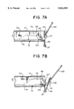
- FIGS. 7A-7C are side views of the pivoting door enclosure opened with a manual release bar
- FIG. 8 is a side view of the platform being manually removed from the ramp assembly.
- FIG. 9 is a diagrammatic representation of a front view of a vehicle with the platform pivoting downward due to force being exerted on the platform.
- a front portion of a vehicle V is shown carrying a wheelchair ramp assembly R fully extended on which a passenger in wheelchair (not shown) may travel from ground level to floor level F in the vehicle V.
- the vehicle with which the ramp assembly R may be used is not limited to buses and automobiles, as illustrated, but rather may include trailers, trains, etc. or any structure for transporting people.
- the ramp assembly R may be secured to the rear, side or other appropriate opening of a vehicle.
- the ramp assembly R is installed at the floor F of the vehicle V to operate through a side doorway (not shown).
- the ramp assembly R may be installed within the vehicle floor such that the passengers are supported directly on top of the ramp assembly R. That is, where the top panels of the ramp assembly R operate as the passenger floor.
- the ramp assembly R of one preferred embodiment is shown in an exploded view without the vehicle V.
- the ramp assembly R incorporates a platform 12, a mounting structure M having top panels 14, 24 and 26, a bottom panel 16 and side beams 18 and 20 rigidly affixed to bottom panel 16. Extending between the side beams 18 and 20, moving from the rear of the mounting structure M to the front, are cross beams 28, 30 and 32. The cross beams provide for added stability and structural support.
- the bottom panel 16 is affixed to the vehicle floor F by screws (not shown), or the like.
- the top panels 14, 24 and 26 operate as the passenger floor of the vehicle V in the disclosed embodiment.
- top panels 24 and 26 may be substituted by a larger single panel adjacent and coplanar with top panel 14 when the ramp assembly R is in the stowed position.
- FIG. 3 shows the ramp assembly R with the platform 12 in a stowed position with the top panels 14, 24 and 26 removed while FIG. 4 shows the ramp assembly R with the platform in a deployed position also with top panels 14, 24 and 26 removed.
- Platform 12 is movable relative to the mounting structure M.
- the platform 12 is movable between the top panels 14, 24 and 26 and the bottom panel 16 such that the platform 12 is stored between the top and bottom panels while it is in a stowed or stored position.
- the platform 12 When deployed, the platform 12 substantially extends beyond the outer edge 38 (See FIG. 3) of the ramp assembly R and projects from between the top and bottom panels 14 and 16 (see FIGS. 5A-5D).
- top panels 14, 24 and 26 of the mounting structure M are substantially planar and horizontal so as to function as the passenger floor.
- top panel 14 is pivotally connected to cross beam 32 by hinge 34 which allows top panel 14 to pivot up and down as the platform 12 moves through the mounting structure M. This can also be seen in FIGS. 5A-5D.
- top panel 14 inclines downward toward the platform 12 to serve as an extension of platform 12 to allow easy transition of a wheelchair from platform 12 to floor F of the vehicle, which in this case is comprised of top panels 24 and 26 (see FIG. 6).
- the outer edge 15 of top panel 14 is tapered downward to provide for a smooth transition from the platform 12 to the top panels 24 and 26.
- FIG. 6 shows the ramp assembly R with the platform 12 fully deployed with top panels 14, 24 and 26 attached.
- Cam guides 54 and 56 are shown in phantom inside side beams 18 and 20 respectively.
- a pair of rollers 48 may be affixed to the underside of top panel 14. As platform 12 is deployed, rollers 48 roll over the planar surface of platform 12 which prevents needless friction between the underside of panel 14 and platform 12 (see FIGS. 5A-5D). When platform 12 is in the stowed position, as shown in FIG. 5A, rollers 48 are positioned above platform 12 in an elevated position. The pair of rollers 48 are relatively small so that the outer edge 15 of top panel 14 pivots relatively close to platform 12 leaving little or no gap between outer edge 15 of top panel 14 and platform 12. This design significantly maximizes the actual usage of the ramp assembly R.
- rollers 48 While in the stowed position, rollers 48 are guided by a related pair of cams 73 and 75 located at projected end 13 against side edges 90 and 92. Cams 73 and 75 act to pivot rollers 48 and top panel 14 to the horizontal position coplanar with the vehicle floor.
- ramp assembly R has an interlock mechanism 140 which locks platform 12 inside the mounting structure M when the platform 12 is in the stowed position.
- Interlock mechanism 140 comprises a spring loaded pivoting pin 142 which is activated by solenoid 144. Both solenoid 144 and pin 142 are affixed to bracket 146 which is secured to bottom panel 16. The triangular stop 148 is fixed relative to platform 12. While in the stowed position (see FIG. 3), pin 142 abuts triangular stop 148 and prevents platform 12 from deploying. When the operator of the vehicle V activates a remote switch to deploy platform 12, solenoid 144 withdraws pin 142 thereby releasing triangular stop 148 and allowing platform 12 to deploy.
- pin 142 When platform 12 moves from the deployed to the stowed position, pin 142 is pushed inward by the hypotenuse side of triangular stop 148 as the platform moves to the stowed position. Once the pin 142 passes the hypotenuse side of triangular stop 148, pin 142 releases, thereby locking platform 12 into place. In the event that power to the vehicle V is lost, there is a manual release handle (not shown) which enables the release of interlock mechanism 140 to allow the platform 12 to deploy.
- the triangular stop 148 may be ultimately formed as a cam block or a rotary latch or the like to serve the same function.
- side beams 18 and 20 positioned below and extending the length of the lateral edges of the top panels 14, 24, 26 are side beams 18 and 20.
- the side beams 18 and 20 have inwardly facing surfaces 49 and 50 with channels defining cam guides 54 and 56.
- the cam guides 54 and 56 substantially extend the length of the side beams, ending at abutments 58 and 59 adjacent top panel 14 and ending at abutments 60 and 62 below top panel 24.
- the cam guides 54 and 56 guide the platform 12 as it moves between the stowed and the deployed positions. This will be explained later in greater detail.
- the bottom panel 16 is positioned below the side beams 18 and 20 and is substantially aligned with the top panels 14, 24 and 26.
- the bottom panel 16 is securely affixed to the side beams 18 and 20 by welding, screws (not shown) or the like.
- a rail alignment 72 is provided extending the length of the ramp assembly R.
- the rail alignment 72 is substantially centrally aligned between the side beams 18 and 20 and is fastened to the underneath surfaces of crossbeams 28, 30 and 32.
- the rail alignment 72 has an inverted T-shaped cross section with an upper track portion 74 supported on a base 76. Rail alignment 72 is coupled to the platform 12 such that it substantially aligns the platform 12 to the mounting structure M as the platform 12 moves between the stowed position and the deployed position.
- the platform 12 is divided between a fixed portion 79 and a pivotal portion 77.
- the fixed portion ' 79 side edges 91 and 93 and pivotal portion' 77 side edges 90 and 92 are turned upwardly as a safety feature to prevent passengers in wheelchairs from falling off the platform 12.
- Fixed portion' side edges 91 and 93 are tapered rearward of the platform 12 to form a pair of bracket arms 150 and 152 extending slightly beyond the fixed portion of the platform 12.
- the bracket arms 150 and 152 are each equipped with a pair of outwardly-facing cam followers 98 and 100.
- the cam followers 98 and 100 have dimensions enabling them to be received in the cam guides 54 and 56 of the side beams 18 and 20.
- cam guides 54 and 56 provide an upper track surface 55 and a lower track surface 57 defining a distance, for example, a height H, which is constant along most of the length of the cam guides 54 and 56.
- a height H which is constant along most of the length of the cam guides 54 and 56.
- cam follower 100 to track the upper track 55 and cam follower 98 to track the lower track 57 (see FIG. 5D) thereby causing bracket arms 150 and 152 and platform 12 to pivot downward toward the ground upon deployment.
- cam guides 54 and 56 at abutments 58 and 59, create a motion pattern for platform 12 which causes it to descend to the ground level upon deployment. This motion pattern is repeated in reverse when the platform moves from a deployed position to a stowed position.
- the compact design of the ramp assembly R is due to the fact that the motor unit 78 and drive mechanism 80 are contained within the mounting structure M between the bottom panel 16 and the top panels 14, 24 and 26.
- the motor unit 78 is positioned adjacent cross beam 28.
- Drive mechanism 80 in one embodiment, comprises ball screw 82 which is horizontally disposed and runs parallel to side beams 18 and 20.
- Belt 84 connects motor unit 78 to a pulley which in turn causes the ball screw 82 to rotate when the motor unit 78 is activated. Locating the drive mechanism 80 above the platform 12 and below the top panels 14, 24 and 26, as opposed to locating the drive mechanism below the platform 12 as with most ramp designs, provides a more compact ramp assembly R and enables the ramp assembly R to be stored beneath a vehicle floor.
- a block-alignment guide 94 Positioned to the side of alignment wheels 116 and 118 is a block-alignment guide 94 which is fastened to the alignment plate 88.
- Block-alignment guide 94 is adapted to receive ball screw 82, as shown in FIG. 4.
- Ball screw 82 rotates through block alignment guide 94 thereby facilitating movement of platform 12 through the mounting structure M.
- motor unit 78 which in turn rotates ball screw 82 thereby moving platform 12 through mounting structure M.
- the motor unit 78 can be operated from a remote switch located near the operator of the vehicle or by the operator using a remote control device. This provides the operator of the vehicle the ability to operate the ramp assembly R from a remote location.
- the drive mechanism 80 is not limited to the ball screw design coupled to a motor unit but may include a chain and sprocket mechanism, hydraulics or any other means for facilitating movement of the platform 12.
- the ramp assembly R may be manually operated. If, for example, the vehicle V loses power, the ramp assembly R may still be utilized.
- the ramp assembly R has a pivoting door enclosure 96 which is pivotally connected to the mounting structure M by hinges 97.
- the pivoting door enclosure 96 is spring activated by spring mechanism 101 which maintains pivoting door enclosure 96 in the closed position.
- hook 103 is coupled to nodule 107 which additionally secures pivoting door enclosure 96.
- the pivoting door enclosure 96 has on its outer surface a clip 113 for receiving the tapered end 102 of manual release bar 100. By inserting the tapered end 102 of manual release bar 100 into clip 113 and applying downward force, the pivoting door enclosure 96 may be opened (see FIGS. 7A-7C).
- Pivotal portion 77 of platform 12 has a slot 106 defined in its outer edge 13 for receiving the curved end 104 of the manual release bar 100.
- the manual release bar 100 By inserting the manual release bar 100 in slot 106 and rotating the manual release bar 100 counter clockwise as shown in FIG. 8., the manual release bar securely locks into slot 106.
- the platform 12 By pulling the manual release bar 100 outward from the ramp assembly R, the platform 12 may be deployed (see FIG. 8). Likewise, for manually storing the platform 12, these steps are performed in reverse order.
- platform 12 is shown in the stowed position (FIG. 5A), in partially deployed positions (FIGS. 5B-5C) and in the fully deployed position (FIG. 5D).
- platform 12 In the stowed position (FIG. 5A), platform 12 is positioned substantially between the top panels 14, 24 and 26 and the bottom panel 16. In the deployed position, the platform 12 extends substantially beyond the outer edge 38 (see FIG. 3) of the mounting structure M.
- the platform 12 is deployed through a motion pattern which is substantially straight out (FIGS. 5A-5B) followed by a downwardly inclined motion (FIGS. 5C-5D). Accordingly, as the cam followers 98 and 100 travel through the cam guides 54 and 56, the platform 12 substantially translates horizontally across and through the mounting structure M.
- top panel 14 While the platform 12 is in the stowed position, top panel 14 is supported by the platform 12 in a substantially horizontal position. Thus, when the platform 12 is in the stowed position, the top panel 14 is substantially even with the top panels 24 and 26, functioning as a part of the passenger floor.
- the ramp assembly R When platform 12 is fully deployed, the ramp assembly R provides an extended surface on which the passengers may travel from the sidewalk or ground surface to inside the vehicle or vice versa.
- the extended surface is a combination of the platform 12 and the top panel 14 which is also positioned in a downwardly incline, bridging any gap between top panel 14 and the platform 12. Equipped with the hinged platform 12, the vehicle V can safely and reliably load and unload passengers in wheelchairs from the vehicle V to a sidewalk 26 (see FIG. 1).
- the ramp assembly R does not require full deployment for operation.
- the ramp assembly R is operational for use by wheelchairs when the platform 12 is either partially or fully deployed.
- the ramp assembly R is operational when the platform 12 is either partially or fully deployed, the vehicle V can be close to or far from the curb wall 34 when deploying platform 12. This allows the operator of the vehicle V greater flexibility in positioning the vehicle adjacent to the curb wall 34 (see FIG. 1).
- the platform 12 is divided into a fixed portion 79 and a pivotal portion 77.
- the two portions are connected by a hinge 114 which pivotally connects the fixed portion 79 and the pivotal portion 77.
- hinge 114 runs the entire width of the connected platform 12.
- Adjacent the outer upturned edges 90 and 92 on the free end 13 of platform 12, a pair of compression springs 120 and 121 are coupled to housings 122 and 124, which are affixed to the outer upturned edges 90 and 92 respectively, of platform 12.
- the compression springs 120 and 121 are linearly coupled to a pair of strap bolts 126 and 128 which run adjacent and parallel to upturned edges 90 and 92.
- the strap bolts 126 and 128 are attached at their first ends 130 and 132 to compression springs 120 and 121. Strap bolts 126 and 128 are pivotally attached at their second ends 138 and 140 to fixed portion 79 of platform 12 at pivot points 134 and 136 located in the upturned side edges 90 and 92 of fixed portion 79 of platform 12.
- the pivot points 134 and 136 are comprised of a bolt shoulder with circular openings for receiving a bolt (not shown).
- This spring arrangement keeps pivotal portion 77 of platform 12 coplanar with fixed portion 79 of platform 12 when the platform is deployed. However, as shown in FIG. 9, if a downward force is applied to pivotal portion 77 of platform 12, the pivotal portion 77 pivots downward to the ground surface. When the downward force is removed, the pivotal portion 77 will return to coplanar alignment with fixed portion 79 due to compression springs 120 and 121, which constantly exert an upward force on pivotal portion 77 of platform 12.
- the hinged platform 12 enables the ramp assembly R to accommodate most terrain, especially that of a curbside where the sidewalk is relatively high compared to an adjacent gutter. Where a vehicle utilizing the ramp assembly R to enable passengers in wheelchairs to board and exit the vehicle, the ramp assembly R is safely and reliably deployed over the curb to rest atop the sidewalk without hitting the curb wall 34.
- the ramp assembly R is well suited for a vehicle suspended low to the ground and/or having a low vehicle floor.
- a sensor 110 is located between crossbeams 28 and 30 adjacent side beam 18 for sensing the presence of platform 12 while in the stowed position.
- the sensor 110 can be operatively connected to a warning light located near the operator of the vehicle V to indicate to the vehicle V operator when the platform 12 deployed. This would indicate to the vehicle V operator that the platform 12 is deployed to prevent the operator from driving the vehicle while the platform 12 is still in the deployed position.
- the sensor could be connected to a main power circuit of the vehicle V, sending a control signal to the main power circuit when the platform 12 is in the fully stowed position allowing the main power circuit to be turned on or off. It can also indicate a control signal to disable the main power circuit when the platform is in the deployed position thereby preventing the vehicle V operator from driving the vehicle if the platform 12 is in the deployed position.
- sensors 112 may be installed at the free end of the platform 12 for sensing objects, such as people, which may obstruct the movement of the platform 12, or be injured by the platform 12 (see FIGS. 4 and 6). Both sensors 110 and 112 may be a contact, magnetic or visual sensor or another type of sensor which can detect such objects.
- the system of the present invention may be readily incorporated in various embodiments to provide an improved ramp assembly.
- the various components and dimensions disclosed herein are merely exemplary, and of course, various alternative techniques may be employed departing from those disclosed and suggested herein.
- the cam guides and the cam followers may be replaced by other structures, such as kinematic structures, for moving the platform relative to the mounting structure.
- other driving members may be employed to motorize the present ramp. Consequently, it is to be understood that the scope hereof should be determined in accordance with the claims as set forth below.
Abstract
Description
Claims (25)
Priority Applications (7)
| Application Number | Priority Date | Filing Date | Title |
|---|---|---|---|
| US08/804,816 US5832555A (en) | 1995-02-27 | 1997-02-24 | Compact moveable ramp assembly |
| PCT/US1997/009133 WO1998036723A1 (en) | 1997-02-24 | 1997-05-13 | A moveable ramp assembly |
| AU31475/97A AU3147597A (en) | 1997-02-24 | 1997-05-13 | A moveable ramp assembly |
| JP18489997A JP3156996B2 (en) | 1997-02-24 | 1997-07-10 | Compact type movable ramp assembly |
| CA002229680A CA2229680C (en) | 1997-02-24 | 1998-02-16 | A moveable ramp assembly |
| AU54672/98A AU716015B2 (en) | 1997-02-24 | 1998-02-16 | A compact moveable ramp assembly |
| GB9803900A GB2322353B (en) | 1997-02-24 | 1998-02-24 | Ramp assemblies |
Applications Claiming Priority (2)
| Application Number | Priority Date | Filing Date | Title |
|---|---|---|---|
| US08/395,556 US5636399A (en) | 1995-02-27 | 1995-02-27 | Movable ramp assembly |
| US08/804,816 US5832555A (en) | 1995-02-27 | 1997-02-24 | Compact moveable ramp assembly |
Related Parent Applications (1)
| Application Number | Title | Priority Date | Filing Date |
|---|---|---|---|
| US08/395,556 Continuation-In-Part US5636399A (en) | 1995-02-27 | 1995-02-27 | Movable ramp assembly |
Publications (1)
| Publication Number | Publication Date |
|---|---|
| US5832555A true US5832555A (en) | 1998-11-10 |
Family
ID=25189919
Family Applications (1)
| Application Number | Title | Priority Date | Filing Date |
|---|---|---|---|
| US08/804,816 Expired - Lifetime US5832555A (en) | 1995-02-27 | 1997-02-24 | Compact moveable ramp assembly |
Country Status (6)
| Country | Link |
|---|---|
| US (1) | US5832555A (en) |
| JP (1) | JP3156996B2 (en) |
| AU (2) | AU3147597A (en) |
| CA (1) | CA2229680C (en) |
| GB (1) | GB2322353B (en) |
| WO (1) | WO1998036723A1 (en) |
Cited By (66)
| Publication number | Priority date | Publication date | Assignee | Title |
|---|---|---|---|---|
| US6010298A (en) * | 1998-04-15 | 2000-01-04 | Lift-U Division Of Hogan Mfg., Inc. | Low floor vehicle ramp assembly |
| US6131225A (en) * | 1997-04-15 | 2000-10-17 | Otis Elevator Company | Docking assembly for a shuttle |
| US6186733B1 (en) * | 1998-04-15 | 2001-02-13 | Lift-U, Division Of Hogan Mfg., Inc. | Low floor vehicle ramp assembly |
| WO2001021434A2 (en) * | 1999-09-22 | 2001-03-29 | Fine Products, S.A. | Access ramp for individuals with reduced mobility |
| US6264416B1 (en) | 2000-03-09 | 2001-07-24 | Vantage Mobility International, Llc | Compact, slide-out ramp for a minivan |
| EP1121920A2 (en) * | 2000-01-31 | 2001-08-08 | S.A. Masats | Retractable ramp suitable for motor vehicles |
| US6340280B1 (en) * | 1998-05-20 | 2002-01-22 | Universal City Studios, Inc. | Amusement ride vehicle with wheelchair ramp |
| WO2002055334A1 (en) * | 2001-01-09 | 2002-07-18 | Truck-Align Co., Ltd. | Ramp assembly |
| US6435804B1 (en) | 1999-05-19 | 2002-08-20 | Mark Hutchins | Lifting apparatus |
| US6481037B1 (en) | 1998-04-14 | 2002-11-19 | Trans-Ramp Pty Ltd | Articulated ramp assembly |
| US6484344B1 (en) * | 2001-08-10 | 2002-11-26 | Simon M. Cooper | Retractable access ramp |
| US6598253B1 (en) * | 1998-10-05 | 2003-07-29 | Robert John Allen | Extendable ramp assembly for detecting an obstruction and responding thereto |
| US20040013507A1 (en) * | 2001-08-22 | 2004-01-22 | Aaron Kiser | Wheelchair ramp with side barriers |
| US20040022613A1 (en) * | 2002-07-30 | 2004-02-05 | Overhead Door Corporation | Folding ramp |
| US6688835B1 (en) | 2001-07-25 | 2004-02-10 | James W. DeCaro | Side ramp assembly for a trailer |
| US6802095B1 (en) * | 2002-01-25 | 2004-10-12 | Ricon Corporation | Ramp assembly having a lift and lock mechanism |
| KR100466446B1 (en) * | 2001-11-19 | 2005-01-15 | 학림공업 주식회사 | Wheel chair up and down assembly of vehicles |
| US20050215371A1 (en) * | 2001-01-26 | 2005-09-29 | The Braun Corporation | Drive mechanism for a vehicle access system |
| US20060182578A1 (en) * | 2005-01-26 | 2006-08-17 | Escalera, Inc. | Cart & dual use ramp for console copier relocation |
| US20060245883A1 (en) * | 2005-04-11 | 2006-11-02 | Yves Fontaine | Vehicle ramp assembly |
| US7228582B1 (en) * | 2004-06-17 | 2007-06-12 | Pro-Ramp Electric, Llc | Extendable ramp for boats and vehicles |
| US20070176453A1 (en) * | 2006-02-02 | 2007-08-02 | Georgetown Rail Equipment Company | Rail car having extendable ramp being movable by a load bearing drive system |
| US20070183880A1 (en) * | 2006-02-03 | 2007-08-09 | Ricon Corp. | Slidably collapsible two arm wheel chair lift |
| US20070183881A1 (en) * | 2006-02-03 | 2007-08-09 | Ricon Corp. | Wheelchair lift with slidable support arm |
| US20080028546A1 (en) * | 2004-05-10 | 2008-02-07 | Kevin John Fullerton | Bridging Device |
| US20080042114A1 (en) * | 2004-11-30 | 2008-02-21 | Joseph Stanislao | Lift apparatus with telescoping platform attachment and method |
| US20090106918A1 (en) * | 2007-10-30 | 2009-04-30 | Marshall Elevator Company | Retractable Ramp |
| US7527467B2 (en) * | 2003-01-29 | 2009-05-05 | The Braun Corporation | Retractable ramp system for a mobility vehicle |
| US20090274542A1 (en) * | 2005-11-08 | 2009-11-05 | Pocobello Michael A | Automotive vehicle having a power-actuated ramp |
| US20090277725A1 (en) * | 2006-12-19 | 2009-11-12 | Kone Corporation | Elevator arrangement |
| US20100050564A1 (en) * | 2008-08-29 | 2010-03-04 | F3 And I2, Llc | Enclosure undercarriage support system |
| US7726446B1 (en) * | 2005-01-28 | 2010-06-01 | Vernon Roger Buchanan | Mobile hunting blind |
| US20110027054A1 (en) * | 2009-07-28 | 2011-02-03 | Eric Hansen | Front entry power access ramp |
| US20110023245A1 (en) * | 2008-04-07 | 2011-02-03 | Magna Car Top Systems Gmbh | Articulated loading ramp |
| US20110088178A1 (en) * | 2009-10-15 | 2011-04-21 | Yves Fontaine | Deployable ramp assembly |
| DE202012000642U1 (en) | 2012-01-23 | 2012-02-27 | Policske Strojirny A.S. | Entry lift for means of transport with lateral driveway for a wheelchair |
| KR101157563B1 (en) * | 2010-07-23 | 2012-06-18 | 대우버스(주) | Ramp for the wheelchair in the bus |
| EP2810632A1 (en) * | 2013-06-05 | 2014-12-10 | Vehixel Carrossier Constructeur | Vehicle access ramp |
| US9126522B1 (en) * | 2014-01-31 | 2015-09-08 | Vantage Mobility International, Llc | In-floor vehicle ramp |
| US20160177541A1 (en) * | 2013-08-22 | 2016-06-23 | Caterpillar Sarl | Catwalk of Construction Machine |
| USD768950S1 (en) * | 2014-07-07 | 2016-10-11 | Gumboots Nominees Pty Limited | Platform shuttle |
| US20170036872A1 (en) * | 2015-08-07 | 2017-02-09 | Ford Global Technologies, Llc | Powered Sliding Platform Assembly |
| CN107720326A (en) * | 2017-10-31 | 2018-02-23 | 禹州市硕宇机械配件有限公司 | A kind of automobile easing gear |
| CN108674317A (en) * | 2018-06-08 | 2018-10-19 | 利谙简工业技术(南京)有限公司 | A kind of scalable wheelchair access mechanism |
| US10106069B2 (en) * | 2014-11-28 | 2018-10-23 | Gebr. Bode Gmbh & Co. Kg | Retractable step having a lifting and ramp function |
| WO2019017845A1 (en) * | 2017-07-20 | 2019-01-24 | Nicae (Singapore) Pte Ltd | Automatic ramp |
| CN109512589A (en) * | 2018-12-29 | 2019-03-26 | 利谙简工业技术(南京)有限公司 | The scalable wheelchair access mechanism of vehicle mounted electric |
| US20190106042A1 (en) * | 2017-10-09 | 2019-04-11 | The Braun Corporation | Ramp assembly for motorized vehicle |
| US10266233B2 (en) * | 2016-03-30 | 2019-04-23 | Robert M. Dishon | Ramp assembly systems and methods of use |
| US10280637B2 (en) * | 2014-01-16 | 2019-05-07 | Gumboots Moninee Pty Limited | Load carrying platform shuttle |
| US10493893B2 (en) * | 2017-12-26 | 2019-12-03 | Toyota Jidosha Kabushiki Kaisha | Electrically-driven vehicle |
| US10702064B1 (en) * | 2017-06-12 | 2020-07-07 | Mobility Transfer Experts, LLC | Mobile platform and related methods |
| US10835832B2 (en) | 2019-03-31 | 2020-11-17 | Universal City Studio LLC | Gap covering systems and methods for amusement park attractions |
| WO2021003216A1 (en) * | 2019-07-03 | 2021-01-07 | The Braun Corporation | Ramp assembly with raised ramp position |
| US11007918B2 (en) * | 2019-06-03 | 2021-05-18 | Aisin Keikinzoku Co., Ltd. | Ramp apparatus for vehicle |
| US11034275B1 (en) * | 2019-10-23 | 2021-06-15 | Clarence Smith | System for a stowable vehicle ramp |
| IT202000009148A1 (en) * | 2020-04-27 | 2021-10-27 | Ferri Srl | REMOTE CONTROL VEHICLE WITH SUPPORT AND TRANSPORT DEVICE FOR ONE OPERATOR |
| US20210361499A1 (en) * | 2018-03-21 | 2021-11-25 | Masats, S.A. | Retractable ramp assembly for allowing people to enter vehicles |
| WO2022016218A1 (en) * | 2020-07-22 | 2022-01-27 | Mircea Eugen Virgil Cociuban The Trustee For Rofraus Trust | Descending mechanised access ramp (d-mar) |
| US20220219589A1 (en) * | 2021-01-13 | 2022-07-14 | Toyota Jidosha Kabushiki Kaisha | Vehicle equipped with slope device |
| US11465544B2 (en) * | 2019-01-11 | 2022-10-11 | Toyota Jidosha Kabushiki Kaisha | Vehicle |
| US20220410783A1 (en) * | 2021-06-25 | 2022-12-29 | Hyundai Motor Company | Ramp system of vehicle |
| DE10392237B4 (en) | 2002-01-25 | 2023-03-02 | Ricon Corp. | Ramp assembly with a lifting and locking mechanism |
| US11660239B2 (en) * | 2018-10-05 | 2023-05-30 | Transdev Group Innovation | Electronic device for controlling an access ramp to vehicle door, vehicle, steering method and computer program therefor |
| US11834838B2 (en) | 2019-05-06 | 2023-12-05 | Richard Hoffberg | Wheelchair ramp |
| US11919361B2 (en) | 2022-03-21 | 2024-03-05 | Ford Global Technologies, Llc | Vehicle floor panel |
Families Citing this family (16)
| Publication number | Priority date | Publication date | Assignee | Title |
|---|---|---|---|---|
| US6102648A (en) * | 1997-09-05 | 2000-08-15 | Ricon Corporation | Driving mechanism for vehicle lifts |
| AU739489B2 (en) * | 1998-04-14 | 2001-10-11 | Trans-Ramp Pty Ltd | Articulated ramp assembly |
| EP1078813A3 (en) * | 1999-08-27 | 2004-02-18 | Giovanni Lanza | Device for accessing a load platform in a vehicle |
| GB2356617B (en) * | 1999-10-05 | 2003-12-10 | Manganese Bronze Components Lt | Ramp assembly |
| KR100569189B1 (en) * | 2004-04-28 | 2006-04-07 | 현대자동차주식회사 | Sliding Ramp Operating Apparatus of Bus |
| FR2887504B1 (en) * | 2005-06-28 | 2008-08-08 | Metalic Sarl | RETRACTABLE RAMP FOR ACCESS TO A VEHICLE, PUBLIC TRANSPORT VEHICLE IN PARTICULAR |
| GB2455764A (en) * | 2007-12-20 | 2009-06-24 | Truck Align Company Ltd | Manually-deployable access ramp assembly |
| KR101048476B1 (en) * | 2008-10-31 | 2011-07-11 | 주식회사 지앤디윈텍 | Sliding lamp |
| ITRM20110324A1 (en) * | 2011-06-22 | 2012-12-23 | Sist Guida 2000 S R L | TIE-ROD / PUNCH DEVICE FOR TIPPED RAMPS, IN PARTICULAR RAMPS FOR THREE-WHEEL MOTORCYCLES. |
| US9101519B2 (en) | 2013-02-07 | 2015-08-11 | Dallas Smith Corporation | Leveling ramp for a wheelchair |
| CN103481831B (en) * | 2013-07-11 | 2015-08-12 | 江苏捷诚车载电子信息工程有限公司 | Vehicle mounted electric scaling platform |
| CN106080362B (en) * | 2016-08-20 | 2018-09-28 | 国网山东省电力公司龙口市供电公司 | A kind of Phase of Electric Power Projects emergency car |
| KR102104278B1 (en) * | 2018-07-25 | 2020-04-24 | 경북보건대학교 산학협력단 | Bus equipped with convenience for the old and the infirm |
| CN110406448A (en) * | 2019-08-13 | 2019-11-05 | 江西长淮汽车有限公司 | A kind of trailer device for discharging with preventing dust function |
| DE202020105492U1 (en) * | 2020-09-25 | 2022-01-07 | Gebr. Bode Gmbh & Co. Kg | Boarding device for a vehicle |
| EP4177128A1 (en) * | 2021-11-09 | 2023-05-10 | Stadler Rail AG | Access assembly for the entrance to a vehicle, vehicle comprising an access assembly and method for bridging a horizontal and / or vertical distance between a vehicle and a walkway or platform |
Citations (24)
| Publication number | Priority date | Publication date | Assignee | Title |
|---|---|---|---|---|
| US4325668A (en) * | 1978-09-18 | 1982-04-20 | Pinetree Service Corporation | Powered platform lift system for persons in wheelchairs |
| US4339224A (en) * | 1980-09-08 | 1982-07-13 | Lamb Charles A | Apparatus for accommodating wheelchairs in public transportation vehicles |
| AT374154B (en) * | 1980-04-28 | 1984-03-26 | Steyr Daimler Puch Ag | ACCESS RAMP ON A MOTOR VEHICLE, IN PARTICULAR AUTOBUS |
| US4466771A (en) * | 1981-05-29 | 1984-08-21 | Thorley Graham R | Wheelchair lift |
| EP0217265A1 (en) * | 1985-09-25 | 1987-04-08 | Gec Alsthom Sa | Device for easy access to railway vehicles during station stops |
| US4685857A (en) * | 1985-11-25 | 1987-08-11 | Goeser Maurice N | Vehicle load-carrying apparatus |
| US4685858A (en) * | 1986-02-20 | 1987-08-11 | Transpec Inc. | Vehicle entrance ramp |
| US4759682A (en) * | 1987-05-06 | 1988-07-26 | Transpec Inc. | Vehicle entrance ramp |
| US4827548A (en) * | 1988-05-23 | 1989-05-09 | Transpec Inc. | Vehicle entrance ramp |
| US4845792A (en) * | 1988-04-27 | 1989-07-11 | Snap-On Tools Corporation | Two-part adjustable approach ramp |
| US4850788A (en) * | 1987-07-13 | 1989-07-25 | Dickson Industries, Inc. | Ramp assembly for trailers and the like |
| US5160236A (en) * | 1991-07-31 | 1992-11-03 | Redding Edward M | Retractable van side door ramp |
| DE4234064A1 (en) * | 1991-10-15 | 1993-05-13 | Richard Schminke | Ramp surface for loading/unloading transport vehicles - has movable platform driven by hydraulic cylinders which can draw in supporting tongues against spring pressure |
| US5257894A (en) * | 1992-04-23 | 1993-11-02 | Grant Howard K | Small vehicle stowable ramp system |
| US5259081A (en) * | 1991-02-19 | 1993-11-09 | James Henderson | Portable wheel chair ramp and restraining device |
| EP0578574A1 (en) * | 1992-07-10 | 1994-01-12 | Gec Alsthom Transport Sa | Improved access device for a rail vehicle |
| US5284414A (en) * | 1991-05-15 | 1994-02-08 | Hogan Mfg., Inc. | Wheelchair lift with linkage assembly and hinged connection joint |
| US5299904A (en) * | 1992-03-26 | 1994-04-05 | Hogan Mfg., Inc. | Vehicle lift with contact sensor |
| US5305486A (en) * | 1993-06-24 | 1994-04-26 | Wheelers Manufacturing, Inc. | Vehicle passenger boarding system |
| US5380144A (en) * | 1993-09-10 | 1995-01-10 | Care Concepts, Inc. | Deployable vehicle access ramp |
| US5391041A (en) * | 1993-01-06 | 1995-02-21 | New Flyer Industries Limited | Hydraulically operated bus ramp mechanism |
| US5393192A (en) * | 1993-10-01 | 1995-02-28 | Reb Manufacturing Co., Inc. | Underfloor extendible ramp for vehicles |
| US5636399A (en) * | 1995-02-27 | 1997-06-10 | Ricon Corporation | Movable ramp assembly |
| US5675515A (en) * | 1995-12-28 | 1997-10-07 | Hunter Engineering Company | Apparatus and method for determining vehicle wheel alignment measurements from three dimensional wheel positions and orientations |
Family Cites Families (3)
| Publication number | Priority date | Publication date | Assignee | Title |
|---|---|---|---|---|
| US4624619A (en) * | 1984-09-04 | 1986-11-25 | Uher Michael L | Retractable ramp assembly for pick-up truck |
| US4900217A (en) * | 1988-07-15 | 1990-02-13 | Nelson Jon N | Stowable, multiple grade ramping device |
| US5331701A (en) * | 1993-09-13 | 1994-07-26 | Chase Vearl J | Vehicle chair ramp apparatus |
-
1997
- 1997-02-24 US US08/804,816 patent/US5832555A/en not_active Expired - Lifetime
- 1997-05-13 WO PCT/US1997/009133 patent/WO1998036723A1/en active Application Filing
- 1997-05-13 AU AU31475/97A patent/AU3147597A/en not_active Abandoned
- 1997-07-10 JP JP18489997A patent/JP3156996B2/en not_active Expired - Lifetime
-
1998
- 1998-02-16 AU AU54672/98A patent/AU716015B2/en not_active Expired
- 1998-02-16 CA CA002229680A patent/CA2229680C/en not_active Expired - Lifetime
- 1998-02-24 GB GB9803900A patent/GB2322353B/en not_active Expired - Lifetime
Patent Citations (26)
| Publication number | Priority date | Publication date | Assignee | Title |
|---|---|---|---|---|
| US4325668A (en) * | 1978-09-18 | 1982-04-20 | Pinetree Service Corporation | Powered platform lift system for persons in wheelchairs |
| AT374154B (en) * | 1980-04-28 | 1984-03-26 | Steyr Daimler Puch Ag | ACCESS RAMP ON A MOTOR VEHICLE, IN PARTICULAR AUTOBUS |
| US4339224A (en) * | 1980-09-08 | 1982-07-13 | Lamb Charles A | Apparatus for accommodating wheelchairs in public transportation vehicles |
| US4466771A (en) * | 1981-05-29 | 1984-08-21 | Thorley Graham R | Wheelchair lift |
| EP0217265A1 (en) * | 1985-09-25 | 1987-04-08 | Gec Alsthom Sa | Device for easy access to railway vehicles during station stops |
| US4685857A (en) * | 1985-11-25 | 1987-08-11 | Goeser Maurice N | Vehicle load-carrying apparatus |
| US4685858A (en) * | 1986-02-20 | 1987-08-11 | Transpec Inc. | Vehicle entrance ramp |
| US4759682A (en) * | 1987-05-06 | 1988-07-26 | Transpec Inc. | Vehicle entrance ramp |
| US4850788A (en) * | 1987-07-13 | 1989-07-25 | Dickson Industries, Inc. | Ramp assembly for trailers and the like |
| US4845792A (en) * | 1988-04-27 | 1989-07-11 | Snap-On Tools Corporation | Two-part adjustable approach ramp |
| US4827548A (en) * | 1988-05-23 | 1989-05-09 | Transpec Inc. | Vehicle entrance ramp |
| US5259081A (en) * | 1991-02-19 | 1993-11-09 | James Henderson | Portable wheel chair ramp and restraining device |
| US5284414A (en) * | 1991-05-15 | 1994-02-08 | Hogan Mfg., Inc. | Wheelchair lift with linkage assembly and hinged connection joint |
| US5433580A (en) * | 1991-05-15 | 1995-07-18 | Hogan Mfg., Inc. | Wheelchair lift with hinged connection joint |
| US5160236A (en) * | 1991-07-31 | 1992-11-03 | Redding Edward M | Retractable van side door ramp |
| DE4234064A1 (en) * | 1991-10-15 | 1993-05-13 | Richard Schminke | Ramp surface for loading/unloading transport vehicles - has movable platform driven by hydraulic cylinders which can draw in supporting tongues against spring pressure |
| US5299904A (en) * | 1992-03-26 | 1994-04-05 | Hogan Mfg., Inc. | Vehicle lift with contact sensor |
| US5257894A (en) * | 1992-04-23 | 1993-11-02 | Grant Howard K | Small vehicle stowable ramp system |
| EP0578574A1 (en) * | 1992-07-10 | 1994-01-12 | Gec Alsthom Transport Sa | Improved access device for a rail vehicle |
| US5391041A (en) * | 1993-01-06 | 1995-02-21 | New Flyer Industries Limited | Hydraulically operated bus ramp mechanism |
| US5305486A (en) * | 1993-06-24 | 1994-04-26 | Wheelers Manufacturing, Inc. | Vehicle passenger boarding system |
| US5380144A (en) * | 1993-09-10 | 1995-01-10 | Care Concepts, Inc. | Deployable vehicle access ramp |
| US5393192A (en) * | 1993-10-01 | 1995-02-28 | Reb Manufacturing Co., Inc. | Underfloor extendible ramp for vehicles |
| US5636399A (en) * | 1995-02-27 | 1997-06-10 | Ricon Corporation | Movable ramp assembly |
| GB2313589A (en) * | 1995-02-27 | 1997-12-03 | Ricon Corp | An improved movable ramp assembly |
| US5675515A (en) * | 1995-12-28 | 1997-10-07 | Hunter Engineering Company | Apparatus and method for determining vehicle wheel alignment measurements from three dimensional wheel positions and orientations |
Non-Patent Citations (2)
| Title |
|---|
| International Preliminary Examination Report from PCT of parent CIP case; PCT Serial No. PVT/US96/02359. * |
| International Search Report from PCT of parent CIP case; PCT Serial No. PCT/US96/02359. * |
Cited By (103)
| Publication number | Priority date | Publication date | Assignee | Title |
|---|---|---|---|---|
| US6131225A (en) * | 1997-04-15 | 2000-10-17 | Otis Elevator Company | Docking assembly for a shuttle |
| US6481037B1 (en) | 1998-04-14 | 2002-11-19 | Trans-Ramp Pty Ltd | Articulated ramp assembly |
| US6010298A (en) * | 1998-04-15 | 2000-01-04 | Lift-U Division Of Hogan Mfg., Inc. | Low floor vehicle ramp assembly |
| US6203265B1 (en) | 1998-04-15 | 2001-03-20 | Lift-U, Division Of Hogan Mfg., Inc. | Ramp assembly with lifting levers |
| US6238168B1 (en) * | 1998-04-15 | 2001-05-29 | Lift-U, Division Of Hogan Mfg. | Ramp assembly with locking mechanisms |
| US6409458B1 (en) * | 1998-04-15 | 2002-06-25 | Lift-U, Division Of Hogan Mfg., Inc. | Low floor vehicle ramp assembly |
| US6186733B1 (en) * | 1998-04-15 | 2001-02-13 | Lift-U, Division Of Hogan Mfg., Inc. | Low floor vehicle ramp assembly |
| US6340280B1 (en) * | 1998-05-20 | 2002-01-22 | Universal City Studios, Inc. | Amusement ride vehicle with wheelchair ramp |
| US6598253B1 (en) * | 1998-10-05 | 2003-07-29 | Robert John Allen | Extendable ramp assembly for detecting an obstruction and responding thereto |
| US6435804B1 (en) | 1999-05-19 | 2002-08-20 | Mark Hutchins | Lifting apparatus |
| WO2001021434A2 (en) * | 1999-09-22 | 2001-03-29 | Fine Products, S.A. | Access ramp for individuals with reduced mobility |
| WO2001021434A3 (en) * | 1999-09-22 | 2001-10-11 | Fine Products S A | Access ramp for individuals with reduced mobility |
| ES2160513A1 (en) * | 1999-09-22 | 2001-11-01 | Fine Products S A | Access ramp for individuals with reduced mobility |
| EP1121920A3 (en) * | 2000-01-31 | 2002-10-30 | S.A. Masats | Retractable ramp suitable for motor vehicles |
| ES2187314A1 (en) * | 2000-01-31 | 2003-06-01 | Masats Sa | Retractable ramp suitable for motor vehicles |
| EP1121920A2 (en) * | 2000-01-31 | 2001-08-08 | S.A. Masats | Retractable ramp suitable for motor vehicles |
| US6264416B1 (en) | 2000-03-09 | 2001-07-24 | Vantage Mobility International, Llc | Compact, slide-out ramp for a minivan |
| WO2002055334A1 (en) * | 2001-01-09 | 2002-07-18 | Truck-Align Co., Ltd. | Ramp assembly |
| US7052227B2 (en) | 2001-01-26 | 2006-05-30 | The Braun Corporation | Drive mechanism for a vehicle access system |
| US20050215371A1 (en) * | 2001-01-26 | 2005-09-29 | The Braun Corporation | Drive mechanism for a vehicle access system |
| US7264433B2 (en) | 2001-01-26 | 2007-09-04 | The Braun Corporation | Drive mechanism for a vehicle access system |
| US6688835B1 (en) | 2001-07-25 | 2004-02-10 | James W. DeCaro | Side ramp assembly for a trailer |
| US6484344B1 (en) * | 2001-08-10 | 2002-11-26 | Simon M. Cooper | Retractable access ramp |
| US20040013507A1 (en) * | 2001-08-22 | 2004-01-22 | Aaron Kiser | Wheelchair ramp with side barriers |
| US6860701B2 (en) | 2001-08-22 | 2005-03-01 | The Braun Corporation | Wheelchair ramp with side barriers |
| KR100466446B1 (en) * | 2001-11-19 | 2005-01-15 | 학림공업 주식회사 | Wheel chair up and down assembly of vehicles |
| US6802095B1 (en) * | 2002-01-25 | 2004-10-12 | Ricon Corporation | Ramp assembly having a lift and lock mechanism |
| DE10392237B4 (en) | 2002-01-25 | 2023-03-02 | Ricon Corp. | Ramp assembly with a lifting and locking mechanism |
| US6866464B2 (en) | 2002-07-30 | 2005-03-15 | Overhead Door Corporation | Folding ramp |
| US20040022613A1 (en) * | 2002-07-30 | 2004-02-05 | Overhead Door Corporation | Folding ramp |
| US6986633B2 (en) | 2002-07-30 | 2006-01-17 | Overhead Door Corporation | Folding ramp |
| US7527467B2 (en) * | 2003-01-29 | 2009-05-05 | The Braun Corporation | Retractable ramp system for a mobility vehicle |
| US20080028546A1 (en) * | 2004-05-10 | 2008-02-07 | Kevin John Fullerton | Bridging Device |
| US7451512B2 (en) * | 2004-05-10 | 2008-11-18 | Kevin John Fullerton | Bridging device |
| US7228582B1 (en) * | 2004-06-17 | 2007-06-12 | Pro-Ramp Electric, Llc | Extendable ramp for boats and vehicles |
| US7954602B2 (en) * | 2004-11-30 | 2011-06-07 | Joseph Stanislao | Lift apparatus with telescoping platform attachment and method |
| US20080042114A1 (en) * | 2004-11-30 | 2008-02-21 | Joseph Stanislao | Lift apparatus with telescoping platform attachment and method |
| US20060182578A1 (en) * | 2005-01-26 | 2006-08-17 | Escalera, Inc. | Cart & dual use ramp for console copier relocation |
| US7726446B1 (en) * | 2005-01-28 | 2010-06-01 | Vernon Roger Buchanan | Mobile hunting blind |
| US20060245883A1 (en) * | 2005-04-11 | 2006-11-02 | Yves Fontaine | Vehicle ramp assembly |
| US20090274542A1 (en) * | 2005-11-08 | 2009-11-05 | Pocobello Michael A | Automotive vehicle having a power-actuated ramp |
| US8926254B2 (en) | 2005-11-08 | 2015-01-06 | Mobility Ventures Llc | Automotive vehicle having a power-actuated ramp |
| US7690878B2 (en) * | 2006-02-02 | 2010-04-06 | Georgetown Rail Equipment Company | Rail car having extendable ramp being movable by a load bearing drive system |
| US20070176453A1 (en) * | 2006-02-02 | 2007-08-02 | Georgetown Rail Equipment Company | Rail car having extendable ramp being movable by a load bearing drive system |
| US7467917B2 (en) | 2006-02-03 | 2008-12-23 | Ricon Corporation | Slidably collapsible two arm wheelchair lift |
| US7445416B2 (en) | 2006-02-03 | 2008-11-04 | Ricon Corp. | Wheelchair lift with slidable support arm |
| US20090129906A1 (en) * | 2006-02-03 | 2009-05-21 | Ricon Corp. | Method of Stowing Wheelchair Lift |
| US20070183881A1 (en) * | 2006-02-03 | 2007-08-09 | Ricon Corp. | Wheelchair lift with slidable support arm |
| US20070183880A1 (en) * | 2006-02-03 | 2007-08-09 | Ricon Corp. | Slidably collapsible two arm wheel chair lift |
| US7815413B2 (en) | 2006-02-03 | 2010-10-19 | Ricon Corp. | Method of stowing wheelchair lift |
| US20090277725A1 (en) * | 2006-12-19 | 2009-11-12 | Kone Corporation | Elevator arrangement |
| US8356699B2 (en) * | 2006-12-19 | 2013-01-22 | Kone Corporation | Elevator toe guard |
| US7802337B2 (en) | 2007-10-30 | 2010-09-28 | Marshall Elevator Company | Retractable ramp |
| US20090106918A1 (en) * | 2007-10-30 | 2009-04-30 | Marshall Elevator Company | Retractable Ramp |
| US8397329B2 (en) * | 2008-04-07 | 2013-03-19 | Magna Car Top Systems Gmbh | Articulated loading ramp |
| US20110023245A1 (en) * | 2008-04-07 | 2011-02-03 | Magna Car Top Systems Gmbh | Articulated loading ramp |
| US20100050564A1 (en) * | 2008-08-29 | 2010-03-04 | F3 And I2, Llc | Enclosure undercarriage support system |
| WO2010123535A1 (en) * | 2009-04-19 | 2010-10-28 | The Vehicle Production Group Llc | Automotive vehicle having a power-actuated ramp |
| US20110027054A1 (en) * | 2009-07-28 | 2011-02-03 | Eric Hansen | Front entry power access ramp |
| US8534979B2 (en) * | 2009-07-28 | 2013-09-17 | Strattec Power Access Llc | Front entry power access ramp |
| US8327486B2 (en) | 2009-10-15 | 2012-12-11 | Fedico Inc. | Deployable ramp assembly |
| US20110088178A1 (en) * | 2009-10-15 | 2011-04-21 | Yves Fontaine | Deployable ramp assembly |
| KR101157563B1 (en) * | 2010-07-23 | 2012-06-18 | 대우버스(주) | Ramp for the wheelchair in the bus |
| DE202012000642U1 (en) | 2012-01-23 | 2012-02-27 | Policske Strojirny A.S. | Entry lift for means of transport with lateral driveway for a wheelchair |
| EP2810632A1 (en) * | 2013-06-05 | 2014-12-10 | Vehixel Carrossier Constructeur | Vehicle access ramp |
| US20160177541A1 (en) * | 2013-08-22 | 2016-06-23 | Caterpillar Sarl | Catwalk of Construction Machine |
| US10280637B2 (en) * | 2014-01-16 | 2019-05-07 | Gumboots Moninee Pty Limited | Load carrying platform shuttle |
| US9126522B1 (en) * | 2014-01-31 | 2015-09-08 | Vantage Mobility International, Llc | In-floor vehicle ramp |
| US9603758B1 (en) * | 2014-01-31 | 2017-03-28 | Vantage Mobility International, Llc | In-floor vehicle ramp |
| USD768950S1 (en) * | 2014-07-07 | 2016-10-11 | Gumboots Nominees Pty Limited | Platform shuttle |
| US10106069B2 (en) * | 2014-11-28 | 2018-10-23 | Gebr. Bode Gmbh & Co. Kg | Retractable step having a lifting and ramp function |
| CN106427725A (en) * | 2015-08-07 | 2017-02-22 | 福特全球技术公司 | Powered sliding platform assembly |
| US20170036872A1 (en) * | 2015-08-07 | 2017-02-09 | Ford Global Technologies, Llc | Powered Sliding Platform Assembly |
| US10919428B2 (en) * | 2015-08-07 | 2021-02-16 | Ford Global Technologies, Llc | Powered sliding platform assembly |
| US10266233B2 (en) * | 2016-03-30 | 2019-04-23 | Robert M. Dishon | Ramp assembly systems and methods of use |
| US10702064B1 (en) * | 2017-06-12 | 2020-07-07 | Mobility Transfer Experts, LLC | Mobile platform and related methods |
| WO2019017845A1 (en) * | 2017-07-20 | 2019-01-24 | Nicae (Singapore) Pte Ltd | Automatic ramp |
| GB2571598A (en) * | 2017-07-20 | 2019-09-04 | Nicae Singapore Pte Ltd | Automatic ramp |
| US20190106042A1 (en) * | 2017-10-09 | 2019-04-11 | The Braun Corporation | Ramp assembly for motorized vehicle |
| WO2019074825A1 (en) * | 2017-10-09 | 2019-04-18 | The Braun Corporation | Ramp assembly for motorized vehicle |
| US10813802B2 (en) | 2017-10-09 | 2020-10-27 | The Braun Corporation | Ramp assembly for motorized vehicle |
| CN107720326A (en) * | 2017-10-31 | 2018-02-23 | 禹州市硕宇机械配件有限公司 | A kind of automobile easing gear |
| US10493893B2 (en) * | 2017-12-26 | 2019-12-03 | Toyota Jidosha Kabushiki Kaisha | Electrically-driven vehicle |
| US20210361499A1 (en) * | 2018-03-21 | 2021-11-25 | Masats, S.A. | Retractable ramp assembly for allowing people to enter vehicles |
| US11918522B2 (en) * | 2018-03-21 | 2024-03-05 | Masats, S.A. | Retractable ramp assembly for allowing people to enter vehicles |
| CN108674317A (en) * | 2018-06-08 | 2018-10-19 | 利谙简工业技术(南京)有限公司 | A kind of scalable wheelchair access mechanism |
| US11660239B2 (en) * | 2018-10-05 | 2023-05-30 | Transdev Group Innovation | Electronic device for controlling an access ramp to vehicle door, vehicle, steering method and computer program therefor |
| CN109512589A (en) * | 2018-12-29 | 2019-03-26 | 利谙简工业技术(南京)有限公司 | The scalable wheelchair access mechanism of vehicle mounted electric |
| US11465544B2 (en) * | 2019-01-11 | 2022-10-11 | Toyota Jidosha Kabushiki Kaisha | Vehicle |
| US10835832B2 (en) | 2019-03-31 | 2020-11-17 | Universal City Studio LLC | Gap covering systems and methods for amusement park attractions |
| US11787447B2 (en) | 2019-03-31 | 2023-10-17 | Universal City Studios Llc | Gap blocking systems and methods for amusement park attractions |
| US11613278B2 (en) | 2019-03-31 | 2023-03-28 | Universal City Studios Llc | Gap blocking systems and methods for amusement park attractions |
| US11834838B2 (en) | 2019-05-06 | 2023-12-05 | Richard Hoffberg | Wheelchair ramp |
| US11007918B2 (en) * | 2019-06-03 | 2021-05-18 | Aisin Keikinzoku Co., Ltd. | Ramp apparatus for vehicle |
| US11413198B2 (en) | 2019-07-03 | 2022-08-16 | The Braun Corporation | Ramp assembly with raised ramp position |
| WO2021003216A1 (en) * | 2019-07-03 | 2021-01-07 | The Braun Corporation | Ramp assembly with raised ramp position |
| US11911321B2 (en) | 2019-07-03 | 2024-02-27 | The Braun Corporation | Ramp assembly with raised ramp position |
| US11034275B1 (en) * | 2019-10-23 | 2021-06-15 | Clarence Smith | System for a stowable vehicle ramp |
| IT202000009148A1 (en) * | 2020-04-27 | 2021-10-27 | Ferri Srl | REMOTE CONTROL VEHICLE WITH SUPPORT AND TRANSPORT DEVICE FOR ONE OPERATOR |
| WO2022016218A1 (en) * | 2020-07-22 | 2022-01-27 | Mircea Eugen Virgil Cociuban The Trustee For Rofraus Trust | Descending mechanised access ramp (d-mar) |
| US20220219589A1 (en) * | 2021-01-13 | 2022-07-14 | Toyota Jidosha Kabushiki Kaisha | Vehicle equipped with slope device |
| US20220410783A1 (en) * | 2021-06-25 | 2022-12-29 | Hyundai Motor Company | Ramp system of vehicle |
| US11919361B2 (en) | 2022-03-21 | 2024-03-05 | Ford Global Technologies, Llc | Vehicle floor panel |
Also Published As
| Publication number | Publication date |
|---|---|
| CA2229680C (en) | 2001-11-27 |
| CA2229680A1 (en) | 1998-08-24 |
| GB9803900D0 (en) | 1998-04-22 |
| JP3156996B2 (en) | 2001-04-16 |
| GB2322353B (en) | 1999-06-23 |
| WO1998036723A1 (en) | 1998-08-27 |
| GB2322353A (en) | 1998-08-26 |
| JPH10236213A (en) | 1998-09-08 |
| AU3147597A (en) | 1998-09-09 |
| AU716015B2 (en) | 2000-02-17 |
| AU5467298A (en) | 1998-08-27 |
Similar Documents
| Publication | Publication Date | Title |
|---|---|---|
| US5832555A (en) | Compact moveable ramp assembly | |
| US5636399A (en) | Movable ramp assembly | |
| US4664584A (en) | Rotary wheelchair lift | |
| US4176999A (en) | Wheelchair lift | |
| US5542811A (en) | Wheelchair lift with laterally displaceable support post for vertical and rotational displacement | |
| US5674043A (en) | Retractable wheelchair lift mechanism for storage compartment of a commercial vehicle | |
| US4466771A (en) | Wheelchair lift | |
| US6802095B1 (en) | Ramp assembly having a lift and lock mechanism | |
| US6086314A (en) | Foldable platform wheelchair lift | |
| US9271883B2 (en) | Ramp assembly with tilt sensor | |
| US4027807A (en) | Wheelchair lift | |
| US6379102B1 (en) | Wheelchair lift with foldable platform | |
| US4556128A (en) | Wheelchair lift | |
| CA1137929A (en) | Wheelchair lift | |
| US5158419A (en) | Wheelchair lift for transit vehicles having elevated passenger compartment floor | |
| US4804308A (en) | Wheelchair lift | |
| US6461097B1 (en) | Wheelchair lift device | |
| US5110252A (en) | Wheelchair lift for transit vehicles having elevated passenger compartment floor | |
| CA1119131A (en) | Wheelchair lift | |
| USRE33595E (en) | Wheelchair lift | |
| US5165839A (en) | Wheelchair lift for railway cars | |
| WO2003064208A1 (en) | Ramp assembly having a lift and lock mechanism | |
| JP3402467B2 (en) | Vehicle slope device |
Legal Events
| Date | Code | Title | Description |
|---|---|---|---|
| AS | Assignment |
Owner name: RICON CORPORATION, CALIFORNIA Free format text: ASSIGNMENT OF ASSIGNORS INTEREST;ASSIGNORS:SAUCIER, STANTON D.;FRETWELL, PERCY;DANNAS, PAR E.;REEL/FRAME:008716/0824;SIGNING DATES FROM 19970420 TO 19970423 |
|
| STCF | Information on status: patent grant |
Free format text: PATENTED CASE |
|
| FPAY | Fee payment |
Year of fee payment: 4 |
|
| REMI | Maintenance fee reminder mailed | ||
| AS | Assignment |
Owner name: MERRILL LYNCH CAPITAL, A DIVISION OF MERRILL LYNCH Free format text: SECURITY INTEREST;ASSIGNOR:RICON CORP.;REEL/FRAME:013589/0496 Effective date: 20021213 |
|
| FPAY | Fee payment |
Year of fee payment: 8 |
|
| FPAY | Fee payment |
Year of fee payment: 12 |
|
| AS | Assignment |
Owner name: RICON CORP.,CALIFORNIA Free format text: PATENT RELEASE AND REASSIGNMENT;ASSIGNOR:MERRILL LYNCH CAPITAL, A DIVISION OF MERRILL LYNCH BUSINESS FINANCIAL SERVICES, INC.;REEL/FRAME:024312/0521 Effective date: 20070608 |