US5860606A - Chipper/shredder having rotatable feed chute - Google Patents
Chipper/shredder having rotatable feed chute Download PDFInfo
- Publication number
- US5860606A US5860606A US08/071,570 US7157093A US5860606A US 5860606 A US5860606 A US 5860606A US 7157093 A US7157093 A US 7157093A US 5860606 A US5860606 A US 5860606A
- Authority
- US
- United States
- Prior art keywords
- debris
- housing
- comminuting
- feed chute
- chute
- Prior art date
- Legal status (The legal status is an assumption and is not a legal conclusion. Google has not performed a legal analysis and makes no representation as to the accuracy of the status listed.)
- Expired - Fee Related
Links
Images


Classifications
-
- A—HUMAN NECESSITIES
- A01—AGRICULTURE; FORESTRY; ANIMAL HUSBANDRY; HUNTING; TRAPPING; FISHING
- A01G—HORTICULTURE; CULTIVATION OF VEGETABLES, FLOWERS, RICE, FRUIT, VINES, HOPS OR SEAWEED; FORESTRY; WATERING
- A01G3/00—Cutting implements specially adapted for horticultural purposes; Delimbing standing trees
- A01G3/002—Cutting implements specially adapted for horticultural purposes; Delimbing standing trees for comminuting plant waste
-
- B—PERFORMING OPERATIONS; TRANSPORTING
- B02—CRUSHING, PULVERISING, OR DISINTEGRATING; PREPARATORY TREATMENT OF GRAIN FOR MILLING
- B02C—CRUSHING, PULVERISING, OR DISINTEGRATING IN GENERAL; MILLING GRAIN
- B02C18/00—Disintegrating by knives or other cutting or tearing members which chop material into fragments
- B02C18/06—Disintegrating by knives or other cutting or tearing members which chop material into fragments with rotating knives
- B02C18/14—Disintegrating by knives or other cutting or tearing members which chop material into fragments with rotating knives within horizontal containers
-
- B—PERFORMING OPERATIONS; TRANSPORTING
- B02—CRUSHING, PULVERISING, OR DISINTEGRATING; PREPARATORY TREATMENT OF GRAIN FOR MILLING
- B02C—CRUSHING, PULVERISING, OR DISINTEGRATING IN GENERAL; MILLING GRAIN
- B02C18/00—Disintegrating by knives or other cutting or tearing members which chop material into fragments
- B02C18/06—Disintegrating by knives or other cutting or tearing members which chop material into fragments with rotating knives
- B02C18/16—Details
- B02C18/22—Feed or discharge means
- B02C18/2225—Feed means
- B02C18/2291—Feed chute arrangements
-
- B—PERFORMING OPERATIONS; TRANSPORTING
- B02—CRUSHING, PULVERISING, OR DISINTEGRATING; PREPARATORY TREATMENT OF GRAIN FOR MILLING
- B02C—CRUSHING, PULVERISING, OR DISINTEGRATING IN GENERAL; MILLING GRAIN
- B02C2201/00—Codes relating to disintegrating devices adapted for specific materials
- B02C2201/06—Codes relating to disintegrating devices adapted for specific materials for garbage, waste or sewage
- B02C2201/066—Codes relating to disintegrating devices adapted for specific materials for garbage, waste or sewage for garden waste
Definitions
- the present invention relates generally to apparatus for comminuting leaves, twigs, branches and similar debris, and, in particular, to a chipper/shredder having a rotatable feed chute selectively movable between upright and lowered positions.
- Chipper/shredders are well known lawn care and garden implements used to comminute debris such as leaves, twigs, branches, etc.
- Typical portable chipper/shredders comprise a generally circular housing attached to a frame, with an electric or gasoline powered engine attached thereto for driving a plurality of cutting elements disposed within the housing.
- the housing typically includes at least one feed chute attached thereto for introducing debris through an inlet in the side of the housing into the interior, whereupon the cutting elements comminute the debris to small particle suitable for use as mulch or for disposal.
- a pair of such feed chutes are provided on opposite sides of the housing, with one feed chute being adapted for larger debris such as branches and small tree limbs, and the other chute being better suited for introducing smaller debris such as leaves and twigs into the housing.
- the feed chute adapted to receive leaves and other small debris to have an enlarged receptacle or hopper at its distal end to facilitate introduction of such debris in relatively large quantities.
- the hopper It has been found desirable for the hopper to be selectively positionable between an upright position, whereupon debris may be inserted vertically from above, and a lowered position, whereupon debris may be raked or swept horizontally directly into the hopper.
- U.S. Pat. No. 3,817,462 issued Jun. 18, 1974 to Hamlin, which discloses a chute 16 having hinged sidewalls 16A movable between raised and lowered positions.
- the Hamlin apparatus enables the user to rake or sweep debris directly into the housing, but the configuration of the chute is irregular and does not provide an efficient passageway for introduction of the debris. Additionally, the Hamlin design is unacceptably complex and expensive, since the hopper and hinged chute are separate components. Accordingly, a need has been recognized for a simplified chipper/shredder, or similar comminuting apparatus, having a feed chute selectively movable between upright and lowered positions which performs equally well in either position.
- the present invention comprises a portable chipper/shredder having a housing with first and second generally planar parallel sides bounded by a peripheral outer wall, defining an open interior which serves as the comminuting chamber for reducing debris such as leaves, twigs, branches, and the like, to a usable or disposable form.
- the first wall has an inlet formed therein for receiving debris into the interior, and the outer wall has an outlet formed therein for discharging comminuted debris.
- Cutting means are disposed within the interior, operative to comminute the debris, and an internal combustion engine or other suitable driving means are operatively coupled to the cutting means for selectively rotating the cutting means within the housing.
- a first feed chute is attached to the first side of the housing in communication with the inlet, providing a passageway through which debris may be introduced into the interior for comminuting by the cutting means.
- the feed chute is selectively rotatable between upright and lowered positions, rotation of the chute being about an axis substantially perpendicular to the plane defined by the first side of the housing and, preferably, about the axis of rotation for the cutting means.
- FIG. 1 is a front elevational view of a chipper/shredder embodying the principles of the present invention, shown with the feed chute in its upright position;
- FIG. 2 is a front elevational view similar to FIG. 1, showing the feed chute in its lowered position;
- FIG. 3 is a side elevational view of the chipper/shredder shown in FIG. 1;
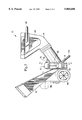
- FIG. 4 is a side sectional view taken along line 4--4 of FIG. 3;
- FIG. 5 is an exploded perspective view of the feed chute mounting and rotating assembly of this invention.
- the chipper/shredder of this invention is identified generally as apparatus 10, comprising a housing 12 having a feed chute 14 rotatably secured to the front side 16, and a chipper chute 18 fixedly secured to the rear side 20.
- Housing 12 is bounded by a peripheral outer wall 22, and includes an outlet 24 through which comminuted debris is discharged, preferably into a suitable container.
- the primary novelty of this invention is found in the rotating ability of feed chute 14, described more fully below.
- Feed chute 14 is uniquely rotatable between an upright position, as shown in FIG. 1, and a lowered position as shown in FIG. 2.
- the edge portion 26 of hopper 28 is substantially level with the ground, so that the user of apparatus 10 can easily rake or sweep leaves or other debris to be comminuted directly into hopper 28.
- Such debris is then introduced into interior 30 of housing 12 through cylindrical section 32 which communicates with interior 30 through in an inlet opening formed in front side 16.
- hopper 28 is positioned to receive debris vertically from above, with cylindrical section 32 extending angularly upwardly from side 16. It is seen that the angle of entry of cylindrical section 32 relative to front side 16 remains unchanged regardless of whether chute 14 is in its upright or lowered position.
- apparatus 10 includes a variety of cutting means disposed within housing 12 for adequately comminuting debris.
- blade 34 contacts debris introduced through chute 14, thereby reducing the debris to an acceptable size for further comminuting by flails 36 hingedly secured to rotating structure 38.
- flails 36 are disposed in groups of three, adapted to fit between stationary blades 40 projecting inwardly from outer wall 22.
- flywheel 42 includes chipper blade 44 which serves to reduce limbs and branches to smaller particles suitable for comminuting by flails 36 and stationary blades 40.
- the cutting means defined by blade 34, rotating structure 38, and flywheel 42 are rotatably driven at a relatively high speed by internal combustion engine 46, which is operatively coupled to such cutting means by drive shaft 47 extending from engine 46 through rear side 20 of housing 12. It is expected that those skilled in the art will readily understand the operation of the cutting means and engine 46 disclosed herein, and that any suitable cutting means and driving means operatively coupled thereto may be incorporated on apparatus 10 without departing from the principles of the present invention.
- Cylindrical section 32 of chute 14 is shown having annular plate 48 secured to or integrally formed with the proximate end thereof.
- Plate 48 has a plurality of arcuate slots 50 formed therein through which studs 52 are inserted for securing plate 50 to front side 16 of housing 12.
- Disposed between plate 48 and front side 16 are seals 54 and restricting plate 56, with plate 56 having an opening 58 formed therein for allowing the introduction of debris through the passageway defined by cylindrical section 32 and the inlet in front side 16 into interior 30 of housing 12. Opening 58 has offset 60 associated therewith for cooperating with blade 34 to initially reduce the debris to smaller particles.
- outer stationary ring 62 is secured onto studs 52 by means of nuts 64, thereby retaining plate 48, plate 56, and seals 54 against side 16 of housing 12.
- chute 14 The unique rotating ability of chute 14 is provided by the structure best illustrated in FIG. 5.
- plate 56 and ring 62 are fixedly secured to the front side 16 of housing 12, with plate 48 being disposed therebetween. Studs 52 (only one of which is shown) are alignable with suitable mounting holes formed in plate 56 and ring 62, and with slots 50 in plate 48.
- plate 56 and ring 62 each include three such mounting holes formed therein for aligning with three studs 52.
- Ring 62 preferably includes an annular lip 66 which fits over the outer perimeter of plates 48 and 56 and seals 54, and abuts side 16 annularly adjacent the circular inlet opening formed therein.
- Annular lip 66 thereby prevents the compressive load caused upon tightening nuts 64 from prohibiting rotational movement of plate 48 and cylindrical section 32 secured thereto.
- At least one grease fitting 68 is provided in stationary ring 62 so that the rotational assembly may be lubricated.
- three such grease fittings 68 are provided.
- Each stud 52 preferably includes a bushing 70 disposed thereon, with bushings 70 being disposed within slots 50 to facilitate the sliding movement of studs 52 within slots 50.
- Chute 14 is secured in its upright position by a locking mechanism comprising plunger 72, spring 74, retainer 76, and knob 78.
- Distal end 80 of plunger 72 fits within recess 82 formed in plate 48 adjacent slot 50, while proximate end 84 has external threads formed thereon for mating with internal threads formed within knob 78.
- Retainer 76 is secured to stationary ring 62 by a pair of rivets 86 (only one of which is shown). With chute 14 in its upright position, plate 48 is oriented such that compression spring 74 extends plunger 72 so that distal end 80 fits within recess 82 and into hole 83 in plate 56, and thereby preventing rotational movement of plate 48.
- chute 14 When it is desired to move chute 14 to its lowered position, the user simply pulls outwardly on knob 78, thereby retracting distal end 80 of plunger 72 from hole 83 in plate 56 and recess 82, and allowing free rotational movement of plate 48. Upon returning chute 14 to its upright position, spring 74 causes plunger 72 to automatically extend to its locked position operatively engaging recess 82 and hole 83.
- cylindrical section 32 provides an extremely efficient structure for introducing debris into the comminuting chamber of housing 12, particularly when angularly oriented as shown herein.
- Apparatus 10 has been found highly effective in drawing debris into housing 12 for comminuting, and it is believe that the size and shape of cylindrical section 32 contribute to the superior performance achieved with apparatus 10. Therefore, it is highly desirable to maintain the orientation of cylindrical section 32 relative to housing 12 when chute 14 is in either the upright or lowered position.
- apparatus 10 is fully portable.
- Housing 12 and engine 46 are mounted to a frame 86, which includes a pair of wheels 88 and support brace 90 operatively secured thereto.
- Hopper 28 includes a handle 92 affixed thereto which may be grasped by the user and, upon tilting apparatus 10 rearwardly so that support brace 90 is elevated slightly, pushed or pulled to move apparatus 10 as desired.
Abstract
Description
Claims (11)
Priority Applications (1)
| Application Number | Priority Date | Filing Date | Title |
|---|---|---|---|
| US08/071,570 US5860606A (en) | 1993-06-03 | 1993-06-03 | Chipper/shredder having rotatable feed chute |
Applications Claiming Priority (1)
| Application Number | Priority Date | Filing Date | Title |
|---|---|---|---|
| US08/071,570 US5860606A (en) | 1993-06-03 | 1993-06-03 | Chipper/shredder having rotatable feed chute |
Publications (1)
| Publication Number | Publication Date |
|---|---|
| US5860606A true US5860606A (en) | 1999-01-19 |
Family
ID=22102177
Family Applications (1)
| Application Number | Title | Priority Date | Filing Date |
|---|---|---|---|
| US08/071,570 Expired - Fee Related US5860606A (en) | 1993-06-03 | 1993-06-03 | Chipper/shredder having rotatable feed chute |
Country Status (1)
| Country | Link |
|---|---|
| US (1) | US5860606A (en) |
Cited By (31)
| Publication number | Priority date | Publication date | Assignee | Title |
|---|---|---|---|---|
| US6237864B1 (en) * | 1999-08-09 | 2001-05-29 | Mtd Products Inc | Chipper shredder chute |
| US6343754B1 (en) | 1999-12-21 | 2002-02-05 | Earl Ray Snow | Chipper-shredder discharge capture system |
| US6701698B1 (en) | 2003-01-10 | 2004-03-09 | Michael U. Nwosu | Apparatus for fine pulverization of dry leaves and garden debris |
| US20040168423A1 (en) * | 2003-01-10 | 2004-09-02 | Nwosu Michael U. | Apparatus for fine pulverization of dry leaves and garden debris |
| US20040216435A1 (en) * | 2003-01-10 | 2004-11-04 | Nwosu Michael U. | Apparatus for fine pulverization of dry leaves and garden debris |
| US20050193701A1 (en) * | 2004-02-18 | 2005-09-08 | Schiller-Pfeiffer, Inc. | Apparatus for processing of organic material |
| US20060024456A1 (en) * | 2004-07-27 | 2006-02-02 | O'leary Robert J | Machine for opening packages of loosefill insulation material |
| US20060024458A1 (en) * | 2004-07-27 | 2006-02-02 | O'leary Robert J | Blowing machine for loosefil insulation material |
| US20060231651A1 (en) * | 2004-07-27 | 2006-10-19 | Evans Michael E | Loosefill blowing machine with a chute |
| US20070080250A1 (en) * | 2003-02-07 | 2007-04-12 | King Machine And Tool Co. | Disc mill assembly for pulverizing system |
| US20080087751A1 (en) * | 2006-10-16 | 2008-04-17 | Johnson Michael W | Exit valve for blowing insulation machine |
| US20080089748A1 (en) * | 2006-10-16 | 2008-04-17 | Johnson Michael W | Entrance chute for blowing insulation machine |
| US20080087557A1 (en) * | 2006-10-16 | 2008-04-17 | Evans Michael E | Partially cut loosefill package |
| US20080173737A1 (en) * | 2006-10-16 | 2008-07-24 | Evans Michael E | Blowing wool machine outlet plate assembly |
| US7431231B1 (en) * | 2006-12-06 | 2008-10-07 | Tong Myong Saiki | Portable shredding device |
| US20080251155A1 (en) * | 2007-04-11 | 2008-10-16 | Todd Alan Mason | Tree and stump trimming and removal system |
| US20090083933A1 (en) * | 2007-09-27 | 2009-04-02 | Masaki Takeda | Suction device for powered apparatus |
| US20090257833A1 (en) * | 2008-04-14 | 2009-10-15 | Johnson Michael W | Blowing wool machine flow control |
| US20090314672A1 (en) * | 2006-10-16 | 2009-12-24 | Evans Michael E | Loosefill Package For Blowing Wool Machine |
| ITPD20080206A1 (en) * | 2008-07-10 | 2010-01-11 | Zanon S R L | MILL FRANGITUTTO, PARTICULARLY FOR VEGETABLE AND SIMILAR RESIDUES |
| US7731115B2 (en) | 2006-10-16 | 2010-06-08 | Owens Corning Intellectual Capital, Llc | Agitation system for blowing insulation machine |
| US20100147983A1 (en) * | 2008-12-17 | 2010-06-17 | Evans Michael E | Non-Symmetrical Airlock For Blowing Wool Machine |
| US20110024317A1 (en) * | 2009-07-30 | 2011-02-03 | Evans Michael E | Loosefill package for blowing wool machine |
| CN102500456A (en) * | 2011-01-12 | 2012-06-20 | 浙江亚特电器有限公司 | Wood chipper |
| US20130175376A1 (en) * | 2011-12-14 | 2013-07-11 | Anthony Freakes | Mulching apparatus |
| US9457355B2 (en) | 2011-09-16 | 2016-10-04 | Omachron Intellectual Property Inc. | Apparatus for converting bales of insulation to loose fill |
| US10604947B2 (en) | 2015-09-16 | 2020-03-31 | Owens Corning Intellectual Capital, Llc | Loosefill insulation blowing machine |
| US10645885B2 (en) | 2017-08-17 | 2020-05-12 | Harper Industries, Inc. | Conical inlet for debris loader |
| US10974254B1 (en) * | 2018-04-04 | 2021-04-13 | David Gerald Farrington | Hopper for shredding fibrous material |
| US20210195832A1 (en) * | 2019-12-27 | 2021-07-01 | Ash GILPIN | Leaf mulcher |
| US20220088610A1 (en) * | 2017-01-23 | 2022-03-24 | Russell Elbridge Holcomb | Foliage shredder |
Citations (24)
| Publication number | Priority date | Publication date | Assignee | Title |
|---|---|---|---|---|
| US385990A (en) * | 1888-07-10 | Fertilizer-distributer | ||
| US2658318A (en) * | 1951-10-30 | 1953-11-10 | Oliver C Miller | Suction leaf pickup and pulverizing device |
| US3338037A (en) * | 1964-10-14 | 1967-08-29 | Bauer Felix | Universal vegetal grinder and harvester |
| US3618157A (en) * | 1969-12-08 | 1971-11-09 | Charles S Bassin | Yard cleaning machine |
| US3688479A (en) * | 1971-07-15 | 1972-09-05 | Milton B Martinson | Leaf comminuting apparatus |
| US3813725A (en) * | 1972-08-17 | 1974-06-04 | Atwater Strong Co Inc | Vacuum cleaner construction |
| US3817462A (en) * | 1972-07-17 | 1974-06-18 | Mtd Prod Inc | Shredder |
| US3841571A (en) * | 1973-05-07 | 1974-10-15 | Roper Corp | Safety guard arrangement for shredder-bagger |
| US3860181A (en) * | 1973-08-08 | 1975-01-14 | Gilson Brothers Co | Shredding machine |
| US3907216A (en) * | 1973-03-26 | 1975-09-23 | Amerind Mackissic Inc | Disintegration apparatus |
| US3929236A (en) * | 1973-08-08 | 1975-12-30 | Gilson Brothers Co | Shredding machine |
| US3968938A (en) * | 1974-09-10 | 1976-07-13 | Lambert Corporation | System for handling debris |
| US4117983A (en) * | 1977-10-27 | 1978-10-03 | Browning Paul E | Leaf collector and comminutor |
| US4824034A (en) * | 1987-11-23 | 1989-04-25 | Baker Herbert R | Apparatus and method for chipping and/or shredding branches and the like |
| US4826331A (en) * | 1988-03-16 | 1989-05-02 | Baker Herbert R | Protective bearings guard |
| US4834302A (en) * | 1987-11-23 | 1989-05-30 | Baker Herbert R | Apparatus for chipping and/or shredding branches and the like |
| US4911564A (en) * | 1988-03-16 | 1990-03-27 | Baker Herbert R | Protective bearing guard |
| US4951882A (en) * | 1989-03-21 | 1990-08-28 | Ober Howard R | Combination leaf and lawn debris comminuting vacuum and wood chipper |
| US5018672A (en) * | 1989-11-27 | 1991-05-28 | Kathcon, Inc. | Organic material reduction apparatus |
| US5062329A (en) * | 1990-07-17 | 1991-11-05 | Garden Way Incorporated | Leaf tamper for chipper/shredder |
| US5085376A (en) * | 1991-05-06 | 1992-02-04 | Tolle Mfg. Co., Inc. | Commercial-grade grinding and mulching machine |
| US5156345A (en) * | 1991-07-26 | 1992-10-20 | Tornado Products, Inc. | Fan-type yard waste processing apparatus |
| US5240189A (en) * | 1991-10-25 | 1993-08-31 | Crary Company | Debris shredder and rotor |
| US5340035A (en) * | 1992-04-13 | 1994-08-23 | Ford Stuart N | Combination chipper and shredder apparatus and lawn vacuum machine |
-
1993
- 1993-06-03 US US08/071,570 patent/US5860606A/en not_active Expired - Fee Related
Patent Citations (25)
| Publication number | Priority date | Publication date | Assignee | Title |
|---|---|---|---|---|
| US385990A (en) * | 1888-07-10 | Fertilizer-distributer | ||
| US2658318A (en) * | 1951-10-30 | 1953-11-10 | Oliver C Miller | Suction leaf pickup and pulverizing device |
| US3338037A (en) * | 1964-10-14 | 1967-08-29 | Bauer Felix | Universal vegetal grinder and harvester |
| US3618157A (en) * | 1969-12-08 | 1971-11-09 | Charles S Bassin | Yard cleaning machine |
| US3688479A (en) * | 1971-07-15 | 1972-09-05 | Milton B Martinson | Leaf comminuting apparatus |
| US3817462A (en) * | 1972-07-17 | 1974-06-18 | Mtd Prod Inc | Shredder |
| US3813725A (en) * | 1972-08-17 | 1974-06-04 | Atwater Strong Co Inc | Vacuum cleaner construction |
| US3907216A (en) * | 1973-03-26 | 1975-09-23 | Amerind Mackissic Inc | Disintegration apparatus |
| US3841571A (en) * | 1973-05-07 | 1974-10-15 | Roper Corp | Safety guard arrangement for shredder-bagger |
| US3860181A (en) * | 1973-08-08 | 1975-01-14 | Gilson Brothers Co | Shredding machine |
| US3929236A (en) * | 1973-08-08 | 1975-12-30 | Gilson Brothers Co | Shredding machine |
| US3968938A (en) * | 1974-09-10 | 1976-07-13 | Lambert Corporation | System for handling debris |
| US4117983A (en) * | 1977-10-27 | 1978-10-03 | Browning Paul E | Leaf collector and comminutor |
| US4824034A (en) * | 1987-11-23 | 1989-04-25 | Baker Herbert R | Apparatus and method for chipping and/or shredding branches and the like |
| US4834302A (en) * | 1987-11-23 | 1989-05-30 | Baker Herbert R | Apparatus for chipping and/or shredding branches and the like |
| US4826331A (en) * | 1988-03-16 | 1989-05-02 | Baker Herbert R | Protective bearings guard |
| US4911564A (en) * | 1988-03-16 | 1990-03-27 | Baker Herbert R | Protective bearing guard |
| US4951882A (en) * | 1989-03-21 | 1990-08-28 | Ober Howard R | Combination leaf and lawn debris comminuting vacuum and wood chipper |
| US5018672A (en) * | 1989-11-27 | 1991-05-28 | Kathcon, Inc. | Organic material reduction apparatus |
| US5062329A (en) * | 1990-07-17 | 1991-11-05 | Garden Way Incorporated | Leaf tamper for chipper/shredder |
| US5085376A (en) * | 1991-05-06 | 1992-02-04 | Tolle Mfg. Co., Inc. | Commercial-grade grinding and mulching machine |
| US5156345A (en) * | 1991-07-26 | 1992-10-20 | Tornado Products, Inc. | Fan-type yard waste processing apparatus |
| US5240189A (en) * | 1991-10-25 | 1993-08-31 | Crary Company | Debris shredder and rotor |
| US5340035A (en) * | 1992-04-13 | 1994-08-23 | Ford Stuart N | Combination chipper and shredder apparatus and lawn vacuum machine |
| US5340035B1 (en) * | 1992-04-13 | 1997-05-06 | Studley Products Corp | Combination chipper and shredder apparatus and lawn vacuum machine |
Cited By (62)
| Publication number | Priority date | Publication date | Assignee | Title |
|---|---|---|---|---|
| US6237864B1 (en) * | 1999-08-09 | 2001-05-29 | Mtd Products Inc | Chipper shredder chute |
| US6343754B1 (en) | 1999-12-21 | 2002-02-05 | Earl Ray Snow | Chipper-shredder discharge capture system |
| US6701698B1 (en) | 2003-01-10 | 2004-03-09 | Michael U. Nwosu | Apparatus for fine pulverization of dry leaves and garden debris |
| US20040168423A1 (en) * | 2003-01-10 | 2004-09-02 | Nwosu Michael U. | Apparatus for fine pulverization of dry leaves and garden debris |
| US20040216435A1 (en) * | 2003-01-10 | 2004-11-04 | Nwosu Michael U. | Apparatus for fine pulverization of dry leaves and garden debris |
| US6877301B2 (en) | 2003-01-10 | 2005-04-12 | Michael U. Nwosu | Apparatus for fine pulverization of dry leaves and garden debris |
| US6928799B2 (en) | 2003-01-10 | 2005-08-16 | Michael U. Nwosu | Apparatus for fine pulverization of dry leaves and garden debris |
| US20070080250A1 (en) * | 2003-02-07 | 2007-04-12 | King Machine And Tool Co. | Disc mill assembly for pulverizing system |
| US7699255B2 (en) * | 2003-02-07 | 2010-04-20 | King Machine And Tool Co. | Disc mill assembly for pulverizing system |
| US20050193701A1 (en) * | 2004-02-18 | 2005-09-08 | Schiller-Pfeiffer, Inc. | Apparatus for processing of organic material |
| US20060024456A1 (en) * | 2004-07-27 | 2006-02-02 | O'leary Robert J | Machine for opening packages of loosefill insulation material |
| US20060231651A1 (en) * | 2004-07-27 | 2006-10-19 | Evans Michael E | Loosefill blowing machine with a chute |
| US9272287B2 (en) | 2004-07-27 | 2016-03-01 | Owens Corning Intellectual Capital Llc | Blowing wool bag and method of using the bag |
| US7971813B2 (en) | 2004-07-27 | 2011-07-05 | Owens Corning Intellectual Capital, Llc | Blowing machine for loosefill insulation material |
| US7938348B2 (en) | 2004-07-27 | 2011-05-10 | Owens Corning Intellectual Capital, Llc | Loosefill blowing machine with a chute |
| US20060024458A1 (en) * | 2004-07-27 | 2006-02-02 | O'leary Robert J | Blowing machine for loosefil insulation material |
| US20090206105A1 (en) * | 2004-07-27 | 2009-08-20 | O'leary Robert J | Blowing Wool Bag And Method Of Using The Bag |
| US20100031602A1 (en) * | 2004-07-27 | 2010-02-11 | O'leary Robert J | Blowing Machine For Loosefil Insulation Material |
| US7819349B2 (en) * | 2006-10-16 | 2010-10-26 | Owens Corning Intellectual Capital, Llc | Entrance chute for blowing insulation machine |
| US20080087557A1 (en) * | 2006-10-16 | 2008-04-17 | Evans Michael E | Partially cut loosefill package |
| US8087601B2 (en) | 2006-10-16 | 2012-01-03 | Owens Corning Intellectual Capital, Llc | Agitation system for blowing wool machine |
| US20110226881A1 (en) * | 2006-10-16 | 2011-09-22 | Johnson Michael W | Agitation system for blowing wool machine |
| US20090314672A1 (en) * | 2006-10-16 | 2009-12-24 | Evans Michael E | Loosefill Package For Blowing Wool Machine |
| US7980498B2 (en) | 2006-10-16 | 2011-07-19 | Owens-Corning Fiberglas Technology, Inc. | Entrance chute for blowing wool machine |
| US20090173645A2 (en) * | 2006-10-16 | 2009-07-09 | Michael Evans | Partially Cut Loosefill Package |
| US20080089748A1 (en) * | 2006-10-16 | 2008-04-17 | Johnson Michael W | Entrance chute for blowing insulation machine |
| US7712690B2 (en) | 2006-10-16 | 2010-05-11 | Owens Corning Intellectual Capital, Llc | Exit valve for blowing insulation machine |
| US7731115B2 (en) | 2006-10-16 | 2010-06-08 | Owens Corning Intellectual Capital, Llc | Agitation system for blowing insulation machine |
| US20080087751A1 (en) * | 2006-10-16 | 2008-04-17 | Johnson Michael W | Exit valve for blowing insulation machine |
| US8245960B2 (en) | 2006-10-16 | 2012-08-21 | Owens Corning Intellectual Capital, Llc | Agitation system for blowing wool machine |
| US20100219274A1 (en) * | 2006-10-16 | 2010-09-02 | Johnson Michael W | Agitation system for blowing wool machine |
| US20080173737A1 (en) * | 2006-10-16 | 2008-07-24 | Evans Michael E | Blowing wool machine outlet plate assembly |
| US7845585B2 (en) | 2006-10-16 | 2010-12-07 | Owens Corning Intellectual Capital, Llc | Blowing wool machine outlet plate assembly |
| US9004382B2 (en) | 2006-10-16 | 2015-04-14 | Owens Corning Intellectual Capital, Llc | Agitation system for blowing wool machine |
| US7882947B2 (en) | 2006-10-16 | 2011-02-08 | Owens Corning Intellectual Capital, Llc | Partially cut loosefill package |
| US7913842B2 (en) | 2006-10-16 | 2011-03-29 | Owens Corning Intellectual Capital, Llc | Loosefill package for blowing wool machine |
| US7431231B1 (en) * | 2006-12-06 | 2008-10-07 | Tong Myong Saiki | Portable shredding device |
| US20080251155A1 (en) * | 2007-04-11 | 2008-10-16 | Todd Alan Mason | Tree and stump trimming and removal system |
| US8365349B2 (en) * | 2007-09-27 | 2013-02-05 | Yamabiko Corp. | Suction device for powered apparatus |
| US20090083933A1 (en) * | 2007-09-27 | 2009-04-02 | Masaki Takeda | Suction device for powered apparatus |
| US7762484B2 (en) | 2008-04-14 | 2010-07-27 | Owens Corning Intellectual Capital, Llc | Blowing wool machine flow control |
| US20090257833A1 (en) * | 2008-04-14 | 2009-10-15 | Johnson Michael W | Blowing wool machine flow control |
| ITPD20080206A1 (en) * | 2008-07-10 | 2010-01-11 | Zanon S R L | MILL FRANGITUTTO, PARTICULARLY FOR VEGETABLE AND SIMILAR RESIDUES |
| US7971814B2 (en) | 2008-12-17 | 2011-07-05 | Owens Corning Intellectual Capital, Llc | Non-symmetrical airlock for blowing wool machine |
| US20100147983A1 (en) * | 2008-12-17 | 2010-06-17 | Evans Michael E | Non-Symmetrical Airlock For Blowing Wool Machine |
| US7886904B1 (en) | 2009-07-30 | 2011-02-15 | Owens Corning Intellectual Capital, Llc | Loosefill package for blowing wool machine |
| US20110024317A1 (en) * | 2009-07-30 | 2011-02-03 | Evans Michael E | Loosefill package for blowing wool machine |
| CN102500456A (en) * | 2011-01-12 | 2012-06-20 | 浙江亚特电器有限公司 | Wood chipper |
| CN102500456B (en) * | 2011-01-12 | 2013-10-09 | 浙江亚特电器有限公司 | Wood chipper |
| US9457355B2 (en) | 2011-09-16 | 2016-10-04 | Omachron Intellectual Property Inc. | Apparatus for converting bales of insulation to loose fill |
| US9186682B2 (en) * | 2011-12-14 | 2015-11-17 | Anthony Freakes | Mulching apparatus |
| US20160081278A1 (en) * | 2011-12-14 | 2016-03-24 | Anthony Freakes | Mulching apparatus |
| US20130175376A1 (en) * | 2011-12-14 | 2013-07-11 | Anthony Freakes | Mulching apparatus |
| US10604947B2 (en) | 2015-09-16 | 2020-03-31 | Owens Corning Intellectual Capital, Llc | Loosefill insulation blowing machine |
| US10669727B2 (en) | 2015-09-16 | 2020-06-02 | Owens Corning Intellectual Capital, Llc | Loosefill insulation blowing machine |
| US11492812B2 (en) | 2015-09-16 | 2022-11-08 | Owens Corning Intellectual Capital, Llc | Loosefill insulation blowing machine |
| US11634915B2 (en) | 2015-09-16 | 2023-04-25 | Owens Corning Intellectual Capital, Llc | Loosefill insulation blowing machine |
| US20220088610A1 (en) * | 2017-01-23 | 2022-03-24 | Russell Elbridge Holcomb | Foliage shredder |
| US10645885B2 (en) | 2017-08-17 | 2020-05-12 | Harper Industries, Inc. | Conical inlet for debris loader |
| US10974254B1 (en) * | 2018-04-04 | 2021-04-13 | David Gerald Farrington | Hopper for shredding fibrous material |
| US20210195832A1 (en) * | 2019-12-27 | 2021-07-01 | Ash GILPIN | Leaf mulcher |
| US11812687B2 (en) * | 2019-12-27 | 2023-11-14 | Ash GILPIN | Leaf mulcher |
Similar Documents
| Publication | Publication Date | Title |
|---|---|---|
| US5860606A (en) | Chipper/shredder having rotatable feed chute | |
| US5231827A (en) | Lawn and garden chipper shredder vacuum apparatus | |
| US4226074A (en) | Lawnmower deck | |
| US5018672A (en) | Organic material reduction apparatus | |
| US5381970A (en) | Combination chipper/shredder and vacuum apparatus for lawns and gardens | |
| US4951882A (en) | Combination leaf and lawn debris comminuting vacuum and wood chipper | |
| US3817462A (en) | Shredder | |
| US5669563A (en) | Chipper shredder with use-enhancing features | |
| US5638668A (en) | Lawn mower having nested deck and liner | |
| US5102056A (en) | Combination leaf and lawn debris comminuting vacuum and wood chipper | |
| US4057952A (en) | Rotary mower and shredder device | |
| US4477029A (en) | Shredding machine | |
| US4258539A (en) | Grass discharge chute deflector for rotary lawn mower | |
| US3790094A (en) | Mobile leaf pulverizer | |
| US6862871B2 (en) | Hybrid mower, edger, trimmer, blower | |
| US5156345A (en) | Fan-type yard waste processing apparatus | |
| US3884020A (en) | Leaf shredding means for rotary mowers | |
| US6062013A (en) | Mulching mower with uniform cut and particulate distribution | |
| US3850364A (en) | Portable compost grinding apparatus | |
| US5385308A (en) | Chipper-shredder | |
| US3808782A (en) | Shredder adaptor | |
| US3974629A (en) | Lawn mower with improved mulching attachment | |
| US5340035A (en) | Combination chipper and shredder apparatus and lawn vacuum machine | |
| EP0616760A1 (en) | Apparatus for the treatment of lawns | |
| US3716090A (en) | Garden shredder with variable position loading chute |
Legal Events
| Date | Code | Title | Description |
|---|---|---|---|
| AS | Assignment |
Owner name: NOMA OUTDOOR PRODUCTS, INC. A TENNESSEE CORPORAT Free format text: ASSIGNMENT OF ASSIGNORS INTEREST;ASSIGNORS:TIEDEMAN, DAVID A.;HENNINGER, CHARLES S.;REEL/FRAME:006616/0781 Effective date: 19930521 |
|
| AS | Assignment |
Owner name: MURRAY OUTDOOR PRODUCTS, INC. Free format text: ASSIGNMENT OF ASSIGNORS INTEREST;ASSIGNOR:NOMA OUTDOOR PRODUCTS, INC.;REEL/FRAME:007418/0107 Effective date: 19950321 |
|
| AS | Assignment |
Owner name: MURRAY, INC., TENNESSEE Free format text: MERGER AND CHANGE OF NAME;ASSIGNORS:NOMA INDUSTRIES;NOMA OUTDOOR PRODUCTS, INC.;WESTERN INTERNATIONAL INCORPORATED;AND OTHERS;REEL/FRAME:007666/0694 Effective date: 19870908 |
|
| AS | Assignment |
Owner name: GENERAL ELECTRIC CAPITAL CORPORATION, AS AGENT, IL Free format text: SECURITY AGREEMENT;ASSIGNOR:MURRAY, INC.;REEL/FRAME:011333/0036 Effective date: 20001005 |
|
| FPAY | Fee payment |
Year of fee payment: 4 |
|
| AS | Assignment |
Owner name: BRIGGS & STRATTON POWER PRODUCTS GROUP, LLC, WISCO Free format text: ASSIGNMENT OF ASSIGNORS INTEREST;ASSIGNOR:MURRAY, INC.;REEL/FRAME:016016/0600 Effective date: 20050211 |
|
| REMI | Maintenance fee reminder mailed | ||
| LAPS | Lapse for failure to pay maintenance fees | ||
| STCH | Information on status: patent discontinuation |
Free format text: PATENT EXPIRED DUE TO NONPAYMENT OF MAINTENANCE FEES UNDER 37 CFR 1.362 |
|
| FP | Lapsed due to failure to pay maintenance fee |
Effective date: 20070119 |