US5889341A - Multi-functional apparatus employing a linear wiper - Google Patents
Multi-functional apparatus employing a linear wiper Download PDFInfo
- Publication number
- US5889341A US5889341A US08/947,916 US94791697A US5889341A US 5889341 A US5889341 A US 5889341A US 94791697 A US94791697 A US 94791697A US 5889341 A US5889341 A US 5889341A
- Authority
- US
- United States
- Prior art keywords
- stator
- linear motor
- motion mechanism
- intermittent motion
- armature
- Prior art date
- Legal status (The legal status is an assumption and is not a legal conclusion. Google has not performed a legal analysis and makes no representation as to the accuracy of the status listed.)
- Expired - Fee Related
Links
Images


Classifications
-
- E—FIXED CONSTRUCTIONS
- E05—LOCKS; KEYS; WINDOW OR DOOR FITTINGS; SAFES
- E05B—LOCKS; ACCESSORIES THEREFOR; HANDCUFFS
- E05B83/00—Vehicle locks specially adapted for particular types of wing or vehicle
- E05B83/16—Locks for luggage compartments, car boot lids or car bonnets
-
- B—PERFORMING OPERATIONS; TRANSPORTING
- B60—VEHICLES IN GENERAL
- B60S—SERVICING, CLEANING, REPAIRING, SUPPORTING, LIFTING, OR MANOEUVRING OF VEHICLES, NOT OTHERWISE PROVIDED FOR
- B60S1/00—Cleaning of vehicles
- B60S1/02—Cleaning windscreens, windows or optical devices
- B60S1/04—Wipers or the like, e.g. scrapers
- B60S1/06—Wipers or the like, e.g. scrapers characterised by the drive
- B60S1/08—Wipers or the like, e.g. scrapers characterised by the drive electrically driven
-
- B—PERFORMING OPERATIONS; TRANSPORTING
- B60—VEHICLES IN GENERAL
- B60S—SERVICING, CLEANING, REPAIRING, SUPPORTING, LIFTING, OR MANOEUVRING OF VEHICLES, NOT OTHERWISE PROVIDED FOR
- B60S1/00—Cleaning of vehicles
- B60S1/02—Cleaning windscreens, windows or optical devices
- B60S1/04—Wipers or the like, e.g. scrapers
- B60S1/32—Wipers or the like, e.g. scrapers characterised by constructional features of wiper blade arms or blades
- B60S1/34—Wiper arms; Mountings therefor
- B60S1/3402—Wiper arms; Mountings therefor with means for obtaining particular wiping patterns
- B60S1/3404—Wiper arms; Mountings therefor with means for obtaining particular wiping patterns the wiper blades being moved substantially parallel with themselves
-
- B—PERFORMING OPERATIONS; TRANSPORTING
- B60—VEHICLES IN GENERAL
- B60S—SERVICING, CLEANING, REPAIRING, SUPPORTING, LIFTING, OR MANOEUVRING OF VEHICLES, NOT OTHERWISE PROVIDED FOR
- B60S1/00—Cleaning of vehicles
- B60S1/02—Cleaning windscreens, windows or optical devices
- B60S1/56—Cleaning windscreens, windows or optical devices specially adapted for cleaning other parts or devices than front windows or windscreens
- B60S1/58—Cleaning windscreens, windows or optical devices specially adapted for cleaning other parts or devices than front windows or windscreens for rear windows
- B60S1/583—Cleaning windscreens, windows or optical devices specially adapted for cleaning other parts or devices than front windows or windscreens for rear windows including wiping devices
-
- H—ELECTRICITY
- H02—GENERATION; CONVERSION OR DISTRIBUTION OF ELECTRIC POWER
- H02K—DYNAMO-ELECTRIC MACHINES
- H02K41/00—Propulsion systems in which a rigid body is moved along a path due to dynamo-electric interaction between the body and a magnetic field travelling along the path
- H02K41/02—Linear motors; Sectional motors
- H02K41/03—Synchronous motors; Motors moving step by step; Reluctance motors
-
- B—PERFORMING OPERATIONS; TRANSPORTING
- B60—VEHICLES IN GENERAL
- B60S—SERVICING, CLEANING, REPAIRING, SUPPORTING, LIFTING, OR MANOEUVRING OF VEHICLES, NOT OTHERWISE PROVIDED FOR
- B60S1/00—Cleaning of vehicles
- B60S1/02—Cleaning windscreens, windows or optical devices
- B60S1/04—Wipers or the like, e.g. scrapers
- B60S1/0491—Additional elements being fixed on wipers or parts of wipers not otherwise provided for, e.g. covers, antennae or lights
-
- Y—GENERAL TAGGING OF NEW TECHNOLOGICAL DEVELOPMENTS; GENERAL TAGGING OF CROSS-SECTIONAL TECHNOLOGIES SPANNING OVER SEVERAL SECTIONS OF THE IPC; TECHNICAL SUBJECTS COVERED BY FORMER USPC CROSS-REFERENCE ART COLLECTIONS [XRACs] AND DIGESTS
- Y10—TECHNICAL SUBJECTS COVERED BY FORMER USPC
- Y10T—TECHNICAL SUBJECTS COVERED BY FORMER US CLASSIFICATION
- Y10T74/00—Machine element or mechanism
- Y10T74/20—Control lever and linkage systems
- Y10T74/20012—Multiple controlled elements
Definitions
- This invention relates generally to multi-functional apparatuses and specifically to a multi-functional apparatus employing a linear motor for use in an automotive vehicle.
- a window wiper assembly for cleaning rear windows of automotive vehicles.
- these types of rear window wiper assemblies include a wiper blade mounted upon a bracket which is coupled to a wiper arm.
- the wiper arm is attached to a wiper shaft rotatably driven in a cyclical oscillating manner by a helical gear.
- a reversible, fractional horsepower, dc electric motor serves to actuate the helical gear through an armature shaft-mounted worm gear enmeshed therewith.
- This type of rear window wiper arrangement is usually mounted upon a pivoting liftgate of a minivan, station wagon, sport-utility vehicle or the like. Examples of conventional window wiper assemblies and motor mechanisms are disclosed within the following U.S. Patents: U.S.
- linear-motion wiper structures have been proposed as an alternative to conventional arcuate-motion wiper structures.
- One such structure comprises a multi-stage hydraulic cylinder arm which can be driven by a transmission mechanism having both vertical and horizontal displacement functionality whereby a blade, which is driven by the arm, can wipe on the windshield in a linear reciprocating motion so as to completely clear the drops of rain on the windshield, and this may provide a clear vision for users who drive in the rain.
- An example of this structure is disclosed in U.S. Pat. No. 4,782,548 which issued to Wong on Nov. 8, 1988, the entire disclosure of which is hereby incorporated by reference.
- This apparatus for wiping a window has a wiper, a first track substantially parallel to at least a portion of the window and a second track substantially parallel to and displaced from the first track.
- a first motorized drive wheel is provided for driving the wiper along the first track in a first direction and a second motorized drive wheel for driving the wiper along the second track in a second direction, opposite to the first direction, so as to wipe the window.
- the wiper is preferably designed to reduce drag-back of water across the window.
- curved connecting tracks connect between the ends of the first track and the second track so as to form a closed loop track.
- a single motorized drive wheel is used.
- the single motorized drive wheel may be driven by a motor rotatably associated with the wiper, or through a flexible drive cable by a remotely mounted motor.
- Other embodiments use a single substantially linear track in combination with a motor running unidirectionally.
- An example of this structure is disclosed in U.S. Pat. No. 5,564,156 which issued to Habba on Oct. 15, 1996, the entire disclosure of which is hereby incorporated by reference.
- Some conventional vehicles also provide a rear window release lock or latch, actuated by a solenoid, which can be unlocked to allow for upward pivotal movement of the rear window in relation to the otherwise stationary liftgate.
- a separate liftgate lock is often mounted upon the liftgate door for fastening the liftgate to the body to prevent inadvertent pivotal opening.
- This liftgate lock is traditionally operated by manual key or handle rotation, or through a separate electric motor or solenoid.
- a single electromagnetic device selectively causes movement of the intermittent motion mechanisms thereby moving mechanical devices coupled thereto.
- the armature shaft of an electric motor rotates a worm gear segment which then drives a helical gear mounted in a gear housing.
- this input can be made to drive selectively two or three intermittent rotary motion mechanisms according to the rotary position of the helical gear.
- Mechanical devices which are coupled to the intermittent rotary motion mechanisms e.g., a rear window wiper, a liftgate lock and a liftgate window release lock, are therefore operated according to the positional range of oscillation or movement of the helical gear.
- a multi-functional apparatus employing an electromagnetic device.
- the multi-functional apparatus employs a single electromagnetic device to selectively actuate a plurality of intermittent motion mechanisms, thereby operating mechanical devices attached thereto.
- a reversible dc electric motor selectively drives a rear window wiper via a transmission, a clutch and a driven shaft. By rotating the transmission member beyond the rotational range for operating the wiper, drive to the wiper is disengaged and a locking mechanism for the rear window or liftgate can also be actuated by the rotating transmission member.
- a single electric motor selectively actuates three intermittent motion mechanisms thereby causing three mechanical devices coupled thereto to operate (e.g., rear window and liftgate locking mechanisms and a window wiper).
- three mechanical devices coupled thereto e.g., rear window and liftgate locking mechanisms and a window wiper.
- a control system for an automotive vehicle multi-functional apparatus employs an electronic control unit operably controlling a rear window wiper assembly.
- an electronic control unit is operable as a multiplexed rear node for controlling a variety of liftgate devices and functions.
- an electronic control unit controls a single multi-functional electromagnetic device.
- the multi-functional electromagnetic device uses intermittent motion mechanisms to selectively operate differing devices driven therefrom.
- a method of operating the electronic control unit is also provided.
- the preferred embodiment of a multi-functional apparatus employs an intermittent motion mechanism.
- An electromagnetic device selectively causes movement of the intermittent motion mechanism thereby moving a mechanical device coupled thereto.
- a pair of intermittent motion mechanisms are selectively actuated by a single reversible electric motor.
- a single electric motor selectively actuates three intermittent motion mechanisms thereby causing three mechanical devices to operate.
- a linear wiper is mechanically coupled to a linear electric motor.
- the multi-functional apparatus of the present invention is advantageous over conventional systems since the present invention combines many different functions into a single apparatus.
- the multi-functional apparatus of the present invention replaces the traditional separate rear wiper motor, liftgate lock motor and rear window lock solenoid.
- the multi-functional apparatus of the present invention significantly reduces the piece cost, assembly cost, part proliferation and handling costs, wiring costs, and battery current consumption as compared to conventional constructions.
- the multi-functional apparatus of the present invention significantly reduces weight and packaging space requirements while increasing the electrical and mechanical reliability of the affected systems. Objectional motor and solenoid noises are also reduced.
- the present invention provides a linear-motion wiper structure which can provide a clear vision for the users when driving in the rain so as to increase the driving security.
- the present invention provides a linear-motion wiper structure which adapts to different windshields, and the blade of the wiper structure can wipe in a horizontal reciprocating motion on the windshield so as to provide an excellent vision for users. Furthermore, the linear-motion wiper of the present invention wipes a greater surface area of a window than an arcuate-motion wiper. Additionally, the linear-motion wiper of the present invention will wipe the entire surface of the window, as opposed to the 140 degree sweep of conventional arcuate-motion wipers. Moreover, the present invention provides a linear-motion wiper structure which can cooperate with a power supply to drive the blade of the wiper structure so as to provide a more practical application. Furthermore, the present invention provides a linear-motion wiper structure which can cooperate with the pair of intermittent motion mechanisms and devices associated therewith. Additional advantages and features of the present invention will become apparent from the following description and appended claims, taken in conjunction with the accompanying drawings.
- FIG. 1 is a front elevational view showing the preferred embodiment of a multi-functional apparatus of the present invention
- FIG. 2 is a partial fragmentary view of a portion of a multi-functional apparatus of the present invention.
- FIG. 3 is a partial sectional view of a portion of a multi-functional apparatus of the present invention.
- FIG. 4 is a front elevational view illustrating a window wiper assembly of a multi-functional apparatus of the present invention in a parked position;
- FIG. 5 is a front elevational view illustrating the window wiper assembly of a multi-functional apparatus of the present invention in a midway position on the window;
- FIG. 6 is a front elevational view illustrating the window wiper assembly of a multi-functional apparatus of the present invention in a terminal position on the window;
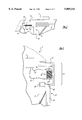
- FIG. 7 is a partial fragmentary view of the linear motor of a multi-functional apparatus of the present invention as the linear motor is about to actuate the liftgate unlock function of the liftgate unlock/lock actuator;
- FIG. 8 is a partial fragmentary view of the linear motor of a multi-functional apparatus of the present invention as the linear motor actuates the liftgate unlock function of the liftgate unlock/lock actuator;
- FIG. 9 is a partial fragmentary view of the linear motor of a multi-functional apparatus of the present invention as the linear motor actuates the window release latch actuator;
- FIG. 10 is a partial fragmentary view of the linear motor of a multi-functional apparatus of the present invention as the linear motor actuates the liftgate lock function of the liftgate unlock/lock actuator;
- FIG. 11 is a partial fragmentary view of the linear motor of a multi-functional apparatus of the present invention as the linear motor returns to a parked position.
- An automobile vehicle such as a minivan, station wagon, or sport utility vehicle or the like, has a rear liftgate door which can pivot about an upper pair of hinges coupled to the vehicle body structure.
- a cargo space is accessible from behind the vehicle.
- FIG. 1 Such a liftgate is shown in FIG. 1.
- Liftgate 1 has a rear window or backlite 2 pivotable between a closed position, substantially flush with the outer surface of liftgate 1, to an open position about upper hinges.
- a pair of pneumatic cylinders 3 and 4 act to push window 2 toward the open position when a lower portion of window 2 is released.
- the preferred embodiment of a multi-functional apparatus 5 of the present invention is mounted upon an outer surface of liftgate 1. A portion of apparatus 5 may be hidden by an exterior trim panel (not shown).
- Apparatus 5 primarily includes a linear motor 6, a controller 7, a window wiper assembly 8, a window release latch or lock actuator 9, window release latch or lock 10 mechanism, liftgate unlock/lock actuator 11, and liftgate unlock/lock mechanism 12, all of which are mounted upon liftgate 1.
- Examples of such locks are disclosed within the following U.S. patents: U.S. Pat. No. 5,222,775 entitled “Power Operated Latch Device for Automotive Back Door” which issued to Kato on Jun. 29, 1993; U.S. Pat. No. 4,422,522 entitled “Inertial Lock for Vehicle Door Latch” which issued to Slavin et al. on Dec. 27, 1983; and, U.S. Pat. No. 3,917,330 entitled “Electric Lock Release” which issued to Quantz on Nov. 4, 1975, the entire specifications of which are incorporated herein by reference.
- linear motor 6 is best illustrated in FIGS. 2-3.
- Linear motor 6 may be comprised of any number of readily commercially available linear motors, such as those available from Compumotor Corporation (Petaluma, Calif.). Although linear motor 6 is shown mounted to the upper position of tailgate 1, it could also be mounted to the lower portion of tailgate 1, or any other suitable portion of an automobile.
- linear motor 6 includes at least one stator 13 and/or 13a and an armature 14 which is disposed in housing 15.
- Armature 14 generally is oriented above stator 13, if one stator is employed. If two stators are employed, one is positioned above armature 14 and one is positioned below armature 14 so as to preferably align vertically.
- Housing 15 may ride in a groove or series of grooves 16, and thus is slidably mounted onto tailgate 1. Since armature 14 is attached to housing 15, it is important for housing 15 to be able to move freely in conjunction with the relative movements of armature 14.
- Stator 13 comprises at least one elongated structural unit of magnetically conductive material.
- this magnetically conductive material is a series of tightly wound metallic coils.
- a controller 7 is used to control the amount and duration of current flowing to each individual coil of stator 13. Controller 7 is electrically connected to stator 13 by a plurality of wires 17. Alternatively, if a second stator is employed (i.e., stator 13a), it too would be electrically connected to controller 7 in the same manner. Although only a limited number of wires 17 are shown, it should be appreciated that each individual coil has its own individual wire 17 connecting that individual coil to controller 7. Armature 14, which is generally a tightly wound series of metallic coils, and is preferably a permanent magnet, is affected by the electromagnetic field induced in stator 13. As a result, armature 14 generally moves in a direction along stator 13 in response to the current being applied by controller 7.
- Controller 7 can move armature 14 both left and right with respect to stator 13. Controller 7 can also cause armature 14 to stop moving at any point along stator 13. Controller 7 preferably uses pulse width modulation (PWM) to control the relative movements of armature 14. PWM is generally defined as using a control circuit to pulse current into coils, thereby inducing an electromagnetic field. This electromagnetic field will attract the armature. By controlling the amount of time this electromagnetic field is active and the time (width) as to when the following or adjacent coil is energized, speed and torque of a moving armature can be governed.
- PWM pulse width modulation
- Linear motor 6 is referred to as an intermittent motion mechanism due to the fact that it does not always need to be in motion, as will become apparent from the following description.
- Linear motor 6 is used, among other things, for providing locomotion for wiper assembly 8 in order to wipe window 2.
- Wiper assembly 8 is preferably mounted to housing 15 by a spring biased pivot pin 18. This allows wiper assembly 8 to pivot upwardly and outwardly when liftgate 1 is opened.
- a typical wiper assembly generally includes a wiper arm and a wiper blade, which is typically slidably mounted or received on the wiper arm.
- the wiper blade superstructure 19 is directly mounted to housing 15, thus eliminating the need for a wiper arm.
- wiper assembly 8 is shown near the left periphery of window 2. This position is designated as the parked position for reference purposes. If a person wishes to initiate a wiping operation upon window 2, an actuator (typically located on an instrument panel or other control panel) sends an electrical signal to controller 7 to apply a current to stator 13. The current applied by controller 7 may come from the automobile's main power supply or controller 7 may have its own dedicated power supply (either ac or dc current). Controller 7 then sends a current through the plurality of wires 17 to the individual coils of stator 13 which are immediately adjacent to the right side of armature 14. At that point, an electromagnetic field is induced in that particular portion of stator 13.
- an actuator typically located on an instrument panel or other control panel
- Controller 7 then sends a current through the plurality of wires 17 to the individual coils of stator 13 which are immediately adjacent to the right side of armature 14. At that point, an electromagnetic field is induced in that particular portion of stator 13.
- armature 14 In response to this electromagnetic field, armature 14 is attracted toward those coils in the direction of the arrow. As armature 14 moves, wiper assembly 8 moves a like distance. As wiper assembly 8 moves, wiper blade 19 moves a like distance. In this manner window 2 is wiped.
- wiper assembly 8 is shown at a midway point on window 2. This was accomplished by selectively and sequentially energizing the coils of stator 13 which lie to the right of armature 14, and selectively and sequentially deenergizing the coils of stator 13 which lie to the left of armature 14. This function is accomplished by controller 7.
- wiper assembly 8 is shown at a terminal position on window 2. It is referred to as a terminal position because it marks the end of the initial wipe cycle. Additionally, it is the furthest position that wiper assembly 8 can assume adjacent to the right periphery of window 2. At this point, wiper assembly 8 is ready to make the return wipe stroke back to the parked position shown in FIG. 4.
- controller 7 must selectively and sequentially energize the individual coils of stator 13 so as to cause armature 14 to move in a direction that is opposite that of the initial wipe cycle. This is accomplished by selectively reversing the polarity of the individual coils of stator 13.
- the coils immediately adjacent to the left side of armature 14 are energized so as to attract armature 14 in the direction of the arrow.
- the coils immediately adjacent to the right side of armature 14 are deenergized so as to repel armature 14 in the direction of the arrow.
- the coils are selectively and sequentially energized and deenergized until wiper assembly 8 returns to the parked position as shown in FIG. 4. At that point another wipe cycle can take place (e.g. in rainy conditions) or stator 13 can be completely deenergized (e.g. shutting the window wiper function off once the rainy conditions have subsided).
- wiper assembly 8 moves in a linearly reciprocating manner. That is, wiper assembly 8 moves back and forth in a straight line across window 2, as opposed to a conventional arcuate manner.
- the speed at which wiper assembly 8 moves across the window 2 can be controlled by controller 7.
- controller 7 For example, a rotary dial on the instrument panel or control panel would allow a person to select an infinite number of speeds at which wiper assembly 8 would function by increasing/decreasing the energization/deenergization time intervals of the individual coils of stator 13.
- Apparatus 5 is also useful for actuating several other intermittent motion mechanisms, such as liftgate unlock/lock mechanisms and window release lock or latch mechanisms.
- linear motor 6 actuates liftgate unlock/lock actuator 11 and window release latch actuator 9.
- Lifegate unlock/lock actuator 11 and window release latch actuator 9 are located in close proximity to the left periphery of stator 13.
- Liftgate unlock/lock actuator 11 and window release latch actuator 9 can be comprised of toggle switches or other suitable means for actuating such as first class levers, second class levers, or linkages.
- armature 14 of linear motor 6 will actuate liftgate unlock/lock actuator 11 and window release latch actuator 9, this can equally be accomplished by housing 15 or some other projection mounted on linear motor 6.
- liftgate unlock/lock actuator 11 and window release latch actuator 9 are actuated by having one of their respective surfaces physically urged or abutted by a surface portion of linear motor 6, preferably armature 14.
- armature 14 is removably fastened to housing 15 by means of a clip or like device.
- wiper assembly 8 and housing 15 remain in the park position, while armature 14 disengages from housing 15 and moves to the left of the left periphery of window 2 so as to be able to actuate liftgate unlock/lock actuator 11 and window release latch actuator 9.
- armature 14 would preferably need an additional support means, other than housing 15, in order to allow armature 14 to travel to the left of the left periphery of window 2.
- Liftgate unlock/lock actuator 11 and window release latch actuator 9 are either mechanically or electrically connected to liftgate unlock/lock mechanism 12 and window release latch mechanism 10, respectively. If they are electrically connected, a wire harness 20 is preferably used. If they are mechanically connected, a pulley system, a lever system, a tension wire system, a cable system, or other suitable system can be employed to effect actuation of liftgate unlock/lock mechanism 12 and window release latch mechanism 10, respectively.
- controller 7 In order to actuate liftgate unlock/lock actuator 11 and window release latch actuator 9, it is necessary to move linear motor 6 to the left of its park position as illustrated in FIG. 4. In order to accomplish this, controller 7 must selectively and sequentially apply a current to the coils of stator 13 which lie to the left of armature 14.
- FIG. 7 a current has been selectively and sequentially applied to the coils immediately adjacent to the left side of armature 14. This current has induced an electromagnetic field in that portion of stator 13, thus attracting armature 14 in the direction of the arrow.
- FIG. 7 clearly illustrates that armature 14 has moved slightly to the left toward liftgate unlock/lock actuator 11 and window release latch actuator 9, and away from window 2.
- FIG. 7 shows housing 15 and the associated wiper assembly 8 also moving to the left, it should be appreciated that it is envisioned that armature 14 may disengage from housing 15. Thus, only armature 14 would move to the left.
- FIG. 8 shows housing 15 and the associated wiper assembly 8 also moving to the left, it should be appreciated that it is envisioned that armature 14 may disengage from housing 15. Thus, only armature 14 would move to the left.
- FIG. 9 shows housing 15 and the associated wiper assembly 8 also moving to the left, it should be appreciated that it is envisioned that armature 14 may disengage from housing 15. Thus, only armature 14 would move to the left.
- FIG. 10 the polarity of the coils of stator 13 is reversed by controller 7 so as to be able to move armature 14 back to the right in the direction of the arrow. At this point a surface of armature 14 is urging up against, or abutting a surface of liftgate unlock/lock actuator 11, thus actuating the lock function of liftgate unlock/lock mechanism 12.
- FIG. 10 shows housing 15 and the associated wiper assembly 8 also moving to the right, it should be appreciated that it is envisioned that armature 14 may disengage from housing 15. Thus, only armature 14 would move to the right.
- linear motor 6 has returned to the parked position, similar to that shown in FIG. 4.
Abstract
Description
Claims (20)
Priority Applications (1)
| Application Number | Priority Date | Filing Date | Title |
|---|---|---|---|
| US08/947,916 US5889341A (en) | 1997-10-09 | 1997-10-09 | Multi-functional apparatus employing a linear wiper |
Applications Claiming Priority (1)
| Application Number | Priority Date | Filing Date | Title |
|---|---|---|---|
| US08/947,916 US5889341A (en) | 1997-10-09 | 1997-10-09 | Multi-functional apparatus employing a linear wiper |
Publications (1)
| Publication Number | Publication Date |
|---|---|
| US5889341A true US5889341A (en) | 1999-03-30 |
Family
ID=25486988
Family Applications (1)
| Application Number | Title | Priority Date | Filing Date |
|---|---|---|---|
| US08/947,916 Expired - Fee Related US5889341A (en) | 1997-10-09 | 1997-10-09 | Multi-functional apparatus employing a linear wiper |
Country Status (1)
| Country | Link |
|---|---|
| US (1) | US5889341A (en) |
Cited By (5)
| Publication number | Priority date | Publication date | Assignee | Title |
|---|---|---|---|---|
| EP1238874A1 (en) * | 2001-03-07 | 2002-09-11 | Joachim Büse | Window wiper |
| US20100007178A1 (en) * | 2006-03-28 | 2010-01-14 | Webasto Ag | System for opening/closing a roof panel and a branched driving cable to be used for the system |
| CN104038128A (en) * | 2014-05-28 | 2014-09-10 | 浙江理工大学 | NURBS (Non Uniform Rational B Spline) based linear motor thrust fluctuation control method |
| US20190061649A1 (en) * | 2017-08-24 | 2019-02-28 | John E. Hilliker | Integrated liftgate wire harness tether |
| EP3944994A1 (en) * | 2020-07-29 | 2022-02-02 | Rosemount Aerospace Inc. | Electromagnetic windshield wiper system |
Citations (94)
| Publication number | Priority date | Publication date | Assignee | Title |
|---|---|---|---|---|
| US2271207A (en) * | 1938-08-29 | 1942-01-27 | Telefunken Gmbh | Remote control arrangement |
| DE822178C (en) * | 1950-03-15 | 1951-11-22 | Max Goller | Claw clutch for gear-regulated rollers, e.g. on paper or text machines |
| US2615945A (en) * | 1950-09-20 | 1952-10-28 | Dynamatic Corp | Field control of electromagnetic couplings |
| US2659237A (en) * | 1952-07-22 | 1953-11-17 | Harris Seybold Co | Reversing drive mechanism |
| US2722617A (en) * | 1951-11-28 | 1955-11-01 | Hartford Nat Bank & Trust Comp | Magnetic circuits and devices |
| US2959803A (en) * | 1958-01-10 | 1960-11-15 | Gen Motors Corp | Windshield cleaning system |
| US3361005A (en) * | 1965-12-15 | 1968-01-02 | Gen Motors Corp | Headlamp actuator |
| US3361947A (en) * | 1963-02-13 | 1968-01-02 | Siteg Siebtech Gmbh | Rotary and reciprocating motor drive means for vibrating centrifuge |
| US3421380A (en) * | 1967-06-07 | 1969-01-14 | Unitek Corp | Intermittent motion apparatus |
| US3442146A (en) * | 1967-07-07 | 1969-05-06 | Theodore Simpson | Intermittent rotary motion |
| US3443455A (en) * | 1967-05-03 | 1969-05-13 | Martin J Zugel | Intermittent motion device |
| US3443442A (en) * | 1967-06-21 | 1969-05-13 | Ibm | Selectively operable intermittent motion apparatus |
| US3523204A (en) * | 1968-01-19 | 1970-08-04 | Sydney Rand | Magnetic transmission system |
| US3574882A (en) * | 1969-07-30 | 1971-04-13 | Gen Motors Corp | Windshield washer pump assembly |
| US3619676A (en) * | 1970-03-24 | 1971-11-09 | Yaskawa Denki Seisakusho Kk | Duplex servomotor |
| US3659128A (en) * | 1969-11-17 | 1972-04-25 | Autotrol Corp | Icemaker drive with overload release |
| US3665772A (en) * | 1970-09-11 | 1972-05-30 | Ford Motor Co | Windshield wiper motor link depressed park mechanism |
| US3688332A (en) * | 1971-04-07 | 1972-09-05 | Gen Motors Corp | Mechanism for opening and closing a cover for a concealed windshield wiper system |
| US3689817A (en) * | 1971-08-09 | 1972-09-05 | Gen Motors Corp | Windshield wiper system |
| US3694723A (en) * | 1970-12-30 | 1972-09-26 | Theodor Schneider | Motor vehicle windshield wiper having a parking position outside the wiping area |
| US3803627A (en) * | 1972-07-24 | 1974-04-09 | O Schuscheng | Motor-driven, telescoping antenna for automobiles |
| US3837032A (en) * | 1971-10-23 | 1974-09-24 | Bosch Gmbh Robert | Apparatus for cleaning windshields or the like |
| US3858922A (en) * | 1972-12-21 | 1975-01-07 | Shigehiro Yamanaka | Remote control apparatus for opening and closing vehicle door |
| US3917330A (en) * | 1972-05-25 | 1975-11-04 | Lectron Products | Electric lock release |
| US3927436A (en) * | 1973-02-19 | 1975-12-23 | Nissan Motor | Multiple-shaft double-motion drive mechanism |
| US4009952A (en) * | 1975-01-09 | 1977-03-01 | Bell & Howell Company | Intermittent rotary motion device |
| US4065234A (en) * | 1975-12-22 | 1977-12-27 | Nihon Kagaku Kizai Kabushiki Kaisha | Magnetically driven rotary pumps |
| US4158159A (en) * | 1977-04-29 | 1979-06-12 | Chrysler Corporation | Electronic circuit controller for windshield wiper drive motor |
| DE2816207A1 (en) * | 1978-04-14 | 1979-10-25 | Rau Swf Autozubehoer | Wiper for retractable headlamp - with retraction drive provided by wiper motor using selective clutch |
| US4173055A (en) * | 1978-11-13 | 1979-11-06 | Auto Components, Inc. | Windshield washer pump drive mechanism |
| US4183114A (en) * | 1977-01-31 | 1980-01-15 | Chrysler United Kingdom Ltd. | Rear window wiper mechanism for a motor vehicle |
| JPS5622150A (en) * | 1979-07-31 | 1981-03-02 | Fujitsu Ltd | Logic information collecting system |
| US4259624A (en) * | 1978-01-26 | 1981-03-31 | Robert Bosch Gmbh | Arrangement for wiping a vehicle window |
| US4271381A (en) * | 1978-11-30 | 1981-06-02 | Itt Industries, Inc. | Windshield wiper motor circuit |
| US4309646A (en) * | 1979-04-28 | 1982-01-05 | Itt Industries, Inc. | Control arrangement for windshield wiper apparatus |
| US4336482A (en) * | 1978-11-30 | 1982-06-22 | Itt Industries, Inc. | Rear window wiper motor control |
| US4352299A (en) * | 1978-10-16 | 1982-10-05 | The Bendix Corporation | Intermittent motion gear apparatus |
| US4422522A (en) * | 1982-01-21 | 1983-12-27 | Lectron Products, Inc. | Inertial lock for vehicle door latch |
| US4434678A (en) * | 1980-07-23 | 1984-03-06 | Gretsch-Unitas Gmbh | Control mechanism for a window or door |
| US4450390A (en) * | 1981-04-28 | 1984-05-22 | Itt Industries, Inc. | Window lifter and door locking system |
| US4455520A (en) * | 1981-05-29 | 1984-06-19 | Compumotor Corporation | Method and means for stable operation of a synchronous motor |
| US4478004A (en) * | 1981-03-25 | 1984-10-23 | Itt Industries, Inc. | Window lifter and door locking device |
| US4492904A (en) * | 1983-09-01 | 1985-01-08 | General Motors Corporation | Windshield wiper system with touch control |
| US4507711A (en) * | 1982-06-21 | 1985-03-26 | Nissan Motor Company, Limited | Wiper-mounted retractable head lamp assembly |
| GB2153218A (en) * | 1984-01-27 | 1985-08-21 | Isringhausen Geb | Seat with multiple adjustments operable by an electric motor |
| US4553656A (en) * | 1983-10-27 | 1985-11-19 | Amerock Corporation | Power actuated operator for windows and the like |
| US4573723A (en) * | 1983-11-26 | 1986-03-04 | Nippondenso Co., Ltd. | System including bi-directional drive mechanism |
| US4581553A (en) * | 1984-04-16 | 1986-04-08 | Helmut Moczala | Brushless DC motor, especially linear motor, having an increased force-to-velocity ratio |
| US4630178A (en) * | 1985-12-13 | 1986-12-16 | Chrysler Motors Corporation | Articulated coupling assembly for vehicle headlamp doors |
| US4639065A (en) * | 1984-03-16 | 1987-01-27 | Swf Auto-Electric Gmbh | Windshield wiper motor |
| US4660698A (en) * | 1983-04-25 | 1987-04-28 | Tok Bearing Company, Inc. | One way clutch |
| US4674781A (en) * | 1985-12-16 | 1987-06-23 | United Technologies Electro Systems, Inc. | Electric door lock actuator |
| US4702117A (en) * | 1986-03-31 | 1987-10-27 | Kokusan Kinzoku Kogyo Kabushiki Kaisha | Lock actuator for a pair of locks |
| US4733147A (en) * | 1985-06-18 | 1988-03-22 | Equipements Automobiles Marchal | Control device of a direct-current electric motor for a windshield wiper |
| US4782548A (en) * | 1987-08-24 | 1988-11-08 | Wong Edward Y | Linear-motion wiper structure for windshield and like surface |
| DE3807087A1 (en) * | 1988-03-04 | 1989-09-14 | Audi Ag | Closing device for the rear flap of a motor vehicle |
| US4875053A (en) * | 1987-09-30 | 1989-10-17 | Harada Kogyo Kabushiki Kaisha | Drive control device for an electrically-driven extending and retracting antenna |
| US4878398A (en) * | 1987-10-10 | 1989-11-07 | Robert Bosch Gmbh | Driving device for window wiper of motor vehicles |
| US4885512A (en) * | 1986-12-19 | 1989-12-05 | Swf Auto-Electric Gmbh | Wiper circuit system for motor vehicles |
| EP0345002A2 (en) * | 1988-05-31 | 1989-12-06 | Harada Industry Co., Ltd. | A clutch for an electrically driven telescopic antenna |
| US4893039A (en) * | 1987-06-12 | 1990-01-09 | Jidosha Denki Kogyo Kabushiki Kaisha | Windshield wiper motor |
| US4918272A (en) * | 1986-09-11 | 1990-04-17 | Nissan Motor Co., Ltd. | Wiper motor driving device for automotive vehicles |
| DE3923688A1 (en) * | 1989-07-18 | 1991-01-24 | Swf Auto Electric Gmbh | Lock for motor vehicle door - is actuated by crankshaft which rotates in one direction only |
| US5007131A (en) * | 1988-03-22 | 1991-04-16 | Valeo Systems D'essuyage | Blade carrying assembly for a windshield wiper including a lock |
| US5023530A (en) * | 1989-05-16 | 1991-06-11 | Jidosha Denki Kogyo K.K. | Windshield wiper motor |
| US5045741A (en) * | 1990-02-23 | 1991-09-03 | Battelle Memorial Institute | Dual-motion apparatus |
| US5063317A (en) * | 1988-11-11 | 1991-11-05 | Swf Auto-Electric Gmbh | Electric motor, especially an electric small-power motor for driving wiper systems of motor vehicles |
| US5182957A (en) * | 1989-06-24 | 1993-02-02 | Swf Auto-Electric Gmbh | Drive unit, in particular for a windshield wiper system on a motor vehicle |
| JPH0586761A (en) * | 1991-09-30 | 1993-04-06 | Harada Ind Co Ltd | Actuator for door lock device |
| US5214440A (en) * | 1991-03-08 | 1993-05-25 | Mitsuba Electric Mfg. Co., Ltd. | Motorized antenna device |
| US5218255A (en) * | 1991-05-14 | 1993-06-08 | Jidosha Denki Kogyo Kabushiki Kaisha | Electric wiper motor with autostop mechanism |
| US5222775A (en) * | 1991-03-29 | 1993-06-29 | Ohi Seisakusho Co., Ltd. | Power operated latch device for automotive back door |
| US5228239A (en) * | 1992-05-28 | 1993-07-20 | Asia Motors Co., Inc. | System for automatically opening and closing doors of vehicles |
| US5251114A (en) * | 1990-05-25 | 1993-10-05 | Valeo Vision | Actuator for controlling the orientation of a motor vehicle headlamp |
| DE4313363A1 (en) * | 1992-04-28 | 1993-11-04 | Asmo Co Ltd | DC motor drive control circuit for vehicle windscreen wiper - selectively connects pair of motor connecting elements to electrical energy source and uses two relays for motor control |
| US5274875A (en) * | 1993-01-25 | 1994-01-04 | Chou Liao Ter | Displaceable rear windshield wiper incorporating trunk lid interaction and a rear brake light |
| US5291109A (en) * | 1990-06-12 | 1994-03-01 | Robert Bosch Gmbh | Windshield wiper system |
| DE4337760A1 (en) * | 1992-11-18 | 1994-05-19 | Valeo Systemes D Essuyage Mont | Wiper arm for opening window of vehicle - has motorised disc with slot driving pegs of lever on wiper shaft, shaft moving with window glass |
| US5315735A (en) * | 1992-12-15 | 1994-05-31 | Shin Chiu I | Opposed roller-type motor vehicle windshield wiper |
| US5333351A (en) * | 1992-08-27 | 1994-08-02 | Mitsuba Electric Mfg. Co., Ltd. | Wiper system |
| US5355286A (en) * | 1993-11-09 | 1994-10-11 | General Motors Corporation | Retractable headlamp assembly |
| US5355061A (en) * | 1992-01-24 | 1994-10-11 | Grimes Aerospace Company | Windshield wiper system |
| US5373605A (en) * | 1993-08-10 | 1994-12-20 | Austin; Lee | Lateral travel windshield wiper with speed multiplication |
| US5427345A (en) * | 1993-07-20 | 1995-06-27 | Mitsuba Electric Manufacturing Co., Ltd. | Apparatus for driving power seat for vehicle |
| US5462337A (en) * | 1992-09-04 | 1995-10-31 | Matsuba Electric Manufacturing Co., Ltd. | Power seat driving apparatus for a vehicle |
| US5519258A (en) * | 1993-11-22 | 1996-05-21 | Ford Motor Company | System and method for controlling vehicle lift gate window wiper |
| US5528959A (en) * | 1993-08-24 | 1996-06-25 | Mitsuba Electric Manufacturing Co., Ltd. | Multi-driving assembly of vehicle power seat |
| US5536983A (en) * | 1993-04-08 | 1996-07-16 | Hitachi Metals, Ltd. | Linear motor |
| US5564156A (en) * | 1994-12-21 | 1996-10-15 | Habba; Eitan | Linearly reciprocating wiper apparatus |
| WO1996033893A1 (en) * | 1995-04-28 | 1996-10-31 | United Technologies Automotive, Inc. | Multi-functional apparatus employing an electromagnetic device |
| WO1996033891A1 (en) * | 1995-04-28 | 1996-10-31 | United Technologies Motor Systems, Inc. | Multi-functional apparatus employing an intermittent motion mechanism |
| WO1996033892A1 (en) * | 1995-04-28 | 1996-10-31 | United Technologies Automotive, Inc. | Control system for an automotive vehicle multi-functional apparatus |
| US5691586A (en) * | 1994-01-13 | 1997-11-25 | Schlumberger Industries, S.A. | System for providing rotary drive between two mechanical members by means of magnetic coupling, and a fluid meter including such a system |
| US5730028A (en) * | 1996-07-22 | 1998-03-24 | United Technologies Automotive, Inc. | Linkage for a power liftgate lock system |
-
1997
- 1997-10-09 US US08/947,916 patent/US5889341A/en not_active Expired - Fee Related
Patent Citations (96)
| Publication number | Priority date | Publication date | Assignee | Title |
|---|---|---|---|---|
| US2271207A (en) * | 1938-08-29 | 1942-01-27 | Telefunken Gmbh | Remote control arrangement |
| DE822178C (en) * | 1950-03-15 | 1951-11-22 | Max Goller | Claw clutch for gear-regulated rollers, e.g. on paper or text machines |
| US2615945A (en) * | 1950-09-20 | 1952-10-28 | Dynamatic Corp | Field control of electromagnetic couplings |
| US2722617A (en) * | 1951-11-28 | 1955-11-01 | Hartford Nat Bank & Trust Comp | Magnetic circuits and devices |
| US2659237A (en) * | 1952-07-22 | 1953-11-17 | Harris Seybold Co | Reversing drive mechanism |
| US2959803A (en) * | 1958-01-10 | 1960-11-15 | Gen Motors Corp | Windshield cleaning system |
| US3361947A (en) * | 1963-02-13 | 1968-01-02 | Siteg Siebtech Gmbh | Rotary and reciprocating motor drive means for vibrating centrifuge |
| US3361005A (en) * | 1965-12-15 | 1968-01-02 | Gen Motors Corp | Headlamp actuator |
| US3443455A (en) * | 1967-05-03 | 1969-05-13 | Martin J Zugel | Intermittent motion device |
| US3421380A (en) * | 1967-06-07 | 1969-01-14 | Unitek Corp | Intermittent motion apparatus |
| US3443442A (en) * | 1967-06-21 | 1969-05-13 | Ibm | Selectively operable intermittent motion apparatus |
| US3442146A (en) * | 1967-07-07 | 1969-05-06 | Theodore Simpson | Intermittent rotary motion |
| US3523204A (en) * | 1968-01-19 | 1970-08-04 | Sydney Rand | Magnetic transmission system |
| US3574882A (en) * | 1969-07-30 | 1971-04-13 | Gen Motors Corp | Windshield washer pump assembly |
| US3659128A (en) * | 1969-11-17 | 1972-04-25 | Autotrol Corp | Icemaker drive with overload release |
| US3619676A (en) * | 1970-03-24 | 1971-11-09 | Yaskawa Denki Seisakusho Kk | Duplex servomotor |
| US3665772A (en) * | 1970-09-11 | 1972-05-30 | Ford Motor Co | Windshield wiper motor link depressed park mechanism |
| US3694723A (en) * | 1970-12-30 | 1972-09-26 | Theodor Schneider | Motor vehicle windshield wiper having a parking position outside the wiping area |
| US3688332A (en) * | 1971-04-07 | 1972-09-05 | Gen Motors Corp | Mechanism for opening and closing a cover for a concealed windshield wiper system |
| US3689817A (en) * | 1971-08-09 | 1972-09-05 | Gen Motors Corp | Windshield wiper system |
| US3837032A (en) * | 1971-10-23 | 1974-09-24 | Bosch Gmbh Robert | Apparatus for cleaning windshields or the like |
| US3917330A (en) * | 1972-05-25 | 1975-11-04 | Lectron Products | Electric lock release |
| US3803627A (en) * | 1972-07-24 | 1974-04-09 | O Schuscheng | Motor-driven, telescoping antenna for automobiles |
| US3858922A (en) * | 1972-12-21 | 1975-01-07 | Shigehiro Yamanaka | Remote control apparatus for opening and closing vehicle door |
| US3927436A (en) * | 1973-02-19 | 1975-12-23 | Nissan Motor | Multiple-shaft double-motion drive mechanism |
| US4009952A (en) * | 1975-01-09 | 1977-03-01 | Bell & Howell Company | Intermittent rotary motion device |
| US4065234A (en) * | 1975-12-22 | 1977-12-27 | Nihon Kagaku Kizai Kabushiki Kaisha | Magnetically driven rotary pumps |
| US4183114A (en) * | 1977-01-31 | 1980-01-15 | Chrysler United Kingdom Ltd. | Rear window wiper mechanism for a motor vehicle |
| US4158159A (en) * | 1977-04-29 | 1979-06-12 | Chrysler Corporation | Electronic circuit controller for windshield wiper drive motor |
| US4259624A (en) * | 1978-01-26 | 1981-03-31 | Robert Bosch Gmbh | Arrangement for wiping a vehicle window |
| DE2816207A1 (en) * | 1978-04-14 | 1979-10-25 | Rau Swf Autozubehoer | Wiper for retractable headlamp - with retraction drive provided by wiper motor using selective clutch |
| US4352299A (en) * | 1978-10-16 | 1982-10-05 | The Bendix Corporation | Intermittent motion gear apparatus |
| US4173055A (en) * | 1978-11-13 | 1979-11-06 | Auto Components, Inc. | Windshield washer pump drive mechanism |
| US4271381A (en) * | 1978-11-30 | 1981-06-02 | Itt Industries, Inc. | Windshield wiper motor circuit |
| US4336482A (en) * | 1978-11-30 | 1982-06-22 | Itt Industries, Inc. | Rear window wiper motor control |
| US4309646A (en) * | 1979-04-28 | 1982-01-05 | Itt Industries, Inc. | Control arrangement for windshield wiper apparatus |
| JPS5622150A (en) * | 1979-07-31 | 1981-03-02 | Fujitsu Ltd | Logic information collecting system |
| US4434678A (en) * | 1980-07-23 | 1984-03-06 | Gretsch-Unitas Gmbh | Control mechanism for a window or door |
| US4478004A (en) * | 1981-03-25 | 1984-10-23 | Itt Industries, Inc. | Window lifter and door locking device |
| US4450390A (en) * | 1981-04-28 | 1984-05-22 | Itt Industries, Inc. | Window lifter and door locking system |
| US4455520A (en) * | 1981-05-29 | 1984-06-19 | Compumotor Corporation | Method and means for stable operation of a synchronous motor |
| US4422522A (en) * | 1982-01-21 | 1983-12-27 | Lectron Products, Inc. | Inertial lock for vehicle door latch |
| US4507711A (en) * | 1982-06-21 | 1985-03-26 | Nissan Motor Company, Limited | Wiper-mounted retractable head lamp assembly |
| US4660698A (en) * | 1983-04-25 | 1987-04-28 | Tok Bearing Company, Inc. | One way clutch |
| US4660698B1 (en) * | 1983-04-25 | 1992-09-15 | Tok Bearing Company Ltd | |
| US4492904A (en) * | 1983-09-01 | 1985-01-08 | General Motors Corporation | Windshield wiper system with touch control |
| US4553656A (en) * | 1983-10-27 | 1985-11-19 | Amerock Corporation | Power actuated operator for windows and the like |
| US4573723A (en) * | 1983-11-26 | 1986-03-04 | Nippondenso Co., Ltd. | System including bi-directional drive mechanism |
| GB2153218A (en) * | 1984-01-27 | 1985-08-21 | Isringhausen Geb | Seat with multiple adjustments operable by an electric motor |
| US4639065A (en) * | 1984-03-16 | 1987-01-27 | Swf Auto-Electric Gmbh | Windshield wiper motor |
| US4581553A (en) * | 1984-04-16 | 1986-04-08 | Helmut Moczala | Brushless DC motor, especially linear motor, having an increased force-to-velocity ratio |
| US4733147A (en) * | 1985-06-18 | 1988-03-22 | Equipements Automobiles Marchal | Control device of a direct-current electric motor for a windshield wiper |
| US4630178A (en) * | 1985-12-13 | 1986-12-16 | Chrysler Motors Corporation | Articulated coupling assembly for vehicle headlamp doors |
| US4674781A (en) * | 1985-12-16 | 1987-06-23 | United Technologies Electro Systems, Inc. | Electric door lock actuator |
| US4702117A (en) * | 1986-03-31 | 1987-10-27 | Kokusan Kinzoku Kogyo Kabushiki Kaisha | Lock actuator for a pair of locks |
| US4918272A (en) * | 1986-09-11 | 1990-04-17 | Nissan Motor Co., Ltd. | Wiper motor driving device for automotive vehicles |
| US4885512A (en) * | 1986-12-19 | 1989-12-05 | Swf Auto-Electric Gmbh | Wiper circuit system for motor vehicles |
| US4893039A (en) * | 1987-06-12 | 1990-01-09 | Jidosha Denki Kogyo Kabushiki Kaisha | Windshield wiper motor |
| US4782548A (en) * | 1987-08-24 | 1988-11-08 | Wong Edward Y | Linear-motion wiper structure for windshield and like surface |
| US4875053A (en) * | 1987-09-30 | 1989-10-17 | Harada Kogyo Kabushiki Kaisha | Drive control device for an electrically-driven extending and retracting antenna |
| US4878398A (en) * | 1987-10-10 | 1989-11-07 | Robert Bosch Gmbh | Driving device for window wiper of motor vehicles |
| DE3807087A1 (en) * | 1988-03-04 | 1989-09-14 | Audi Ag | Closing device for the rear flap of a motor vehicle |
| US5007131A (en) * | 1988-03-22 | 1991-04-16 | Valeo Systems D'essuyage | Blade carrying assembly for a windshield wiper including a lock |
| EP0345002A2 (en) * | 1988-05-31 | 1989-12-06 | Harada Industry Co., Ltd. | A clutch for an electrically driven telescopic antenna |
| US5063317A (en) * | 1988-11-11 | 1991-11-05 | Swf Auto-Electric Gmbh | Electric motor, especially an electric small-power motor for driving wiper systems of motor vehicles |
| US5023530A (en) * | 1989-05-16 | 1991-06-11 | Jidosha Denki Kogyo K.K. | Windshield wiper motor |
| US5182957A (en) * | 1989-06-24 | 1993-02-02 | Swf Auto-Electric Gmbh | Drive unit, in particular for a windshield wiper system on a motor vehicle |
| DE3923688A1 (en) * | 1989-07-18 | 1991-01-24 | Swf Auto Electric Gmbh | Lock for motor vehicle door - is actuated by crankshaft which rotates in one direction only |
| US5045741A (en) * | 1990-02-23 | 1991-09-03 | Battelle Memorial Institute | Dual-motion apparatus |
| US5251114A (en) * | 1990-05-25 | 1993-10-05 | Valeo Vision | Actuator for controlling the orientation of a motor vehicle headlamp |
| US5291109A (en) * | 1990-06-12 | 1994-03-01 | Robert Bosch Gmbh | Windshield wiper system |
| US5214440A (en) * | 1991-03-08 | 1993-05-25 | Mitsuba Electric Mfg. Co., Ltd. | Motorized antenna device |
| US5222775A (en) * | 1991-03-29 | 1993-06-29 | Ohi Seisakusho Co., Ltd. | Power operated latch device for automotive back door |
| US5218255A (en) * | 1991-05-14 | 1993-06-08 | Jidosha Denki Kogyo Kabushiki Kaisha | Electric wiper motor with autostop mechanism |
| JPH0586761A (en) * | 1991-09-30 | 1993-04-06 | Harada Ind Co Ltd | Actuator for door lock device |
| US5355061A (en) * | 1992-01-24 | 1994-10-11 | Grimes Aerospace Company | Windshield wiper system |
| DE4313363A1 (en) * | 1992-04-28 | 1993-11-04 | Asmo Co Ltd | DC motor drive control circuit for vehicle windscreen wiper - selectively connects pair of motor connecting elements to electrical energy source and uses two relays for motor control |
| US5228239A (en) * | 1992-05-28 | 1993-07-20 | Asia Motors Co., Inc. | System for automatically opening and closing doors of vehicles |
| US5333351A (en) * | 1992-08-27 | 1994-08-02 | Mitsuba Electric Mfg. Co., Ltd. | Wiper system |
| US5462337A (en) * | 1992-09-04 | 1995-10-31 | Matsuba Electric Manufacturing Co., Ltd. | Power seat driving apparatus for a vehicle |
| DE4337760A1 (en) * | 1992-11-18 | 1994-05-19 | Valeo Systemes D Essuyage Mont | Wiper arm for opening window of vehicle - has motorised disc with slot driving pegs of lever on wiper shaft, shaft moving with window glass |
| US5315735A (en) * | 1992-12-15 | 1994-05-31 | Shin Chiu I | Opposed roller-type motor vehicle windshield wiper |
| US5274875A (en) * | 1993-01-25 | 1994-01-04 | Chou Liao Ter | Displaceable rear windshield wiper incorporating trunk lid interaction and a rear brake light |
| US5536983A (en) * | 1993-04-08 | 1996-07-16 | Hitachi Metals, Ltd. | Linear motor |
| US5427345A (en) * | 1993-07-20 | 1995-06-27 | Mitsuba Electric Manufacturing Co., Ltd. | Apparatus for driving power seat for vehicle |
| US5373605A (en) * | 1993-08-10 | 1994-12-20 | Austin; Lee | Lateral travel windshield wiper with speed multiplication |
| US5528959A (en) * | 1993-08-24 | 1996-06-25 | Mitsuba Electric Manufacturing Co., Ltd. | Multi-driving assembly of vehicle power seat |
| US5355286A (en) * | 1993-11-09 | 1994-10-11 | General Motors Corporation | Retractable headlamp assembly |
| US5519258A (en) * | 1993-11-22 | 1996-05-21 | Ford Motor Company | System and method for controlling vehicle lift gate window wiper |
| US5691586A (en) * | 1994-01-13 | 1997-11-25 | Schlumberger Industries, S.A. | System for providing rotary drive between two mechanical members by means of magnetic coupling, and a fluid meter including such a system |
| US5564156A (en) * | 1994-12-21 | 1996-10-15 | Habba; Eitan | Linearly reciprocating wiper apparatus |
| WO1996033893A1 (en) * | 1995-04-28 | 1996-10-31 | United Technologies Automotive, Inc. | Multi-functional apparatus employing an electromagnetic device |
| WO1996033891A1 (en) * | 1995-04-28 | 1996-10-31 | United Technologies Motor Systems, Inc. | Multi-functional apparatus employing an intermittent motion mechanism |
| WO1996033892A1 (en) * | 1995-04-28 | 1996-10-31 | United Technologies Automotive, Inc. | Control system for an automotive vehicle multi-functional apparatus |
| US5694812A (en) * | 1995-04-28 | 1997-12-09 | United Technologies Automotive, Inc. | Multi-functional apparatus employing an electromagnetic device and an intermittent motion mechanism |
| US5730028A (en) * | 1996-07-22 | 1998-03-24 | United Technologies Automotive, Inc. | Linkage for a power liftgate lock system |
Non-Patent Citations (41)
| Title |
|---|
| "Automotive Handbook", Bosch 3rd Edition, 1993, pp. 694-697, month unknown. |
| "Genevamation Indexing Drives", Jan. 12, 1995 Catalog No. 693, Geneva Mechanisms Corporation. |
| "Goodheart-Wilcox Automotive Encyclopedia", William K. Toboldt, Larry Johnson, Steven W. Olive, 1989, pp. 723-727. |
| "Kinematic Analysis of Mechanisms", 1959, J.E. Shigley, pp. 228-231 (month unknown). |
| "Kinematics of Intermitent Mechanism III--The Spherical Geneva Wheel", Product Engineering, Oct. 1949, S. Rappaport, pp. 137-139. |
| "Mechanisms and Dynamics of Machinery", Hamilton H. Mabie and Fred W. Ocvirk, John Wiley & Sons, 1957 (month unknown). |
| "Mechanisms for Engineering Design" Motion, Circular, Intermittent, Chapter 3, S.B. Tuttle, John Wiley Co., pp. 33-51 (date unknown). |
| "Mechanisms for Providing Intermittent Rotatary Motion", Product Engineering, Aug. 1949, pp. 116-117. |
| "Saab 900 Owners Workshop Manual", Haynes Publishing Group, 1979 through 1985, pp. 172-174, 237 (date unknown). |
| A paper from the International Congress & Exposition, SAE Technical Paper Series 960390, "Liftgate Multiplexed Node", Feb., 1996, H. Winston Maue, pp. 73-76. |
| A paper from the International Congress & Exposition, SAE Technical Paper Series 960390, Liftgate Multiplexed Node , Feb., 1996, H. Winston Maue, pp. 73 76. * |
| A Paper from the Third Conference on Mechanisms, "A Survey of Intermittent-Motion", F.J.Bogardus, 1956, pp. 8-15 (month unknown). |
| A paper from the Third Conference on Mechanisms, "Designing for Intermittent Motion with Modified Starwheels", Karl E. Kist, pp. 16-20 (date unknown). |
| A Paper from the Third Conference on Mechanisms, A Survey of Intermittent Motion , F.J.Bogardus, 1956, pp. 8 15 (month unknown). * |
| A paper from the Third Conference on Mechanisms, Designing for Intermittent Motion with Modified Starwheels , Karl E. Kist, pp. 16 20 (date unknown). * |
| Automotive Handbook , Bosch 3rd Edition, 1993, pp. 694 697, month unknown. * |
| Genevamation Indexing Drives , Jan. 12, 1995 Catalog No. 693, Geneva Mechanisms Corporation. * |
| Goodheart Wilcox Automotive Encyclopedia , William K. Toboldt, Larry Johnson, Steven W. Olive, 1989, pp. 723 727. * |
| Kinematic Analysis of Mechanisms , 1959, J.E. Shigley, pp. 228 231 (month unknown). * |
| Kinematics of Intermitent Mechanism III The Spherical Geneva Wheel , Product Engineering, Oct. 1949, S. Rappaport, pp. 137 139. * |
| Machine Design, "Basics of Design Engineering", Jun. 1992, Article Mechanical Systems. |
| Machine Design, "Mechanical Systems", Jun. 1992, pp. 130, 132, 168. |
| Machine Design, "Mechanisms for Intermittent Motion, Part 2", Jan. 1952, Otto Lichtwitz, pp. 127-141. |
| Machine Design, "Mechanisms for Intermittent Motion, Part 3", Feb. 1952, Otto Lichtwitz, pp. 146-155. |
| Machine Design, "Mechanisms for Intermittent Motion, Part 4", Mar. 1952, Otto Lichtwitz, pp. 147-155. |
| Machine Design, "Modifying Starwheel Mechanisms", Vandeman and Wood, Apr. 1953, pp. 255-261. |
| Machine Design, Basics of Design Engineering , Jun. 1992, Article Mechanical Systems. * |
| Machine Design, Mechanical Systems , Jun. 1992, pp. 130, 132, 168. * |
| Machine Design, Mechanisms for Intermittent Motion, Dec. 1951, Otto Lichtwitz, pp. 134 148. * |
| Machine Design, Mechanisms for Intermittent Motion, Dec. 1951, Otto Lichtwitz, pp. 134-148. |
| Machine Design, Mechanisms for Intermittent Motion, Part 2 , Jan. 1952, Otto Lichtwitz, pp. 127 141. * |
| Machine Design, Mechanisms for Intermittent Motion, Part 3 , Feb. 1952, Otto Lichtwitz, pp. 146 155. * |
| Machine Design, Mechanisms for Intermittent Motion, Part 4 , Mar. 1952, Otto Lichtwitz, pp. 147 155. * |
| Machine Design, Modifying Starwheel Mechanisms , Vandeman and Wood, Apr. 1953, pp. 255 261. * |
| Mechanisms and Dynamics of Machinery , Hamilton H. Mabie and Fred W. Ocvirk, John Wiley & Sons, 1957 (month unknown). * |
| Mechanisms for Engineering Design Motion, Circular, Intermittent, Chapter 3, S.B. Tuttle, John Wiley Co., pp. 33 51 (date unknown). * |
| Mechanisms for Providing Intermittent Rotatary Motion , Product Engineering, Aug. 1949, pp. 116 117. * |
| p. 100, Machine Design, 60 (1988) Oct. 13, No. 24, Cleveland, Ohio, US. * |
| Patent Abstracts of Japan, vol. 016, 7 438 (M 1309), 11 Sep. 1992 for JP Patent Publication No. 04151351. * |
| Patent Abstracts of Japan, vol. 016, 7-438 (M-1309), 11 Sep. 1992 for JP Patent Publication No. 04151351. |
| Saab 900 Owners Workshop Manual , Haynes Publishing Group, 1979 through 1985, pp. 172 174, 237 (date unknown). * |
Cited By (9)
| Publication number | Priority date | Publication date | Assignee | Title |
|---|---|---|---|---|
| EP1238874A1 (en) * | 2001-03-07 | 2002-09-11 | Joachim Büse | Window wiper |
| US20100007178A1 (en) * | 2006-03-28 | 2010-01-14 | Webasto Ag | System for opening/closing a roof panel and a branched driving cable to be used for the system |
| US8042424B2 (en) * | 2006-03-28 | 2011-10-25 | Webasto Ag | System for opening/closing a roof panel and a branched driving cable to be used for the system |
| CN104038128A (en) * | 2014-05-28 | 2014-09-10 | 浙江理工大学 | NURBS (Non Uniform Rational B Spline) based linear motor thrust fluctuation control method |
| CN104038128B (en) * | 2014-05-28 | 2017-01-04 | 浙江理工大学 | Linear motor pushing force undulated control method based on NURBS |
| US20190061649A1 (en) * | 2017-08-24 | 2019-02-28 | John E. Hilliker | Integrated liftgate wire harness tether |
| US10688944B2 (en) * | 2017-08-24 | 2020-06-23 | Fca Us Llc | Integrated liftgate wire harness tether |
| EP3944994A1 (en) * | 2020-07-29 | 2022-02-02 | Rosemount Aerospace Inc. | Electromagnetic windshield wiper system |
| US11866147B2 (en) | 2020-07-29 | 2024-01-09 | Rosemount Aerospace Inc. | Electromagnetic windshield wiper system |
Similar Documents
| Publication | Publication Date | Title |
|---|---|---|
| US5907885A (en) | Multi-functional apparatus for use in an automotive vehicle employing multiple tracks | |
| EP0824427B1 (en) | Multi-functional apparatus employing an electromagnetic device | |
| US5907199A (en) | Electric motor providing multi-directional output | |
| US6075298A (en) | Rotary and linear translation actuator performing multi-functions in an automobile | |
| US5905345A (en) | Multi-functional apparatus employing an intermittent motion mechanism | |
| EP0824426B1 (en) | Control system for an automotive vehicle multi-functional apparatus | |
| US5977678A (en) | Magnetic coupling mechanism for use in an automotive vehicle | |
| US6042174A (en) | Latching and control apparatus for an automotive vehicle convertible roof | |
| US5979256A (en) | Gear drive window wiper and multi-function electric motor | |
| WO1998045149A1 (en) | Motion transmitting apparatus for use with an automotive vehicle multi-functional apparatus | |
| US5924324A (en) | Movable gear drive windshield wiper | |
| US6205612B1 (en) | Window wiper system for an automotive vehicle | |
| US5949206A (en) | Multi-functional apparatus employing an intermittent motion mechanism | |
| US5889341A (en) | Multi-functional apparatus employing a linear wiper | |
| US6003193A (en) | Multi-functional apparatus having flexible clutch | |
| US5920159A (en) | Multi-functional apparatus employing a flexible drive element for selectively actuating multiple output systems | |
| US5847519A (en) | Multi-functional apparatus for a wiper and cable drive | |
| US6449798B1 (en) | Multi-function apparatus having flexible clutch | |
| US5903114A (en) | Multi-functional apparatus employing an intermittent motion mechanism | |
| US5969431A (en) | Linearly actuating multi-functional apparatus for use in an automotive vehicle | |
| US5916327A (en) | Multi-functional apparatus employing an electromagnetic device | |
| US5953786A (en) | Bypass loop wiper/washer system | |
| CA2282021A1 (en) | Intermittent rotary motion mechanism for use in an automotive vehicle |
Legal Events
| Date | Code | Title | Description |
|---|---|---|---|
| AS | Assignment |
Owner name: UNITED TECHNOLOGIES AUTOMOTIVE, INC., MICHIGAN Free format text: ASSIGNMENT OF ASSIGNORS INTEREST;ASSIGNOR:KILKER, DANIEL D.;REEL/FRAME:008857/0151 Effective date: 19971009 |
|
| AS | Assignment |
Owner name: UT AUTOMOTIVE DEARBORN, INC. (A DELAWARE CORPORATI Free format text: ASSIGNMENT OF ASSIGNORS INTEREST;ASSIGNOR:UNITED TECHNOLOGIES AUTOMOTIVE, INC.;REEL/FRAME:009119/0228 Effective date: 19980309 |
|
| FPAY | Fee payment |
Year of fee payment: 4 |
|
| REMI | Maintenance fee reminder mailed | ||
| AS | Assignment |
Owner name: LEAR AUTOMOTIVE DEARBORN, INC., MICHIGAN Free format text: CHANGE OF NAME;ASSIGNOR:UT AUTOMOTIVE DEARBORN, INC.;REEL/FRAME:014172/0756 Effective date: 19990617 |
|
| FEPP | Fee payment procedure |
Free format text: PAYOR NUMBER ASSIGNED (ORIGINAL EVENT CODE: ASPN); ENTITY STATUS OF PATENT OWNER: LARGE ENTITY |
|
| AS | Assignment |
Owner name: JPMORGAN CHASE BANK, N.A., AS GENERAL ADMINISTRATI Free format text: SECURITY AGREEMENT;ASSIGNOR:LEAR AUTOMOTIVE DEARBORN, INC.;REEL/FRAME:017823/0950 Effective date: 20060425 |
|
| REMI | Maintenance fee reminder mailed | ||
| LAPS | Lapse for failure to pay maintenance fees | ||
| STCH | Information on status: patent discontinuation |
Free format text: PATENT EXPIRED DUE TO NONPAYMENT OF MAINTENANCE FEES UNDER 37 CFR 1.362 |
|
| FP | Lapsed due to failure to pay maintenance fee |
Effective date: 20070330 |
|
| AS | Assignment |
Owner name: LEAR AUTOMOTIVE DEARBORN, INC., MICHIGAN Free format text: RELEASE BY SECURED PARTY;ASSIGNOR:JPMORGAN CHASE BANK, N.A.;REEL/FRAME:032712/0428 Effective date: 20100830 |