US5963363A - System and method for amplifying an optical pulse and pumping laser therefor - Google Patents
System and method for amplifying an optical pulse and pumping laser therefor Download PDFInfo
- Publication number
- US5963363A US5963363A US09/124,593 US12459398A US5963363A US 5963363 A US5963363 A US 5963363A US 12459398 A US12459398 A US 12459398A US 5963363 A US5963363 A US 5963363A
- Authority
- US
- United States
- Prior art keywords
- optical
- seed
- pulses
- amplifier
- frequency
- Prior art date
- Legal status (The legal status is an assumption and is not a legal conclusion. Google has not performed a legal analysis and makes no representation as to the accuracy of the status listed.)
- Ceased
Links
Images


Classifications
-
- H—ELECTRICITY
- H01—ELECTRIC ELEMENTS
- H01S—DEVICES USING THE PROCESS OF LIGHT AMPLIFICATION BY STIMULATED EMISSION OF RADIATION [LASER] TO AMPLIFY OR GENERATE LIGHT; DEVICES USING STIMULATED EMISSION OF ELECTROMAGNETIC RADIATION IN WAVE RANGES OTHER THAN OPTICAL
- H01S3/00—Lasers, i.e. devices using stimulated emission of electromagnetic radiation in the infrared, visible or ultraviolet wave range
- H01S3/23—Arrangements of two or more lasers not provided for in groups H01S3/02 - H01S3/22, e.g. tandem arrangements of separate active media
- H01S3/2308—Amplifier arrangements, e.g. MOPA
- H01S3/2325—Multi-pass amplifiers, e.g. regenerative amplifiers
- H01S3/235—Regenerative amplifiers
-
- H—ELECTRICITY
- H01—ELECTRIC ELEMENTS
- H01S—DEVICES USING THE PROCESS OF LIGHT AMPLIFICATION BY STIMULATED EMISSION OF RADIATION [LASER] TO AMPLIFY OR GENERATE LIGHT; DEVICES USING STIMULATED EMISSION OF ELECTROMAGNETIC RADIATION IN WAVE RANGES OTHER THAN OPTICAL
- H01S3/00—Lasers, i.e. devices using stimulated emission of electromagnetic radiation in the infrared, visible or ultraviolet wave range
- H01S3/09—Processes or apparatus for excitation, e.g. pumping
- H01S3/091—Processes or apparatus for excitation, e.g. pumping using optical pumping
- H01S3/094—Processes or apparatus for excitation, e.g. pumping using optical pumping by coherent light
- H01S3/094084—Processes or apparatus for excitation, e.g. pumping using optical pumping by coherent light with pump light recycling, i.e. with reinjection of the unused pump light, e.g. by reflectors or circulators
-
- H—ELECTRICITY
- H01—ELECTRIC ELEMENTS
- H01S—DEVICES USING THE PROCESS OF LIGHT AMPLIFICATION BY STIMULATED EMISSION OF RADIATION [LASER] TO AMPLIFY OR GENERATE LIGHT; DEVICES USING STIMULATED EMISSION OF ELECTROMAGNETIC RADIATION IN WAVE RANGES OTHER THAN OPTICAL
- H01S3/00—Lasers, i.e. devices using stimulated emission of electromagnetic radiation in the infrared, visible or ultraviolet wave range
- H01S3/09—Processes or apparatus for excitation, e.g. pumping
- H01S3/091—Processes or apparatus for excitation, e.g. pumping using optical pumping
- H01S3/094—Processes or apparatus for excitation, e.g. pumping using optical pumping by coherent light
- H01S3/0941—Processes or apparatus for excitation, e.g. pumping using optical pumping by coherent light of a laser diode
-
- H—ELECTRICITY
- H01—ELECTRIC ELEMENTS
- H01S—DEVICES USING THE PROCESS OF LIGHT AMPLIFICATION BY STIMULATED EMISSION OF RADIATION [LASER] TO AMPLIFY OR GENERATE LIGHT; DEVICES USING STIMULATED EMISSION OF ELECTROMAGNETIC RADIATION IN WAVE RANGES OTHER THAN OPTICAL
- H01S3/00—Lasers, i.e. devices using stimulated emission of electromagnetic radiation in the infrared, visible or ultraviolet wave range
- H01S3/05—Construction or shape of optical resonators; Accommodation of active medium therein; Shape of active medium
- H01S3/06—Construction or shape of active medium
- H01S3/0602—Crystal lasers or glass lasers
- H01S3/061—Crystal lasers or glass lasers with elliptical or circular cross-section and elongated shape, e.g. rod
-
- H—ELECTRICITY
- H01—ELECTRIC ELEMENTS
- H01S—DEVICES USING THE PROCESS OF LIGHT AMPLIFICATION BY STIMULATED EMISSION OF RADIATION [LASER] TO AMPLIFY OR GENERATE LIGHT; DEVICES USING STIMULATED EMISSION OF ELECTROMAGNETIC RADIATION IN WAVE RANGES OTHER THAN OPTICAL
- H01S3/00—Lasers, i.e. devices using stimulated emission of electromagnetic radiation in the infrared, visible or ultraviolet wave range
- H01S3/05—Construction or shape of optical resonators; Accommodation of active medium therein; Shape of active medium
- H01S3/06—Construction or shape of active medium
- H01S3/0619—Coatings, e.g. AR, HR, passivation layer
- H01S3/0625—Coatings on surfaces other than the end-faces
-
- H—ELECTRICITY
- H01—ELECTRIC ELEMENTS
- H01S—DEVICES USING THE PROCESS OF LIGHT AMPLIFICATION BY STIMULATED EMISSION OF RADIATION [LASER] TO AMPLIFY OR GENERATE LIGHT; DEVICES USING STIMULATED EMISSION OF ELECTROMAGNETIC RADIATION IN WAVE RANGES OTHER THAN OPTICAL
- H01S3/00—Lasers, i.e. devices using stimulated emission of electromagnetic radiation in the infrared, visible or ultraviolet wave range
- H01S3/05—Construction or shape of optical resonators; Accommodation of active medium therein; Shape of active medium
- H01S3/08—Construction or shape of optical resonators or components thereof
- H01S3/081—Construction or shape of optical resonators or components thereof comprising three or more reflectors
- H01S3/083—Ring lasers
-
- H—ELECTRICITY
- H01—ELECTRIC ELEMENTS
- H01S—DEVICES USING THE PROCESS OF LIGHT AMPLIFICATION BY STIMULATED EMISSION OF RADIATION [LASER] TO AMPLIFY OR GENERATE LIGHT; DEVICES USING STIMULATED EMISSION OF ELECTROMAGNETIC RADIATION IN WAVE RANGES OTHER THAN OPTICAL
- H01S3/00—Lasers, i.e. devices using stimulated emission of electromagnetic radiation in the infrared, visible or ultraviolet wave range
- H01S3/09—Processes or apparatus for excitation, e.g. pumping
- H01S3/091—Processes or apparatus for excitation, e.g. pumping using optical pumping
- H01S3/094—Processes or apparatus for excitation, e.g. pumping using optical pumping by coherent light
- H01S3/094038—End pumping
-
- H—ELECTRICITY
- H01—ELECTRIC ELEMENTS
- H01S—DEVICES USING THE PROCESS OF LIGHT AMPLIFICATION BY STIMULATED EMISSION OF RADIATION [LASER] TO AMPLIFY OR GENERATE LIGHT; DEVICES USING STIMULATED EMISSION OF ELECTROMAGNETIC RADIATION IN WAVE RANGES OTHER THAN OPTICAL
- H01S3/00—Lasers, i.e. devices using stimulated emission of electromagnetic radiation in the infrared, visible or ultraviolet wave range
- H01S3/09—Processes or apparatus for excitation, e.g. pumping
- H01S3/091—Processes or apparatus for excitation, e.g. pumping using optical pumping
- H01S3/094—Processes or apparatus for excitation, e.g. pumping using optical pumping by coherent light
- H01S3/09408—Pump redundancy
-
- H—ELECTRICITY
- H01—ELECTRIC ELEMENTS
- H01S—DEVICES USING THE PROCESS OF LIGHT AMPLIFICATION BY STIMULATED EMISSION OF RADIATION [LASER] TO AMPLIFY OR GENERATE LIGHT; DEVICES USING STIMULATED EMISSION OF ELECTROMAGNETIC RADIATION IN WAVE RANGES OTHER THAN OPTICAL
- H01S3/00—Lasers, i.e. devices using stimulated emission of electromagnetic radiation in the infrared, visible or ultraviolet wave range
- H01S3/10—Controlling the intensity, frequency, phase, polarisation or direction of the emitted radiation, e.g. switching, gating, modulating or demodulating
- H01S3/106—Controlling the intensity, frequency, phase, polarisation or direction of the emitted radiation, e.g. switching, gating, modulating or demodulating by controlling devices placed within the cavity
- H01S3/107—Controlling the intensity, frequency, phase, polarisation or direction of the emitted radiation, e.g. switching, gating, modulating or demodulating by controlling devices placed within the cavity using electro-optic devices, e.g. exhibiting Pockels or Kerr effect
- H01S3/1075—Controlling the intensity, frequency, phase, polarisation or direction of the emitted radiation, e.g. switching, gating, modulating or demodulating by controlling devices placed within the cavity using electro-optic devices, e.g. exhibiting Pockels or Kerr effect for optical deflection
-
- H—ELECTRICITY
- H01—ELECTRIC ELEMENTS
- H01S—DEVICES USING THE PROCESS OF LIGHT AMPLIFICATION BY STIMULATED EMISSION OF RADIATION [LASER] TO AMPLIFY OR GENERATE LIGHT; DEVICES USING STIMULATED EMISSION OF ELECTROMAGNETIC RADIATION IN WAVE RANGES OTHER THAN OPTICAL
- H01S3/00—Lasers, i.e. devices using stimulated emission of electromagnetic radiation in the infrared, visible or ultraviolet wave range
- H01S3/10—Controlling the intensity, frequency, phase, polarisation or direction of the emitted radiation, e.g. switching, gating, modulating or demodulating
- H01S3/106—Controlling the intensity, frequency, phase, polarisation or direction of the emitted radiation, e.g. switching, gating, modulating or demodulating by controlling devices placed within the cavity
- H01S3/108—Controlling the intensity, frequency, phase, polarisation or direction of the emitted radiation, e.g. switching, gating, modulating or demodulating by controlling devices placed within the cavity using non-linear optical devices, e.g. exhibiting Brillouin or Raman scattering
- H01S3/109—Frequency multiplication, e.g. harmonic generation
-
- H—ELECTRICITY
- H01—ELECTRIC ELEMENTS
- H01S—DEVICES USING THE PROCESS OF LIGHT AMPLIFICATION BY STIMULATED EMISSION OF RADIATION [LASER] TO AMPLIFY OR GENERATE LIGHT; DEVICES USING STIMULATED EMISSION OF ELECTROMAGNETIC RADIATION IN WAVE RANGES OTHER THAN OPTICAL
- H01S3/00—Lasers, i.e. devices using stimulated emission of electromagnetic radiation in the infrared, visible or ultraviolet wave range
- H01S3/10—Controlling the intensity, frequency, phase, polarisation or direction of the emitted radiation, e.g. switching, gating, modulating or demodulating
- H01S3/11—Mode locking; Q-switching; Other giant-pulse techniques, e.g. cavity dumping
- H01S3/1123—Q-switching
-
- H—ELECTRICITY
- H01—ELECTRIC ELEMENTS
- H01S—DEVICES USING THE PROCESS OF LIGHT AMPLIFICATION BY STIMULATED EMISSION OF RADIATION [LASER] TO AMPLIFY OR GENERATE LIGHT; DEVICES USING STIMULATED EMISSION OF ELECTROMAGNETIC RADIATION IN WAVE RANGES OTHER THAN OPTICAL
- H01S3/00—Lasers, i.e. devices using stimulated emission of electromagnetic radiation in the infrared, visible or ultraviolet wave range
- H01S3/23—Arrangements of two or more lasers not provided for in groups H01S3/02 - H01S3/22, e.g. tandem arrangements of separate active media
- H01S3/2308—Amplifier arrangements, e.g. MOPA
- H01S3/2325—Multi-pass amplifiers, e.g. regenerative amplifiers
Definitions
- This invention relates generally to the field of lasers, and more particularly to lasers for pumping optical amplifiers.
- Known amplifier systems employ a source laser, an amplifier, and a pump source to transfer energy to the amplifying medium, to generate amplified laser light.
- the source laser emits a beam of laser light that is amplified as it passes through the amplifier.
- the energy for the amplification is provided to the amplifier by the pump source, which is typically a laser.
- a pump laser generally includes a laser medium element, positioned between a high reflector and an output coupler, and a pumping means.
- the pumping means excites the atoms of the medium element into a metastable state.
- the relaxation of the excited atoms is accompanied by the emission of light, which is reflected back and fourth between the high reflector and the output coupler, and the growing reflected wave induces the emission of additional light into the reflected wave state.
- the output coupler allows a portion of the reflected light to pass as the output beam of the pump laser.
- the pump laser be efficient, powerful, reliable, and convenient to set up and operate, but often there is tension between these various design objectives.
- diode lasers provide a very efficient pumping means and are more durable than lamps, but the output energy of known diode-pumped lasers has been too low for them to function effectively as amplifier pumping lasers.
- some prior diode-pumped systems require that the pitch of the diode emitters be carefully matched and aligned to the optical path within the media element, reducing convenience of assembly.
- the present invention is an efficient, powerful and reliable optical amplification system. Seed-pulses are generated by a seed-pulse source and are transferred to an optical amplifier for amplification. The power for the amplification is provided by a Q-switched, diode-pumped, intracavity-doubled amplifier pump laser.
- One embodiment of the amplifier pump laser includes a laser medium element that is pumped by a plurality of diode lasers to emit a beam of light at a first frequency along an optical path passing through the element.
- the pump laser also includes at least one reflector and an output coupler, for redirecting the beam along the optical path to establish an optical resonator.
- a Q-switch is disposed in the optical path to selectively frustrate or permit optical resonance, thereby enabling the laser to produce high-power output pulses, as opposed to low-power, continuous output.
- the output power of the pump laser is further enhanced by including a doubling crystal within the optical cavity.
- the doubling crystal is disposed in the optical path and converts a portion of the original oscillating wave to a new wave having twice the frequency of the original.
- the output coupler is highly reflective to the original frequency, but highly transmissive to the doubled frequency, and, therefore, passes the doubled frequency wave as output.
- the amplifier pump laser of the present invention there are several specific embodiments of the amplifier pump laser of the present invention.
- One embodiment is characterized by a beam that is directed between two reflectors, along a folded optical path, by a beam director and an output coupler.
- Another embodiment is characterized by a straight optical path between one reflector and the output coupler.
- One embodiment of the optical amplifier of the present invention is a regenerative amplifier which includes a gain medium element within an optically resonant cavity, a capturing means for switching seed-pulses into the cavity, and an ejecting means for switching amplified pulses out of the cavity.
- the output beam of the amplifier pump laser excites the gain medium, which amplifies the seed-pulse as it oscillates within the cavity.
- the ejecting means switches the amplified pulse out of the cavity as the amplification system output.
- optical amplifier examples include a ring configured regenerative amplifier and a multi-pass "bow-tie" amplifier.
- FIG. 1 is a block diagram of the preferred optical amplification system of the present invention
- FIG. 2 is a block diagram of the diode-pumped, Q-switched, intracavity-doubled pump laser of FIG. 1;
- FIG. 3 shows an end view of the laser medium element of FIG. 2
- FIG. 4 is a block diagram of the optical amplifier of FIG. 1;
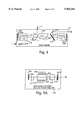
- FIG. 5A is a block diagram of an alternate amplifier pump laser
- FIG. 5B is a block diagram of an alternative amplifier pump laser having a bi-directional, ring configuration
- FIG. 5C is a block diagram of an alternative amplifier pump laser having a uni-directional, ring configuration
- FIG. 6A is a block diagram of an alternate ring-configured optical amplifier
- FIG. 6B is a block diagram of an alternate multi-pass optical amplifier.
- the present invention provides an efficient, powerful, reliable, and convenient optical amplification system. Numerous details, such as the number of diode lasers and the use of a regenerative amplifier, are provided for the sake of clarity, but it will be obvious to those skilled in the art that the invention can be practiced apart from these specific details. In other instances, details of well known equipment and processes are omitted so as not to obscure the invention.
- FIG. 1 shows an optical amplification system 100, including a seed-pulse source 110, an optical amplifier 112, and an amplifier pump laser 114.
- Seed-pulse source 110 generates seed-pulses and sends them via optical path 116 to optical amplifier 112.
- Amplifier pump laser 114 generates pump pulses which are directed along optical path 118 into amplifier 112.
- Amplifier 112 uses the optical energy of the pump pulses to amplify the seed-pulses and emits the amplified pulses along optical path 120.
- Seed-pulse source 110 includes pump laser 122 and oscillator 124.
- Pump laser 122 provides optical energy, via optical path 126, which excites oscillator 124 to emit the seed-pulses along optical path 116.
- pump laser 122 is a continuous-wave laser and oscillator 124 is a titanium-sapphire oscillator. Seed-pulse sources are well known in the art, and therefore will not be discussed in greater detail.
- FIG. 2 shows a detailed view of amplifier pump laser 114, including a first reflector 202, a Q-switch 204, a laser medium element 206, a plurality of diode lasers 208, a second reflector 210, an output coupler 212, a frequency altering device 214, and a third reflector 216.
- laser medium element 206 is a cylindrical rod of neodymium-doped yttrium-lithium-fluoride (YLF), but those skilled in the art will understand that the invention may be practiced with alternate active elements, such as erbium (Er) holmium, (Ho) or thorium (Th), or alternate carriers such as glass, vanadate, or yttrium-scandium-gallium-garnet (YSGG).
- Diode lasers 208 are disposed along the lateral surface of laser medium element 206, and when provided with electrical current emit laser light into element 206 which excites the atoms of element 206 to a metastable state. The relaxation of the excited atoms is accompanied by the emission of light of a first frequency (w), some of which travels along a folded optical path 218.
- w first frequency
- Reflectors 202 and 216 are positioned at opposite ends of optical path 218, and each respectively has a reflective surface 220 and 222 which is substantially perpendicular to an incident segment of optical path 218. Therefore, any light traveling along optical path 218 which is incident on either reflector 202 or 216 is reflected back along optical path 218.
- Reflector 210 and output coupler 212 fold optical path 218 to pass between reflectors 202 and 216, through Q-switch 204, laser medium element 206 and frequency altering device 214. As the light oscillates back and forth between reflectors 202 and 216, the growing reflected wave induces the emission of additional light into the reflected wave state, thus amplifying the reflected wave.
- Q-switch 204 is disposed in optical path 218 between reflector 202 and laser medium element 206 and selectively frustrates or permits oscillation. When oscillation is frustrated, the excited atoms are not induced to emit light, and the number of excited atoms can, therefore, be greatly increased. Then, when Q-switch 204 permits oscillation, a powerful pulse will be generated as the large number of excited atoms drop to the lower state, emitting light as they make the transition.
- Many Q-switching arrangements are known, including, but not limited to, bleachable absorbers that become transparent under illumination, rotating prisms and mirrors, mechanical choppers, ultrasonic cells, and electro-optic shutters such as Kerr or Pockels cells. The present invention contemplates the use of any such switching device.
- Frequency altering device 214 is disposed in optical path 218, between reflector 216 and output coupler 212.
- frequency altering device 214 is a lithium-triborate (LBO) doubling crystal, but those skilled in the art will understand that the invention may be practiced with alternative doubling crystals, including but not limited to beta-barium-borate (BBO), potassium-titanyl-phosphate (KTP) and potassium-dihydrogen-phosphate (KDP).
- BBO beta-barium-borate
- KTP potassium-titanyl-phosphate
- KDP potassium-dihydrogen-phosphate
- Output coupler 212 is designed to be highly reflective to the first frequency (w) but transparent to the second (2w) frequency, and therefore passes the second (2w) wave as an output pulse along optical path 118.
- the intracavity disposition of device 214 is advantageous over prior art systems which positioned the doubling crystal between the amplifier pump laser and the optical amplifier. Since the reflected (w) wave makes multiple passes through device 214, the doubling efficiency is greatly increased, resulting in an increase in output power.
- FIG. 3 shows an end view of laser medium element 206, taken along optical path 218.
- the plurality of diode lasers 208 are disposed along the circumference of medium element 206 which, except for openings through which diode lasers 208 emit their light, is surrounded by a highly reflective material 310.
- the reflective material 310 increases efficiency by insuring that the light emitted by diode lasers 208 makes several passes through medium element 206, thus increasing the opportunity for absorption.
- a suitable choice of neodymium concentration in the YLF or a suitable distribution of the pump diodes around the rod could eliminate the need for the reflective material.
- the laser beams emitted by diode lasers 208 are typically diverse, and are shown in FIG. 2 as narrow rays for the sake of clarity.
- FIG. 4 is a block diagram detailing optical amplifier 112, which includes a gain medium element 402, first and second reflectors 404 and 406, first and second Pockels cells 408 and 410, a polarizing beam splitter 412, and first and second beam directors 414 and 416.
- gain medium element 402 is a cylindrical rod of titanium-doped sapphire (Ti:Al 2 O 3 ) having a first end surface 418 and a second end surface 420, each formed by a Brewster cut.
- Reflectors 404 and 406 each have a highly reflective surface 422 and 424 respectively, and are positioned facing each other at opposite ends of gain medium element 402 with their reflective surfaces 422 and 424 perpendicular to an optical path 426 passing through both end surfaces 418 and 420 of gain medium element 402.
- First and second Pockels cells 408 and 410 are disposed in optical path 426, between gain medium element 402 and first and second reflectors 404 and 406, respectively.
- Polarizing beam splitter 412 is disposed in optical path 426 between gain medium element 402 and second Pockels cell 410.
- optical path 116 forms an angle of about 114° with optical path 426.
- the reflected seed-pulse is polarized, and optical path 116 is oriented relative to gain medium element 402 such that the polarized seed-pulse is reflected along optical path 426 toward first Pockels cell 408.
- First Pockels cell 408 selectively switches a seed-pulse into optical amplifier 112, where the pulse is amplified during several passes along optical path 426 between reflectors 404 and 406.
- the energy for the amplification that occurs in optical amplifier 112 is provided by amplifier pump laser 114.
- First beam director 414 redirects the pump light emitted from amplifier pump laser 114 along optical path 118 to impinge on first end surface 418 of gain medium element 402.
- the pump light passes through first end surface 418 and is absorbed by the atoms of gain medium element 402, exciting them to a metastable state.
- the excited atoms are induced by the oscillating seed-pulse to re-emit the absorbed light into the seed-pulse state, thereby amplifying the seed-pulse.
- second Pockels cell 410 ejects the amplified pulse by altering its polarization such that polarizing beam splitter 412 directs the pulse toward second beam director 416, which in turn directs the pulse along optical path 120 out of optical amplifier 112.
- optical switching techniques include a single Pockels cell, multiple Pockels cells, a combination of a Pockels cell and a wave plate, acousto-optic cells, Faraday isolators, and a multitude of other combinations of the foregoing.
- the invention contemplates the use of each of these and other types of switching techniques, and is limited only by the appended claims.
- amplifier 112 of the preferred embodiment of the invention has been disclosed as a linear regenerative amplifier, it will be obvious to those skilled in the art that the invention may be practiced with other types of optical amplifiers. In fact, the invention contemplates the use of other types of amplifiers, and is limited only by the appended claims.
- FIG. 5A is a block diagram of an alternate amplifier pump laser 114a characterized by a straight-line optical path 502.
- Alternate pump laser 114a includes a laser medium element 504, a plurality of diode lasers 506, a reflector 508, an output coupler 510, a Q-switch 512, and a frequency altering device 514.
- Diode lasers 506 are disposed along the lateral surface of laser medium element 504, and when provided with electrical current emit laser light into element 504 which excites the atoms of element 504 to a metastable state.
- the relaxation of the excited atoms is accompanied by the emission of light of a first frequency (w), some of which travels along optical path 502.
- Reflector 508 and output coupler 510 are positioned to face each other at opposite ends of optical path 502.
- Reflector 508 and output coupler 510 each have a reflective surface 516 and 518 respectively which is substantially perpendicular to optical path 502. Therefore, any light traveling along optical path 502 which is incident on either reflector 508 or output coupler 510 is reflected back along optical path 502. As the light oscillates back and forth between reflector 508 and output coupler 510, the growing reflected wave induces the emission of additional light into the reflected wave state, thus amplifying the reflected wave.
- Q-switch 512 is disposed in optical path 502 between reflector 508 and laser medium element 504 and selectively frustrates or permits oscillation. When oscillation is frustrated, the excited atoms are not induced to emit light, and the number of excited atoms can, therefore, be greatly increased. Then, when Q-switch 512 permits oscillation, a powerful pulse will be generated as the large number of excited atoms drop to the lower state, emitting light as they make the transition.
- Frequency altering device 514 is disposed in optical path 502, between laser medium element 504 and output coupler 510. As the light of frequency (w) emitted by laser medium element 504 travels along optical path 502 through device 514, the frequency of a portion of the beam is doubled, creating a second wave at the doubled frequency (2w).
- Output coupler 510 is designed to be highly reflective to the first frequency (w) but transparent to the second (2w) frequency, and therefore passes the second (2w) wave as an output pulse along optical path 118.
- FIG. 5B shows an alternate bi-directional, ring-configured amplifier pump laser 114b, which could be substituted for amplifier pump laser 114.
- Pump laser 114b is characterized by a triangular optical path 520, and includes a laser medium element 524, a plurality of diode lasers 526, a first beam director 528, a second beam director 530, an output coupler 532, a Q-switch 534, and a frequency altering device 536.
- Diode lasers 526 stimulate laser medium element 524 to emit light of a first frequency in both directions along optical path 520.
- Q-switch 534 pulses laser 114b, and frequency altering device 536 doubles the frequency of a portion of the light passing therethrough.
- Beam directors 528 and 530 are disposed at two of the vertices of optical path 520 to direct light incident from one leg of optical path 520 along the adjacent leg.
- Output coupler 532 is disposed at the remaining vertex of optical path 520 and is designed to reflect light of the first frequency and transmit light of the doubled frequency as output beams along optical paths 118 and 538.
- optical path 520 need not be triangular. With the addition of an appropriate number of beam directors optical path 520 could be shaped as any multi-sided polygon. Further, additional laser medium elements may be disposed in one or more of the additional legs to create a more powerful multi-element laser. All such modifications are considered to be within the scope of the present invention.
- the dual output is a result of the bi-directional operation of laser 114b.
- Light traveling along optical path 520 in a clockwise direction will be emitted along optical path 118, whereas light traveling along optical path 520 in a counter-clockwise direction will be emitted along optical path 538.
- Bi-directional operation is desirable when two output beams are required. When only one output beam is required, the second beam results in wasted power, and uni-directional operation is preferred.
- FIG. 5C shows an alternate uni-directional, ring-configured amplifier pump laser 114c, which could be substituted for amplifier pump laser 114.
- Ring laser 114c is substantially identical to ring laser 114b described above, but includes an additional uni-directional device (optical diode) 550.
- optical diodes include a Faraday rotator, an optically active crystal and a Brewster plate.
- Faraday rotators rotate the polarization of a beam in a direction of rotation that is not dependent on the direction of travel of the wave, but the direction of rotation by the optical crystal does depend on the direction of travel of the wave. Therefore, in one direction the effect of the two components combine to produce a net rotation, but in the other direction they offset, producing no net rotation.
- the Brewster plate then selectively introduces a loss in the direction undergoing a net rotation, frustrating oscillation in that direction.
- Other means for encouraging unidirectional oscillation are known to those skilled in the art, and are considered to be within the scope of the
- FIG. 6A shows an alternate ring-configured, regenerative optical amplifier characterized by a rectangular optical path 602 and including four beam directors 604, 606, 608, and 610, a gain media element 612, a Pockels cell 614 and a polarizing beam splitter 616.
- Beam directors 604, 606, 608, and 610 are each disposed at one of the vertices of optical path 602, to redirect light incident from one leg of optical path 602 along the adjacent leg.
- Gain element 612 has a first end surface 618 and a second end surface 620, and is disposed between beam directors 604 and 610 such that optical path 602 passes through first and second end surfaces 618 and 620 of gain element 612.
- Pockels cell 614 and polarizing beam splitter 616 are disposed in optical path 602 between beam directors 606 and 608, with beam splitting polarizer 616 nearer beam director 606.
- a polarized seed-pulse enters amplifier 600 via optical path 622, and is reflected along optical path 602 toward beam director 610 by the second end surface 620 of gain element 612.
- the seed-pulse travels counter-clockwise around optical path 602, first being reflected by beam directors 610 and 608, then passing through Pockels cell 614 which alters its polarization and, thus, it passes through polarizing beam splitter 616, then being reflected by beam directors 606 and 604, and finally passing through gain element 612.
- the seed-pulse is amplified as it repeats the loop around optical path 602.
- the power for amplification is provided by a pump laser whose output beam enters amplifier 600 via optical path 626.
- the pump beam passes through first end surface 618 of gain element 612 where it is absorbed by the active atoms of the gain medium, exciting them to a metastable state.
- the oscillating seed-pulse induces the excited atoms to re-emit the absorbed light into the seed-pulse state, thereby amplifying the seed-pulse.
- Pockels cell 614 After a number of amplifying passes around optical path 602, Pockels cell 614 ejects the pulse by altering its polarization such that polarizing beam splitter 616 directs the pulse along optical path 624 out of optical amplifier 600.
- polarizing beam splitter 616 directs the pulse along optical path 624 out of optical amplifier 600.
- FIG. 6B shows an optional multi-pass optical amplifier 650, characterized by a "bow tie" shaped optical path 651, including a gain element 652 and four beam directors 654, 656, 658, and 660.
- a seed-pulse enters amplifier 650 along optical path 662 and passes through gain element 652 and proceeds along optical path 651 toward beam director 654.
- Beam director 654 redirects the pulse along the next leg of optical path 651 toward beam director 656, which in turn redirects the pulse back through gain element 652 and toward beam director 658.
- Beam director 658 then directs the pulse toward beam director 660, which in turn directs the pulse through gain element 652 a third time and out of amplifier 650 via optical path 664.
- the pulse is amplified each time it passes through gain element 652, with power provided by a pump laser beam.
- an amplifier of this type could consist simply of a gain element and a pumping means, with the beam making only one pass (although this is not technically a multi-pass amplifier) through the element.
- a large number of beam directors could be arranged around the gain element, greatly increasing the number of passes by the beam through the gain element.
Abstract
An efficient, powerful and reliable system for amplifying optical pulses. Seed-pulses are generated by a seed-pulse source and are transmitted to an optical amplifier for amplification. The power for the amplification is provided by a Q-switched, diode-pumped, intracavity-doubled pump laser.
Description
This application is a continuation of application Ser. No. 08/787,991, filed on Jan. 23, 1997, which issued as U.S. Pat. No. 5,790,303 on Aug. 4, 1998.
1. Field of the Invention
This invention relates generally to the field of lasers, and more particularly to lasers for pumping optical amplifiers.
2. Description of the Background Art
Known amplifier systems employ a source laser, an amplifier, and a pump source to transfer energy to the amplifying medium, to generate amplified laser light. The source laser emits a beam of laser light that is amplified as it passes through the amplifier. The energy for the amplification is provided to the amplifier by the pump source, which is typically a laser. A pump laser generally includes a laser medium element, positioned between a high reflector and an output coupler, and a pumping means. The pumping means excites the atoms of the medium element into a metastable state. The relaxation of the excited atoms is accompanied by the emission of light, which is reflected back and fourth between the high reflector and the output coupler, and the growing reflected wave induces the emission of additional light into the reflected wave state. As the wave continues to grow, the output coupler allows a portion of the reflected light to pass as the output beam of the pump laser.
It is obviously desirable that the pump laser be efficient, powerful, reliable, and convenient to set up and operate, but often there is tension between these various design objectives. For example, diode lasers provide a very efficient pumping means and are more durable than lamps, but the output energy of known diode-pumped lasers has been too low for them to function effectively as amplifier pumping lasers. Further, some prior diode-pumped systems require that the pitch of the diode emitters be carefully matched and aligned to the optical path within the media element, reducing convenience of assembly.
More powerful pump lasers exist, but in each case the power increase comes at the expense of one of the other design objectives. For example, more power can be obtained by using gas filled lamps to excite the pump laser lasing medium, but these systems are less efficient, less reliable, and less robust. Additionally, such lasers generally have significant cooling requirements and require a special power service, as opposed to a standard 110V AC outlet.
Thus, there is a need for a laser amplifier system capable of producing an output that is orders of magnitude higher in energy than known diode-pumped systems. It is also desirable that the amplifier system be efficient, reliable, and convenient to set up and operate.
The present invention is an efficient, powerful and reliable optical amplification system. Seed-pulses are generated by a seed-pulse source and are transferred to an optical amplifier for amplification. The power for the amplification is provided by a Q-switched, diode-pumped, intracavity-doubled amplifier pump laser.
One embodiment of the amplifier pump laser includes a laser medium element that is pumped by a plurality of diode lasers to emit a beam of light at a first frequency along an optical path passing through the element. The pump laser also includes at least one reflector and an output coupler, for redirecting the beam along the optical path to establish an optical resonator. A Q-switch is disposed in the optical path to selectively frustrate or permit optical resonance, thereby enabling the laser to produce high-power output pulses, as opposed to low-power, continuous output. The output power of the pump laser is further enhanced by including a doubling crystal within the optical cavity. The doubling crystal is disposed in the optical path and converts a portion of the original oscillating wave to a new wave having twice the frequency of the original. The output coupler is highly reflective to the original frequency, but highly transmissive to the doubled frequency, and, therefore, passes the doubled frequency wave as output.
There are several specific embodiments of the amplifier pump laser of the present invention. One embodiment is characterized by a beam that is directed between two reflectors, along a folded optical path, by a beam director and an output coupler. Another embodiment is characterized by a straight optical path between one reflector and the output coupler. Finally, there are uni-directional and bi-directional ring configured embodiments.
One embodiment of the optical amplifier of the present invention is a regenerative amplifier which includes a gain medium element within an optically resonant cavity, a capturing means for switching seed-pulses into the cavity, and an ejecting means for switching amplified pulses out of the cavity. The output beam of the amplifier pump laser excites the gain medium, which amplifies the seed-pulse as it oscillates within the cavity. After amplification, the ejecting means switches the amplified pulse out of the cavity as the amplification system output.
Other embodiments of the optical amplifier include a ring configured regenerative amplifier and a multi-pass "bow-tie" amplifier.
FIG. 1 is a block diagram of the preferred optical amplification system of the present invention;
FIG. 2 is a block diagram of the diode-pumped, Q-switched, intracavity-doubled pump laser of FIG. 1;
FIG. 3 shows an end view of the laser medium element of FIG. 2;
FIG. 4 is a block diagram of the optical amplifier of FIG. 1;
FIG. 5A is a block diagram of an alternate amplifier pump laser;
FIG. 5B is a block diagram of an alternative amplifier pump laser having a bi-directional, ring configuration;
FIG. 5C is a block diagram of an alternative amplifier pump laser having a uni-directional, ring configuration;
FIG. 6A is a block diagram of an alternate ring-configured optical amplifier; and
FIG. 6B is a block diagram of an alternate multi-pass optical amplifier.
The present invention provides an efficient, powerful, reliable, and convenient optical amplification system. Numerous details, such as the number of diode lasers and the use of a regenerative amplifier, are provided for the sake of clarity, but it will be obvious to those skilled in the art that the invention can be practiced apart from these specific details. In other instances, details of well known equipment and processes are omitted so as not to obscure the invention.
FIG. 1 shows an optical amplification system 100, including a seed-pulse source 110, an optical amplifier 112, and an amplifier pump laser 114. Seed-pulse source 110 generates seed-pulses and sends them via optical path 116 to optical amplifier 112. Amplifier pump laser 114 generates pump pulses which are directed along optical path 118 into amplifier 112. Amplifier 112 uses the optical energy of the pump pulses to amplify the seed-pulses and emits the amplified pulses along optical path 120.
Seed-pulse source 110 includes pump laser 122 and oscillator 124. Pump laser 122 provides optical energy, via optical path 126, which excites oscillator 124 to emit the seed-pulses along optical path 116. In the preferred embodiment, pump laser 122 is a continuous-wave laser and oscillator 124 is a titanium-sapphire oscillator. Seed-pulse sources are well known in the art, and therefore will not be discussed in greater detail.
FIG. 2 shows a detailed view of amplifier pump laser 114, including a first reflector 202, a Q-switch 204, a laser medium element 206, a plurality of diode lasers 208, a second reflector 210, an output coupler 212, a frequency altering device 214, and a third reflector 216. In the preferred embodiment, laser medium element 206 is a cylindrical rod of neodymium-doped yttrium-lithium-fluoride (YLF), but those skilled in the art will understand that the invention may be practiced with alternate active elements, such as erbium (Er) holmium, (Ho) or thorium (Th), or alternate carriers such as glass, vanadate, or yttrium-scandium-gallium-garnet (YSGG). Diode lasers 208 are disposed along the lateral surface of laser medium element 206, and when provided with electrical current emit laser light into element 206 which excites the atoms of element 206 to a metastable state. The relaxation of the excited atoms is accompanied by the emission of light of a first frequency (w), some of which travels along a folded optical path 218.
Q-switch 204 is disposed in optical path 218 between reflector 202 and laser medium element 206 and selectively frustrates or permits oscillation. When oscillation is frustrated, the excited atoms are not induced to emit light, and the number of excited atoms can, therefore, be greatly increased. Then, when Q-switch 204 permits oscillation, a powerful pulse will be generated as the large number of excited atoms drop to the lower state, emitting light as they make the transition. Many Q-switching arrangements are known, including, but not limited to, bleachable absorbers that become transparent under illumination, rotating prisms and mirrors, mechanical choppers, ultrasonic cells, and electro-optic shutters such as Kerr or Pockels cells. The present invention contemplates the use of any such switching device.
FIG. 3 shows an end view of laser medium element 206, taken along optical path 218. The plurality of diode lasers 208 are disposed along the circumference of medium element 206 which, except for openings through which diode lasers 208 emit their light, is surrounded by a highly reflective material 310. The reflective material 310 increases efficiency by insuring that the light emitted by diode lasers 208 makes several passes through medium element 206, thus increasing the opportunity for absorption. Those skilled in the art will understand that a suitable choice of neodymium concentration in the YLF or a suitable distribution of the pump diodes around the rod could eliminate the need for the reflective material. Those skilled in the art will also understand that the laser beams emitted by diode lasers 208 are typically diverse, and are shown in FIG. 2 as narrow rays for the sake of clarity.
FIG. 4 is a block diagram detailing optical amplifier 112, which includes a gain medium element 402, first and second reflectors 404 and 406, first and second Pockels cells 408 and 410, a polarizing beam splitter 412, and first and second beam directors 414 and 416. In the preferred embodiment, gain medium element 402 is a cylindrical rod of titanium-doped sapphire (Ti:Al2 O3) having a first end surface 418 and a second end surface 420, each formed by a Brewster cut. Reflectors 404 and 406 each have a highly reflective surface 422 and 424 respectively, and are positioned facing each other at opposite ends of gain medium element 402 with their reflective surfaces 422 and 424 perpendicular to an optical path 426 passing through both end surfaces 418 and 420 of gain medium element 402. First and second Pockels cells 408 and 410 are disposed in optical path 426, between gain medium element 402 and first and second reflectors 404 and 406, respectively. Polarizing beam splitter 412 is disposed in optical path 426 between gain medium element 402 and second Pockels cell 410.
During operation, seed-pulses emitted by seed-pulse source 110 along optical path 116 impinge on first end surface 418 of gain medium element 402. Although the angle appears smaller in FIG. 4 for purposes of illustration, optical path 116 forms an angle of about 114° with optical path 426. The reflected seed-pulse is polarized, and optical path 116 is oriented relative to gain medium element 402 such that the polarized seed-pulse is reflected along optical path 426 toward first Pockels cell 408. First Pockels cell 408 selectively switches a seed-pulse into optical amplifier 112, where the pulse is amplified during several passes along optical path 426 between reflectors 404 and 406.
The energy for the amplification that occurs in optical amplifier 112 is provided by amplifier pump laser 114. First beam director 414 redirects the pump light emitted from amplifier pump laser 114 along optical path 118 to impinge on first end surface 418 of gain medium element 402. The pump light passes through first end surface 418 and is absorbed by the atoms of gain medium element 402, exciting them to a metastable state. The excited atoms are induced by the oscillating seed-pulse to re-emit the absorbed light into the seed-pulse state, thereby amplifying the seed-pulse. After a number of passes between first and second reflectors 404 and 406 along optical path 426, second Pockels cell 410 ejects the amplified pulse by altering its polarization such that polarizing beam splitter 412 directs the pulse toward second beam director 416, which in turn directs the pulse along optical path 120 out of optical amplifier 112. Those skilled in the art will understand that there are many optical switching techniques that can be used to switch pulses into and out of the regenerative amplifier resonator. These include a single Pockels cell, multiple Pockels cells, a combination of a Pockels cell and a wave plate, acousto-optic cells, Faraday isolators, and a multitude of other combinations of the foregoing. The invention contemplates the use of each of these and other types of switching techniques, and is limited only by the appended claims.
While amplifier 112 of the preferred embodiment of the invention has been disclosed as a linear regenerative amplifier, it will be obvious to those skilled in the art that the invention may be practiced with other types of optical amplifiers. In fact, the invention contemplates the use of other types of amplifiers, and is limited only by the appended claims.
FIG. 5A is a block diagram of an alternate amplifier pump laser 114a characterized by a straight-line optical path 502. Alternate pump laser 114a includes a laser medium element 504, a plurality of diode lasers 506, a reflector 508, an output coupler 510, a Q-switch 512, and a frequency altering device 514. Diode lasers 506 are disposed along the lateral surface of laser medium element 504, and when provided with electrical current emit laser light into element 504 which excites the atoms of element 504 to a metastable state. The relaxation of the excited atoms is accompanied by the emission of light of a first frequency (w), some of which travels along optical path 502.
Q-switch 512 is disposed in optical path 502 between reflector 508 and laser medium element 504 and selectively frustrates or permits oscillation. When oscillation is frustrated, the excited atoms are not induced to emit light, and the number of excited atoms can, therefore, be greatly increased. Then, when Q-switch 512 permits oscillation, a powerful pulse will be generated as the large number of excited atoms drop to the lower state, emitting light as they make the transition.
FIG. 5B shows an alternate bi-directional, ring-configured amplifier pump laser 114b, which could be substituted for amplifier pump laser 114. Pump laser 114b is characterized by a triangular optical path 520, and includes a laser medium element 524, a plurality of diode lasers 526, a first beam director 528, a second beam director 530, an output coupler 532, a Q-switch 534, and a frequency altering device 536. Diode lasers 526 stimulate laser medium element 524 to emit light of a first frequency in both directions along optical path 520. As described above, Q-switch 534 pulses laser 114b, and frequency altering device 536 doubles the frequency of a portion of the light passing therethrough. Beam directors 528 and 530 are disposed at two of the vertices of optical path 520 to direct light incident from one leg of optical path 520 along the adjacent leg. Output coupler 532 is disposed at the remaining vertex of optical path 520 and is designed to reflect light of the first frequency and transmit light of the doubled frequency as output beams along optical paths 118 and 538.
It will be clear to one skilled in the art that optical path 520 need not be triangular. With the addition of an appropriate number of beam directors optical path 520 could be shaped as any multi-sided polygon. Further, additional laser medium elements may be disposed in one or more of the additional legs to create a more powerful multi-element laser. All such modifications are considered to be within the scope of the present invention.
The dual output is a result of the bi-directional operation of laser 114b. Light traveling along optical path 520 in a clockwise direction will be emitted along optical path 118, whereas light traveling along optical path 520 in a counter-clockwise direction will be emitted along optical path 538. Bi-directional operation is desirable when two output beams are required. When only one output beam is required, the second beam results in wasted power, and uni-directional operation is preferred.
FIG. 5C shows an alternate uni-directional, ring-configured amplifier pump laser 114c, which could be substituted for amplifier pump laser 114. Ring laser 114c is substantially identical to ring laser 114b described above, but includes an additional uni-directional device (optical diode) 550. Typically, optical diodes include a Faraday rotator, an optically active crystal and a Brewster plate. Faraday rotators rotate the polarization of a beam in a direction of rotation that is not dependent on the direction of travel of the wave, but the direction of rotation by the optical crystal does depend on the direction of travel of the wave. Therefore, in one direction the effect of the two components combine to produce a net rotation, but in the other direction they offset, producing no net rotation. The Brewster plate then selectively introduces a loss in the direction undergoing a net rotation, frustrating oscillation in that direction. Other means for encouraging unidirectional oscillation are known to those skilled in the art, and are considered to be within the scope of the invention.
FIG. 6A shows an alternate ring-configured, regenerative optical amplifier characterized by a rectangular optical path 602 and including four beam directors 604, 606, 608, and 610, a gain media element 612, a Pockels cell 614 and a polarizing beam splitter 616. Beam directors 604, 606, 608, and 610 are each disposed at one of the vertices of optical path 602, to redirect light incident from one leg of optical path 602 along the adjacent leg. Gain element 612 has a first end surface 618 and a second end surface 620, and is disposed between beam directors 604 and 610 such that optical path 602 passes through first and second end surfaces 618 and 620 of gain element 612. Pockels cell 614 and polarizing beam splitter 616 are disposed in optical path 602 between beam directors 606 and 608, with beam splitting polarizer 616 nearer beam director 606.
A polarized seed-pulse enters amplifier 600 via optical path 622, and is reflected along optical path 602 toward beam director 610 by the second end surface 620 of gain element 612. The seed-pulse travels counter-clockwise around optical path 602, first being reflected by beam directors 610 and 608, then passing through Pockels cell 614 which alters its polarization and, thus, it passes through polarizing beam splitter 616, then being reflected by beam directors 606 and 604, and finally passing through gain element 612.
The seed-pulse is amplified as it repeats the loop around optical path 602. The power for amplification is provided by a pump laser whose output beam enters amplifier 600 via optical path 626. The pump beam passes through first end surface 618 of gain element 612 where it is absorbed by the active atoms of the gain medium, exciting them to a metastable state. The oscillating seed-pulse induces the excited atoms to re-emit the absorbed light into the seed-pulse state, thereby amplifying the seed-pulse. After a number of amplifying passes around optical path 602, Pockels cell 614 ejects the pulse by altering its polarization such that polarizing beam splitter 616 directs the pulse along optical path 624 out of optical amplifier 600. Those skilled in the art will recognize that there many techniques, for example those described above, for switching a pulse into and out of a regenerative amplifier, and the present invention contemplates the use of any such switching technique.
FIG. 6B shows an optional multi-pass optical amplifier 650, characterized by a "bow tie" shaped optical path 651, including a gain element 652 and four beam directors 654, 656, 658, and 660. A seed-pulse enters amplifier 650 along optical path 662 and passes through gain element 652 and proceeds along optical path 651 toward beam director 654. Beam director 654 redirects the pulse along the next leg of optical path 651 toward beam director 656, which in turn redirects the pulse back through gain element 652 and toward beam director 658. Beam director 658 then directs the pulse toward beam director 660, which in turn directs the pulse through gain element 652 a third time and out of amplifier 650 via optical path 664. The pulse is amplified each time it passes through gain element 652, with power provided by a pump laser beam.
Those skilled in the art will recognize that there are many variations on this type of amplifier. In its simplest form, an amplifier of this type could consist simply of a gain element and a pumping means, with the beam making only one pass (although this is not technically a multi-pass amplifier) through the element. At the other extreme, a large number of beam directors could be arranged around the gain element, greatly increasing the number of passes by the beam through the gain element.
The present invention has been disclosed with reference to a preferred embodiment and several alternate embodiments. Specific details have been set forth, such as the number of medium elements in a pump laser or amplifier, specific beam paths, and methods for switching pulses into and out of an amplifier. Those skilled in the art will understand that the invention may be practiced apart from the specific details set forth herein.
Claims (19)
1. A method for amplifying an optical pulse in a laser comprising the steps of:
generating a pulsed light in a Q-switched, amplifier pump laser;
directing the pulsed light to an optical gain element comprising a medium of optically responsive atoms;
exciting the atoms to a metastable state using the pulsed light; and
directing a seed pulse at the gain element of an optical amplifier,
thereby causing the excited atoms to emit an amplified optical pulse.
2. The method of claim 1 wherein said step of generating a pulsed light includes altering a frequency of said light with a frequency altering device.
3. The method of claim 2 wherein said step of altering the frequency of said light utilizes a frequency doubling crystal.
4. The method of claim 2 further comprising:
disposing intracavity said frequency altering device.
5. The method of claim 2 wherein said step of generating a pulsed light includes providing output coupler means.
6. A method for generating and amplifying an optical pulse comprising the steps of:
exciting atoms in a laser medium;
causing oscillation in said laser medium using a Q-switch disposed along an optical path to produce laser light along said optical path;
altering the frequency of at least some of said laser light along said optical path;
selectively releasing laser light having the altered frequency from said optical path;
receiving the selectively released laser light at an optical amplifier to provide optical energy to the optical amplifier; and
receiving a seed-pulse at the optical amplifier to cause the optical amplifier to emit an amplified optical pulse.
7. The method of claim 6 wherein said step of altering the frequency is performed by a frequency doubling crystal.
8. The method of claim 7 wherein said frequency doubling crystal is intracavity disposed.
9. The method of claim 6 wherein said step of selectively releasing laser light is performed by an optical coupler.
10. The method of claim 6 wherein the steps of receiving the selectively released laser light and receiving a seed-pulse are performed by a gain medium element.
11. A system for amplifying optical pulses comprising:
a seed-pulse source for producing optical seed-pulses;
an optical amplifier disposed to receive said seed-pulses from said seed-pulse source, for receiving and amplifying said seed-pulses and for outputting amplified seed-pulses; and
an amplifier pumping laser for providing optical energy to said optical amplifier for the amplification of said seed-pulses, said amplifier pumping laser including an intracavity frequency altering device and a switching means for selectively frustrating or allowing optical resonance,
thereby enabling said amplifier pumping laser to emit pulses of laser light.
12. The system of claim 11 wherein said switching means comprises a Q-switch.
13. The system of claim 11 wherein said frequency altering device comprises a frequency doubling crystal.
14. A system for amplifying optical pulses, comprising:
a lasing material;
switching means for selectively frustrating or allowing optical resonance in said lasing material;
a frequency altering device for altering the frequency of light emitted from said lasing material;
a seed pulse source for producing optical seed-pulses;
an optical amplifier disposed to receive the optical seed-pulses from the seed pulse source and to receive light emitted from the frequency altering device to amplify the optical seed-pulses with optical energy from the light emitted from the frequency altering device.
15. The pumping laser of claim 14 wherein said switching means comprises a Q-switch.
16. The pumping laser of claim 14 wherein said frequency altering device comprises a frequency doubling crystal.
17. A system for amplifying optical pulses, comprising:
a seed pulse source for producing optical seed-pulses;
an optical amplifier disposed to receive the seed-pulses from the seed-pulse source, for receiving and amplifying the seed pulses and for outputting amplified seed-pulses; and
an amplifier pumping laser for providing optical energy to the optical amplifier for the amplification of the seed-pulses, the amplifier pumping laser including a frequency altering device and a switching device for selectively frustrating or allowing optical resonance, thereby enabling the amplifier pumping laser to emit pulses of laser light.
18. A system for amplifying optical pulses, comprising:
a seed pulse source for producing optical seed-pulses;
an optical amplifier disposed to receive the seed-pulses from the seed-pulse source, for receiving and amplifying the seed pulses and for outputting amplified seed-pulses; and
an amplifier pumping laser for providing optical energy to the optical amplifier for the amplification of the seed-pulses, the amplifier pumping laser including an intracavity frequency altering device and a switching device for selectively frustrating or allowing optical resonance, thereby enabling the amplifier pumping laser to emit pulses of laser light.
19. A system for amplifying optical pulses, comprising:
an amplifier pumping laser for providing optical energy to an optical amplifier for the amplification of seed-pulses;
the amplifier pumping laser including an intracavity frequency altering device and a switching device for selectively frustrating or allowing optical resonance, thereby enabling the amplifier pumping laser to emit pulses of laser light.
Priority Applications (2)
| Application Number | Priority Date | Filing Date | Title |
|---|---|---|---|
| US09/124,593 US5963363A (en) | 1997-01-23 | 1998-07-29 | System and method for amplifying an optical pulse and pumping laser therefor |
| US10/224,158 USRE42499E1 (en) | 1997-01-23 | 2002-08-19 | System and method for amplifying an optical pulse and pumping laser therefor |
Applications Claiming Priority (2)
| Application Number | Priority Date | Filing Date | Title |
|---|---|---|---|
| US08/787,991 US5790303A (en) | 1997-01-23 | 1997-01-23 | System for amplifying an optical pulse using a diode-pumped, Q-switched, intracavity-doubled laser to pump an optical amplifier |
| US09/124,593 US5963363A (en) | 1997-01-23 | 1998-07-29 | System and method for amplifying an optical pulse and pumping laser therefor |
Related Parent Applications (1)
| Application Number | Title | Priority Date | Filing Date |
|---|---|---|---|
| US08/787,991 Continuation US5790303A (en) | 1997-01-23 | 1997-01-23 | System for amplifying an optical pulse using a diode-pumped, Q-switched, intracavity-doubled laser to pump an optical amplifier |
Related Child Applications (1)
| Application Number | Title | Priority Date | Filing Date |
|---|---|---|---|
| US10/224,158 Reissue USRE42499E1 (en) | 1997-01-23 | 2002-08-19 | System and method for amplifying an optical pulse and pumping laser therefor |
Publications (1)
| Publication Number | Publication Date |
|---|---|
| US5963363A true US5963363A (en) | 1999-10-05 |
Family
ID=25143115
Family Applications (3)
| Application Number | Title | Priority Date | Filing Date |
|---|---|---|---|
| US08/787,991 Expired - Lifetime US5790303A (en) | 1997-01-23 | 1997-01-23 | System for amplifying an optical pulse using a diode-pumped, Q-switched, intracavity-doubled laser to pump an optical amplifier |
| US09/124,593 Ceased US5963363A (en) | 1997-01-23 | 1998-07-29 | System and method for amplifying an optical pulse and pumping laser therefor |
| US10/224,158 Expired - Lifetime USRE42499E1 (en) | 1997-01-23 | 2002-08-19 | System and method for amplifying an optical pulse and pumping laser therefor |
Family Applications Before (1)
| Application Number | Title | Priority Date | Filing Date |
|---|---|---|---|
| US08/787,991 Expired - Lifetime US5790303A (en) | 1997-01-23 | 1997-01-23 | System for amplifying an optical pulse using a diode-pumped, Q-switched, intracavity-doubled laser to pump an optical amplifier |
Family Applications After (1)
| Application Number | Title | Priority Date | Filing Date |
|---|---|---|---|
| US10/224,158 Expired - Lifetime USRE42499E1 (en) | 1997-01-23 | 2002-08-19 | System and method for amplifying an optical pulse and pumping laser therefor |
Country Status (1)
| Country | Link |
|---|---|
| US (3) | US5790303A (en) |
Cited By (17)
| Publication number | Priority date | Publication date | Assignee | Title |
|---|---|---|---|---|
| US6404540B1 (en) | 1999-06-23 | 2002-06-11 | Samsung Electronics Co., Ltd. | L-band optical fiber amplifier using seed beam |
| US6470113B1 (en) | 1999-07-21 | 2002-10-22 | Samsung Electronics Co., Ltd. | Broadband light source using seed-beam |
| US20030086154A1 (en) * | 2000-07-28 | 2003-05-08 | Feillens Yannick G. | Method of amplifying optical signals using doped materials with extremely broad bandwidths |
| US20030147443A1 (en) * | 2002-02-02 | 2003-08-07 | Backus Sterling J. | Ultrashort pulse amplification in cryogenically cooled amplifiers |
| US6608852B2 (en) | 2000-08-25 | 2003-08-19 | Lameda Physik Ag | Gain module for diode-pumped solid state laser and amplifier |
| US6614584B1 (en) | 2000-02-25 | 2003-09-02 | Lambda Physik Ag | Laser frequency converter with automatic phase matching adjustment |
| WO2003100928A1 (en) * | 2002-05-28 | 2003-12-04 | Thales | High power laser amplification system |
| US20040022280A1 (en) * | 2002-03-11 | 2004-02-05 | Ming Lai | Integrated laser oscillator-amplifier system |
| US20040213837A1 (en) * | 2002-08-05 | 2004-10-28 | Sankaram Mantripragada | Oil-core compositions for the sustained release of hydrophobic drugs |
| US7003005B1 (en) | 2003-04-03 | 2006-02-21 | Ming Lai | Simplified laser oscillator-amplifier system |
| US20060171439A1 (en) * | 2002-11-05 | 2006-08-03 | Govorkov Sergei V | Master oscillator - power amplifier excimer laser system |
| US20080112041A1 (en) * | 2006-11-15 | 2008-05-15 | David Clubley | First-pulse suppression in a regenerative amplifier |
| US20090003402A1 (en) * | 2007-06-29 | 2009-01-01 | Joris Van Nunen | Semiconductor-laser pumped Ti:sapphire laser |
| US20090103172A1 (en) * | 2007-10-22 | 2009-04-23 | David Clubley | Repetitively pulsed laser and amplifier with dual resonator for pulse-energy management |
| US20090304040A1 (en) * | 2005-12-28 | 2009-12-10 | Ram Oron | Diode-pumped cavity |
| USRE42499E1 (en) | 1997-01-23 | 2011-06-28 | Coherent, Inc. | System and method for amplifying an optical pulse and pumping laser therefor |
| WO2014074136A1 (en) * | 2012-11-08 | 2014-05-15 | Massachusetts Institute Of Technology | Continuous-wave organic dye lasers and methods |
Families Citing this family (22)
| Publication number | Priority date | Publication date | Assignee | Title |
|---|---|---|---|---|
| US6021154A (en) * | 1997-11-21 | 2000-02-01 | General Electric Company | Laser shock peening method and reflective laser beam homogenizer |
| US6122097A (en) * | 1998-04-16 | 2000-09-19 | Positive Light, Inc. | System and method for amplifying an optical pulse using a diode-pumped, Q-switched, extracavity frequency-doubled laser to pump an optical amplifier |
| US6028516A (en) * | 1998-10-01 | 2000-02-22 | Murphey; James D. | Trigger circuit |
| US6483859B1 (en) | 1999-06-24 | 2002-11-19 | Lockheed Martin Corporation | System and method for high-speed laser detection of ultrasound |
| US7286241B2 (en) * | 1999-06-24 | 2007-10-23 | Lockheed Martin Corporation | System and method for high-speed laser detection of ultrasound |
| US6999491B2 (en) | 1999-10-15 | 2006-02-14 | Jmar Research, Inc. | High intensity and high power solid state laser amplifying system and method |
| US6566645B1 (en) | 2000-12-19 | 2003-05-20 | James D. Murphey | Remote system trigger circuit |
| US6714307B2 (en) | 2001-10-16 | 2004-03-30 | Zygo Corporation | Measurement of complex surface shapes using a spherical wavefront |
| US7016107B2 (en) * | 2004-01-20 | 2006-03-21 | Spectra Physics, Inc. | Low-gain regenerative amplifier system |
| US7885309B2 (en) * | 2005-11-01 | 2011-02-08 | Cymer, Inc. | Laser system |
| US7643529B2 (en) | 2005-11-01 | 2010-01-05 | Cymer, Inc. | Laser system |
| US20090296758A1 (en) * | 2005-11-01 | 2009-12-03 | Cymer, Inc. | Laser system |
| US7522642B2 (en) * | 2006-03-29 | 2009-04-21 | Amo Development Llc | Method and system for laser amplification using a dual crystal Pockels cell |
| JP4523978B2 (en) * | 2008-03-28 | 2010-08-11 | 株式会社日立製作所 | Engine system |
| US20100272135A1 (en) * | 2009-04-28 | 2010-10-28 | Dmitri Vladislavovich Kuksenkov | Self-Seeded Wavelength Conversion |
| US8670175B2 (en) * | 2009-09-04 | 2014-03-11 | Lawrence Livermore National Security, Llc | Method and system for compact and efficient high energy pulsed laser amplifier |
| US8908737B2 (en) | 2011-04-04 | 2014-12-09 | Coherent, Inc. | Transition-metal-doped thin-disk laser |
| US9172467B2 (en) * | 2012-04-18 | 2015-10-27 | Infinera Corporation | Raman pump circuit |
| EP2907203A1 (en) * | 2012-10-09 | 2015-08-19 | Fraunhofer-Gesellschaft zur Förderung der angewandten Forschung e.V. | Optical enhancement resonator |
| US9246303B1 (en) * | 2014-10-31 | 2016-01-26 | Raytheon Company | Method and apparatus for temporally concentrating pump power to support generation of high peak-power pulse bursts or other time-varying laser output waveforms |
| US10852432B2 (en) * | 2016-11-15 | 2020-12-01 | Bae Systems Information And Electronic Systems Integration Inc. | Dual mode laser target designator/rangefinder with an optical parametric oscillator-optical parametric amplifier (OPO-OPA) converter |
| GB2562236A (en) | 2017-05-08 | 2018-11-14 | Uab Mgf Sviesos Konversija | Device and method for generation of high repetition rate laser pulse bursts |
Citations (4)
| Publication number | Priority date | Publication date | Assignee | Title |
|---|---|---|---|---|
| US5673281A (en) * | 1996-04-20 | 1997-09-30 | Board Of Trustees Of The Leland Stanford Junior University | Solid state system for frequency conversion using raman-active media and non-linear media |
| US5687186A (en) * | 1996-05-07 | 1997-11-11 | Hughes Electronics | Eyesafe laser transmitter with single resonator cavity for both pump laser and optical parametric oscillator |
| US5790303A (en) * | 1997-01-23 | 1998-08-04 | Positive Light, Inc. | System for amplifying an optical pulse using a diode-pumped, Q-switched, intracavity-doubled laser to pump an optical amplifier |
| US5805622A (en) * | 1994-01-24 | 1998-09-08 | Medizinisches Laserzentrum Lubeck Gmbh | Apparatus for the generation of laser pulses in the US-time range |
Family Cites Families (59)
| Publication number | Priority date | Publication date | Assignee | Title |
|---|---|---|---|---|
| US3883752A (en) | 1966-12-09 | 1975-05-13 | Nat Res Dev | Optical material |
| US3731110A (en) | 1971-07-12 | 1973-05-01 | Laser system for producing wavelength-tunable optical radiation | |
| US3914709A (en) * | 1973-05-14 | 1975-10-21 | Jersey Nuclear Avco Isotopes | Apparatus for lengthening laser output pulse duration |
| US4191928A (en) | 1978-01-11 | 1980-03-04 | The United States Of America As Represented By The United States Department Of Energy | Laser system using regenerative amplifier |
| US4227159A (en) | 1978-01-24 | 1980-10-07 | Allied Chemical Corporation | Common-resonator pre-locked laser |
| US4764731A (en) | 1981-10-13 | 1988-08-16 | The United States Of America As Represented By The Secretary Of The Navy | Light-induced unidirectional light amplifier |
| US4764739A (en) | 1981-10-13 | 1988-08-16 | The United States Of America As Represented By The Secretary Of The Navy | Light-induced unidirectional light switch |
| US4603940A (en) | 1983-08-30 | 1986-08-05 | Board Of Trustees Of The Leland Stanford Junior University | Fiber optic dye amplifier |
| US4896119A (en) * | 1984-06-07 | 1990-01-23 | The University Of Rochester | CW pumper CW pumped variable repetition rate regenerative laser amplifier system |
| US4653056A (en) | 1985-05-01 | 1987-03-24 | Spectra-Physics, Inc. | Nd-YAG laser |
| US4908832A (en) | 1985-05-01 | 1990-03-13 | Spectra-Physics, Inc. | High efficiency mode-matched solid-state laser with transverse pumping |
| US4756003A (en) | 1985-05-01 | 1988-07-05 | Spectra-Physics, Inc. | Laser diode pumped solid state laser |
| US4752931A (en) | 1986-08-04 | 1988-06-21 | Lightwave Electronics Co. | Pulse shaper for an electro-optically Q-switched seeded laser |
| JP3066966B2 (en) * | 1988-02-29 | 2000-07-17 | ソニー株式会社 | Laser light source |
| US4914663A (en) | 1988-04-22 | 1990-04-03 | The Board Of Trustees Of Leland Stanford, Jr. University | Generation of short high peak power pulses from an injection mode-locked Q-switched laser oscillator |
| US4905247A (en) | 1988-09-09 | 1990-02-27 | The United States Of America As Represented By The Secretary Of The Air Force | High power tunable infrared mirrorless laser |
| FR2641422B1 (en) | 1989-01-04 | 1994-09-30 | Comp Generale Electricite | BAR LASER WITH OPTICAL SOURCE PUMP WITH NARROW EMISSION RANGE |
| US4918704A (en) | 1989-01-10 | 1990-04-17 | Quantel International, Inc. | Q-switched solid state pulsed laser with injection seeding and a gaussian output coupling mirror |
| DE3917902A1 (en) * | 1989-06-01 | 1990-12-13 | Adlas Gmbh & Co Kg | DOUBLE FREQUENCY LASER |
| JPH0324781A (en) * | 1989-06-22 | 1991-02-01 | Hamamatsu Photonics Kk | Phase matching in laser generator |
| US5034951A (en) * | 1989-06-26 | 1991-07-23 | Cornell Research Foundation, Inc. | Femtosecond ultraviolet laser using ultra-thin beta barium borate |
| CN1021269C (en) * | 1990-10-11 | 1993-06-16 | 中国科学院上海光学精密机械研究所 | Chamber type higher harmonic laser device |
| US5123026A (en) | 1990-11-02 | 1992-06-16 | Massachusetts Institute Of Technology | Frequency-doubled, diode-pumped ytterbium laser |
| US5181135A (en) | 1990-12-21 | 1993-01-19 | Kaman Aerospace Corporation | Optical underwater communications systems employing tunable and fixed frequency laser transmitters |
| US5091778A (en) | 1990-12-21 | 1992-02-25 | Kaman Aerospace Corporation | Imaging lidar systems and K-meters employing tunable and fixed frequency laser transmitters |
| JPH04283977A (en) | 1991-03-12 | 1992-10-08 | Fuji Photo Film Co Ltd | Laser diode pumping solid laser |
| US5136597A (en) * | 1991-03-15 | 1992-08-04 | Coherent, Inc. | Poynting vector walk-off compensation in type ii phasematching |
| DE4118819A1 (en) * | 1991-06-07 | 1992-12-10 | Adlas Gmbh & Co Kg | LASER |
| US5280491A (en) | 1991-08-02 | 1994-01-18 | Lai Shui T | Two dimensional scan amplifier laser |
| FR2682825B1 (en) | 1991-10-18 | 1993-11-19 | Commissariat A Energie Atomique | INSTALLATION FOR THE FORMATION OF A LASER BEAM SUITABLE FOR ISOTOPIC SEPARATION. |
| US5235606A (en) | 1991-10-29 | 1993-08-10 | University Of Michigan | Amplification of ultrashort pulses with nd:glass amplifiers pumped by alexandrite free running laser |
| US5175664A (en) | 1991-12-05 | 1992-12-29 | Diels Jean Claude | Discharge of lightning with ultrashort laser pulses |
| US5333145A (en) * | 1992-08-20 | 1994-07-26 | Fuji Photo Film Co., Ltd. | Solid laser |
| JPH06209135A (en) * | 1992-11-06 | 1994-07-26 | Mitsui Petrochem Ind Ltd | Solid-state laser equipment |
| US5406408A (en) * | 1993-02-26 | 1995-04-11 | Cornell Research Foundation, Inc. | Intracavity-doubled tunable optical parametric oscillator |
| US5296960A (en) * | 1993-02-26 | 1994-03-22 | Cornell Research Foundation, Inc. | Intracavity-doubled tunable optical parametric oscillator |
| US5463649A (en) * | 1993-08-06 | 1995-10-31 | Sandia Corporation | Monolithically integrated solid state laser and waveguide using spin-on glass |
| JPH09502054A (en) | 1993-08-26 | 1997-02-25 | レーザー パワー コーポレーション | Deep blue micro laser |
| US5473626A (en) * | 1993-12-21 | 1995-12-05 | Massachusetts Institute Of Technology | Two-axial-mode solid-state laser |
| US5612967A (en) | 1994-01-04 | 1997-03-18 | Lai; Shui T. | Two dimensional scan amplifier laser |
| US5446749A (en) * | 1994-02-04 | 1995-08-29 | Spectra-Physics Lasers Inc. | Diode pumped, multi axial mode, intracavity doubled laser |
| US5469454A (en) | 1994-05-02 | 1995-11-21 | University Of Central Florida | Mode locked laser diode in a high power solid state regenerative amplifier and mount mechanism |
| US5521932A (en) * | 1994-05-03 | 1996-05-28 | Light Solutions Corporation | Scalable side-pumped solid-state laser |
| US5583882A (en) * | 1994-05-16 | 1996-12-10 | Hitachi Metals, Ltd. | Laser apparatus and apparatus employing laser |
| US5450429A (en) * | 1994-06-02 | 1995-09-12 | Spectra-Physics Laserplane, Inc. | Efficient linear frequency doubled solid-state laser |
| US5440574A (en) * | 1994-06-02 | 1995-08-08 | Spectra-Physics Laserplane, Inc. | Solid-state laser |
| US5479431A (en) * | 1994-06-02 | 1995-12-26 | Spectra-Physics Laserplane, Inc. | Solid-state laser with active etalon and method therefor |
| US5420876A (en) * | 1994-06-02 | 1995-05-30 | Spectra-Physics Laserplane, Inc. | Gadolinium vanadate laser |
| US5491707A (en) | 1994-08-24 | 1996-02-13 | Jamar Technologies Co. | Low cost, high average power, high brightness solid state laser |
| US5511085A (en) * | 1994-09-02 | 1996-04-23 | Light Solutions Corporation | Passively stabilized intracavity doubling laser |
| US5572358A (en) * | 1994-12-16 | 1996-11-05 | Clark-Mxr, Inc. | Regenerative amplifier incorporating a spectral filter within the resonant cavity |
| US5530582C1 (en) | 1995-04-24 | 2001-07-31 | Clark Mxr Inc | Fiber source for seeding an ultrashort optical pulse amplifier |
| DE19517753A1 (en) | 1995-05-15 | 1996-11-21 | Lambda Physik Gmbh | Narrow bandwidth, tunable coherent light source appts. |
| US5720894A (en) | 1996-01-11 | 1998-02-24 | The Regents Of The University Of California | Ultrashort pulse high repetition rate laser system for biological tissue processing |
| US5909306A (en) | 1996-02-23 | 1999-06-01 | President And Fellows Of Harvard College | Solid-state spectrally-pure linearly-polarized pulsed fiber amplifier laser system useful for ultraviolet radiation generation |
| DE19607689A1 (en) | 1996-02-29 | 1997-09-04 | Lambda Physik Gmbh | Q=switched injection-seeded solid state laser |
| US5880877A (en) | 1997-01-28 | 1999-03-09 | Imra America, Inc. | Apparatus and method for the generation of high-power femtosecond pulses from a fiber amplifier |
| US6122097A (en) | 1998-04-16 | 2000-09-19 | Positive Light, Inc. | System and method for amplifying an optical pulse using a diode-pumped, Q-switched, extracavity frequency-doubled laser to pump an optical amplifier |
| US6333485B1 (en) | 1998-12-11 | 2001-12-25 | International Business Machines Corporation | Method for minimizing sample damage during the ablation of material using a focused ultrashort pulsed beam |
-
1997
- 1997-01-23 US US08/787,991 patent/US5790303A/en not_active Expired - Lifetime
-
1998
- 1998-07-29 US US09/124,593 patent/US5963363A/en not_active Ceased
-
2002
- 2002-08-19 US US10/224,158 patent/USRE42499E1/en not_active Expired - Lifetime
Patent Citations (4)
| Publication number | Priority date | Publication date | Assignee | Title |
|---|---|---|---|---|
| US5805622A (en) * | 1994-01-24 | 1998-09-08 | Medizinisches Laserzentrum Lubeck Gmbh | Apparatus for the generation of laser pulses in the US-time range |
| US5673281A (en) * | 1996-04-20 | 1997-09-30 | Board Of Trustees Of The Leland Stanford Junior University | Solid state system for frequency conversion using raman-active media and non-linear media |
| US5687186A (en) * | 1996-05-07 | 1997-11-11 | Hughes Electronics | Eyesafe laser transmitter with single resonator cavity for both pump laser and optical parametric oscillator |
| US5790303A (en) * | 1997-01-23 | 1998-08-04 | Positive Light, Inc. | System for amplifying an optical pulse using a diode-pumped, Q-switched, intracavity-doubled laser to pump an optical amplifier |
Cited By (31)
| Publication number | Priority date | Publication date | Assignee | Title |
|---|---|---|---|---|
| USRE42499E1 (en) | 1997-01-23 | 2011-06-28 | Coherent, Inc. | System and method for amplifying an optical pulse and pumping laser therefor |
| US6404540B1 (en) | 1999-06-23 | 2002-06-11 | Samsung Electronics Co., Ltd. | L-band optical fiber amplifier using seed beam |
| US6470113B1 (en) | 1999-07-21 | 2002-10-22 | Samsung Electronics Co., Ltd. | Broadband light source using seed-beam |
| US6614584B1 (en) | 2000-02-25 | 2003-09-02 | Lambda Physik Ag | Laser frequency converter with automatic phase matching adjustment |
| US6972896B2 (en) | 2000-07-28 | 2005-12-06 | The Board Of Trustees Of The Leland Stanford Junior University | Method of amplifying optical signals using doped materials with extremely broad bandwidths |
| US20030086154A1 (en) * | 2000-07-28 | 2003-05-08 | Feillens Yannick G. | Method of amplifying optical signals using doped materials with extremely broad bandwidths |
| US20030112499A1 (en) * | 2000-07-28 | 2003-06-19 | Feillens Yannick G. | Method of amplifying optical signals using doped materials with extremely broad bandwidths |
| US6906855B2 (en) | 2000-07-28 | 2005-06-14 | The Board Of Trustees Of The Leland Stanford Junior University | Method of amplifying optical signals using doped materials with extremely broad bandwidths |
| US20040246570A1 (en) * | 2000-07-28 | 2004-12-09 | Feillens Yannick G. | Method of amplifying optical signals using doped materials with extremely broad bandwidths |
| US6721093B2 (en) * | 2000-07-28 | 2004-04-13 | The Board Of Trustees Of The Leland Stanford Junior University | Method of amplifying optical signals using doped materials with extremely broad bandwidths |
| US20040246569A1 (en) * | 2000-07-28 | 2004-12-09 | Feillens Yannick G. | Method of amplifying optical signals using doped materials with extremely broad bandwidths |
| US6608852B2 (en) | 2000-08-25 | 2003-08-19 | Lameda Physik Ag | Gain module for diode-pumped solid state laser and amplifier |
| US20030147443A1 (en) * | 2002-02-02 | 2003-08-07 | Backus Sterling J. | Ultrashort pulse amplification in cryogenically cooled amplifiers |
| US6804287B2 (en) * | 2002-02-02 | 2004-10-12 | The Regents Of The University Of Colorado, A Body Corporate | Ultrashort pulse amplification in cryogenically cooled amplifiers |
| US6792027B2 (en) | 2002-03-11 | 2004-09-14 | Ming Lai | Integrated laser oscillator-amplifier system |
| US20040022280A1 (en) * | 2002-03-11 | 2004-02-05 | Ming Lai | Integrated laser oscillator-amplifier system |
| WO2003100928A1 (en) * | 2002-05-28 | 2003-12-04 | Thales | High power laser amplification system |
| FR2840461A1 (en) * | 2002-05-28 | 2003-12-05 | Thales Sa | HIGH POWER LASER AMPLIFICATION SYSTEM |
| US20040213837A1 (en) * | 2002-08-05 | 2004-10-28 | Sankaram Mantripragada | Oil-core compositions for the sustained release of hydrophobic drugs |
| US20060171439A1 (en) * | 2002-11-05 | 2006-08-03 | Govorkov Sergei V | Master oscillator - power amplifier excimer laser system |
| US7227881B2 (en) | 2002-11-05 | 2007-06-05 | Lambda Physik Ag | Master oscillator—power amplifier excimer laser system |
| US7003005B1 (en) | 2003-04-03 | 2006-02-21 | Ming Lai | Simplified laser oscillator-amplifier system |
| US20090304040A1 (en) * | 2005-12-28 | 2009-12-10 | Ram Oron | Diode-pumped cavity |
| US8270443B2 (en) | 2005-12-28 | 2012-09-18 | Israel Aerospace Industries Ltd. | Diode-pumped cavity |
| US20080112041A1 (en) * | 2006-11-15 | 2008-05-15 | David Clubley | First-pulse suppression in a regenerative amplifier |
| US7649924B2 (en) * | 2006-11-15 | 2010-01-19 | Coherent, Inc. | First-pulse suppression in a regenerative amplifier |
| US20090003402A1 (en) * | 2007-06-29 | 2009-01-01 | Joris Van Nunen | Semiconductor-laser pumped Ti:sapphire laser |
| US20090103172A1 (en) * | 2007-10-22 | 2009-04-23 | David Clubley | Repetitively pulsed laser and amplifier with dual resonator for pulse-energy management |
| US7692854B2 (en) | 2007-10-22 | 2010-04-06 | Coherent, Inc. | Repetitively pulsed laser and amplifier with dual resonator for pulse-energy management |
| WO2014074136A1 (en) * | 2012-11-08 | 2014-05-15 | Massachusetts Institute Of Technology | Continuous-wave organic dye lasers and methods |
| US8837550B2 (en) | 2012-11-08 | 2014-09-16 | Massachusetts Institute Of Technology | Continuous-wave organic dye lasers and methods |
Also Published As
| Publication number | Publication date |
|---|---|
| USRE42499E1 (en) | 2011-06-28 |
| US5790303A (en) | 1998-08-04 |
Similar Documents
| Publication | Publication Date | Title |
|---|---|---|
| US5963363A (en) | System and method for amplifying an optical pulse and pumping laser therefor | |
| US6122097A (en) | System and method for amplifying an optical pulse using a diode-pumped, Q-switched, extracavity frequency-doubled laser to pump an optical amplifier | |
| US4872177A (en) | Laser diode pumped solid state laser | |
| US4756003A (en) | Laser diode pumped solid state laser | |
| JP4486664B2 (en) | System and method for amplifying high pulse repetition rate laser light | |
| US6229829B1 (en) | Fourth harmonic generation apparatus | |
| US6373864B1 (en) | Sub-nanosecond passively q-switched microchip laser system | |
| US6584134B2 (en) | High power laser | |
| US5063566A (en) | Internally-doubled, composite-cavity microlaser | |
| JP4925085B2 (en) | Deep ultraviolet laser light generation method and deep ultraviolet laser device | |
| US4656635A (en) | Laser diode pumped solid state laser | |
| EP0706244B1 (en) | Ultracompact Q-switched microlasers | |
| US4701929A (en) | Laser diode pumped solid state laser | |
| US6327281B1 (en) | Laser with harmonic cavity | |
| US6061370A (en) | Fourth harmonic generation apparatus | |
| JP4490015B2 (en) | Short pulse laser equipment | |
| US5084882A (en) | Face pumped, looped fibre bundle, phased array laser oscillator | |
| US6816519B2 (en) | Solid-state laser device | |
| US6553052B1 (en) | Solid-state laser | |
| CN113206429A (en) | Miniaturized solid laser | |
| US20050276300A1 (en) | Laser device using two laser media | |
| US8194310B1 (en) | All fiber pulse generator for pumping a non-linear converter | |
| JPH0786668A (en) | Semiconductor laser excited solid-state laser device | |
| JP2005039093A (en) | Laser device | |
| JP2004172230A (en) | Laser device using two laser media |
Legal Events
| Date | Code | Title | Description |
|---|---|---|---|
| STCF | Information on status: patent grant |
Free format text: PATENTED CASE |
|
| RF | Reissue application filed |
Effective date: 20020819 |
|
| FEPP | Fee payment procedure |
Free format text: PAT HOLDER NO LONGER CLAIMS SMALL ENTITY STATUS, ENTITY STATUS SET TO UNDISCOUNTED (ORIGINAL EVENT CODE: STOL); ENTITY STATUS OF PATENT OWNER: LARGE ENTITY |
|
| REFU | Refund |
Free format text: REFUND - SURCHARGE, PETITION TO ACCEPT PYMT AFTER EXP, UNINTENTIONAL (ORIGINAL EVENT CODE: R2551); ENTITY STATUS OF PATENT OWNER: LARGE ENTITY |
|
| FPAY | Fee payment |
Year of fee payment: 4 |
|
| FPAY | Fee payment |
Year of fee payment: 8 |
|
| FPAY | Fee payment |
Year of fee payment: 12 |