US6023074A - Active matrix display having storage capacitor associated with each pixel transistor - Google Patents
Active matrix display having storage capacitor associated with each pixel transistor Download PDFInfo
- Publication number
- US6023074A US6023074A US08/877,307 US87730797A US6023074A US 6023074 A US6023074 A US 6023074A US 87730797 A US87730797 A US 87730797A US 6023074 A US6023074 A US 6023074A
- Authority
- US
- United States
- Prior art keywords
- thin film
- source
- gate
- source lines
- film transistor
- Prior art date
- Legal status (The legal status is an assumption and is not a legal conclusion. Google has not performed a legal analysis and makes no representation as to the accuracy of the status listed.)
- Expired - Lifetime
Links
- 239000003990 capacitor Substances 0.000 title claims abstract description 167
- 239000011159 matrix material Substances 0.000 title claims abstract description 47
- 239000010409 thin film Substances 0.000 claims abstract description 84
- 239000004973 liquid crystal related substance Substances 0.000 claims abstract description 43
- 239000000758 substrate Substances 0.000 claims abstract description 28
- 229910021420 polycrystalline silicon Inorganic materials 0.000 claims description 11
- 229920005591 polysilicon Polymers 0.000 claims description 10
- 239000010408 film Substances 0.000 abstract description 96
- 239000004065 semiconductor Substances 0.000 abstract description 36
- 239000012212 insulator Substances 0.000 abstract description 18
- 239000000463 material Substances 0.000 abstract description 7
- 238000000034 method Methods 0.000 description 51
- 239000010410 layer Substances 0.000 description 29
- 210000002858 crystal cell Anatomy 0.000 description 20
- 238000004519 manufacturing process Methods 0.000 description 19
- XUIMIQQOPSSXEZ-UHFFFAOYSA-N Silicon Chemical compound [Si] XUIMIQQOPSSXEZ-UHFFFAOYSA-N 0.000 description 17
- 239000010407 anodic oxide Substances 0.000 description 17
- 239000011229 interlayer Substances 0.000 description 17
- 229910052710 silicon Inorganic materials 0.000 description 17
- 239000010703 silicon Substances 0.000 description 17
- 229910052782 aluminium Inorganic materials 0.000 description 15
- XAGFODPZIPBFFR-UHFFFAOYSA-N aluminium Chemical compound [Al] XAGFODPZIPBFFR-UHFFFAOYSA-N 0.000 description 15
- 238000010586 diagram Methods 0.000 description 14
- VYPSYNLAJGMNEJ-UHFFFAOYSA-N Silicium dioxide Chemical compound O=[Si]=O VYPSYNLAJGMNEJ-UHFFFAOYSA-N 0.000 description 11
- 229910052814 silicon oxide Inorganic materials 0.000 description 11
- 210000004027 cell Anatomy 0.000 description 9
- 239000012535 impurity Substances 0.000 description 9
- 238000004544 sputter deposition Methods 0.000 description 9
- 238000000623 plasma-assisted chemical vapour deposition Methods 0.000 description 8
- 238000002161 passivation Methods 0.000 description 7
- LYCAIKOWRPUZTN-UHFFFAOYSA-N Ethylene glycol Chemical compound OCCO LYCAIKOWRPUZTN-UHFFFAOYSA-N 0.000 description 6
- 238000000137 annealing Methods 0.000 description 6
- 229910021419 crystalline silicon Inorganic materials 0.000 description 6
- QGZKDVFQNNGYKY-UHFFFAOYSA-N Ammonia Chemical compound N QGZKDVFQNNGYKY-UHFFFAOYSA-N 0.000 description 5
- 229910052751 metal Inorganic materials 0.000 description 5
- 239000002184 metal Substances 0.000 description 5
- PXHVJJICTQNCMI-UHFFFAOYSA-N Nickel Chemical compound [Ni] PXHVJJICTQNCMI-UHFFFAOYSA-N 0.000 description 4
- OAICVXFJPJFONN-UHFFFAOYSA-N Phosphorus Chemical compound [P] OAICVXFJPJFONN-UHFFFAOYSA-N 0.000 description 4
- 238000002048 anodisation reaction Methods 0.000 description 4
- 230000007423 decrease Effects 0.000 description 4
- 150000002500 ions Chemical class 0.000 description 4
- 230000003647 oxidation Effects 0.000 description 4
- 238000007254 oxidation reaction Methods 0.000 description 4
- 230000003071 parasitic effect Effects 0.000 description 4
- 229910052698 phosphorus Inorganic materials 0.000 description 4
- 239000011574 phosphorus Substances 0.000 description 4
- BASFCYQUMIYNBI-UHFFFAOYSA-N platinum Chemical compound [Pt] BASFCYQUMIYNBI-UHFFFAOYSA-N 0.000 description 4
- MUBZPKHOEPUJKR-UHFFFAOYSA-N Oxalic acid Chemical compound OC(=O)C(O)=O MUBZPKHOEPUJKR-UHFFFAOYSA-N 0.000 description 3
- 229910052581 Si3N4 Inorganic materials 0.000 description 3
- 229910021417 amorphous silicon Inorganic materials 0.000 description 3
- 230000015572 biosynthetic process Effects 0.000 description 3
- 238000002425 crystallisation Methods 0.000 description 3
- 230000008025 crystallization Effects 0.000 description 3
- 239000002019 doping agent Substances 0.000 description 3
- 230000000694 effects Effects 0.000 description 3
- 239000008151 electrolyte solution Substances 0.000 description 3
- 239000007789 gas Substances 0.000 description 3
- 238000009413 insulation Methods 0.000 description 3
- 238000005468 ion implantation Methods 0.000 description 3
- 229920002120 photoresistant polymer Polymers 0.000 description 3
- HQVNEWCFYHHQES-UHFFFAOYSA-N silicon nitride Chemical compound N12[Si]34N5[Si]62N3[Si]51N64 HQVNEWCFYHHQES-UHFFFAOYSA-N 0.000 description 3
- FEWJPZIEWOKRBE-JCYAYHJZSA-N Dextrotartaric acid Chemical compound OC(=O)[C@H](O)[C@@H](O)C(O)=O FEWJPZIEWOKRBE-JCYAYHJZSA-N 0.000 description 2
- BOTDANWDWHJENH-UHFFFAOYSA-N Tetraethyl orthosilicate Chemical compound CCO[Si](OCC)(OCC)OCC BOTDANWDWHJENH-UHFFFAOYSA-N 0.000 description 2
- 229910021529 ammonia Inorganic materials 0.000 description 2
- 230000004888 barrier function Effects 0.000 description 2
- 238000010276 construction Methods 0.000 description 2
- 230000001934 delay Effects 0.000 description 2
- 230000006866 deterioration Effects 0.000 description 2
- 230000005684 electric field Effects 0.000 description 2
- 230000002708 enhancing effect Effects 0.000 description 2
- 238000004518 low pressure chemical vapour deposition Methods 0.000 description 2
- 230000000873 masking effect Effects 0.000 description 2
- 238000001465 metallisation Methods 0.000 description 2
- 229910052759 nickel Inorganic materials 0.000 description 2
- 230000003287 optical effect Effects 0.000 description 2
- 229910052697 platinum Inorganic materials 0.000 description 2
- 230000001105 regulatory effect Effects 0.000 description 2
- ZOXJGFHDIHLPTG-UHFFFAOYSA-N Boron Chemical compound [B] ZOXJGFHDIHLPTG-UHFFFAOYSA-N 0.000 description 1
- XYFCBTPGUUZFHI-UHFFFAOYSA-N Phosphine Chemical compound P XYFCBTPGUUZFHI-UHFFFAOYSA-N 0.000 description 1
- BLRPTPMANUNPDV-UHFFFAOYSA-N Silane Chemical compound [SiH4] BLRPTPMANUNPDV-UHFFFAOYSA-N 0.000 description 1
- 230000003213 activating effect Effects 0.000 description 1
- 238000007743 anodising Methods 0.000 description 1
- 239000007864 aqueous solution Substances 0.000 description 1
- 238000010420 art technique Methods 0.000 description 1
- QVGXLLKOCUKJST-UHFFFAOYSA-N atomic oxygen Chemical compound [O] QVGXLLKOCUKJST-UHFFFAOYSA-N 0.000 description 1
- 230000005540 biological transmission Effects 0.000 description 1
- 229910052796 boron Inorganic materials 0.000 description 1
- 239000000969 carrier Substances 0.000 description 1
- 230000003197 catalytic effect Effects 0.000 description 1
- 239000011248 coating agent Substances 0.000 description 1
- 238000000576 coating method Methods 0.000 description 1
- 235000019646 color tone Nutrition 0.000 description 1
- 239000003086 colorant Substances 0.000 description 1
- 230000002542 deteriorative effect Effects 0.000 description 1
- ZOCHARZZJNPSEU-UHFFFAOYSA-N diboron Chemical compound B#B ZOCHARZZJNPSEU-UHFFFAOYSA-N 0.000 description 1
- 238000007865 diluting Methods 0.000 description 1
- 238000007599 discharging Methods 0.000 description 1
- 238000001312 dry etching Methods 0.000 description 1
- 239000011521 glass Substances 0.000 description 1
- AMGQUBHHOARCQH-UHFFFAOYSA-N indium;oxotin Chemical compound [In].[Sn]=O AMGQUBHHOARCQH-UHFFFAOYSA-N 0.000 description 1
- 230000010354 integration Effects 0.000 description 1
- 238000010030 laminating Methods 0.000 description 1
- 238000005224 laser annealing Methods 0.000 description 1
- 239000007769 metal material Substances 0.000 description 1
- 239000000203 mixture Substances 0.000 description 1
- 229910052757 nitrogen Inorganic materials 0.000 description 1
- 229910000069 nitrogen hydride Inorganic materials 0.000 description 1
- 235000006408 oxalic acid Nutrition 0.000 description 1
- TWNQGVIAIRXVLR-UHFFFAOYSA-N oxo(oxoalumanyloxy)alumane Chemical compound O=[Al]O[Al]=O TWNQGVIAIRXVLR-UHFFFAOYSA-N 0.000 description 1
- 229910052760 oxygen Inorganic materials 0.000 description 1
- 239000001301 oxygen Substances 0.000 description 1
- 239000002994 raw material Substances 0.000 description 1
- 238000004904 shortening Methods 0.000 description 1
- 239000000243 solution Substances 0.000 description 1
- 238000004528 spin coating Methods 0.000 description 1
- 230000000087 stabilizing effect Effects 0.000 description 1
- 229910052717 sulfur Inorganic materials 0.000 description 1
- 229910052715 tantalum Inorganic materials 0.000 description 1
- GUVRBAGPIYLISA-UHFFFAOYSA-N tantalum atom Chemical compound [Ta] GUVRBAGPIYLISA-UHFFFAOYSA-N 0.000 description 1
Images


Classifications
-
- H—ELECTRICITY
- H01—ELECTRIC ELEMENTS
- H01L—SEMICONDUCTOR DEVICES NOT COVERED BY CLASS H10
- H01L27/00—Devices consisting of a plurality of semiconductor or other solid-state components formed in or on a common substrate
- H01L27/02—Devices consisting of a plurality of semiconductor or other solid-state components formed in or on a common substrate including semiconductor components specially adapted for rectifying, oscillating, amplifying or switching and having at least one potential-jump barrier or surface barrier; including integrated passive circuit elements with at least one potential-jump barrier or surface barrier
- H01L27/12—Devices consisting of a plurality of semiconductor or other solid-state components formed in or on a common substrate including semiconductor components specially adapted for rectifying, oscillating, amplifying or switching and having at least one potential-jump barrier or surface barrier; including integrated passive circuit elements with at least one potential-jump barrier or surface barrier the substrate being other than a semiconductor body, e.g. an insulating body
-
- G—PHYSICS
- G02—OPTICS
- G02F—OPTICAL DEVICES OR ARRANGEMENTS FOR THE CONTROL OF LIGHT BY MODIFICATION OF THE OPTICAL PROPERTIES OF THE MEDIA OF THE ELEMENTS INVOLVED THEREIN; NON-LINEAR OPTICS; FREQUENCY-CHANGING OF LIGHT; OPTICAL LOGIC ELEMENTS; OPTICAL ANALOGUE/DIGITAL CONVERTERS
- G02F1/00—Devices or arrangements for the control of the intensity, colour, phase, polarisation or direction of light arriving from an independent light source, e.g. switching, gating or modulating; Non-linear optics
- G02F1/01—Devices or arrangements for the control of the intensity, colour, phase, polarisation or direction of light arriving from an independent light source, e.g. switching, gating or modulating; Non-linear optics for the control of the intensity, phase, polarisation or colour
- G02F1/13—Devices or arrangements for the control of the intensity, colour, phase, polarisation or direction of light arriving from an independent light source, e.g. switching, gating or modulating; Non-linear optics for the control of the intensity, phase, polarisation or colour based on liquid crystals, e.g. single liquid crystal display cells
- G02F1/133—Constructional arrangements; Operation of liquid crystal cells; Circuit arrangements
- G02F1/136—Liquid crystal cells structurally associated with a semi-conducting layer or substrate, e.g. cells forming part of an integrated circuit
- G02F1/1362—Active matrix addressed cells
- G02F1/13624—Active matrix addressed cells having more than one switching element per pixel
-
- G—PHYSICS
- G09—EDUCATION; CRYPTOGRAPHY; DISPLAY; ADVERTISING; SEALS
- G09G—ARRANGEMENTS OR CIRCUITS FOR CONTROL OF INDICATING DEVICES USING STATIC MEANS TO PRESENT VARIABLE INFORMATION
- G09G3/00—Control arrangements or circuits, of interest only in connection with visual indicators other than cathode-ray tubes
- G09G3/20—Control arrangements or circuits, of interest only in connection with visual indicators other than cathode-ray tubes for presentation of an assembly of a number of characters, e.g. a page, by composing the assembly by combination of individual elements arranged in a matrix no fixed position being assigned to or needed to be assigned to the individual characters or partial characters
- G09G3/34—Control arrangements or circuits, of interest only in connection with visual indicators other than cathode-ray tubes for presentation of an assembly of a number of characters, e.g. a page, by composing the assembly by combination of individual elements arranged in a matrix no fixed position being assigned to or needed to be assigned to the individual characters or partial characters by control of light from an independent source
- G09G3/36—Control arrangements or circuits, of interest only in connection with visual indicators other than cathode-ray tubes for presentation of an assembly of a number of characters, e.g. a page, by composing the assembly by combination of individual elements arranged in a matrix no fixed position being assigned to or needed to be assigned to the individual characters or partial characters by control of light from an independent source using liquid crystals
- G09G3/3611—Control of matrices with row and column drivers
- G09G3/3648—Control of matrices with row and column drivers using an active matrix
-
- H—ELECTRICITY
- H01—ELECTRIC ELEMENTS
- H01L—SEMICONDUCTOR DEVICES NOT COVERED BY CLASS H10
- H01L29/00—Semiconductor devices adapted for rectifying, amplifying, oscillating or switching, or capacitors or resistors with at least one potential-jump barrier or surface barrier, e.g. PN junction depletion layer or carrier concentration layer; Details of semiconductor bodies or of electrodes thereof ; Multistep manufacturing processes therefor
- H01L29/66—Types of semiconductor device ; Multistep manufacturing processes therefor
- H01L29/68—Types of semiconductor device ; Multistep manufacturing processes therefor controllable by only the electric current supplied, or only the electric potential applied, to an electrode which does not carry the current to be rectified, amplified or switched
- H01L29/76—Unipolar devices, e.g. field effect transistors
- H01L29/772—Field effect transistors
- H01L29/78—Field effect transistors with field effect produced by an insulated gate
- H01L29/786—Thin film transistors, i.e. transistors with a channel being at least partly a thin film
- H01L29/78645—Thin film transistors, i.e. transistors with a channel being at least partly a thin film with multiple gate
-
- H—ELECTRICITY
- H01—ELECTRIC ELEMENTS
- H01L—SEMICONDUCTOR DEVICES NOT COVERED BY CLASS H10
- H01L29/00—Semiconductor devices adapted for rectifying, amplifying, oscillating or switching, or capacitors or resistors with at least one potential-jump barrier or surface barrier, e.g. PN junction depletion layer or carrier concentration layer; Details of semiconductor bodies or of electrodes thereof ; Multistep manufacturing processes therefor
- H01L29/66—Types of semiconductor device ; Multistep manufacturing processes therefor
- H01L29/68—Types of semiconductor device ; Multistep manufacturing processes therefor controllable by only the electric current supplied, or only the electric potential applied, to an electrode which does not carry the current to be rectified, amplified or switched
- H01L29/76—Unipolar devices, e.g. field effect transistors
- H01L29/772—Field effect transistors
- H01L29/78—Field effect transistors with field effect produced by an insulated gate
- H01L29/786—Thin film transistors, i.e. transistors with a channel being at least partly a thin film
- H01L29/78696—Thin film transistors, i.e. transistors with a channel being at least partly a thin film characterised by the structure of the channel, e.g. multichannel, transverse or longitudinal shape, length or width, doping structure, or the overlap or alignment between the channel and the gate, the source or the drain, or the contacting structure of the channel
-
- G—PHYSICS
- G02—OPTICS
- G02F—OPTICAL DEVICES OR ARRANGEMENTS FOR THE CONTROL OF LIGHT BY MODIFICATION OF THE OPTICAL PROPERTIES OF THE MEDIA OF THE ELEMENTS INVOLVED THEREIN; NON-LINEAR OPTICS; FREQUENCY-CHANGING OF LIGHT; OPTICAL LOGIC ELEMENTS; OPTICAL ANALOGUE/DIGITAL CONVERTERS
- G02F1/00—Devices or arrangements for the control of the intensity, colour, phase, polarisation or direction of light arriving from an independent light source, e.g. switching, gating or modulating; Non-linear optics
- G02F1/01—Devices or arrangements for the control of the intensity, colour, phase, polarisation or direction of light arriving from an independent light source, e.g. switching, gating or modulating; Non-linear optics for the control of the intensity, phase, polarisation or colour
- G02F1/13—Devices or arrangements for the control of the intensity, colour, phase, polarisation or direction of light arriving from an independent light source, e.g. switching, gating or modulating; Non-linear optics for the control of the intensity, phase, polarisation or colour based on liquid crystals, e.g. single liquid crystal display cells
- G02F1/133—Constructional arrangements; Operation of liquid crystal cells; Circuit arrangements
- G02F1/136—Liquid crystal cells structurally associated with a semi-conducting layer or substrate, e.g. cells forming part of an integrated circuit
- G02F1/1362—Active matrix addressed cells
- G02F1/1368—Active matrix addressed cells in which the switching element is a three-electrode device
- G02F1/13685—Top gates
-
- G—PHYSICS
- G09—EDUCATION; CRYPTOGRAPHY; DISPLAY; ADVERTISING; SEALS
- G09G—ARRANGEMENTS OR CIRCUITS FOR CONTROL OF INDICATING DEVICES USING STATIC MEANS TO PRESENT VARIABLE INFORMATION
- G09G2300/00—Aspects of the constitution of display devices
- G09G2300/08—Active matrix structure, i.e. with use of active elements, inclusive of non-linear two terminal elements, in the pixels together with light emitting or modulating elements
- G09G2300/0809—Several active elements per pixel in active matrix panels
- G09G2300/0819—Several active elements per pixel in active matrix panels used for counteracting undesired variations, e.g. feedback or autozeroing
-
- G—PHYSICS
- G09—EDUCATION; CRYPTOGRAPHY; DISPLAY; ADVERTISING; SEALS
- G09G—ARRANGEMENTS OR CIRCUITS FOR CONTROL OF INDICATING DEVICES USING STATIC MEANS TO PRESENT VARIABLE INFORMATION
- G09G2300/00—Aspects of the constitution of display devices
- G09G2300/08—Active matrix structure, i.e. with use of active elements, inclusive of non-linear two terminal elements, in the pixels together with light emitting or modulating elements
- G09G2300/0809—Several active elements per pixel in active matrix panels
- G09G2300/0842—Several active elements per pixel in active matrix panels forming a memory circuit, e.g. a dynamic memory with one capacitor
- G09G2300/0852—Several active elements per pixel in active matrix panels forming a memory circuit, e.g. a dynamic memory with one capacitor being a dynamic memory with more than one capacitor
-
- G—PHYSICS
- G09—EDUCATION; CRYPTOGRAPHY; DISPLAY; ADVERTISING; SEALS
- G09G—ARRANGEMENTS OR CIRCUITS FOR CONTROL OF INDICATING DEVICES USING STATIC MEANS TO PRESENT VARIABLE INFORMATION
- G09G2320/00—Control of display operating conditions
- G09G2320/02—Improving the quality of display appearance
- G09G2320/0209—Crosstalk reduction, i.e. to reduce direct or indirect influences of signals directed to a certain pixel of the displayed image on other pixels of said image, inclusive of influences affecting pixels in different frames or fields or sub-images which constitute a same image, e.g. left and right images of a stereoscopic display
- G09G2320/0214—Crosstalk reduction, i.e. to reduce direct or indirect influences of signals directed to a certain pixel of the displayed image on other pixels of said image, inclusive of influences affecting pixels in different frames or fields or sub-images which constitute a same image, e.g. left and right images of a stereoscopic display with crosstalk due to leakage current of pixel switch in active matrix panels
-
- H—ELECTRICITY
- H01—ELECTRIC ELEMENTS
- H01L—SEMICONDUCTOR DEVICES NOT COVERED BY CLASS H10
- H01L27/00—Devices consisting of a plurality of semiconductor or other solid-state components formed in or on a common substrate
- H01L27/02—Devices consisting of a plurality of semiconductor or other solid-state components formed in or on a common substrate including semiconductor components specially adapted for rectifying, oscillating, amplifying or switching and having at least one potential-jump barrier or surface barrier; including integrated passive circuit elements with at least one potential-jump barrier or surface barrier
- H01L27/12—Devices consisting of a plurality of semiconductor or other solid-state components formed in or on a common substrate including semiconductor components specially adapted for rectifying, oscillating, amplifying or switching and having at least one potential-jump barrier or surface barrier; including integrated passive circuit elements with at least one potential-jump barrier or surface barrier the substrate being other than a semiconductor body, e.g. an insulating body
- H01L27/1214—Devices consisting of a plurality of semiconductor or other solid-state components formed in or on a common substrate including semiconductor components specially adapted for rectifying, oscillating, amplifying or switching and having at least one potential-jump barrier or surface barrier; including integrated passive circuit elements with at least one potential-jump barrier or surface barrier the substrate being other than a semiconductor body, e.g. an insulating body comprising a plurality of TFTs formed on a non-semiconducting substrate, e.g. driving circuits for AMLCDs
- H01L27/124—Devices consisting of a plurality of semiconductor or other solid-state components formed in or on a common substrate including semiconductor components specially adapted for rectifying, oscillating, amplifying or switching and having at least one potential-jump barrier or surface barrier; including integrated passive circuit elements with at least one potential-jump barrier or surface barrier the substrate being other than a semiconductor body, e.g. an insulating body comprising a plurality of TFTs formed on a non-semiconducting substrate, e.g. driving circuits for AMLCDs with a particular composition, shape or layout of the wiring layers specially adapted to the circuit arrangement, e.g. scanning lines in LCD pixel circuits
-
- H—ELECTRICITY
- H01—ELECTRIC ELEMENTS
- H01L—SEMICONDUCTOR DEVICES NOT COVERED BY CLASS H10
- H01L29/00—Semiconductor devices adapted for rectifying, amplifying, oscillating or switching, or capacitors or resistors with at least one potential-jump barrier or surface barrier, e.g. PN junction depletion layer or carrier concentration layer; Details of semiconductor bodies or of electrodes thereof ; Multistep manufacturing processes therefor
- H01L29/66—Types of semiconductor device ; Multistep manufacturing processes therefor
- H01L29/68—Types of semiconductor device ; Multistep manufacturing processes therefor controllable by only the electric current supplied, or only the electric potential applied, to an electrode which does not carry the current to be rectified, amplified or switched
- H01L29/76—Unipolar devices, e.g. field effect transistors
- H01L29/772—Field effect transistors
- H01L29/78—Field effect transistors with field effect produced by an insulated gate
- H01L29/786—Thin film transistors, i.e. transistors with a channel being at least partly a thin film
- H01L29/78606—Thin film transistors, i.e. transistors with a channel being at least partly a thin film with supplementary region or layer in the thin film or in the insulated bulk substrate supporting it for controlling or increasing the safety of the device
- H01L29/78618—Thin film transistors, i.e. transistors with a channel being at least partly a thin film with supplementary region or layer in the thin film or in the insulated bulk substrate supporting it for controlling or increasing the safety of the device characterised by the drain or the source properties, e.g. the doping structure, the composition, the sectional shape or the contact structure
- H01L29/78621—Thin film transistors, i.e. transistors with a channel being at least partly a thin film with supplementary region or layer in the thin film or in the insulated bulk substrate supporting it for controlling or increasing the safety of the device characterised by the drain or the source properties, e.g. the doping structure, the composition, the sectional shape or the contact structure with LDD structure or an extension or an offset region or characterised by the doping profile
Definitions
- the present invention relates to an active matrix display construction and, more particularly, to a circuit and device structure for improving the quality of the image displayed on the viewing screen.
- FIG. 2(A) schematically shows a conventional active matrix display.
- the region 204 surrounded by the broken line is a display region.
- Thin-film transistors 201 (only one is shown) are arranged in rows and columns in this region 204.
- Conductive interconnects connected with the source electrodes of the thin-film transistors 201 are image signal lines or data signal lines 206.
- Conductive interconnects connected with the gate electrodes of the thin-film transistors 201 are gate-selecting signal lines 205 (only one is shown).
- the thin-film transistors 201 act to switch data, and drive a liquid-crystal cell 203.
- Auxiliary capacitors 202 (only one is shown) are used to reinforce the capacitance of the liquid-crystal cell, and act to hold image data.
- the thin-film transistors 201 are employed to switch image data indicated by the voltage applied across the liquid-crystal material.
- V GS be the gate voltage of each thin-film transistor.
- I D be the drain current.
- V GS -I D is shown in FIG. 3. In particular, if the gate voltage V GS is in the cutoff region of the thin-film transistor, the drain current I D is increased, and it is called OFF current.
- the OFF current flowing when the gate voltage V GS is biased negatively is stipulated by the current flowing through a PN junction formed between a P-type layer and an N-type layer
- the P-type layer is induced in the surface of the thin-film semiconductor.
- the N-type layer is formed in the source and drain regions. Because numerous traps exist in the thin-film transistor, this PN junction is incomplete and so the junction tends to produce a leakage current.
- the OFF current is increased, for the following reason.
- the concentration of carriers in the P-type layer formed in the surface of the thin-film semiconductor is increased, thus reducing the width of the energy barrier in the PN junction. As a result, the electric field is concentrated, so that the current leaking from the junction increases.
- the OFF current produced in this way depends greatly on the source/drain voltage. For example, it is known that as the voltage applied between the source and drain of a thin-film transistor is increased, the OFF current is increased drastically. That is, the OFF current produced when a voltage of 10 V is applied is not merely twice as large as the OFF current produced when a voltage of 5 V is applied between the source and drain. Rather, the ratio of the former OFF current to the latter OFF current reaches 10 or even 100. This nonlinearlity also depends on the gate voltage. Generally, where the reverse bias applied to the gate electrode is large (in the case of an N-channel type, a large negative voltage), the ratio is large.
- the multi-gate method has been proposed as described in Japanese Patent Publication Nos. 44195/1993 and 44196/1993.
- thin-film transistors are connected in series.
- This method is intended to reduce the OFF current of each individual thin-film transistor, by reducing the voltage applied between the source and drain of each thin-film transistor.
- the voltage applied between the source and drain of each thin-film transistor is halved. This reduces the OFF current by a factor of 10 or even 100 because of the principle described above.
- TFTs, source lines, and gate lines are formed in an active matrix circuit. These elements hinder transmission of light. Specifically, the ratio (aperture ratio) of the area of the region that can be used for image display to the whole area is small. Typically, the aperture ratio is 30 to 60%. Especially, in a backlit display device comprising an active matrix circuit backlit with intense light, if the aperture ratio is small, a major portion of the incident light is absorbed by TFTs and by the liquid-crystal material and so these TFTs and liquid-crystal material get hot. As a result, their characteristics are deteriorated.
- the image displayed on a liquid crystal display is required to have stricter characteristics, it is more difficult to reduce the OFF current by a required amount by the aforementioned multi-gate method.
- the number of the gate electrodes or, the number of thin-film transistors
- the voltage applied between the source and drain of each TFT decreases to one-third, one-fourth, and one-fifth, respectively. In this way, the latter voltage does not decrease rapidly. Therefore, in order to reduce the voltage between the source and drain by a factor of 100, as many as 100 gates are needed. That is, in this method, the resulting advantage is most conspicuous where the number of gates is two. However, if more gates are provided, great advantages cannot be expected.
- This pixel circuit is characterized in that the number of TFTs used for the above-described object is reduced sufficiently. Preferably, the number of the TFTs is less than 5, more preferably 3.
- FIG. 2(C) The theory underlying the inventive concept is illustrated in FIG. 2(C), where TFTs (thin-film transistors) 221 and 222 are connected in series.
- a capacitor 223 is inserted between these TFTs 221 and 222 to lower the voltage produced between the source and drain of the TFT 222 especially located on the side of a pixel electrode. This reduces the OFF current of the TFT 222.
- the illustrated capacitor 224 is not always necessary. Rather, this capacitor 224 increases the burden imposed during writing. Therefore, if the ratio of the capacitance of a pixel cell 225 to the capacitance 223 is appropriate, then it may be desired to dispense with the capacitor 224.
- both TFTs 221 and 222 are turned ON.
- the capacitors 223, 224 and the pixel cell 225 are electrically charged.
- the voltage applied to the source of the TFT 222 is substantially equal to the voltage applied to the drain of the TFT 222.
- both TFTs 221 and 222 are turned OFF. Then, a signal for other pixel is applied to the image signal line 227.
- the TFT 221 produces a finite amount of leakage current. Consequently, the electric charge stored in the capacitor 223 is released, so that the voltage drops but at a rate roughly equal to the rate at which the voltage developed across the capacitor 202 of the normal active matrix circuit shown in FIG. 2(A) drops.
- the TFTs 201 and 221 have similar characteristics and that the voltage developed across the capacitor 202 changes from 10 V to 9 V, or 90%, during one frame.
- the voltage developed across the pixel cell 203 drops down to 9 V during one frame.
- the OFF current is quite small because the voltage between the source and drain of the TFT 222 is 1 V. This holds true when one frame ends. Consequently, the accumulated amount of electric charge released from the pixel cell 225 and from the capacitor 224 is quite small.
- the voltage developed across the pixel cell 225 is substantially maintained at 10 V.
- LDD regions or offset regions are inserted in the channels of the TFTs 221 and 222, then these regions form drain resistors and source resistors, respectively. This mitigates the electric field strength at the drain junction. Obviously, this reduces the OFF current further.
- the capacitors 223 and 224 can be ordinary capacitors. If one or both of them are MOS capacitors, then integration can be accomplished more efficiently. As mentioned previously, the capacitor 224 is not always necessary. If a lightly doped region is formed between the TFTs 221 and 222 to form a circuit configuration in which a resistor is inserted in series, then the OFF current can be reduced further.
- Each capacitor consists of a fixed capacitor comprising two opposite metal electrodes. Instead, each capacitor may consist of a MOS capacitor formed by laminating a gate-insulating film and a gate electrode on a substantially intrinsic semiconductor film. The MOS capacitor is characterized in that the capacitance is varied by the potential at the gate electrode.
- the MOS capacitor In one example of the MOS capacitor, three or more TFTs are connected in series with each one pixel electrode. At least one of them excluding those of the series connected TFTs which are located at opposite ends is maintained in conduction and used as a capacitor. In another example, a MOS capacitor is connected to the junction of the drain of one of the TFTs connected in series and the source of the other TFT. A stable electrostatic capacitance is obtained by maintaining the gate electrode of the MOS capacitor at an appropriate potential.
- the present invention is characterized in that source lines are formed so as to cover channels in TFTs.
- the TFTs can be the top gate type obtained by forming a thin-film semiconductor region, gate lines (gate electrodes), an interlayer insulator, and source lines in this order.
- the TFTs can be the bottom gate type obtained by forming gate lines (gate electrodes), a thin-film semiconductor region, an interlayer insulator, and source lines in this order.
- an ordinary active matrix circuit using bottom gate TFTs has no interlayer insulator. In the present invention, however, an interlayer insulator is needed to provide insulation between channel and source lines.
- FIGS. 21 and 22 show conventional arrangements of TFTs in active matrix circuits.
- Gate lines 19 (only one is shown) and source lines 21 (only one is shown) are arranged so as to cross each other substantially at right angles.
- Branch lines 20 (only one is shown) extend from the gate lines and are made to overlap thin-film semiconductor regions. Thus, the branch lines 20 are used as gate electrodes of TFTs.
- a pixel electrode 22 and a contact 25 are formed.
- a source line and a contact 24 are formed.
- each thin-film semiconductor region which substantially overlaps the gate line is a channel 23. As shown in FIGS. 21 and 22, the channel 23 is widely spaced from the source line 21.
- the branch line 20 from the gate line increases the area occupied by the TFT, thus deteriorating the aperture ratio.
- any structure corresponding to the branch line 20 is not formed.
- a channel is formed under a source line. This reduces the area occupied by the TFT. Also, the aperture ratio can be enhanced. The channel in a TFT is easily affected by light. Therefore, the whole TFT is normally enclosed. Furthermore, a light-shielding film is formed. This further lowers the aperture ratio.
- a source line is formed so as to cover the channel, thus shielding the channel from extraneous light. Consequently, it is not necessary to form a light-shielding film. This is quite effective in enhancing the aperture ratio.
- the active matrix circuit of this construction is quite advantageously used for a backlit display device.
- a backlit display device is required to have a high aperture ratio.
- the device is illuminated with intense light. Hence, it is imperative that TFTs be shielded from light.
- light is projected from above source lines. This assures that the source lines shield the channels in the TFTs from light.
- FIGS. 1(a)-1(e) are fragmentary circuit diagrams of active matrix circuit devices according to the invention.
- FIG. 2(A) is a fragmentary schematic circuit diagram of the prior art active matrix circuit
- FIGS. 2(B)-2(D) are fragmentary schematic circuit diagrams of active matrix circuits according to the invention.
- FIGS. 3(A)-3(D) are diagrams illustrating arrangements of semiconductor regions and gates according to the invention.
- FIGS. 4(A)-4(F) are cross-sectional views of active matrix circuit devices according to the invention, illustrating the process sequence of a method of fabricating the circuit devices;
- FIGS. 5(A)-15(E) are cross-sectional views of active matrix circuit devices according to the invention, illustrating the process sequence of another method of fabricating the circuit devices;
- FIG. 6 is a diagram illustrating the manner in which an active matrix circuit device according to the invention is driven
- FIGS. 7(A)-7(D) are diagrams of arrangements and circuits comprising semiconductor regions and gates according to the invention.
- FIGS. 8(A)-8(C) are diagrams showing arrangements of semiconductor regions and gates according to the invention.
- FIGS. 9(A)-9(F) are diagrams showing arrangements of pixel electrodes and other components according to the invention.
- FIGS. 10(A)-10(E) are cross-sectional views of active matrix circuit devices, illustrating the process sequence of a further method of fabricating the circuit devices according to the invention.
- FIG. 10(F) is a circuit diagram of an active matrix circuit according to the invention.
- FIGS. 11(A)-11(C) are diagrams showing arrangement of pixel electrodes and other components according to the invention.
- FIG. 12 is a cross-sectional view of active matrix circuit devices according to the invention.
- FIG. 13 is a top view and a cross-sectional view of a TFT, illustrating a manufacturing step for fabricating the TFT according to the invention
- FIG. 14 is a top view and a cross-sectional view of another TFT, illustrating a manufacturing step for fabricating the TFT according to the invention
- FIG. 15 is a top view and a cross-sectional view of a further TFT, illustrating a manufacturing step for fabricating the TFT according to the invention
- FIG. 16 is a top view and a cross-sectional view of a yet other TFT, illustrating a manufacturing step for fabricating the TFT according to the invention
- FIG. 17 is a top view and a cross-sectional view of a yet further TFT, illustrating a manufacturing step for fabricating the TFT according to the invention
- FIG. 18 is a top view and a cross-sectional view of a still other TFT, illustrating a manufacturing step for fabricating the TFT according to the invention
- FIG. 19 is a top view and a circuit diagram of an additional TFT, illustrating a manufacturing step for fabricating the TFT according to the invention.
- FIG. 20 is a top view and a circuit diagram of a still further TFT, illustrating a manufacturing step for fabricating the TFT according to the invention
- FIG. 21 is a circuit diagram showing a conventional arrangement of TFTs.
- FIG. 22 is a circuit diagram illustrating another conventional arrangement of TFTs.
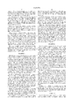
- FIG. 1(a) shows an active matrix display device in which three thin-film transistors (TFTs) are connected with one electrode of one pixel cell 105. All of these TFTs are of the N-channel type.
- the TFTs can also be of the P-channel type. Where each TFT uses a crystalline silicon semiconductor formed by a low-temperature process, the P-channel type produces smaller OFF current and is deteriorated less easily than the N-channel type.
- Two TFTs 101 and 102 share gate interconnects and are connected with a gate signal line.
- the source of the TFT 101 is connected with an image signal line.
- a further TFT 103 which is maintained in conduction is connected between the two TFTs 101 and 102. In order to maintain the TFT 103 in conduction, it is desired to apply a sufficiently high positive potential to the gate so that the TFT 103 is hardly affected by image signal or other signal.
- the gate of the TFT is maintained above +15 V, preferably above +20 V.
- the potential at the gate of the TFT 103 is +11 V
- the potential difference between the gate and source varies around the threshold voltage, i.e., from +1 V to +11 V.
- the capacitance obtained by the TFT 103 varies greatly.
- the potential at the gate of the TFT 103 is +20 V
- the potential difference between the gate and the source varies from +10 V to +30 V but sufficiently remote from the threshold voltage. Therefore, the capacitance obtained by the TFT 103 hardly varies.
- the liquid crystal cell 105 and an auxiliary capacitor 104 are connected with the drain of the TFT 102.
- the other electrode of the liquid crystal cell 105 and the other electrode of the auxiliary capacitor 104 are grounded. If the capacitance of the liquid crystal cell 105 is sufficiently large, the auxiliary capacitor 104 can be dispensed with.
- the ratio of the capacitance of the MOS capacitor 103 to the sum of the capacitance of the auxiliary capacitor 104 and the capacitance of the liquid crystal cell 105 is determined optimally.
- a high-level voltage is applied to the gates of two TFTs 101 and 102, thus turning them ON.
- An electrical current corresponding to an image signal flows through the source of the TFT 101.
- the TFT 103 which is maintained in conduction and connected with the drain of the TFT 101 acts as a capacitor and starts charging. Since the TFT 103 is held in conduction, an electrical current flows from the source of the TFT 102 to the drain, thus electrically charging the auxiliary capacitor 104 and the liquid crystal cell 105.
- a high-level voltage is first applied to the gate electrodes of the two TFTs 101 and 102, thus turning them ON.
- An electrical current flows through the sources of the TFTs, so that the auxiliary capacitor 104 and the liquid crystal cell 105 are electrically charged.
- the present example demonstrates the usefulness of the present invention. Obviously, if a TFT similar to the TFTs 102 and 103 is inserted between TFTs 192 and 104, greater advantages can be obtained, in the same way as in the configuration shown in FIG. 2(D).
- FIG. 1(b) shows an example of pixel of an active matrix circuit in which two TFTs are connected with one pixel electrode. All of the TFTs are of the N-channel type. Similar advantages can be obtained if they are of the P-channel type
- Two TFTs 111 and 112 share gate interconnects and are connected with a gate signal line.
- a MOS capacitor 113 is connected between the source and drain of each TFT.
- the MOS capacitor 113 may be formed by shorting the source of an ordinary TFT to the drain. Since the MOS capacitor uses an N-channel TFT, if the gate is maintained at an appropriate positive potential, the MOS capacitor acts as a capacitor. In order that the MOS capacitor function stably, the potential is preferably maintained at a sufficiently high potential, in the same way as the gate of the TFT 103 of Example 1.
- the gate of the MOS capacitor 113 be maintained at the aforementioned potential for a major portion of the time during which the pixel of interest is not selected.
- the gate of the MOS capacitor 103 is preferably maintained at the potential described above.
- the capacitor 114 and the gate electrode of the MOS capacitor 113 are connected with a capacitor line extending parallel to the gate signal line, and are maintained at the potential for the above-described purpose.
- the liquid crystal cell 115 and the auxiliary capacitor 114 are connected with the drain of the TFT 112.
- the source of the TFT 111 is connected with the image signal line. If the capacitance of the liquid crystal cell 115 is sufficiently large, the auxiliary capacitor 114 is unnecessary.
- an electrical current flows through the source of the TFT 111.
- the MOS capacitor 113 connected with the drain of the TFT 111 is started to be electrically charged.
- An electrical current flows from the source electrode of the TFT 112 to the drain current, thus electrically charging the auxiliary capacitor 114 and the liquid crystal cell 115.
- a low-level voltage is applied to the gate electrodes of the TFTs 111 and 112, so that these TFTs are turned off.
- the voltage at the source electrode of the TFT 111 drops.
- the OFF current from the TFT starts to electrically charge the MOS capacitor 113.
- the MOS capacitor 113 delays the drop of the voltage developed between the drain and source of the TFT connected with the pixel.
- the amount of electric charge released from the auxiliary capacitor and from the liquid crystal cell 115 is reduced.
- the amount of electric charge released from the liquid crystal cell 115 is suppressed until the TFT is driven into conduction during the next frame of image.
- the waveforms of the signals produced during this operation are the same as the waveform produced in Example 1.
- FIG. 1(c) shows an example of pixel of an active matrix circuit in which two TFTs are connected with one pixel electrode. All of the TFTs are of the N-channel type. Similar advantages can be obtained if they are of the P-channel type.
- Two TFTs 121 and 122 share gate interconnects and are connected with a gate signal line.
- a capacitor 123 is connected between the source and drain of each TFT.
- the auxiliary capacitor 124 is formed, using a MOS capacitor.
- the auxiliary capacitor 124 is formed by shorting the source of an ordinary TFT to the drain, in the same way as in the case of the MOS capacitor 113 of Example 2. Since this MOS capacitor is composed of an N-channel TFT, if the gate is maintained at an appropriate positive potential, then the N-channel TFT acts as a capacitor. In order that the N-channel TFT act as a capacitor stably, the gate is preferably maintained at a sufficiently high positive potential, in the same way as in the gate of the MOS capacitor 113 of Example 2.
- the gate of the MOS capacitor 124 be maintained at the aforementioned potential at least for a major portion of the time during which the pixel of interest is not selected.
- the gate of the auxiliary capacitor 124 is preferably maintained at the potential described above.
- the capacitor 123 and the gate electrode of the MOS capacitor 124 are connected with a capacitor line extending parallel to the gate signal line, and are maintained at the potential for the above-described purpose.
- the liquid crystal cell 125 and the auxiliary capacitor 124 are connected with the drain of the TFT 122.
- the source of the TFT 121 is connected with the image signal line.
- the circuit devices constructed in this way operate in the same way as in Examples 1 and 2.
- FIG. 1(d) shows an example of pixel of an active matrix circuit in which two TFTs are connected with one pixel electrode. All of the TFTs are of the N-channel type. Similar advantages can be obtained if they are of the P-channel type.
- Two TFTs 131 and 132 share gate interconnects and are connected with a gate signal line.
- a capacitor 133 is connected between the source and drain of each TFT. This auxiliary capacitor 133 is formed by shorting the source of an ordinary TFT to the drain, in the same way as in the case of the MOS capacitor 113 of Example 2.
- the auxiliary capacitor 134 is formed, also using a MOS capacitor. Since these MOS capacitors are N-channel TFTs, if the gates are maintained at an appropriate positive potential, then the N-channel TFTs act as capacitors. In order that the N-channel TFTs act as capacitors stably, the gates are preferably maintained at a sufficiently high positive potential, in the same way as in the gate of the MOS capacitor 113 of Example 2. In order to implement the present invention, it is necessary that the gates of these MOS capacitors be maintained at the aforementioned potential at least for a major portion of the time during which the pixel of interest is not selected.
- the gates of the auxiliary capacitors are preferably maintained at the potential described above.
- the gate electrodes of the MOS capacitors 133 and 134 are connected with a capacitor line extending parallel to the gate signal line, and are maintained at the potential used for the above-described purpose.
- the liquid crystal cell 135 and the auxiliary capacitor 134 are connected with the drain of the TFT 132.
- the source of the TFT 131 is connected with the image signal line.
- the circuit devices constructed in this way operate in the same way as in Examples 1-3.
- FIG. 1(e) shows an example of pixel of an active matrix circuit in which two TFTs are connected with one pixel electrode. All of the TFTs are of the N-channel type. If they are of the P-channel type, similar advantages can be had.
- Two TFTs 141 and 142 share gate interconnects and are connected with a gate signal line.
- a capacitor 143 is connected between the source and drain of each TFT.
- a resistor 146 is directly inserted between the TFTs 141 and 142. This resistor 146 may be formed by forming a lightly doped region in a semiconductor film constituting the TFTs 141 and 142.
- the auxiliary capacitor 144 is formed, using a MOS capacitor, in the same way as in Example 3. Since the MOS capacitor consists of an N-channel TFT in the same way as in Example 3, if the gate is maintained at an appropriate positive potential, then the N-channel TFT acts as a capacitor. In order that the N-channel TFT act as a capacitor stably, the potential is preferably maintained at a sufficiently high positive potential, in the same way as the gate of the MOS capacitor 123 of Example 3. In order to implement the present invention, it is necessary that the gate of the MOS capacitor 144 be maintained at the aforementioned potential at least for a major portion of the time during which the pixel of interest is not selected.
- the gate of the auxiliary capacitor 144 is preferably maintained at the potential described above.
- the gate electrodes of the MOS capacitors 143 and 144 are connected with a capacitor line extending parallel to the gate signal line, and are maintained at the potential used for the above-described purpose.
- the liquid crystal cell 145 and the auxiliary capacitor 144 are connected with the drain of the TFT 142.
- the source of the TFT 141 is connected with the image signal line.
- the circuit devices constructed in this way operate in the same way as in Examples 1-4.
- the present example relates to the process sequence for fabricating the circuits of Examples 1-4.
- a gate electrode is anodized to form an offset gate. This reduces the OFF current.
- Techniques for anodizing the gate electrode are disclosed in Japanese Patent Laid-Open No. 267667/1993.
- FIGS. 4(A)-4(D) illustrate the process sequence of the present example.
- silicon oxide was deposited as a buffer film 402 having a thickness of 1000 to 3000 ⁇ , e.g., 3000 ⁇ , on a substrate 401 consisting of Corning 7059 glass.
- the substrate 401 measured 100 mm ⁇ 100 mm.
- TEOS was decomposed and deposited by plasma-assisted CVD. This manufacturing step may also be carried out by sputtering techniques.
- the laminate was allowed to stand in an ambient maintained at 550 to 600° C. for 8 to 24 hours to crystallize the amorphous film.
- a trace amount of nickel may be added to promote the crystallization.
- This fabrication step may be carried out by the use of optical annealing relying on laser irradiation. A combination of thermal annealing and optical annealing can also be utilized.
- the silicon film crystallized in this way was etched to form island regions 403.
- a gate-insulating film 404 was formed on these island regions 403.
- This fabrication step may also be carried out by sputtering techniques.
- This film was etched to form gate electrodes 405, 406, and 407 (FIG. 4(A)).
- an electrical current was passed through the gate electrode within an electrolytic solution to anodize it.
- an anodic oxide film having a thickness of 500 to 2500 ⁇ , e.g., 2000 ⁇ , was formed.
- the used electrolytic solution was obtained by diluting L-tartaric acid with ethylene glycol to a concentration of 5% and adjusting the pH to 7.0 ⁇ 0.2 with ammonia.
- the laminate was immersed in this solution.
- the positive terminal of a regulated current source was connected with the gate electrode on the substrate.
- a platinum electrode was connected with the negative terminal.
- a voltage was applied while maintaining the current at 20 mA.
- the oxidation was continued until the voltage reached 150 V.
- the oxidation was continued while maintaining the voltage at 150 V until the current dropped below 0.1 mA.
- an aluminum oxide film, 408, 409, and 410, having a thickness of 2000 ⁇ was obtained.
- an impurity phosphorus, in this example
- Phosphine (PH 3 ) was used as a dopant gas.
- the dose was 1 ⁇ 10 14 to 5 ⁇ 10 15 atoms/cm 2 .
- the accelerating voltage was 60 to 90 kV.
- the dose was 1 ⁇ 10 15 atoms/cm 2 .
- the accelerating voltage was 80 kV.
- N-type doped regions 411-414 were formed (FIG. 4(B)).
- the laminate was irradiated with KrF excimer laser light having a wavelength of 248 nm and a pulse width of 20 nsec to activate the doped regions 411-414.
- the energy density of the laser light was 200 to 400 mJ/cm 2 , preferably 250 to 300 mJ/cm 2 .
- This fabrication step may make use of thermal annealing. Where a catalytic element such as nickel is contained, the doped regions can be activated by thermal annealing at a lower temperature than in normal process, as described in Japanese Patent Laid-Open No. 267989/1994.
- the N-type doped regions were formed in this way.
- the doped regions were remoter from the gate electrode by a distance equal to the thickness of the anodic oxide. That is, an offset gate was formed.
- silicon oxide was formed as an interlayer insulator 415 having a thickness of 5000 ⁇ by plasma-assisted CVD.
- TEOS and oxygen were used as gaseous raw materials.
- the interlayer insulator 415 and the gate-insulating film 404 were etched. Contact holes were formed in the N-type doped region 411.
- an aluminum film was formed by sputtering techniques. The aluminum film was etched to form source electrodes and interconnects, 416. These are extensions to image signal lines (FIG. 4(C)).
- a passivation film 417 was formed.
- a silicon nitride film was grown as the passivation film to a thickness of 2000 to 8000 ⁇ , e.g., 4000 ⁇ , by plasma-assisted CVD, using a mixture gas of NH 3 , SiH 4 , and H 2 .
- the passivation film 417, the interlayer insulator film 415, and the gate-insulating film 404 were etched to form holes over the anodic oxide film 409. Contact holes for connection with pixel electrodes were formed in the N-type doped region 414.
- ITO indium tin oxide
- the pixel electrode 418 was located on the opposite side of the anodic oxide film 409 from the gate electrode 406. Thus, a capacitor 419 was created. If the N-type doped regions 412 and 413 are maintained at the same potential, a MOS capacitor is created between the gate electrode 406 and the underlying silicon semiconductor, the MOS capacitor using the gate-insulating film 404 as a dielectric (FIG. 4(D)).
- An active matrix circuit devices having the N-channel TFTs 421, 422, capacitors 419, 420 were formed.
- the pixel electrodes cooperate with the gates of the MOS capacitors to form capacitors and so the circuit is the same as the circuits shown in FIGS. 1(a) and 1(b).
- FIGS. 4(A)-4(F) are cross-sectional views.
- FIGS. 3(A)-3(D) are top views of the structures shown in these cross sections.
- a TFT is formed by the gate 406.
- the gate 406 does not cross the island region 403 as shown in FIGS. 3(B)-3(D)
- a MOS capacitor is formed.
- a channel can be induced in the substantially intrinsic semiconductor region located under the gate electrode, by placing the gate electrode 406 at an adequate potential. As a result, a capacitor is created.
- the resistive component of the channel is inserted in series with two TFTs which are located on opposite sides of the channel.
- an impurity is introduced first at a high concentration (step illustrated in FIG. 4(B)) and then at a low concentration. If a lightly doped region 480 is formed only close to the gate electrode 406, especially desirable results are obtained. The lightly doped region has a higher sheet resistance than the other doped regions 411-414. Therefore, the circuit shown in FIG. 7(B) is obtained from the circuit (FIG. 7(A)) corresponding to the configuration in which another TFT is inserted in series between two TFTs as shown in FIG. 3(A) (FIGS. 7(A) and 7(B)).
- FIG. 7(D) In the case of the circuit which corresponds to the configuration shown in FIG. 3(B) and in which a MOS capacitor is connected between two TFTs, the circuit shown in FIG. 7(D) is similarly derived (FIGS. 7(C) and 7(D)).
- the resistor 480 serves to reduce the OFF current.
- the resistor 480 serves to reduce the OFF current.
- the capacitor is built, using multilevel metallization, the area occupied is narrow.
- FIG. 3(A) shows standard TFTs.
- FIG. 3(B) shows standard MOS capacitors. Because the channel widths of TFTs used in active matrix circuit devices are generally small, it is difficult to secure sufficient capacitance unless the width of the gate 406 is made sufficiently large. In this case, the island region 403 is widened only in the portion of the MOS capacitor as shown in FIG. 3(C). Furthermore, the shape of the gate 406 may be modified as shown in FIG. 3(D).
- the island region is changed into substantially U-shaped or horseshoe form, as shown in FIGS. 8(A)-8(C).
- a gate signal line and a capacitor line are made to overlap the U-shaped island region. That is, the semiconductor film overlaps the gate signal line, or gate electrodes 405 and 407, at two locations. The semiconductor film overlaps the capacitor line, or the gate electrode 406, at one location.
- the gate signal line is formed so as to extend parallel to the capacitor line. In this case, the gates 405 and 407 can be formed in line. This is advantageous to the layout.
- the gate electrode 406 divides the semiconductor region and so the circuit is similar to the circuit shown in FIG. 3(A).
- the structure shown in FIG. 8(A) is characterized in that the semiconductor region has a region 411 in contact with an image signal line, a region 414 in contact with a pixel electrode, and two N- or P-type regions 412 and 413. These two regions 412 and 413 are separated by a capacitor line and a gate signal line.
- the capacitor line does not completely overlap the semiconductor film but an uncapped semiconductor region 481 is formed as shown in FIG. 8(B), then no problems take place.
- the requirement is that the regions 412 and 413 are separated by the gate signal line (i.e., gate electrodes 405 and 407) and the capacitor line (i.e., the gate electrode 406).
- FIG. 8(C) the semiconductor regions 412 and 413 are not divided by the gate electrode 406 and, therefore, the circuit is similar to the circuit shown in FIG. 3(B).
- the device density can be enhanced mainly by devising the shape of the semiconductor film, or the active layer. If a switching device is built, using five TFTs as shown in FIG. 2(D), then the semiconductor film is shaped like the letter N or S. Row-selecting signal lines and gate signal lines are made to overlap this semiconductor film.
- FIG. 4(E) The present example is shown in FIG. 4(E) in cross section.
- a gate 454 is formed between N-channel TFTs 452 and 453.
- a MOS capacitor 450 is formed between the gate 454 and the underlying silicon semiconductor.
- the capacitor 450 uses a gate-insulating film as a dielectric.
- Another gate 455 is formed between the TFT 453 and the contact of a pixel electrode 457 to create a MOS capacitor 451 similarly.
- a metal interconnect 456 is an extension to an image signal line.
- the first MOS capacitor 450 is formed between the TFTs 452 and 453.
- the second MOS capacitor 451 is formed between the pixel electrode 457 and the TFT 453. Therefore, the present example corresponds to the configuration shown in FIG. 1(d). In the present example, as many as four gates are present but only two contacts are necessary. Consequently, the area occupied can be made relatively small.
- a metal interconnect 474 extends from the interface between N-channel TFTs 472 and 473.
- a gate 477 is formed between the TFT 473 and a pixel electrode 476.
- the metal interconnect 474 extends to the top surface of the gate 477.
- a capacitor 470 is formed, using an anodic oxide as a dielectric.
- Another MOS capacitor 471 is formed, using a gate-insulating film as a dielectric, the gate-insulating film being located between the gate 477 and an underlying silicon semiconductor layer.
- a metal interconnect 475 is an extension to the image signal line.
- a capacitor is created between the gate 471 of the MOS capacitor and the conductive interconnects 474 extending from the TFTs 472 and 473. Since the MOS capacitor is parallel to the pixel electrode 476, the configuration corresponds to the configuration shown in FIG. 1(c).
- FIGS. 5(A)-5(E) The process sequence of the present example is illustrated in FIGS. 5(A)-5(E).
- silicon oxide was deposited as a buffer layer 502 to a thickness of 2000 ⁇ on a substrate 501.
- An island region 503 was formed out of a crystalline silicon film.
- a gate-insulating film 504 was formed on the island region 503.
- an aluminum film having a thickness of 5000 ⁇ was formed by sputtering techniques.
- a thin anodic oxide film having a thickness of 100 to 400 ⁇ was formed on the surface of the aluminum film.
- a photoresist film having a thickness of about 1 ⁇ m was formed by spin coating.
- Gate electrodes 505, 506, and 507 were etched by a well-known photolithographical method.
- Masks of the photoresist 508, 509, and 510 were left on the gate electrode (FIG. 5(A)).
- the laminate was immersed in an aqueous solution of 10% oxalic acid.
- the positive terminal of a regulated current source was connected to the gate electrodes 505 and 507 on the laminate.
- a platinum electrode was connected to the negative terminal.
- an anodization process was carried out. This technique is disclosed in Japanese Patent Laid-Open 338612/1994.
- the anodization was effected at a constant voltage of 5 to 50 V, e.g., 8 V, for 10 to 500 minutes, e.g., 200 minutes.
- a porous anodic oxide, 511 and 512 having a thickness of 5000 ⁇ , was formed on the side surfaces of the gate electrodes 505 and 507.
- the obtained anodic oxide was. porous. Since a masking material, 508 and 510, existed on the top surfaces of the gate electrodes, anodization process hardly progressed. No anodic oxidation was formed on the gate electrode 506 because no current was passed through this electrode 506 (FIG. 5(B)).
- an impurity (boron, in this example) was implanted into the island silicon region 503 by self-alignment techniques, using the gate electrode portion as a mask, to form a P-type doped region.
- diborane B 2 H 6
- the dose was 1 ⁇ 10 14 to 5 ⁇ 10 15 atoms/cm 2 .
- the accelerating voltage was 40 to 90 kV.
- the dose was 1 ⁇ 10 15 atoms/cm 2 , and the accelerating voltage was 65 kV.
- P-type doped regions 516-519 were formed (FIG. 5(C)).
- the laminate was irradiated with KrF excimer laser light having a wavelength of 248 nm and a pulse width of 20 nsec to activate the doped regions 516-519.
- silicon oxide was deposited as an interlayer insulator film 520 having a thickness of 3000 ⁇ by plasma-assisted CVD.
- the interlayer insulator film 520 and the gate-insulating film 504 were etched. Contact holes were created in the P-type doped region 516.
- an aluminum film was formed by sputtering techniques. The aluminum film was etched to form an image signal line 521 (FIG. 5(D)).
- a passivation film 522 was formed.
- the passivation film 522, the interlayer insulator film 520, and the gate-insulating film 504 were etched to form holes over the anodic oxide film 514 and to form contact holes in the P-type doped region 519, the contact holes being used for contact with pixel electrodes.
- ITO was deposited as a film. This ITO film was etched to form a pixel electrode 523. This pixel electrode 523 was opposite to the gate electrode 506.
- a capacitor using the anodic oxide film 514 as a dielectric was created. If the P-type doped regions 517 and 518 are maintained at the same potential, a MOS capacitor is created between the gate electrode 506 and the underlying silicon semiconductor layer. This MOS capacitor uses the gate-insulating film 504 as a dielectric (FIG. 5(E)).
- Active matrix circuit devices comprising the P-channel TFTs 526, 527, the capacitor 524, and the MOS capacitor 525 were formed by the manufacturing steps described thus far.
- each pixel electrode forms a capacitor together with the gate of a MOS capacitor. Therefore, the circuit is similar to the circuits shown in FIGS. 1(a) and 1(b) except that the transistor conductivity type is reversed.
- the OFF currents of the TFTs 526 and 527 are required to be suppressed.
- These TFTs have larger offset widths than the TFTs of Example 6.
- the MOS capacitor needs no offset structure and so the offset width of the MOS capacitor is set to a small value.
- FIGS. 9(A)-9(F) show the manner in which circuits are built according to the present invention.
- Well-known process techniques or the process techniques described in Example 6 or 9 may be used for this purpose and so these techniques will not be described in detail below.
- substantially U-shaped or horseshoe semiconductor regions or active layers 601-604 were formed. Where the active layer 601 is used as a reference layer, the active layer 602 forms the same column and the next row. The active layer 603 forms the next column and the same row. The active layer 604 forms the next column and the next row (FIG. 9(A)).
- Gate signal lines 605, 606 and capacitor lines 607, 608 were formed out of the gate-insulating film.
- the positional relations among the gate signal lines, the capacitor lines, and the active layers were the same as the positional relations shown in FIG. 8 (FIG. 9(B)).
- contact holes (such as 611) were formed at the left ends of the active layers. Then, image signal lines 609 and 610 were created (FIG. 9(C)).
- pixel electrodes 612 and 613 were created in regions surrounded by the gate signal lines and the image signal lines.
- a TFT 614 was formed by the capacitor line 607 and the active layer 601.
- the capacitor line 607 did not overlap the pixel electrode 613 of the same row but overlapped the pixel electrode 612 of the immediately preceding row. That is, with respect to the pixel electrode 613, the capacitor line 608 of the immediately following row overlapped the pixel electrode 613, thus forming a capacitor 615.
- a constant voltage sufficient to operate the TFT 614 as another MOS capacitor was applied to the capacitor lines 607 and 608 in the same way as in the other examples (FIG. 9(D)).
- the capacitor 615 corresponds to the capacitor 104 shown in FIG. 1(A).
- a capacitor can be added without substantially lowering the aperture ratio. This is effective in enhancing the device density.
- FIG. 9(F) shows prior art unit pixel (see FIG. 2(A)) formed in a region surrounded by row-selecting signal lines and image signal lines which are regularly spaced from each other.
- the region shielded by the auxiliary capacitor 202 is the same as the region of the present example (FIG. 9(D)).
- the semiconductor region 601 is almost totally covered with the signal lines 605 and 607. Consequently, the aperture ratio does not decrease.
- gate electrodes branching from the row-selecting signal lines deteriorate the aperture ratio.
- the capacitor line 607 is located on the opposite side of the gate signal line 605.
- the adjacent pixel electrode 612 overlaps the capacitor line 607 of the same row but does not overlap the image signal line 609 or 610.
- the pixel electrodes should not overlap any region to which an image signal is applied. This requirement is satisfied because of the features described above. Furthermore, the aperture ratio can be enhanced.
- FIGS. 10(A)-10(F) illustrate the process sequence of the present example.
- silicon oxide was deposited as a buffer layer 702 to a thickness of 2000 ⁇ on a substrate 701.
- Island regions 703 were formed out of a crystalline silicon film.
- a gate-insulating film 704 was formed on the island regions.
- gate electrodes 705-707 consisting mainly of aluminum and coated with a barrier type anodic oxide were formed by the use of techniques similar to the techniques used in Example 9.
- a porous anodic oxide 708 was deposited on the side surfaces of only the central gate electrode (FIG. 10(A)).
- the gate-insulating film 704 was etched by dry etching. As a result, the gate-insulating film was left on those portions 709-711 which were located under the gate electrodes 705-707 and under their respective anodic oxide portions (FIG. 10(B)).
- porous anodic oxide 708 was selectively removed. Techniques for this manufacturing step are disclosed in the above-cited Japanese Patent Laid-Open No. 338612/1994 (FIG. 10(C)).
- an impurity (phosphorus, in this example) was implanted into the island silicon regions 703 by self-alignment techniques, using the gate electrode portion and the gate-insulating film 710 as a mask, to form an N-type doped region.
- this ion implantation process consisted substantially of two steps. In the first step, the impurity was implanted at a high accelerating voltage and at a low dose. In the second step, the impurity was implanted at a low accelerating voltage and at a high dose. In an example of the first step, the accelerating voltage was 80 kV, and the dose was 1 ⁇ 10 13 atoms/cm 2 . In an example of the second step, the accelerating voltage was 20 kV, and the dose was 5 ⁇ 10 14 atoms/cm 2 .
- the first step a high accelerating energy can be imparted to ions. Therefore, ions can be implanted through the gate-insulating film 710.
- the doped regions formed at this time are lightly doped.
- heavily doped regions can be formed but it is impossible to introduce ions through the gate-insulating film 710. As a result, heavily doped N-type regions 712-715 and lightly-doped N-type regions 716, 717 could be separately formed (FIG. 10(D)).
- a silicon oxide film 718 was formed as an interlayer insulator film to a thickness of 3000 ⁇ by plasma-assisted CVD.
- the interlayer insulator film 718 was etched, and contact holes were formed in the heavily doped N-type regions 712.
- an aluminum film was formed by sputtering techniques. The aluminum film was etched to form image signal lines 719.
- a passivation film 720 was formed.
- the passivation film 720 and the interlayer insulator film 718 were etched to form contact holes in the heavily doped N-type region 715, the contact holes being used for connection with pixel electrodes.
- An ITO film was formed and etched to form pixel electrodes 721 (FIG. 10(E)).
- a circuit as shown in FIG. 10(F) could be obtained by the fabrication steps described thus far. This can be used as a capacitor by maintaining the gate electrode 706 at an appropriate potential.
- the lightly doped N-type regions 716 and 717 act as resistors inserted in series with TFTs and are effective in reducing the OFF current (FIG. 10(E)).
- FIGS. 11(A)-11(C) show the manner in which circuits are built according to the present invention.
- Well-known process techniques or the process techniques-described in Example 6 or 9 may be used for this purpose and so these techniques will not be described in detail below.
- the concept of the circuit arrangement of the present example is essentially the same as the concept of Example 10 (FIGS. 9(A)-9(F)).
- TFTs are protected against extraneous light by making positive use of shielding of capacitor lines and image signal lines which are formed out of a shielding film.
- a black matrix circuit is built from the TFTs to clearly distinguish colors among pixels.
- the process sequence is the same as the sequence used in Example 10. First, a substantially U-shaped active layer 801 was formed. Then, a gate-insulating film (not shown) was deposited on the active layer. Gate signal lines 802 and capacitor lines 803 were formed. The capacitor lines were arranged so as to surround the portion where pixel electrodes were formed as shown in FIG. 11(A).
- contact holes were formed at the left end of the active layer. Also, an image signal line 804 was formed. This image signal line was also so arranged as to cover the surroundings of the pixel electrodes (especially, the surroundings of TFTs) (FIG. 11(B)).
- the transparent portions are only the central portion in which the pixel electrodes are formed and two dot-like portions located at the top right end of each pixel.
- the gaps between the gate signal lines and the capacitor lines are not filled up with the image signal lines.
- the other portions are shielded against light by the gate signal lines, the capacitor lines, and the image signal lines.
- the image signal lines are arranged on the TFTs. These image signal lines prevent extraneous light from entering the TFTs. This is effective in stabilizing the characteristics of the TFTs.
- a pixel electrode 805 was formed in the above-described central portion.
- the transparent regions excluding the pixel electrode were only the gap 807 between the pixel electrode 805 and the image signal line 804 and the gap 806 among the gate signal line 802, the capacitor line 803, and the image signal line 804.
- the gap 807 was necessary to prevent the image signal line from overlapping the pixel electrode.
- the gap 806 was needed to separate the adjacent image signal lines. However, these gaps 807 and 806 have sufficiently small areas.
- a structure equivalent to a black matrix could be obtained, using existing conductive interconnects without forming a black matrix (FIG. 11(C)).
- TFT portions of the present example is conceptually shown in FIG. 12. As shown, a TFT located on the side of an image signal line 804 is totally coated with the image signal line 804. A TFT located in the center is partially coated with the image signal line 804.
- capacitor lines often overlap pixel electrodes and image signal lines. Therefore, sufficient care must be exercised in providing insulation between metallization layers. The insulation can be effectively enhanced by forming an anodic oxide film at least on the top surfaces of capacitor lines (FIG. 12).
- FIGS. 13 and 14 An appropriate insulating film may or may not be formed as a buffer layer on a dielectric surface 1 of a substrate.
- an island-shaped thin-film silicon region 2 having a thickness of 100 to 1500 ⁇ , e.g., 800 ⁇ , was formed either on the substrate or on the dielectric surface 1.
- the silicon region 2 had pads 3, 5 for formation of contacts and an intervening channel formation portion 4.
- the silicon region can be made of either amorphous silicon or polycrystalline silicon (FIG. 13).
- a gate-insulating film 6 was formed out of silicon oxide to a thickness of 1200 ⁇ .
- An appropriate amount of phosphorus was added to the polysilicon film to improve its conductivity.
- This polysilicon film was formed to a thickness of 3000 ⁇ by LPCVD.
- This polysilicon film was etched to form a gate line 7.
- the material of the gate line is not limited to polysilicon.
- metal materials such as aluminum and tantalum can also be employed. Especially, where aluminum is used, the sheet resistance of the gate line can be effectively lowered (FIG. 14).
- an impurity phosphorus, in this example
- an impurity phosphorus, in this example
- doped regions 8 (source) and 9 (drain) were created.
- no doped region was formed under the gate electrode. Rather, a channel 4 was created.
- the introduced dopant might be activated by appropriate means such as thermal annealing or laser annealing (FIG. 15).
- an aluminum film having a thickness of 5000 ⁇ was formed by sputtering techniques.
- the aluminum film was etched to form a source line 12.
- the source line 12 formed a contact with a source 8 (FIG. 17).
- silicon nitride or silicon oxide was deposited as a second interlayer insulator layer 13 to a thickness of 2000 to 5000 ⁇ , e.g., 000 ⁇ .
- a contact hole extending to a pad 5 was formed in the second interlayer insulator layer 13, the pad 5 being used for contact with an island silicon region.
- An ITO film having a thickness of 1000 ⁇ was formed by sputtering techniques. The ITO film was etched to form a pixel electrode 14 (FIG. 18).
- the direction of channel in the TFT (directed from the source to the drain) is parallel to the source line as shown in FIG. 19. This is a feature compared with the prior art TFT shown in FIG. 22.
- the channel 4 is located under the source line 12.
- the source and drain adjacent to the channel 4 overlap with the source line, thus forming a parasitic capacitor, unlike the prior art TFT.
- a parasitic capacitor 15 formed between the drain 9 and the source line 12 presents a problem during operation of the active matrix circuit.
- the drain 9 and the source line 12 are isolated from each other by the first interlayer insulator 10.
- the width of the island silicon region where an overlap is formed can be made sufficiently small. This overlap is sufficiently smaller than the area of the pixel electrode 14. For these and other reasons, the image displayed is not greatly affected.
- each island silicon region was shaped into a substantially U-shaped form. Gate lines were formed so as to intersect the silicon region. Consequently, two channels, or TFTs, 16 and 17 were formed. One end of the island silicon region was brought into contact with a source line. The source line was formed over the channel 16. The other end was brought into contact with a pixel electrode.
- two TFTs connected in series are formed for each one pixel, as shown in FIG. 20. It is known that in this structure, leakage current from the pixel can be reduced, as disclosed in Japanese Patent Publication No. 38755/1991. In the present example, it is not necessary to form branch lines extending from gate lines, unlike the prior art techniques. Therefore, the area occupied by TFTs can be reduced. Furthermore, the aperture ratio can be enhanced.
- the drain of the left TFT acting also as the source of the right TFT overlaps the source line, thus forming a parasitic capacitor 18.
- one TFT is added between the parasitic capacitor 18 and the pixel electrode, compared with Example 1. Consequently, the effect is limited (FIG. 20).
- the drop of voltage developed across a liquid crystal cell can be successfully suppressed by connecting plural TFTs and/or an appropriate capacitor.
- the voltage developed between the source and drain is maintained at a low level throughout the driving process.
- deteriorations of TFTs depend on the voltage developed between the source and drain. The deteriorations can be prevented by making use of the present invention.
- the present invention can be advantageously used in applications where images are required to be displayed at higher quality. That is, where quite large number of color tones of more than 256 gray levels are represented, it is necessary that electric discharge in the liquid crystal cell be suppressed within 1% during one frame. None of the conventional systems illustrated in FIGS. 2(A) and 2(B), respectively, are suitable for this purpose.
- the present invention is especially adapted for an active matrix display using TFTs comprising a crystalline silicon semiconductor, the active matrix display being suitable for active matrix addressing, especially where the number of rows of picture elements is large.
- the active matrix display being suitable for active matrix addressing, especially where the number of rows of picture elements is large.
- each row is activated for a short time. Therefore, TFTs of crystalline silicon semiconductor are not suitable for this matrix display.
- TFTs using crystalline silicon semiconductor suffer from large OFF current. For this reason, the present invention can contribute to this technical field because the invention can suppress the OFF current.
- TFTs comprising amorphous silicon semiconductor are employed to advantage.
- TFTs and MOS capacitors are mainly of the top gate type.
- the invention can be applied with similar utility to the bottom gate type and other structures.
- a switching device comprising a combination of the top gate type and the bottom gate type may be used.
- the present invention can enhance the aperture ratio of an active matrix circuit. In consequence, the display characteristics of an electrooptical device using this active matrix circuit can be improved. In this way, the present invention is industrially advantageous.
Abstract
A liquid crystal display device including (a) a plurality of source lines over a substrate; (b) a plurality of gate lines over the substrate in an orthogonal relation to the plurality of the source lines; and (c) a plurality of pixels in a matrix array at intersections of the source lines and gate lines, wherein, (i) each of the pixels is formed over the substrate and includes, at least a thin film transistor having a channel region, source and drain regions, a gate insulator adjacent to the channel region, and a gate electrode adjacent to the gate insulating film; (ii) a pixel electrode connected to the thin film transistor, (iii) a storage capacitor operationally connected to the thin film transistor, the storage capacitor including an insulating film and at least first and second electrodes with the insulating film interposed therebetween, and (iv) wherein the first electrode may comprise the same semiconductor material as the channel region, and/or at least the channel region of the in film transistor may be covered by an associated one of the source lines.
Description
This is a Divisional application of Ser. No. 08/456,404, filed Jun. 1, 1995 now U.S. Pat. No. 5,650,636.
1. Field of the Invention
The present invention relates to an active matrix display construction and, more particularly, to a circuit and device structure for improving the quality of the image displayed on the viewing screen.
2. Description of the Related Art
FIG. 2(A) schematically shows a conventional active matrix display. In this figure, the region 204 surrounded by the broken line is a display region. Thin-film transistors 201 (only one is shown) are arranged in rows and columns in this region 204. Conductive interconnects connected with the source electrodes of the thin-film transistors 201 are image signal lines or data signal lines 206. Conductive interconnects connected with the gate electrodes of the thin-film transistors 201 are gate-selecting signal lines 205 (only one is shown).
We now take notice of driver devices. The thin-film transistors 201 act to switch data, and drive a liquid-crystal cell 203. Auxiliary capacitors 202 (only one is shown) are used to reinforce the capacitance of the liquid-crystal cell, and act to hold image data. The thin-film transistors 201 are employed to switch image data indicated by the voltage applied across the liquid-crystal material. Let VGS be the gate voltage of each thin-film transistor. Let ID be the drain current. The relation VGS -ID is shown in FIG. 3. In particular, if the gate voltage VGS is in the cutoff region of the thin-film transistor, the drain current ID is increased, and it is called OFF current.
In the case of an N-channel thin-film transistor, the OFF current flowing when the gate voltage VGS is biased negatively is stipulated by the current flowing through a PN junction formed between a P-type layer and an N-type layer The P-type layer is induced in the surface of the thin-film semiconductor. The N-type layer is formed in the source and drain regions. Because numerous traps exist in the thin-film transistor, this PN junction is incomplete and so the junction tends to produce a leakage current. As the gate electrode is biased more negatively, the OFF current is increased, for the following reason. The concentration of carriers in the P-type layer formed in the surface of the thin-film semiconductor is increased, thus reducing the width of the energy barrier in the PN junction. As a result, the electric field is concentrated, so that the current leaking from the junction increases.
The OFF current produced in this way depends greatly on the source/drain voltage. For example, it is known that as the voltage applied between the source and drain of a thin-film transistor is increased, the OFF current is increased drastically. That is, the OFF current produced when a voltage of 10 V is applied is not merely twice as large as the OFF current produced when a voltage of 5 V is applied between the source and drain. Rather, the ratio of the former OFF current to the latter OFF current reaches 10 or even 100. This nonlinearlity also depends on the gate voltage. Generally, where the reverse bias applied to the gate electrode is large (in the case of an N-channel type, a large negative voltage), the ratio is large.
In an attempt to solve this problem, the multi-gate method has been proposed as described in Japanese Patent Publication Nos. 44195/1993 and 44196/1993. In this method, thin-film transistors are connected in series. This method is intended to reduce the OFF current of each individual thin-film transistor, by reducing the voltage applied between the source and drain of each thin-film transistor. For example, where two thin-film transistors are connected in series as shown in FIG. 2(B), the voltage applied between the source and drain of each thin-film transistor is halved. This reduces the OFF current by a factor of 10 or even 100 because of the principle described above.
TFTs, source lines, and gate lines are formed in an active matrix circuit. These elements hinder transmission of light. Specifically, the ratio (aperture ratio) of the area of the region that can be used for image display to the whole area is small. Typically, the aperture ratio is 30 to 60%. Especially, in a backlit display device comprising an active matrix circuit backlit with intense light, if the aperture ratio is small, a major portion of the incident light is absorbed by TFTs and by the liquid-crystal material and so these TFTs and liquid-crystal material get hot. As a result, their characteristics are deteriorated.
However, as the image displayed on a liquid crystal display is required to have stricter characteristics, it is more difficult to reduce the OFF current by a required amount by the aforementioned multi-gate method. In particular, if the number of the gate electrodes (or, the number of thin-film transistors) is increased to 3, 4, and 5, then the voltage applied between the source and drain of each TFT decreases to one-third, one-fourth, and one-fifth, respectively. In this way, the latter voltage does not decrease rapidly. Therefore, in order to reduce the voltage between the source and drain by a factor of 100, as many as 100 gates are needed. That is, in this method, the resulting advantage is most conspicuous where the number of gates is two. However, if more gates are provided, great advantages cannot be expected.
In view of the foregoing problems, the present invention has been made.
It is an object of the invention to provide a pixel circuit which reduces the voltage applied between the source and drain of each TFT (thin-film transistor) connected with a pixel electrode down to a level which is about less than one-tenth, preferably less than one-hundredth, of the level normally obtained, thus reducing the OFF current. This pixel circuit is characterized in that the number of TFTs used for the above-described object is reduced sufficiently. Preferably, the number of the TFTs is less than 5, more preferably 3.
It is another object of the invention to provide an active matrix display comprising TFTs which are prevented from being irradiated with light without lowering the aperture ratio.
The theory underlying the inventive concept is illustrated in FIG. 2(C), where TFTs (thin-film transistors) 221 and 222 are connected in series. A capacitor 223 is inserted between these TFTs 221 and 222 to lower the voltage produced between the source and drain of the TFT 222 especially located on the side of a pixel electrode. This reduces the OFF current of the TFT 222. The illustrated capacitor 224 is not always necessary. Rather, this capacitor 224 increases the burden imposed during writing. Therefore, if the ratio of the capacitance of a pixel cell 225 to the capacitance 223 is appropriate, then it may be desired to dispense with the capacitor 224.
The operation is next described in detail. When a select signal is sent to a gate signal line 226, both TFTs 221 and 222 are turned ON. Depending on the signal on an image signal line 227, the capacitors 223, 224 and the pixel cell 225 are electrically charged. When they are fully charged, i.e., when a balanced state is obtained, the voltage applied to the source of the TFT 222 is substantially equal to the voltage applied to the drain of the TFT 222.
Under this condition, if the select signal is made to cease, both TFTs 221 and 222 are turned OFF. Then, a signal for other pixel is applied to the image signal line 227. The TFT 221 produces a finite amount of leakage current. Consequently, the electric charge stored in the capacitor 223 is released, so that the voltage drops but at a rate roughly equal to the rate at which the voltage developed across the capacitor 202 of the normal active matrix circuit shown in FIG. 2(A) drops.
On the other hand, with respect to the TFT 222, the voltage developed between the source and drain is initially almost zero. For this reason, the OFF current is quite weak. Then, the voltage developed across the capacitor 223 drops. Therefore, the voltage between the source and drain increases gradually. This, in turn, increases the OFF current. Obviously, increases in the OFF current lower the voltage developed across the pixel cell 225 sufficiently more mildly than in the case of the normal active matrix circuit shown in FIG. 2(A).
For example, it is assumed that the TFTs 201 and 221 have similar characteristics and that the voltage developed across the capacitor 202 changes from 10 V to 9 V, or 90%, during one frame. In the case illustrated in FIG. 2(A), the voltage developed across the pixel cell 203 drops down to 9 V during one frame. However, in the case illustrated in FIG. 2(C), even if the voltage developed across the capacitor 223 drops to 9 V, the OFF current is quite small because the voltage between the source and drain of the TFT 222 is 1 V. This holds true when one frame ends. Consequently, the accumulated amount of electric charge released from the pixel cell 225 and from the capacitor 224 is quite small. Hence, the voltage developed across the pixel cell 225 is substantially maintained at 10 V.
It is not easy to compare the case illustrated in FIG. 2(A) with the case illustrated in FIG. 2(B). In FIG. 2(B), the voltage applied between the source and drain of one TFT is half (or 5 V) of the voltage (10 V) applied in the case of FIG. 2(A). It is unlikely that the voltage between the source and drain is 1 V, unlike the case of TFT 222 shown in FIG. 2(C). This is one advantage of the present invention.
If LDD regions or offset regions are inserted in the channels of the TFTs 221 and 222, then these regions form drain resistors and source resistors, respectively. This mitigates the electric field strength at the drain junction. Obviously, this reduces the OFF current further.
If a combination of TFTs and capacitors is added as shown in FIG. 2(D), then greater effect can be produced. However, the rate at which the effect is increased is lower than in the case in which the configuration shown in FIG. 2(A) is replaced by the configuration shown in FIG. 2(C).
In the above-described structure, the capacitors 223 and 224 can be ordinary capacitors. If one or both of them are MOS capacitors, then integration can be accomplished more efficiently. As mentioned previously, the capacitor 224 is not always necessary. If a lightly doped region is formed between the TFTs 221 and 222 to form a circuit configuration in which a resistor is inserted in series, then the OFF current can be reduced further.
Each capacitor consists of a fixed capacitor comprising two opposite metal electrodes. Instead, each capacitor may consist of a MOS capacitor formed by laminating a gate-insulating film and a gate electrode on a substantially intrinsic semiconductor film. The MOS capacitor is characterized in that the capacitance is varied by the potential at the gate electrode.
In one example of the MOS capacitor, three or more TFTs are connected in series with each one pixel electrode. At least one of them excluding those of the series connected TFTs which are located at opposite ends is maintained in conduction and used as a capacitor. In another example, a MOS capacitor is connected to the junction of the drain of one of the TFTs connected in series and the source of the other TFT. A stable electrostatic capacitance is obtained by maintaining the gate electrode of the MOS capacitor at an appropriate potential.
The present invention is characterized in that source lines are formed so as to cover channels in TFTs. The TFTs can be the top gate type obtained by forming a thin-film semiconductor region, gate lines (gate electrodes), an interlayer insulator, and source lines in this order. Alternatively, the TFTs can be the bottom gate type obtained by forming gate lines (gate electrodes), a thin-film semiconductor region, an interlayer insulator, and source lines in this order. It is to be noted that an ordinary active matrix circuit using bottom gate TFTs has no interlayer insulator. In the present invention, however, an interlayer insulator is needed to provide insulation between channel and source lines.
FIGS. 21 and 22 show conventional arrangements of TFTs in active matrix circuits. Gate lines 19 (only one is shown) and source lines 21 (only one is shown) are arranged so as to cross each other substantially at right angles. Branch lines 20 (only one is shown) extend from the gate lines and are made to overlap thin-film semiconductor regions. Thus, the branch lines 20 are used as gate electrodes of TFTs. At one end of each thin-film semiconductor region, a pixel electrode 22 and a contact 25 are formed. At the other end, a source line and a contact 24 are formed.
That portion of each thin-film semiconductor region which substantially overlaps the gate line is a channel 23. As shown in FIGS. 21 and 22, the channel 23 is widely spaced from the source line 21. The branch line 20 from the gate line increases the area occupied by the TFT, thus deteriorating the aperture ratio.
In the present invention, any structure corresponding to the branch line 20 is not formed. A channel is formed under a source line. This reduces the area occupied by the TFT. Also, the aperture ratio can be enhanced. The channel in a TFT is easily affected by light. Therefore, the whole TFT is normally enclosed. Furthermore, a light-shielding film is formed. This further lowers the aperture ratio. In the present invention, a source line is formed so as to cover the channel, thus shielding the channel from extraneous light. Consequently, it is not necessary to form a light-shielding film. This is quite effective in enhancing the aperture ratio.
The active matrix circuit of this construction is quite advantageously used for a backlit display device. As described above, a backlit display device is required to have a high aperture ratio. In addition, the device is illuminated with intense light. Hence, it is imperative that TFTs be shielded from light. In the present invention, light is projected from above source lines. This assures that the source lines shield the channels in the TFTs from light.
Other objects and features of the invention will appear in the course of the description thereof, which follows.
FIGS. 1(a)-1(e) are fragmentary circuit diagrams of active matrix circuit devices according to the invention;
FIG. 2(A) is a fragmentary schematic circuit diagram of the prior art active matrix circuit;
FIGS. 2(B)-2(D) are fragmentary schematic circuit diagrams of active matrix circuits according to the invention;
FIGS. 3(A)-3(D) are diagrams illustrating arrangements of semiconductor regions and gates according to the invention;
FIGS. 4(A)-4(F) are cross-sectional views of active matrix circuit devices according to the invention, illustrating the process sequence of a method of fabricating the circuit devices;
FIGS. 5(A)-15(E) are cross-sectional views of active matrix circuit devices according to the invention, illustrating the process sequence of another method of fabricating the circuit devices;
FIG. 6 is a diagram illustrating the manner in which an active matrix circuit device according to the invention is driven;
FIGS. 7(A)-7(D) are diagrams of arrangements and circuits comprising semiconductor regions and gates according to the invention;
FIGS. 8(A)-8(C) are diagrams showing arrangements of semiconductor regions and gates according to the invention;
FIGS. 9(A)-9(F) are diagrams showing arrangements of pixel electrodes and other components according to the invention;
FIGS. 10(A)-10(E) are cross-sectional views of active matrix circuit devices, illustrating the process sequence of a further method of fabricating the circuit devices according to the invention;
FIG. 10(F) is a circuit diagram of an active matrix circuit according to the invention;
FIGS. 11(A)-11(C) are diagrams showing arrangement of pixel electrodes and other components according to the invention;
FIG. 12 is a cross-sectional view of active matrix circuit devices according to the invention;
FIG. 13 is a top view and a cross-sectional view of a TFT, illustrating a manufacturing step for fabricating the TFT according to the invention;
FIG. 14 is a top view and a cross-sectional view of another TFT, illustrating a manufacturing step for fabricating the TFT according to the invention;
FIG. 15 is a top view and a cross-sectional view of a further TFT, illustrating a manufacturing step for fabricating the TFT according to the invention;
FIG. 16 is a top view and a cross-sectional view of a yet other TFT, illustrating a manufacturing step for fabricating the TFT according to the invention;
FIG. 17 is a top view and a cross-sectional view of a yet further TFT, illustrating a manufacturing step for fabricating the TFT according to the invention;
FIG. 18 is a top view and a cross-sectional view of a still other TFT, illustrating a manufacturing step for fabricating the TFT according to the invention;
FIG. 19 is a top view and a circuit diagram of an additional TFT, illustrating a manufacturing step for fabricating the TFT according to the invention;
FIG. 20 is a top view and a circuit diagram of a still further TFT, illustrating a manufacturing step for fabricating the TFT according to the invention;
FIG. 21 is a circuit diagram showing a conventional arrangement of TFTs; and
FIG. 22 is a circuit diagram illustrating another conventional arrangement of TFTs.
FIG. 1(a) shows an active matrix display device in which three thin-film transistors (TFTs) are connected with one electrode of one pixel cell 105. All of these TFTs are of the N-channel type. The TFTs can also be of the P-channel type. Where each TFT uses a crystalline silicon semiconductor formed by a low-temperature process, the P-channel type produces smaller OFF current and is deteriorated less easily than the N-channel type.
Two TFTs 101 and 102 share gate interconnects and are connected with a gate signal line. The source of the TFT 101 is connected with an image signal line. A further TFT 103 which is maintained in conduction is connected between the two TFTs 101 and 102. In order to maintain the TFT 103 in conduction, it is desired to apply a sufficiently high positive potential to the gate so that the TFT 103 is hardly affected by image signal or other signal.
For example, where the image signal varies from -10 V to +10 V, the gate of the TFT is maintained above +15 V, preferably above +20 V. For instance, if the potential at the gate of the TFT 103 is +11 V, the potential difference between the gate and source varies around the threshold voltage, i.e., from +1 V to +11 V. Also, the capacitance obtained by the TFT 103 varies greatly. On the other hand, if the potential at the gate of the TFT 103 is +20 V, the potential difference between the gate and the source varies from +10 V to +30 V but sufficiently remote from the threshold voltage. Therefore, the capacitance obtained by the TFT 103 hardly varies.
The liquid crystal cell 105 and an auxiliary capacitor 104 are connected with the drain of the TFT 102. The other electrode of the liquid crystal cell 105 and the other electrode of the auxiliary capacitor 104 are grounded. If the capacitance of the liquid crystal cell 105 is sufficiently large, the auxiliary capacitor 104 can be dispensed with. The ratio of the capacitance of the MOS capacitor 103 to the sum of the capacitance of the auxiliary capacitor 104 and the capacitance of the liquid crystal cell 105 is determined optimally.
The operation of the configuration shown in FIG. 1(a) is now described. A high-level voltage is applied to the gates of two TFTs 101 and 102, thus turning them ON. An electrical current corresponding to an image signal flows through the source of the TFT 101. The TFT 103 which is maintained in conduction and connected with the drain of the TFT 101 acts as a capacitor and starts charging. Since the TFT 103 is held in conduction, an electrical current flows from the source of the TFT 102 to the drain, thus electrically charging the auxiliary capacitor 104 and the liquid crystal cell 105.
Then, if a low-level voltage is impressed on the gates of the TFTs 101 and 102, they are biased into cutoff. The voltage developed across the source of the TFT 101 drops, so that an OFF current flows through the TFT 103 which is kept in conduction. Thus, electrical discharging is started. However, the capacitance of the invariably conducting TFT 103 delays the drop of the voltage between the drain and source of the TFT connected to the pixel. Consequently, the amount of electric charge released from the auxiliary capacitor 104 and from the liquid crystal cell 105 decreases. The amount of electric charge released from the liquid crystal cell 105 is suppressed until the TFT is driven into conduction during the next frame of image. The drain voltage varied in this way is indicated by curve (a) in FIG. 6.
Referring again to FIG. 1(a), we now discuss a circuit in which the invariably conducting N-channel TFT 103 has been omitted. The two N-channel TFTs 101 and 102 share the gate interconnects. The liquid crystal cell 105 and the auxiliary capacitor 104 are connected to the drain of the TFT 102. This is the circuit shown in FIG. 2(B) and known as a so-called multi-gate circuit.
A high-level voltage is first applied to the gate electrodes of the two TFTs 101 and 102, thus turning them ON. An electrical current flows through the sources of the TFTs, so that the auxiliary capacitor 104 and the liquid crystal cell 105 are electrically charged.
Then, a low-level voltage is applied to the gates of the TFTs 101 and 102. As a result, the TFTs 101 and 102 are biased into cutoff. The voltage developed across the source of the TFT 101 drops. This lowers the voltage at the drain of the TFT 102. Consequently, the auxiliary capacitor 104 and the liquid crystal cell 105 start to electrically discharge. The drain voltage varied in this way is indicated by curve (b) in FIG. 6. The amount of electric charge released is greater than the amount of electric charge released in the case indicated by curve (a). Also, the voltage drop is greater.
The present example demonstrates the usefulness of the present invention. Obviously, if a TFT similar to the TFTs 102 and 103 is inserted between TFTs 192 and 104, greater advantages can be obtained, in the same way as in the configuration shown in FIG. 2(D).
FIG. 1(b) shows an example of pixel of an active matrix circuit in which two TFTs are connected with one pixel electrode. All of the TFTs are of the N-channel type. Similar advantages can be obtained if they are of the P-channel type
Two TFTs 111 and 112 share gate interconnects and are connected with a gate signal line. A MOS capacitor 113 is connected between the source and drain of each TFT. The MOS capacitor 113 may be formed by shorting the source of an ordinary TFT to the drain. Since the MOS capacitor uses an N-channel TFT, if the gate is maintained at an appropriate positive potential, the MOS capacitor acts as a capacitor. In order that the MOS capacitor function stably, the potential is preferably maintained at a sufficiently high potential, in the same way as the gate of the TFT 103 of Example 1.
In order to implement the present invention, it is necessary that the gate of the MOS capacitor 113 be maintained at the aforementioned potential for a major portion of the time during which the pixel of interest is not selected. When the pixel is selected, i.e., a signal appearing on the image signal line is being written to the pixel, the gate of the MOS capacitor 103 is preferably maintained at the potential described above. The capacitor 114 and the gate electrode of the MOS capacitor 113 are connected with a capacitor line extending parallel to the gate signal line, and are maintained at the potential for the above-described purpose.
The liquid crystal cell 115 and the auxiliary capacitor 114 are connected with the drain of the TFT 112. The source of the TFT 111 is connected with the image signal line. If the capacitance of the liquid crystal cell 115 is sufficiently large, the auxiliary capacitor 114 is unnecessary.
The operation of the configuration shown in FIG. 1(b) is now described. For simplicity, it is assumed that the gate of the MOS capacitor 113 is maintained at a sufficiently high positive potential. First, a high-level voltage is applied to the gates of two TFTs 111 and 112, thus biasing them into conduction.
As a result, an electrical current flows through the source of the TFT 111. The MOS capacitor 113 connected with the drain of the TFT 111 is started to be electrically charged. An electrical current flows from the source electrode of the TFT 112 to the drain current, thus electrically charging the auxiliary capacitor 114 and the liquid crystal cell 115.
Thereafter, a low-level voltage is applied to the gate electrodes of the TFTs 111 and 112, so that these TFTs are turned off. The voltage at the source electrode of the TFT 111 drops. The OFF current from the TFT starts to electrically charge the MOS capacitor 113. However, the MOS capacitor 113 delays the drop of the voltage developed between the drain and source of the TFT connected with the pixel. The amount of electric charge released from the auxiliary capacitor and from the liquid crystal cell 115 is reduced. The amount of electric charge released from the liquid crystal cell 115 is suppressed until the TFT is driven into conduction during the next frame of image. The waveforms of the signals produced during this operation are the same as the waveform produced in Example 1.
FIG. 1(c) shows an example of pixel of an active matrix circuit in which two TFTs are connected with one pixel electrode. All of the TFTs are of the N-channel type. Similar advantages can be obtained if they are of the P-channel type.
Two TFTs 121 and 122 share gate interconnects and are connected with a gate signal line. A capacitor 123 is connected between the source and drain of each TFT.
The auxiliary capacitor 124 is formed, using a MOS capacitor. In particular, the auxiliary capacitor 124 is formed by shorting the source of an ordinary TFT to the drain, in the same way as in the case of the MOS capacitor 113 of Example 2. Since this MOS capacitor is composed of an N-channel TFT, if the gate is maintained at an appropriate positive potential, then the N-channel TFT acts as a capacitor. In order that the N-channel TFT act as a capacitor stably, the gate is preferably maintained at a sufficiently high positive potential, in the same way as in the gate of the MOS capacitor 113 of Example 2.
In order to implement the present invention, it is necessary that the gate of the MOS capacitor 124 be maintained at the aforementioned potential at least for a major portion of the time during which the pixel of interest is not selected. When the pixel is selected, i.e., a signal appearing on the image signal line is being written to the pixel, the gate of the auxiliary capacitor 124 is preferably maintained at the potential described above. The capacitor 123 and the gate electrode of the MOS capacitor 124 are connected with a capacitor line extending parallel to the gate signal line, and are maintained at the potential for the above-described purpose.
The liquid crystal cell 125 and the auxiliary capacitor 124 are connected with the drain of the TFT 122. The source of the TFT 121 is connected with the image signal line. The circuit devices constructed in this way operate in the same way as in Examples 1 and 2.
FIG. 1(d) shows an example of pixel of an active matrix circuit in which two TFTs are connected with one pixel electrode. All of the TFTs are of the N-channel type. Similar advantages can be obtained if they are of the P-channel type.
Two TFTs 131 and 132 share gate interconnects and are connected with a gate signal line. A capacitor 133 is connected between the source and drain of each TFT. This auxiliary capacitor 133 is formed by shorting the source of an ordinary TFT to the drain, in the same way as in the case of the MOS capacitor 113 of Example 2.
In the present example, the auxiliary capacitor 134 is formed, also using a MOS capacitor. Since these MOS capacitors are N-channel TFTs, if the gates are maintained at an appropriate positive potential, then the N-channel TFTs act as capacitors. In order that the N-channel TFTs act as capacitors stably, the gates are preferably maintained at a sufficiently high positive potential, in the same way as in the gate of the MOS capacitor 113 of Example 2. In order to implement the present invention, it is necessary that the gates of these MOS capacitors be maintained at the aforementioned potential at least for a major portion of the time during which the pixel of interest is not selected.
When the pixel is selected, i.e., a signal appearing on the image signal line is being written to the pixel, the gates of the auxiliary capacitors are preferably maintained at the potential described above. The gate electrodes of the MOS capacitors 133 and 134 are connected with a capacitor line extending parallel to the gate signal line, and are maintained at the potential used for the above-described purpose.
The liquid crystal cell 135 and the auxiliary capacitor 134 are connected with the drain of the TFT 132. The source of the TFT 131 is connected with the image signal line. The circuit devices constructed in this way operate in the same way as in Examples 1-3.
FIG. 1(e) shows an example of pixel of an active matrix circuit in which two TFTs are connected with one pixel electrode. All of the TFTs are of the N-channel type. If they are of the P-channel type, similar advantages can be had.
Two TFTs 141 and 142 share gate interconnects and are connected with a gate signal line. A capacitor 143 is connected between the source and drain of each TFT. In order to reduce the OFF current further, a resistor 146 is directly inserted between the TFTs 141 and 142. This resistor 146 may be formed by forming a lightly doped region in a semiconductor film constituting the TFTs 141 and 142.
The auxiliary capacitor 144 is formed, using a MOS capacitor, in the same way as in Example 3. Since the MOS capacitor consists of an N-channel TFT in the same way as in Example 3, if the gate is maintained at an appropriate positive potential, then the N-channel TFT acts as a capacitor. In order that the N-channel TFT act as a capacitor stably, the potential is preferably maintained at a sufficiently high positive potential, in the same way as the gate of the MOS capacitor 123 of Example 3. In order to implement the present invention, it is necessary that the gate of the MOS capacitor 144 be maintained at the aforementioned potential at least for a major portion of the time during which the pixel of interest is not selected.
When the pixel is selected, i.e., a signal appearing on the image signal line is being written to the pixel, the gate of the auxiliary capacitor 144 is preferably maintained at the potential described above. The gate electrodes of the MOS capacitors 143 and 144 are connected with a capacitor line extending parallel to the gate signal line, and are maintained at the potential used for the above-described purpose.
The liquid crystal cell 145 and the auxiliary capacitor 144 are connected with the drain of the TFT 142. The source of the TFT 141 is connected with the image signal line. The circuit devices constructed in this way operate in the same way as in Examples 1-4.
The present example relates to the process sequence for fabricating the circuits of Examples 1-4. In the present example, a gate electrode is anodized to form an offset gate. This reduces the OFF current. Techniques for anodizing the gate electrode are disclosed in Japanese Patent Laid-Open No. 267667/1993.
FIGS. 4(A)-4(D) illustrate the process sequence of the present example. First, silicon oxide was deposited as a buffer film 402 having a thickness of 1000 to 3000 Å, e.g., 3000 Å, on a substrate 401 consisting of Corning 7059 glass. The substrate 401 measured 100 mm×100 mm. To deposit the silicon oxide film, TEOS was decomposed and deposited by plasma-assisted CVD. This manufacturing step may also be carried out by sputtering techniques.
Then, an amorphous silicon film having a thickness of 300 to 1500 Å, e.g., 500 Å, was formed by plasma-assisted CVD or LPCVD. The laminate was allowed to stand in an ambient maintained at 550 to 600° C. for 8 to 24 hours to crystallize the amorphous film. At this time, a trace amount of nickel may be added to promote the crystallization. Techniques for lowering the crystallization temperature and for shortening the crystallization time are disclosed in Japanese Patent Laid-Open No. 244104/1994.
This fabrication step may be carried out by the use of optical annealing relying on laser irradiation. A combination of thermal annealing and optical annealing can also be utilized. The silicon film crystallized in this way was etched to form island regions 403. A gate-insulating film 404 was formed on these island regions 403. In the present example, a silicon oxide film having a thickness of 700 to 1500 Å, e.g., 1200 Å, was formed by plasma-assisted CVD. This fabrication step may also be carried out by sputtering techniques.
Thereafter, an aluminum film containing 1% by weight of Si or 0.1-0.3% by weight of Sc and having a-thickness of 1000 Å to 3 μ, e.g., 5000 Å, was formed by sputtering. This film was etched to form gate electrodes 405, 406, and 407 (FIG. 4(A)).
Subsequently, an electrical current was passed through the gate electrode within an electrolytic solution to anodize it. In this way, an anodic oxide film having a thickness of 500 to 2500 Å, e.g., 2000 Å, was formed. The used electrolytic solution was obtained by diluting L-tartaric acid with ethylene glycol to a concentration of 5% and adjusting the pH to 7.0±0.2 with ammonia. The laminate was immersed in this solution. The positive terminal of a regulated current source was connected with the gate electrode on the substrate. A platinum electrode was connected with the negative terminal. A voltage was applied while maintaining the current at 20 mA. The oxidation was continued until the voltage reached 150 V. Then, the oxidation was continued while maintaining the voltage at 150 V until the current dropped below 0.1 mA. As a result, an aluminum oxide film, 408, 409, and 410, having a thickness of 2000 Å was obtained.
Then, an impurity (phosphorus, in this example) was implanted into the island region 403 by self-aligned ion doping techniques, using the gate electrode portion (the gate electrode and surrounding anodic oxide film portions) as a mask. Phosphine (PH3) was used as a dopant gas. In this case, the dose was 1×10¹⁴ to 5×10¹⁵ atoms/cm2. The accelerating voltage was 60 to 90 kV. The dose was 1×10¹⁵ atoms/cm2. The accelerating voltage was 80 kV. As a result, N-type doped regions 411-414 were formed (FIG. 4(B)).
The laminate was irradiated with KrF excimer laser light having a wavelength of 248 nm and a pulse width of 20 nsec to activate the doped regions 411-414. The energy density of the laser light was 200 to 400 mJ/cm2, preferably 250 to 300 mJ/cm2. This fabrication step may make use of thermal annealing. Where a catalytic element such as nickel is contained, the doped regions can be activated by thermal annealing at a lower temperature than in normal process, as described in Japanese Patent Laid-Open No. 267989/1994.
The N-type doped regions were formed in this way. In the present example, the doped regions were remoter from the gate electrode by a distance equal to the thickness of the anodic oxide. That is, an offset gate was formed.
Then, silicon oxide was formed as an interlayer insulator 415 having a thickness of 5000 Å by plasma-assisted CVD. At this time, TEOS and oxygen were used as gaseous raw materials. The interlayer insulator 415 and the gate-insulating film 404 were etched. Contact holes were formed in the N-type doped region 411. Then, an aluminum film was formed by sputtering techniques. The aluminum film was etched to form source electrodes and interconnects, 416. These are extensions to image signal lines (FIG. 4(C)).
Thereafter, a passivation film 417 was formed. In this example, a silicon nitride film was grown as the passivation film to a thickness of 2000 to 8000 Å, e.g., 4000 Å, by plasma-assisted CVD, using a mixture gas of NH3, SiH4, and H2. The passivation film 417, the interlayer insulator film 415, and the gate-insulating film 404 were etched to form holes over the anodic oxide film 409. Contact holes for connection with pixel electrodes were formed in the N-type doped region 414. Then, indium tin oxide (ITO) was sputtered as a film. This ITO film was etched to form a pixel electrode 418.
The pixel electrode 418 was located on the opposite side of the anodic oxide film 409 from the gate electrode 406. Thus, a capacitor 419 was created. If the N-type doped regions 412 and 413 are maintained at the same potential, a MOS capacitor is created between the gate electrode 406 and the underlying silicon semiconductor, the MOS capacitor using the gate-insulating film 404 as a dielectric (FIG. 4(D)).
An active matrix circuit devices having the N-channel TFTs 421, 422, capacitors 419, 420 were formed. In the present example, the pixel electrodes cooperate with the gates of the MOS capacitors to form capacitors and so the circuit is the same as the circuits shown in FIGS. 1(a) and 1(b).
FIGS. 4(A)-4(F) are cross-sectional views. FIGS. 3(A)-3(D) are top views of the structures shown in these cross sections. In the present example, if the gate electrode intersects the island region 403 as shown in FIG. 3(A), a TFT is formed by the gate 406. On the other hand, if the gate 406 does not cross the island region 403 as shown in FIGS. 3(B)-3(D), then a MOS capacitor is formed.
In any case, a channel can be induced in the substantially intrinsic semiconductor region located under the gate electrode, by placing the gate electrode 406 at an adequate potential. As a result, a capacitor is created. In the case of the circuit configuration shown in FIG. 3(A), the resistive component of the channel is inserted in series with two TFTs which are located on opposite sides of the channel.
In order to introduce a resistor more positively, an impurity is introduced first at a high concentration (step illustrated in FIG. 4(B)) and then at a low concentration. If a lightly doped region 480 is formed only close to the gate electrode 406, especially desirable results are obtained. The lightly doped region has a higher sheet resistance than the other doped regions 411-414. Therefore, the circuit shown in FIG. 7(B) is obtained from the circuit (FIG. 7(A)) corresponding to the configuration in which another TFT is inserted in series between two TFTs as shown in FIG. 3(A) (FIGS. 7(A) and 7(B)).
In the case of the circuit which corresponds to the configuration shown in FIG. 3(B) and in which a MOS capacitor is connected between two TFTs, the circuit shown in FIG. 7(D) is similarly derived (FIGS. 7(C) and 7(D)).
In any case, the resistor 480 serves to reduce the OFF current. In the present example, as many as three gates exist. However, only two contacts are needed. Since the capacitor is built, using multilevel metallization, the area occupied is narrow.
FIG. 3(A) shows standard TFTs. FIG. 3(B) shows standard MOS capacitors. Because the channel widths of TFTs used in active matrix circuit devices are generally small, it is difficult to secure sufficient capacitance unless the width of the gate 406 is made sufficiently large. In this case, the island region 403 is widened only in the portion of the MOS capacitor as shown in FIG. 3(C). Furthermore, the shape of the gate 406 may be modified as shown in FIG. 3(D).
However, if sufficient capacitance cannot be obtained by the use of any of these methods, then the island region is changed into substantially U-shaped or horseshoe form, as shown in FIGS. 8(A)-8(C). A gate signal line and a capacitor line are made to overlap the U-shaped island region. That is, the semiconductor film overlaps the gate signal line, or gate electrodes 405 and 407, at two locations. The semiconductor film overlaps the capacitor line, or the gate electrode 406, at one location. The gate signal line is formed so as to extend parallel to the capacitor line. In this case, the gates 405 and 407 can be formed in line. This is advantageous to the layout.
In FIG. 8(A), the gate electrode 406 divides the semiconductor region and so the circuit is similar to the circuit shown in FIG. 3(A). The structure shown in FIG. 8(A) is characterized in that the semiconductor region has a region 411 in contact with an image signal line, a region 414 in contact with a pixel electrode, and two N- or P-type regions 412 and 413. These two regions 412 and 413 are separated by a capacitor line and a gate signal line.
If the capacitor line does not completely overlap the semiconductor film but an uncapped semiconductor region 481 is formed as shown in FIG. 8(B), then no problems take place. The requirement is that the regions 412 and 413 are separated by the gate signal line (i.e., gate electrodes 405 and 407) and the capacitor line (i.e., the gate electrode 406).
On the other hand, in FIG. 8(C), the semiconductor regions 412 and 413 are not divided by the gate electrode 406 and, therefore, the circuit is similar to the circuit shown in FIG. 3(B).
In this way, the device density can be enhanced mainly by devising the shape of the semiconductor film, or the active layer. If a switching device is built, using five TFTs as shown in FIG. 2(D), then the semiconductor film is shaped like the letter N or S. Row-selecting signal lines and gate signal lines are made to overlap this semiconductor film.
The present example is shown in FIG. 4(E) in cross section. In the present example, a gate 454 is formed between N-channel TFTs 452 and 453. A MOS capacitor 450 is formed between the gate 454 and the underlying silicon semiconductor. The capacitor 450 uses a gate-insulating film as a dielectric. Another gate 455 is formed between the TFT 453 and the contact of a pixel electrode 457 to create a MOS capacitor 451 similarly. A metal interconnect 456 is an extension to an image signal line.
In the present example, the first MOS capacitor 450 is formed between the TFTs 452 and 453. The second MOS capacitor 451 is formed between the pixel electrode 457 and the TFT 453. Therefore, the present example corresponds to the configuration shown in FIG. 1(d). In the present example, as many as four gates are present but only two contacts are necessary. Consequently, the area occupied can be made relatively small.
The present example is shown in FIG. 4(F) in cross section. In the present example, a metal interconnect 474 extends from the interface between N-channel TFTs 472 and 473. A gate 477 is formed between the TFT 473 and a pixel electrode 476. The metal interconnect 474 extends to the top surface of the gate 477. A capacitor 470 is formed, using an anodic oxide as a dielectric. Another MOS capacitor 471 is formed, using a gate-insulating film as a dielectric, the gate-insulating film being located between the gate 477 and an underlying silicon semiconductor layer. A metal interconnect 475 is an extension to the image signal line.
In the present example, a capacitor is created between the gate 471 of the MOS capacitor and the conductive interconnects 474 extending from the TFTs 472 and 473. Since the MOS capacitor is parallel to the pixel electrode 476, the configuration corresponds to the configuration shown in FIG. 1(c).
The process sequence of the present example is illustrated in FIGS. 5(A)-5(E). First, silicon oxide was deposited as a buffer layer 502 to a thickness of 2000 Å on a substrate 501. An island region 503 was formed out of a crystalline silicon film. A gate-insulating film 504 was formed on the island region 503.
Then, an aluminum film having a thickness of 5000 Å was formed by sputtering techniques. In order to improve the adhesion to photoresist at a porous anodic oxide film formation step carried out later, a thin anodic oxide film having a thickness of 100 to 400 Å was formed on the surface of the aluminum film.
Subsequently, a photoresist film having a thickness of about 1 μm was formed by spin coating. Gate electrodes 505, 506, and 507 were etched by a well-known photolithographical method. Masks of the photoresist 508, 509, and 510 were left on the gate electrode (FIG. 5(A)).
Then, the laminate was immersed in an aqueous solution of 10% oxalic acid. The positive terminal of a regulated current source was connected to the gate electrodes 505 and 507 on the laminate. A platinum electrode was connected to the negative terminal. Under this condition, an anodization process was carried out. This technique is disclosed in Japanese Patent Laid-Open 338612/1994. At this time, the anodization was effected at a constant voltage of 5 to 50 V, e.g., 8 V, for 10 to 500 minutes, e.g., 200 minutes. As a result, a porous anodic oxide, 511 and 512, having a thickness of 5000 Å, was formed on the side surfaces of the gate electrodes 505 and 507. The obtained anodic oxide was. porous. Since a masking material, 508 and 510, existed on the top surfaces of the gate electrodes, anodization process hardly progressed. No anodic oxidation was formed on the gate electrode 506 because no current was passed through this electrode 506 (FIG. 5(B)).
Subsequently, the masking material was removed to expose the top surfaces of the gate electrodes. In the same way as in Example 6, L-tartaric acid was diluted with ethylene glycol to a concentration of 5%. The pH was adjusted to 7.0±0.2 with ammonia. An electrical current was passed through the gate electrodes 505, 506, and 507 within the electrolytic solution to conduct an anodization process. Thus, an anodic oxidation having a thickness of 500 to 2500 Å, e.g., 2000 Å, was formed. In consequence, dense aluminum coating, 513, 514, and 515, having a thickness of 2000 Å was obtained.
Thereafter, an impurity (boron, in this example) was implanted into the island silicon region 503 by self-alignment techniques, using the gate electrode portion as a mask, to form a P-type doped region. In the present example, diborane (B2 H6) was used as a dopant gas. The dose was 1×10¹⁴ to 5×10¹⁵ atoms/cm2. The accelerating voltage was 40 to 90 kV. For example, the dose was 1×10¹⁵ atoms/cm2, and the accelerating voltage was 65 kV. As a result, P-type doped regions 516-519 were formed (FIG. 5(C)).
The laminate was irradiated with KrF excimer laser light having a wavelength of 248 nm and a pulse width of 20 nsec to activate the doped regions 516-519. Then, silicon oxide was deposited as an interlayer insulator film 520 having a thickness of 3000 Å by plasma-assisted CVD. The interlayer insulator film 520 and the gate-insulating film 504 were etched. Contact holes were created in the P-type doped region 516. Thereafter, an aluminum film was formed by sputtering techniques. The aluminum film was etched to form an image signal line 521 (FIG. 5(D)).
Then, a passivation film 522 was formed. The passivation film 522, the interlayer insulator film 520, and the gate-insulating film 504 were etched to form holes over the anodic oxide film 514 and to form contact holes in the P-type doped region 519, the contact holes being used for contact with pixel electrodes. ITO was deposited as a film. This ITO film was etched to form a pixel electrode 523. This pixel electrode 523 was opposite to the gate electrode 506. Thus, a capacitor using the anodic oxide film 514 as a dielectric was created. If the P-type doped regions 517 and 518 are maintained at the same potential, a MOS capacitor is created between the gate electrode 506 and the underlying silicon semiconductor layer. This MOS capacitor uses the gate-insulating film 504 as a dielectric (FIG. 5(E)).
Active matrix circuit devices comprising the P- channel TFTs 526, 527, the capacitor 524, and the MOS capacitor 525 were formed by the manufacturing steps described thus far. In the present example, each pixel electrode forms a capacitor together with the gate of a MOS capacitor. Therefore, the circuit is similar to the circuits shown in FIGS. 1(a) and 1(b) except that the transistor conductivity type is reversed.
In the present example, the OFF currents of the TFTs 526 and 527 are required to be suppressed. These TFTs have larger offset widths than the TFTs of Example 6. On the other hand, the MOS capacitor needs no offset structure and so the offset width of the MOS capacitor is set to a small value.
FIGS. 9(A)-9(F) show the manner in which circuits are built according to the present invention. Well-known process techniques or the process techniques described in Example 6 or 9 may be used for this purpose and so these techniques will not be described in detail below.
First, substantially U-shaped or horseshoe semiconductor regions or active layers 601-604 were formed. Where the active layer 601 is used as a reference layer, the active layer 602 forms the same column and the next row. The active layer 603 forms the next column and the same row. The active layer 604 forms the next column and the next row (FIG. 9(A)).
Then, a gate-insulating film (not shown) was formed. Gate signal lines 605, 606 and capacitor lines 607, 608 were formed out of the gate-insulating film. The positional relations among the gate signal lines, the capacitor lines, and the active layers were the same as the positional relations shown in FIG. 8 (FIG. 9(B)).
After introducing an impurity into the active layers, contact holes (such as 611) were formed at the left ends of the active layers. Then, image signal lines 609 and 610 were created (FIG. 9(C)).
Then, pixel electrodes 612 and 613 were created in regions surrounded by the gate signal lines and the image signal lines. In this way, a TFT 614 was formed by the capacitor line 607 and the active layer 601. At this time, the capacitor line 607 did not overlap the pixel electrode 613 of the same row but overlapped the pixel electrode 612 of the immediately preceding row. That is, with respect to the pixel electrode 613, the capacitor line 608 of the immediately following row overlapped the pixel electrode 613, thus forming a capacitor 615. A constant voltage sufficient to operate the TFT 614 as another MOS capacitor was applied to the capacitor lines 607 and 608 in the same way as in the other examples (FIG. 9(D)).
In this way, the gate signal line was laid to overlap the pixel electrode of the immediately preceding or following row. Thus, a circuit as shown in FIG. 9(E) was created. The capacitor 615 corresponds to the capacitor 104 shown in FIG. 1(A). A capacitor can be added without substantially lowering the aperture ratio. This is effective in enhancing the device density.
For reference, FIG. 9(F) shows prior art unit pixel (see FIG. 2(A)) formed in a region surrounded by row-selecting signal lines and image signal lines which are regularly spaced from each other. The region shielded by the auxiliary capacitor 202 is the same as the region of the present example (FIG. 9(D)). In the present example, the semiconductor region 601 is almost totally covered with the signal lines 605 and 607. Consequently, the aperture ratio does not decrease. On the other hand, in the prior art structure (FIG. 9(F)), gate electrodes branching from the row-selecting signal lines deteriorate the aperture ratio.
The circuit arrangement and other features of the present example are as follows.
(1) Those portions of the semiconductor region 601 which make connections with the image signal lines and with the pixel electrodes are located on the same side as the gate signal line 605.
(2) The capacitor line 607 is located on the opposite side of the gate signal line 605.
(3) The adjacent pixel electrode 612 overlaps the capacitor line 607 of the same row but does not overlap the image signal line 609 or 610.
With respect to the relation of the switching devices of an active matrix circuit to pixel electrodes, the pixel electrodes should not overlap any region to which an image signal is applied. This requirement is satisfied because of the features described above. Furthermore, the aperture ratio can be enhanced.
FIGS. 10(A)-10(F) illustrate the process sequence of the present example. First, silicon oxide was deposited as a buffer layer 702 to a thickness of 2000 Å on a substrate 701. Island regions 703 were formed out of a crystalline silicon film. A gate-insulating film 704 was formed on the island regions.
Then, gate electrodes 705-707 consisting mainly of aluminum and coated with a barrier type anodic oxide were formed by the use of techniques similar to the techniques used in Example 9. In the present example, a porous anodic oxide 708 was deposited on the side surfaces of only the central gate electrode (FIG. 10(A)).
The gate-insulating film 704 was etched by dry etching. As a result, the gate-insulating film was left on those portions 709-711 which were located under the gate electrodes 705-707 and under their respective anodic oxide portions (FIG. 10(B)).
Thereafter, the porous anodic oxide 708 was selectively removed. Techniques for this manufacturing step are disclosed in the above-cited Japanese Patent Laid-Open No. 338612/1994 (FIG. 10(C)).
Subsequently, an impurity (phosphorus, in this example) was implanted into the island silicon regions 703 by self-alignment techniques, using the gate electrode portion and the gate-insulating film 710 as a mask, to form an N-type doped region. In the present example, this ion implantation process consisted substantially of two steps. In the first step, the impurity was implanted at a high accelerating voltage and at a low dose. In the second step, the impurity was implanted at a low accelerating voltage and at a high dose. In an example of the first step, the accelerating voltage was 80 kV, and the dose was 1×10¹³ atoms/cm2. In an example of the second step, the accelerating voltage was 20 kV, and the dose was 5×10¹⁴ atoms/cm2.
In the first step, a high accelerating energy can be imparted to ions. Therefore, ions can be implanted through the gate-insulating film 710. The doped regions formed at this time are lightly doped. In the second step, heavily doped regions can be formed but it is impossible to introduce ions through the gate-insulating film 710. As a result, heavily doped N-type regions 712-715 and lightly-doped N-type regions 716, 717 could be separately formed (FIG. 10(D)).
After activating the doped regions 712-717 formed in this way, a silicon oxide film 718 was formed as an interlayer insulator film to a thickness of 3000 Å by plasma-assisted CVD. The interlayer insulator film 718 was etched, and contact holes were formed in the heavily doped N-type regions 712. Then, an aluminum film was formed by sputtering techniques. The aluminum film was etched to form image signal lines 719.
Then, a passivation film 720 was formed. The passivation film 720 and the interlayer insulator film 718 were etched to form contact holes in the heavily doped N-type region 715, the contact holes being used for connection with pixel electrodes. An ITO film was formed and etched to form pixel electrodes 721 (FIG. 10(E)).
A circuit as shown in FIG. 10(F) could be obtained by the fabrication steps described thus far. This can be used as a capacitor by maintaining the gate electrode 706 at an appropriate potential. The lightly doped N-type regions 716 and 717 act as resistors inserted in series with TFTs and are effective in reducing the OFF current (FIG. 10(E)).
FIGS. 11(A)-11(C) show the manner in which circuits are built according to the present invention. Well-known process techniques or the process techniques-described in Example 6 or 9 may be used for this purpose and so these techniques will not be described in detail below. The concept of the circuit arrangement of the present example is essentially the same as the concept of Example 10 (FIGS. 9(A)-9(F)). However, in the present example, TFTs are protected against extraneous light by making positive use of shielding of capacitor lines and image signal lines which are formed out of a shielding film. A black matrix circuit is built from the TFTs to clearly distinguish colors among pixels.
The process sequence is the same as the sequence used in Example 10. First, a substantially U-shaped active layer 801 was formed. Then, a gate-insulating film (not shown) was deposited on the active layer. Gate signal lines 802 and capacitor lines 803 were formed. The capacitor lines were arranged so as to surround the portion where pixel electrodes were formed as shown in FIG. 11(A).
After implanting an impurity into the active layer, contact holes were formed at the left end of the active layer. Also, an image signal line 804 was formed. This image signal line was also so arranged as to cover the surroundings of the pixel electrodes (especially, the surroundings of TFTs) (FIG. 11(B)).
As can be seen from the figure, the transparent portions are only the central portion in which the pixel electrodes are formed and two dot-like portions located at the top right end of each pixel. In these dot-like portions, the gaps between the gate signal lines and the capacitor lines are not filled up with the image signal lines. The other portions are shielded against light by the gate signal lines, the capacitor lines, and the image signal lines. Especially, in the present example, the image signal lines are arranged on the TFTs. These image signal lines prevent extraneous light from entering the TFTs. This is effective in stabilizing the characteristics of the TFTs.
Then, a pixel electrode 805 was formed in the above-described central portion. The transparent regions excluding the pixel electrode were only the gap 807 between the pixel electrode 805 and the image signal line 804 and the gap 806 among the gate signal line 802, the capacitor line 803, and the image signal line 804. The gap 807 was necessary to prevent the image signal line from overlapping the pixel electrode. The gap 806 was needed to separate the adjacent image signal lines. However, these gaps 807 and 806 have sufficiently small areas.
A structure equivalent to a black matrix could be obtained, using existing conductive interconnects without forming a black matrix (FIG. 11(C)).
The cross section of TFT portions of the present example is conceptually shown in FIG. 12. As shown, a TFT located on the side of an image signal line 804 is totally coated with the image signal line 804. A TFT located in the center is partially coated with the image signal line 804. In the present example, capacitor lines often overlap pixel electrodes and image signal lines. Therefore, sufficient care must be exercised in providing insulation between metallization layers. The insulation can be effectively enhanced by forming an anodic oxide film at least on the top surfaces of capacitor lines (FIG. 12).
The present example is illustrated in FIGS. 13 and 14. An appropriate insulating film may or may not be formed as a buffer layer on a dielectric surface 1 of a substrate. First, an island-shaped thin-film silicon region 2 having a thickness of 100 to 1500 Å, e.g., 800 Å, was formed either on the substrate or on the dielectric surface 1. As shown in FIG. 13, the silicon region 2 had pads 3, 5 for formation of contacts and an intervening channel formation portion 4. The silicon region can be made of either amorphous silicon or polycrystalline silicon (FIG. 13).
Then, a gate-insulating film 6 was formed out of silicon oxide to a thickness of 1200 Å. An appropriate amount of phosphorus was added to the polysilicon film to improve its conductivity. This polysilicon film was formed to a thickness of 3000 Å by LPCVD. This polysilicon film was etched to form a gate line 7. The material of the gate line is not limited to polysilicon. For example, metal materials such as aluminum and tantalum can also be employed. Especially, where aluminum is used, the sheet resistance of the gate line can be effectively lowered (FIG. 14).
Thereafter, an impurity (phosphorus, in this example) was introduced into the island-shaped silicon region 2 by self-aligned ion implantation techniques, using the gate line 7 as a mask. In this manner, doped regions 8 (source) and 9 (drain) were created. At this time, no doped region was formed under the gate electrode. Rather, a channel 4 was created. After the ion implantation, the introduced dopant might be activated by appropriate means such as thermal annealing or laser annealing (FIG. 15).
Then, a film of silicon oxide or silicon nitride 10 having a thickness of 2000 to 10000 Å, e.g., 5000 Å, was formed by plasma-assisted CVD. In this way, a first interlayer insulator layer was formed. A contact hole 11 extending to a pad 3 was formed, the pad 3 being used for contact with the silicon region (FIG. 16).
Subsequently, an aluminum film having a thickness of 5000 Å was formed by sputtering techniques. The aluminum film was etched to form a source line 12. In the contact hole 11 formed at the previous manufacturing step, the source line 12 formed a contact with a source 8 (FIG. 17).
Then, silicon nitride or silicon oxide was deposited as a second interlayer insulator layer 13 to a thickness of 2000 to 5000 Å, e.g., 000 Å. A contact hole extending to a pad 5 was formed in the second interlayer insulator layer 13, the pad 5 being used for contact with an island silicon region. An ITO film having a thickness of 1000 Å was formed by sputtering techniques. The ITO film was etched to form a pixel electrode 14 (FIG. 18).
In the present example, the direction of channel in the TFT (directed from the source to the drain) is parallel to the source line as shown in FIG. 19. This is a feature compared with the prior art TFT shown in FIG. 22.
In the present and other examples of the present invention, the channel 4 is located under the source line 12. The source and drain adjacent to the channel 4 overlap with the source line, thus forming a parasitic capacitor, unlike the prior art TFT. A parasitic capacitor 15 formed between the drain 9 and the source line 12 presents a problem during operation of the active matrix circuit. However, as can be seen from FIG. 18, the drain 9 and the source line 12 are isolated from each other by the first interlayer insulator 10. The width of the island silicon region where an overlap is formed can be made sufficiently small. This overlap is sufficiently smaller than the area of the pixel electrode 14. For these and other reasons, the image displayed is not greatly affected.
The present example is illustrated in FIG. 20. The process sequence is the same as the process sequence of Example 1. In the present example, each island silicon region was shaped into a substantially U-shaped form. Gate lines were formed so as to intersect the silicon region. Consequently, two channels, or TFTs, 16 and 17 were formed. One end of the island silicon region was brought into contact with a source line. The source line was formed over the channel 16. The other end was brought into contact with a pixel electrode.
More specifically, in the present example, two TFTs connected in series are formed for each one pixel, as shown in FIG. 20. It is known that in this structure, leakage current from the pixel can be reduced, as disclosed in Japanese Patent Publication No. 38755/1991. In the present example, it is not necessary to form branch lines extending from gate lines, unlike the prior art techniques. Therefore, the area occupied by TFTs can be reduced. Furthermore, the aperture ratio can be enhanced.
Also in the present example, the drain of the left TFT acting also as the source of the right TFT overlaps the source line, thus forming a parasitic capacitor 18. In the present example, one TFT is added between the parasitic capacitor 18 and the pixel electrode, compared with Example 1. Consequently, the effect is limited (FIG. 20).
As described thus far, the drop of voltage developed across a liquid crystal cell can be successfully suppressed by connecting plural TFTs and/or an appropriate capacitor. In the present invention, especially in the TFT 222 shown in FIG. 2(C), the voltage developed between the source and drain is maintained at a low level throughout the driving process. Generally, deteriorations of TFTs depend on the voltage developed between the source and drain. The deteriorations can be prevented by making use of the present invention.
The present invention can be advantageously used in applications where images are required to be displayed at higher quality. That is, where quite large number of color tones of more than 256 gray levels are represented, it is necessary that electric discharge in the liquid crystal cell be suppressed within 1% during one frame. None of the conventional systems illustrated in FIGS. 2(A) and 2(B), respectively, are suitable for this purpose.
The present invention is especially adapted for an active matrix display using TFTs comprising a crystalline silicon semiconductor, the active matrix display being suitable for active matrix addressing, especially where the number of rows of picture elements is large. Generally, in a matrix display having a large number of rows, each row is activated for a short time. Therefore, TFTs of crystalline silicon semiconductor are not suitable for this matrix display. However, TFTs using crystalline silicon semiconductor suffer from large OFF current. For this reason, the present invention can contribute to this technical field because the invention can suppress the OFF current. Of course, TFTs comprising amorphous silicon semiconductor are employed to advantage.
In the illustrated examples, TFTs and MOS capacitors are mainly of the top gate type. The invention can be applied with similar utility to the bottom gate type and other structures. Additionally, a switching device comprising a combination of the top gate type and the bottom gate type may be used.
The present invention can enhance the aperture ratio of an active matrix circuit. In consequence, the display characteristics of an electrooptical device using this active matrix circuit can be improved. In this way, the present invention is industrially advantageous.
Claims (20)
1. A liquid crystal device comprising:
a plurality of source lines over a substrate;
a plurality of gate lines over said substrate in an orthogonal relation to said plurality of the source lines; and
a plurality of pixels over said substrate arranged in a matrix array at intersections of said source lines and gate lines, each of said pixels comprising:
at least first and second thin film transistors wherein source or drain of said first thin film transistor is connected to one of said source lines;
a pixel electrode connected to source or drain of said second thin film transistor wherein said first and second thin film transistors are electrically connected in series between said pixel electrode and said one of the source lines;
wherein a portion of said one of the source lines covers said first thin film transistor so that said first transistor is light shielded while said second thin film transistor is not covered by any portion of said one of the source lines.
2. A liquid crystal device according to claim 1 wherein each of said first and second thin film transistors has a top gate structure or a bottom gate structure.
3. A liquid crystal device according to claim 1 wherein each of said first and second thin film transistors has a channel region comprising polysilicon.
4. A display device comprising:
a plurality of source lines over a substrate;
a plurality of gate lines over said substrate extending across said plurality of the source lines; and
a plurality of pixels over said substrate arranged in a matrix array at intersections of said source lines and gate lines, each of said pixels comprising:
at least first and second thin film transistors wherein one of source or drain of said first thin film transistor is connected to one of said source lines;
a pixel electrode connected to source or drain of said second thin film transistor wherein said first and second thin film transistors are electrically connected in series between said pixel electrode and said one of the source lines;
wherein a portion of said one of the source lines covers at least a portion of said first thin film transistor so that (1) the source or drain of said thin film transistor which is connected to said one of the source lines and (2) at least a part of a channel of said first thin film transistor are light shielded while both of (1) the source or drain of said second thin film transistor which is connected to the pixel electrode and (2) a channel of said second thin film transistor, are not covered by any portion of said one of the source lines.
5. A liquid crystal device according to claim 4 wherein each of said first and second thin film transistors has a top gate structure or a bottom gate structure.
6. A liquid crystal device according to claim 4 wherein each of said first and second thin film transistors has a channel region comprising polysilicon.
7. A display device according to claim 4 wherein said display device is a liquid crystal display device.
8. A liquid crystal device comprising:
a plurality of source lines over a substrate;
a plurality of gate lines over said substrate in an orthogonal relation to said plurality of the source lines; and
a plurality of pixels over said substrate arranged in a matrix array at intersections of said source lines and gate lines, each of said pixels comprising:
at least first and second thin film transistors wherein source or drain of said first thin film transistor is connected to one of said source lines;
a pixel electrode connected to source or drain of said second thin film transistor wherein said first and second thin film transistors are electrically connected in series between said pixel electrode and said one of the source lines; and
a storage capacitor electrically connected to said second thin film transistor;
wherein a portion of said one of the source lines covers said first thin film transistor so that said first transistor is light shielded while said second thin film transistor is not covered by any portion of said one of the source lines.
9. A liquid crystal device according to claim 8 wherein each of said first and second thin film transistors has a top gate structure or a bottom gate structure.
10. A liquid crystal device according to claim 8 wherein each of said first and second thin film transistors has a channel region comprising polysilicon.
11. A display device comprising:
a plurality of source lines over a substrate;
a plurality of gate lines over said substrate extending across said plurality of the source lines; and
a plurality of pixels over said substrate arranged in a matrix array at intersections of said source lines and gate lines, each of said pixels comprising:
at least first and second thin film transistors wherein source or drain of said first thin film transistor is connected to one of said source lines;
a pixel electrode connected to source or drain of said second thin film transistor wherein said pixel electrode is electrically connected to said one of the source lines through at least said first and second thin film transistors; and
wherein a portion of said one of the source lines covers said first thin film transistor so that said first transistor is light shielded while both of (1) the source or drain of said second thin film transistor which is connected to the pixel electrode and (2) a channel of said second thin film transistor, are not covered by any portion of said one of the source lines.
12. A liquid crystal device according to claim 11 wherein each of said first and second thin film transistors has a top gate structure or a bottom gate structure.
13. A liquid crystal device according to claim 11 wherein each of said first and second thin film transistors has a channel region comprising polysilicon.
14. A display device according to claim 11 wherein said display device is a liquid crystal display device.
15. A projection device having a liquid crystal device, said liquid crystal device comprising:
a plurality of source lines over a substrate;
a plurality of gate lines over said substrate in an orthogonal relation to said plurality of the source lines; and
a plurality of pixels over said substrate arranged in a matrix array at intersections of said source lines and gate lines, each of said pixels comprising:
at least first and second thin film transistors wherein source or drain of said first thin film transistor is connected to one of said source lines;
a pixel electrode connected to source or drain of said second thin film transistor wherein said first and second thin film transistors are electrically connected in series between said pixel electrode and said one of the source lines;
wherein a portion of said one of the source lines covers said first thin film transistor so that said first transistor is light shielded while said second thin film transistor is not covered by any portion of said one of the source lines.
16. A projection device according to claim 15 wherein each of said first and second thin film transistors has a top gate structure or a bottom gate structure.
17. A projection device according to claim 15 wherein each of said first and second thin film transistors has a channel region comprising polysilicon.
18. A projection device having a liquid crystal device, said liquid crystal device comprising:
a plurality of source lines over a substrate;
a plurality of gate lines over said substrate in an orthogonal relation to said plurality of the source lines; and
a plurality of pixels over said substrate arranged in a matrix array at intersections of said source lines and gate lines, each of said pixels comprising:
at least first and second thin film transistors wherein source or drain of said first thin film transistor is connected to one of said source lines;
a pixel electrode connected to source or drain of said second thin film transistor wherein said first and second thin film transistors are electrically connected in series between said pixel electrode and said one of the source lines;
wherein a portion of said one of the source lines covers said first thin film transistor so that (1) the source or drain of said first transistor which is connected to said one of the source lines and at least a part of a channel of said first transistor are light shielded while both of (1) the source or drain of said second thin film transistor which is connected to the pixel electrode and (2) a channel of said second thin film transistor, are not covered by any portion of said one of the source lines.
19. A projection device according to claim 18 wherein each of said first and second thin film transistors has a top gate structure or a bottom gate structure.
20. A projection device according to claim 18 wherein each of said first and second thin film transistors has a channel region comprising polysilicon.
Priority Applications (7)
| Application Number | Priority Date | Filing Date | Title |
|---|---|---|---|
| US08/877,307 US6023074A (en) | 1994-06-02 | 1997-06-17 | Active matrix display having storage capacitor associated with each pixel transistor |
| US09/104,990 US6297518B1 (en) | 1994-06-02 | 1998-06-26 | Active matrix display and electrooptical device |
| US09/475,245 US6259117B1 (en) | 1994-06-02 | 1999-12-30 | Active matrix display having storage capacitor associated with each pixel transistor |
| US09/776,933 US6495858B1 (en) | 1994-06-02 | 2000-02-07 | Active matrix display device having thin film transistors |
| US10/267,647 US6885027B2 (en) | 1994-06-02 | 2002-10-10 | Active matrix display and electrooptical device |
| US11/113,294 US7148506B2 (en) | 1994-06-02 | 2005-04-25 | Active matrix display and electrooptical device |
| US11/636,455 US7459724B2 (en) | 1994-06-02 | 2006-12-11 | Active matrix display and electrooptical device |
Applications Claiming Priority (8)
| Application Number | Priority Date | Filing Date | Title |
|---|---|---|---|
| JP6-145574 | 1994-06-02 | ||
| JP14557494A JP3161668B2 (en) | 1994-06-02 | 1994-06-02 | Active matrix display device |
| JP7-26189 | 1995-01-20 | ||
| JP02618995A JP3504993B2 (en) | 1995-01-20 | 1995-01-20 | Active matrix circuit |
| JP03011595A JP3783786B2 (en) | 1995-01-26 | 1995-01-26 | Active matrix display device |
| JP7-30115 | 1995-01-26 | ||
| US08/456,404 US5650636A (en) | 1994-06-02 | 1995-06-01 | Active matrix display and electrooptical device |
| US08/877,307 US6023074A (en) | 1994-06-02 | 1997-06-17 | Active matrix display having storage capacitor associated with each pixel transistor |
Related Parent Applications (1)
| Application Number | Title | Priority Date | Filing Date |
|---|---|---|---|
| US08/456,404 Division US5650636A (en) | 1994-06-02 | 1995-06-01 | Active matrix display and electrooptical device |
Related Child Applications (2)
| Application Number | Title | Priority Date | Filing Date |
|---|---|---|---|
| US09/104,990 Division US6297518B1 (en) | 1994-06-02 | 1998-06-26 | Active matrix display and electrooptical device |
| US09/776,933 Continuation US6495858B1 (en) | 1994-06-02 | 2000-02-07 | Active matrix display device having thin film transistors |
Publications (1)
| Publication Number | Publication Date |
|---|---|
| US6023074A true US6023074A (en) | 2000-02-08 |
Family
ID=27285296
Family Applications (8)
| Application Number | Title | Priority Date | Filing Date |
|---|---|---|---|
| US08/456,404 Expired - Lifetime US5650636A (en) | 1994-06-02 | 1995-06-01 | Active matrix display and electrooptical device |
| US08/877,307 Expired - Lifetime US6023074A (en) | 1994-06-02 | 1997-06-17 | Active matrix display having storage capacitor associated with each pixel transistor |
| US09/104,990 Expired - Lifetime US6297518B1 (en) | 1994-06-02 | 1998-06-26 | Active matrix display and electrooptical device |
| US09/475,245 Expired - Lifetime US6259117B1 (en) | 1994-06-02 | 1999-12-30 | Active matrix display having storage capacitor associated with each pixel transistor |
| US09/776,933 Expired - Lifetime US6495858B1 (en) | 1994-06-02 | 2000-02-07 | Active matrix display device having thin film transistors |
| US10/267,647 Expired - Fee Related US6885027B2 (en) | 1994-06-02 | 2002-10-10 | Active matrix display and electrooptical device |
| US11/113,294 Expired - Fee Related US7148506B2 (en) | 1994-06-02 | 2005-04-25 | Active matrix display and electrooptical device |
| US11/636,455 Expired - Fee Related US7459724B2 (en) | 1994-06-02 | 2006-12-11 | Active matrix display and electrooptical device |
Family Applications Before (1)
| Application Number | Title | Priority Date | Filing Date |
|---|---|---|---|
| US08/456,404 Expired - Lifetime US5650636A (en) | 1994-06-02 | 1995-06-01 | Active matrix display and electrooptical device |
Family Applications After (6)
| Application Number | Title | Priority Date | Filing Date |
|---|---|---|---|
| US09/104,990 Expired - Lifetime US6297518B1 (en) | 1994-06-02 | 1998-06-26 | Active matrix display and electrooptical device |
| US09/475,245 Expired - Lifetime US6259117B1 (en) | 1994-06-02 | 1999-12-30 | Active matrix display having storage capacitor associated with each pixel transistor |
| US09/776,933 Expired - Lifetime US6495858B1 (en) | 1994-06-02 | 2000-02-07 | Active matrix display device having thin film transistors |
| US10/267,647 Expired - Fee Related US6885027B2 (en) | 1994-06-02 | 2002-10-10 | Active matrix display and electrooptical device |
| US11/113,294 Expired - Fee Related US7148506B2 (en) | 1994-06-02 | 2005-04-25 | Active matrix display and electrooptical device |
| US11/636,455 Expired - Fee Related US7459724B2 (en) | 1994-06-02 | 2006-12-11 | Active matrix display and electrooptical device |
Country Status (3)
| Country | Link |
|---|---|
| US (8) | US5650636A (en) |
| KR (2) | KR100288039B1 (en) |
| CN (4) | CN1230919C (en) |
Cited By (32)
| Publication number | Priority date | Publication date | Assignee | Title |
|---|---|---|---|---|
| US6300174B1 (en) * | 1996-05-11 | 2001-10-09 | Lg Electronics Inc. | Liquid crystal panel having a thin film transistor for driver circuit and a method for fabricating thereof |
| US20020021377A1 (en) * | 2000-08-14 | 2002-02-21 | Shingo Eguchi | Semiconductor device |
| US6404465B1 (en) * | 1998-09-21 | 2002-06-11 | Kabushiki Kaisha Advanced Display | Liquid crystal display wherein storage electrodes overlap upper part of source lines and pixel electrodes overlap upper part of storage electrodes |
| US6417896B1 (en) | 1995-02-15 | 2002-07-09 | Semiconductor Energy Laboratory Co., Ltd. | Active matrix display device |
| GB2372620A (en) * | 2001-02-27 | 2002-08-28 | Sharp Kk | Active Matrix Device |
| US20020171780A1 (en) * | 1996-09-04 | 2002-11-21 | Hongyong Zhang | Display device |
| US6495858B1 (en) * | 1994-06-02 | 2002-12-17 | Semiconductor Energy Laboratory Co., Ltd. | Active matrix display device having thin film transistors |
| US6559036B1 (en) | 1998-08-07 | 2003-05-06 | Semiconductor Energy Laboratory Co., Ltd. | Semiconductor device and method of manufacturing the same |
| US20030089905A1 (en) * | 2001-11-09 | 2003-05-15 | Makoto Udagawa | Light emitting device |
| US20030203523A1 (en) * | 2002-04-30 | 2003-10-30 | Shunpei Yamazaki | Method of driving a light emitting device |
| US20030222589A1 (en) * | 2002-01-18 | 2003-12-04 | Mitsuaki Osame | Light-emitting device |
| US20040072393A1 (en) * | 1998-07-17 | 2004-04-15 | Semiconductor Energy Laboratory Co., Ltd. | Crystalline semiconductor thin film, method of fabricating the same, semiconductor device, and method of fabricating the same |
| US7019385B1 (en) | 1996-04-12 | 2006-03-28 | Semiconductor Energy Laboratory Co., Ltd. | Semiconductor device and method of fabricating same |
| US20060278876A1 (en) * | 1998-07-15 | 2006-12-14 | Semiconductor Energy Laboratory Co., Ltd. | Crystalline semiconductor thin film, method of fabricating the same, semiconductor device, and method of fabricating the same |
| US20060290630A1 (en) * | 2005-06-28 | 2006-12-28 | Lg.Philips Lcd Co., Ltd. | Liquid crystal display device |
| US7282398B2 (en) | 1998-07-17 | 2007-10-16 | Semiconductor Energy Laboratory Co., Ltd. | Crystalline semiconductor thin film, method of fabricating the same, semiconductor device and method of fabricating the same |
| US7294535B1 (en) | 1998-07-15 | 2007-11-13 | Semiconductor Energy Laboratory Co., Ltd. | Crystalline semiconductor thin film, method of fabricating the same, semiconductor device, and method of fabricating the same |
| US20080099793A1 (en) * | 2006-10-13 | 2008-05-01 | David Fattal | Photodiode module and apparatus including multiple photodiode modules |
| US20110114964A1 (en) * | 1999-08-31 | 2011-05-19 | Semiconductor Energy Laboratory Co., Ltd. | Semiconductor device and method of manufacturing thereof |
| US20110147758A1 (en) * | 1997-01-17 | 2011-06-23 | Semiconductor Energy Laboratory Co., Ltd. | Active matrix liquid crystal display device |
| US20110215327A1 (en) * | 1997-03-28 | 2011-09-08 | Semiconductor Energy Laboratory Co., Ltd. | Active matrix liquid crystal display device |
| CN101344694B (en) * | 2007-07-09 | 2012-01-25 | Nlt科技股份有限公司 | Liquid crystal display device |
| US8471262B2 (en) | 1999-02-23 | 2013-06-25 | Semiconductor Energy Laboratory Co., Ltd. | Semiconductor device and fabrication method thereof |
| US8492768B2 (en) | 1998-12-18 | 2013-07-23 | Semiconductor Energy Laboratory Co., Ltd. | Semiconductor device and method of fabricating the same |
| US9097953B2 (en) | 1999-02-12 | 2015-08-04 | Semiconductor Energy Laboratory Co., Ltd. | Semiconductor device, and method of forming the same |
| US9450036B2 (en) | 2002-01-24 | 2016-09-20 | Semiconductor Energy Laboratory Co., Ltd. | Semiconductor device and method of driving the semiconductor device |
| US9454028B2 (en) | 2000-08-23 | 2016-09-27 | Semiconductor Energy Laboratory Co., Ltd. | Portable electronic device |
| US9660159B2 (en) | 1999-06-22 | 2017-05-23 | Semiconductor Energy Laboratory Co., Ltd. | Wiring material, semiconductor device provided with a wiring using the wiring material and method of manufacturing thereof |
| US20180330683A1 (en) * | 2017-05-15 | 2018-11-15 | Shenzhen China Star Optoelectronics Technology Co., Ltd. | Pixel driving electrode, array substrate thereof and display panel |
| US10720827B1 (en) * | 2017-11-06 | 2020-07-21 | Renesas Electronics America Inc. | Low leakage CMOS switch to isolate a capacitor storing an accurate reference |
| JP2022171999A (en) * | 2003-06-16 | 2022-11-11 | 株式会社半導体エネルギー研究所 | Light-emitting device |
| US11893938B2 (en) | 2020-03-16 | 2024-02-06 | Boe Technology Group Co., Ltd. | Pixel circuit, display panel and display apparatus |
Families Citing this family (87)
| Publication number | Priority date | Publication date | Assignee | Title |
|---|---|---|---|---|
| JPH07335904A (en) | 1994-06-14 | 1995-12-22 | Semiconductor Energy Lab Co Ltd | Thin film semiconductor integrated circuit |
| US6433361B1 (en) | 1994-04-29 | 2002-08-13 | Semiconductor Energy Laboratory Co., Ltd. | Semiconductor integrated circuit and method for forming the same |
| JP3312083B2 (en) * | 1994-06-13 | 2002-08-05 | 株式会社半導体エネルギー研究所 | Display device |
| JPH11504761A (en) * | 1995-01-19 | 1999-04-27 | リットン システムズ カナダ リミテッド | Flat panel image element |
| US5929464A (en) * | 1995-01-20 | 1999-07-27 | Semiconductor Energy Laboratory Co., Ltd. | Active matrix electro-optical device |
| KR100338480B1 (en) * | 1995-08-19 | 2003-01-24 | 엘지.필립스 엘시디 주식회사 | Liquid crystal display and method for fabricating the same |
| JP3256110B2 (en) * | 1995-09-28 | 2002-02-12 | シャープ株式会社 | Liquid crystal display |
| KR100480192B1 (en) * | 1996-04-12 | 2005-09-15 | 가부시키가이샤 한도오따이 에네루기 켄큐쇼 | Method of manufacturing semiconductor device and semiconductor device |
| GB2312773A (en) * | 1996-05-01 | 1997-11-05 | Sharp Kk | Active matrix display |
| JPH09298305A (en) * | 1996-05-08 | 1997-11-18 | Semiconductor Energy Lab Co Ltd | Thin film transistor and liq. crystal display having such thin film transistor |
| JP3627242B2 (en) * | 1996-05-22 | 2005-03-09 | セイコーエプソン株式会社 | Liquid crystal display |
| KR100425855B1 (en) | 1996-06-21 | 2004-07-19 | 엘지.필립스 엘시디 주식회사 | Thin film transistor and method of fabricating the same |
| JPH1051007A (en) * | 1996-08-02 | 1998-02-20 | Semiconductor Energy Lab Co Ltd | Semiconductor device |
| JP3571887B2 (en) * | 1996-10-18 | 2004-09-29 | キヤノン株式会社 | Active matrix substrate and liquid crystal device |
| JP3525316B2 (en) * | 1996-11-12 | 2004-05-10 | 株式会社半導体エネルギー研究所 | Active matrix display |
| FR2772919B1 (en) * | 1997-12-23 | 2000-03-17 | Thomson Csf | INFRARED IMAGER WITH QUANTUM STRUCTURE OPERATING AT AMBIENT TEMPERATURE |
| GB2343980A (en) * | 1998-11-18 | 2000-05-24 | Sharp Kk | Spatial light modulator and display |
| US6512504B1 (en) * | 1999-04-27 | 2003-01-28 | Semiconductor Energy Laborayory Co., Ltd. | Electronic device and electronic apparatus |
| US6630977B1 (en) * | 1999-05-20 | 2003-10-07 | Semiconductor Energy Laboratory Co., Ltd. | Semiconductor device with capacitor formed around contact hole |
| JP3461757B2 (en) * | 1999-06-15 | 2003-10-27 | シャープ株式会社 | Liquid crystal display |
| US6777254B1 (en) | 1999-07-06 | 2004-08-17 | Semiconductor Energy Laboratory Co., Ltd. | Semiconductor device and fabrication method thereof |
| TW478169B (en) * | 1999-07-16 | 2002-03-01 | Seiko Epson Corp | Electro optical device and the projection display device using the same |
| US7679131B1 (en) | 1999-08-31 | 2010-03-16 | Semiconductor Energy Laboratory Co., Ltd. | Semiconductor device, manufacturing method thereof, and electronic device |
| JP4700156B2 (en) | 1999-09-27 | 2011-06-15 | 株式会社半導体エネルギー研究所 | Semiconductor device |
| JP2001119029A (en) * | 1999-10-18 | 2001-04-27 | Fujitsu Ltd | Thin-film transistor, manufacturing method therefor, and liquid crystal display provided, with the transistor |
| US7071041B2 (en) * | 2000-01-20 | 2006-07-04 | Semiconductor Energy Laboratory Co., Ltd. | Method of manufacturing a semiconductor device |
| US7023021B2 (en) | 2000-02-22 | 2006-04-04 | Semiconductor Energy Laboratory Co., Ltd. | Semiconductor device and method of manufacturing the same |
| TW521303B (en) | 2000-02-28 | 2003-02-21 | Semiconductor Energy Lab | Electronic device |
| US6789910B2 (en) | 2000-04-12 | 2004-09-14 | Semiconductor Energy Laboratory, Co., Ltd. | Illumination apparatus |
| US6509616B2 (en) * | 2000-09-29 | 2003-01-21 | Semiconductor Energy Laboratory Co., Ltd. | Semiconductor device and its manufacturing method |
| TWI247182B (en) * | 2000-09-29 | 2006-01-11 | Toshiba Corp | Flat panel display device and method for manufacturing the same |
| TW525216B (en) * | 2000-12-11 | 2003-03-21 | Semiconductor Energy Lab | Semiconductor device, and manufacturing method thereof |
| SG111923A1 (en) | 2000-12-21 | 2005-06-29 | Semiconductor Energy Lab | Light emitting device and method of manufacturing the same |
| JP4306142B2 (en) * | 2001-04-24 | 2009-07-29 | 株式会社日立製作所 | Image display device and manufacturing method thereof |
| JP4209606B2 (en) * | 2001-08-17 | 2009-01-14 | 株式会社半導体エネルギー研究所 | Method for manufacturing semiconductor device |
| TWI282126B (en) * | 2001-08-30 | 2007-06-01 | Semiconductor Energy Lab | Method for manufacturing semiconductor device |
| US7317205B2 (en) * | 2001-09-10 | 2008-01-08 | Semiconductor Energy Laboratory Co., Ltd. | Light emitting device and method of manufacturing a semiconductor device |
| US7112517B2 (en) * | 2001-09-10 | 2006-09-26 | Semiconductor Energy Laboratory Co., Ltd. | Laser treatment device, laser treatment method, and semiconductor device fabrication method |
| TW554538B (en) | 2002-05-29 | 2003-09-21 | Toppoly Optoelectronics Corp | TFT planar display panel structure and process for producing same |
| KR100479770B1 (en) * | 2002-08-29 | 2005-04-06 | 엘지.필립스 엘시디 주식회사 | method and system for the reduction of off-current in Field Effect Transistor using off-stress |
| KR100905470B1 (en) * | 2002-11-20 | 2009-07-02 | 삼성전자주식회사 | Thin film transistor array panel |
| US6906349B2 (en) * | 2003-01-08 | 2005-06-14 | Samsung Electronics Co., Ltd. | Polysilicon thin film transistor array panel and manufacturing method thereof |
| JP2004342923A (en) * | 2003-05-16 | 2004-12-02 | Seiko Epson Corp | Liquid crystal device, active matrix substrate, display unit, and electronic apparatus |
| TW594653B (en) * | 2003-06-02 | 2004-06-21 | Toppoly Optoelectronics Corp | Low leakage thin film transistor circuit |
| KR100959775B1 (en) * | 2003-09-25 | 2010-05-27 | 삼성전자주식회사 | Scan driver, flat panel display device having the same, and method for driving thereof |
| JP2005223047A (en) * | 2004-02-04 | 2005-08-18 | Casio Comput Co Ltd | Active matrix panel |
| JP4115403B2 (en) * | 2004-02-18 | 2008-07-09 | キヤノン株式会社 | Luminescent substrate and image display device |
| WO2005106961A1 (en) * | 2004-04-28 | 2005-11-10 | Semiconductor Energy Laboratory Co., Ltd. | Mos capacitor and semiconductor device |
| US7939873B2 (en) * | 2004-07-30 | 2011-05-10 | Semiconductor Energy Laboratory Co., Ltd. | Capacitor element and semiconductor device |
| US7365494B2 (en) * | 2004-12-03 | 2008-04-29 | Semiconductor Energy Laboratory Co., Ltd. | Display device and manufacturing method thereof |
| EP1863090A1 (en) | 2006-06-01 | 2007-12-05 | Semiconductor Energy Laboratory Co., Ltd. | Semiconductor device and method for manufacturing semiconductor device |
| US7863612B2 (en) * | 2006-07-21 | 2011-01-04 | Semiconductor Energy Laboratory Co., Ltd. | Display device and semiconductor device |
| TWI336804B (en) * | 2006-08-25 | 2011-02-01 | Au Optronics Corp | Liquid crystal display and operation method thereof |
| CN100454558C (en) * | 2006-09-11 | 2009-01-21 | 北京京东方光电科技有限公司 | TFT matrix structure and making method thereof |
| CN100454559C (en) * | 2006-09-11 | 2009-01-21 | 北京京东方光电科技有限公司 | TFT matrix structure and making method thereof |
| TWI326493B (en) * | 2006-12-15 | 2010-06-21 | Au Optronics Corp | Thin film transistor array substrate and pixel structure |
| KR101326134B1 (en) * | 2007-02-07 | 2013-11-06 | 삼성디스플레이 주식회사 | Thin film transistor array panel and method for manufacturing the same |
| KR100873702B1 (en) * | 2007-04-05 | 2008-12-12 | 삼성모바일디스플레이주식회사 | Thin Film Transistor for flat panel display and method for fabricating the same |
| US7738050B2 (en) * | 2007-07-06 | 2010-06-15 | Semiconductor Energy Laboratory Co., Ltd | Liquid crystal display device |
| TWI521292B (en) * | 2007-07-20 | 2016-02-11 | 半導體能源研究所股份有限公司 | Liquid crystal display device |
| TWI384628B (en) * | 2008-06-27 | 2013-02-01 | Au Optronics Corp | Thin film transistor |
| KR101801959B1 (en) | 2009-10-21 | 2017-11-27 | 가부시키가이샤 한도오따이 에네루기 켄큐쇼 | Liquid crystal display device and electronic device including the same |
| JP5452616B2 (en) * | 2009-12-10 | 2014-03-26 | シャープ株式会社 | Pixel circuit and display device |
| US9059294B2 (en) * | 2010-01-07 | 2015-06-16 | Sharp Kabushiki Kaisha | Semiconductor device, active matrix substrate, and display device |
| GB2481008A (en) * | 2010-06-07 | 2011-12-14 | Sharp Kk | Active storage pixel memory |
| US20120274611A1 (en) * | 2011-04-26 | 2012-11-01 | Qualcomm Mems Technologies, Inc. | Thin film transistors (tft) active-matrix imod pixel layout |
| US9318513B2 (en) | 2011-04-28 | 2016-04-19 | Sharp Kabushiki Kaisha | Semiconductor device, active matrix board, and display device |
| KR101944916B1 (en) * | 2011-08-01 | 2019-02-08 | 삼성디스플레이 주식회사 | Thin-film transistor array substrate, organic light emitting display device comprising the same and manufacturing method of the same |
| CN103149754B (en) * | 2011-12-06 | 2016-08-03 | 上海中航光电子有限公司 | Thin film transistor LCD device and manufacture method thereof |
| KR20130089044A (en) * | 2012-02-01 | 2013-08-09 | 삼성디스플레이 주식회사 | Semiconductor device and flat panel display device having the same |
| CN102832212A (en) * | 2012-08-20 | 2012-12-19 | 京东方科技集团股份有限公司 | Array substrate, display device and drive method thereof |
| CN104113053B (en) * | 2014-04-21 | 2017-05-24 | 京东方科技集团股份有限公司 | Electrostatic discharge protection circuit, display substrate and display device |
| CN104103646A (en) * | 2014-06-30 | 2014-10-15 | 京东方科技集团股份有限公司 | Low temperature poly-silicon thin film transistor array substrate and fabrication method thereof and display device |
| TWI567950B (en) * | 2015-01-08 | 2017-01-21 | 群創光電股份有限公司 | Display panels |
| CN104635396B (en) * | 2015-03-13 | 2018-01-23 | 京东方科技集团股份有限公司 | A kind of dot structure, array base palte, display panel and image element driving method |
| KR102326555B1 (en) * | 2015-04-29 | 2021-11-17 | 삼성디스플레이 주식회사 | Display device |
| CN106298962A (en) * | 2016-11-16 | 2017-01-04 | 京东方科技集团股份有限公司 | A kind of thin film transistor (TFT), array base palte, display floater and display device |
| KR20190091336A (en) * | 2016-12-24 | 2019-08-05 | 선전 로욜 테크놀로지스 컴퍼니 리미티드 | Method of manufacturing thin film transistor array substrate, low temperature polysilicon thin film transistor and low temperature polysilicon thin film transistor |
| CN106896610A (en) * | 2017-02-24 | 2017-06-27 | 厦门天马微电子有限公司 | Array base palte, display panel and display device |
| CN106886111A (en) * | 2017-03-31 | 2017-06-23 | 厦门天马微电子有限公司 | A kind of array base palte, display panel and display device |
| CN106990574B (en) | 2017-06-02 | 2021-02-02 | 京东方科技集团股份有限公司 | Array substrate and manufacturing method thereof, display device and driving method thereof |
| US10679558B2 (en) | 2017-09-25 | 2020-06-09 | Sharp Kabushiki Kaisha | Display device |
| CN111902856A (en) | 2018-03-30 | 2020-11-06 | 株式会社半导体能源研究所 | Display device |
| CN108803188B (en) * | 2018-08-30 | 2021-05-11 | 京东方科技集团股份有限公司 | Pixel structure, driving method thereof, electronic paper and display device |
| JP7316034B2 (en) * | 2018-11-14 | 2023-07-27 | ローム株式会社 | driver circuit |
| CN110223990B (en) * | 2019-06-18 | 2022-03-08 | 京东方科技集团股份有限公司 | Top gate structure, preparation method thereof, array substrate and display device |
| KR20210142023A (en) * | 2020-05-14 | 2021-11-24 | 삼성디스플레이 주식회사 | Flexible display device |
Citations (19)
| Publication number | Priority date | Publication date | Assignee | Title |
|---|---|---|---|---|
| JPS6292370A (en) * | 1985-10-18 | 1987-04-27 | Hitachi Ltd | Thin-film transistor |
| US4938565A (en) * | 1987-08-21 | 1990-07-03 | Nec Corporation | Thin-film transistor array used for liquid-crystal display device |
| US4990981A (en) * | 1988-01-29 | 1991-02-05 | Hitachi, Ltd. | Thin film transistor and a liquid crystal display device using same |
| US5173792A (en) * | 1988-12-20 | 1992-12-22 | Seiko Epson Corporation | Electrooptical display with compensative redundancy means |
| US5182620A (en) * | 1990-04-05 | 1993-01-26 | Sharp Kabushiki Kaisha | Active matrix display device |
| US5208690A (en) * | 1990-03-24 | 1993-05-04 | Sony Corporation | Liquid crystal display having a plurality of pixels with switching transistors |
| JPH05265042A (en) * | 1992-08-28 | 1993-10-15 | Toshiba Corp | Active matrix type display device |
| JPH0682758A (en) * | 1991-06-14 | 1994-03-25 | Semiconductor Energy Lab Co Ltd | Image display method for electro-optical device |
| US5365079A (en) * | 1982-04-30 | 1994-11-15 | Seiko Epson Corporation | Thin film transistor and display device including same |
| US5367392A (en) * | 1992-10-27 | 1994-11-22 | Quick Technologies Ltd. | Active matrix display panel having connectable secondary switches |
| US5410164A (en) * | 1989-01-18 | 1995-04-25 | Sharp Kabushimi Kaisha | Display electrode substrate |
| US5412493A (en) * | 1992-09-25 | 1995-05-02 | Sony Corporation | Liquid crystal display device having LDD structure type thin film transistors connected in series |
| US5515187A (en) * | 1992-04-15 | 1996-05-07 | Kabushiki Kaisha Toshiba | Liquid crystal display with signal line, storage capacitor and source elongated portions forming storage capacitors between two switching elements |
| US5576556A (en) * | 1993-08-20 | 1996-11-19 | Semiconductor Energy Laboratory Co., Ltd. | Thin film semiconductor device with gate metal oxide and sidewall spacer |
| US5608557A (en) * | 1995-01-03 | 1997-03-04 | Xerox Corporation | Circuitry with gate line crossing semiconductor line at two or more channels |
| US5614733A (en) * | 1993-03-12 | 1997-03-25 | Semiconductor Energy Laboratory Co., Inc. | Semiconductor device having crystalline thin film transistors |
| US5650636A (en) * | 1994-06-02 | 1997-07-22 | Semiconductor Energy Laboratory Co., Ltd. | Active matrix display and electrooptical device |
| US5650637A (en) * | 1982-04-30 | 1997-07-22 | Seiko Epson Corporation | Active matrix assembly |
| US5780872A (en) * | 1988-05-17 | 1998-07-14 | Seiko Epson Corporation | Liquid crystal device, projection type color display device and driving circuit |
Family Cites Families (69)
| Publication number | Priority date | Publication date | Assignee | Title |
|---|---|---|---|---|
| GB2081018B (en) | 1980-07-31 | 1985-06-26 | Suwa Seikosha Kk | Active matrix assembly for display device |
| JPS57100770A (en) | 1980-12-16 | 1982-06-23 | Seiko Epson Corp | Switching element |
| JPS58105574A (en) | 1981-12-17 | 1983-06-23 | Seiko Epson Corp | Thin film transistor |
| JPS58171860A (en) | 1982-04-01 | 1983-10-08 | Seiko Epson Corp | Thin film transistor |
| JPS58180063A (en) | 1982-04-15 | 1983-10-21 | Seiko Epson Corp | Thin film transistor |
| FR2524714B1 (en) | 1982-04-01 | 1986-05-02 | Suwa Seikosha Kk | THIN FILM TRANSISTOR |
| US5677547A (en) | 1982-04-30 | 1997-10-14 | Seiko Epson Corporation | Thin film transistor and display device including same |
| JPS5931055A (en) | 1982-08-13 | 1984-02-18 | Seiko Epson Corp | Active matrix substrate |
| JPH0834760B2 (en) | 1985-10-18 | 1996-03-29 | 株式会社日立製作所 | Flat display device |
| JPS63151083A (en) | 1986-12-16 | 1988-06-23 | Hitachi Ltd | Thin film semiconductor device |
| JP2693448B2 (en) | 1987-08-08 | 1997-12-24 | 株式会社東芝 | Semiconductor integrated circuit |
| JPH01218070A (en) | 1988-02-26 | 1989-08-31 | Matsushita Electron Corp | Mos transistor |
| JPH01277217A (en) | 1988-04-28 | 1989-11-07 | Nec Corp | Active matrix type liquid crystal display element array |
| JPH0244317A (en) | 1988-08-05 | 1990-02-14 | Hitachi Ltd | Liquid crystal display device with auxiliary capacity |
| JPH0264615A (en) | 1988-08-31 | 1990-03-05 | Seiko Epson Corp | Defect correcting method for active matrix panel |
| JPH0289030A (en) | 1988-09-26 | 1990-03-29 | Fujitsu Ltd | Thin film transistor matrix |
| JPH02141725A (en) | 1988-11-24 | 1990-05-31 | Hitachi Ltd | Active matrix type liquid crystal display device |
| US5159476A (en) | 1988-12-28 | 1992-10-27 | Sony Corporation | Liquid crystal display unit having large image area and high resolution |
| JPH02176724A (en) | 1988-12-28 | 1990-07-09 | Sony Corp | Liquid crystal display device |
| JP2786676B2 (en) | 1989-06-13 | 1998-08-13 | 株式会社東芝 | Charged beam drawing method |
| JP2973204B2 (en) | 1989-08-10 | 1999-11-08 | セイコーエプソン株式会社 | Image display device |
| JPH03229221A (en) | 1990-02-02 | 1991-10-11 | Mitsubishi Electric Corp | Liquid crystal panel |
| JPH03248129A (en) * | 1990-02-27 | 1991-11-06 | Matsushita Electric Ind Co Ltd | Liquid crystal display device |
| JPH03293641A (en) * | 1990-04-12 | 1991-12-25 | Sharp Corp | Active matrix display device |
| EP0465111B1 (en) | 1990-07-05 | 1996-05-15 | Matsushita Electric Industrial Co., Ltd. | Liquid crystal display device |
| JPH0467019A (en) | 1990-07-05 | 1992-03-03 | Matsushita Electric Ind Co Ltd | Liquid crystal display device |
| JP2982249B2 (en) * | 1990-08-09 | 1999-11-22 | 日本電気株式会社 | Semiconductor integrated circuit device |
| JP3062698B2 (en) | 1990-09-25 | 2000-07-12 | セイコーインスツルメンツ株式会社 | Single crystal thin film semiconductor device for light valve substrate |
| US6067062A (en) | 1990-09-05 | 2000-05-23 | Seiko Instruments Inc. | Light valve device |
| JPH04174822A (en) * | 1990-11-08 | 1992-06-23 | Fujitsu Ltd | Active matrix type liquid crystal display panel |
| JP3024661B2 (en) | 1990-11-09 | 2000-03-21 | セイコーエプソン株式会社 | Active matrix substrate and manufacturing method thereof |
| JP2618534B2 (en) | 1990-12-20 | 1997-06-11 | シャープ株式会社 | Method for manufacturing active matrix display device |
| JPH04251818A (en) | 1991-01-29 | 1992-09-08 | Toshiba Corp | Liquid crystal display device |
| JPH052187A (en) | 1991-01-31 | 1993-01-08 | Semiconductor Energy Lab Co Ltd | Liquid crystal electrooptical device |
| JPH04264529A (en) | 1991-02-20 | 1992-09-21 | Sharp Corp | Active matrix display device |
| JP2873632B2 (en) | 1991-03-15 | 1999-03-24 | 株式会社半導体エネルギー研究所 | Semiconductor device |
| JPH04331925A (en) | 1991-05-07 | 1992-11-19 | Sanyo Electric Co Ltd | Liquid crystal display device |
| JPH04331924A (en) | 1991-05-07 | 1992-11-19 | Sanyo Electric Co Ltd | Liquid crystal display device |
| JPH04333828A (en) | 1991-05-09 | 1992-11-20 | Sony Corp | Liquid crystal display device |
| JP3072655B2 (en) | 1991-05-21 | 2000-07-31 | ソニー株式会社 | Active matrix display device |
| JPH0527261A (en) | 1991-07-22 | 1993-02-05 | Sharp Corp | Production of active matrix substrate |
| JP2702319B2 (en) | 1991-07-25 | 1998-01-21 | シャープ株式会社 | Active matrix substrate |
| JPH0534679A (en) | 1991-07-29 | 1993-02-12 | Sony Corp | Liquid crystal display device |
| JPH0534836A (en) | 1991-07-31 | 1993-02-12 | Toshiba Corp | Image forming device |
| JP3213977B2 (en) | 1991-08-23 | 2001-10-02 | ソニー株式会社 | Liquid crystal display device and manufacturing method thereof |
| JPH0572562A (en) | 1991-09-18 | 1993-03-26 | Seiko Epson Corp | Active matrix type display device |
| JP3053276B2 (en) | 1991-11-22 | 2000-06-19 | 株式会社東芝 | Liquid crystal display |
| JPH05142572A (en) | 1991-11-22 | 1993-06-11 | Toshiba Corp | Liquid crystal display device |
| JP2750380B2 (en) | 1991-12-03 | 1998-05-13 | 株式会社 半導体エネルギー研究所 | Method for manufacturing semiconductor device |
| JPH05173175A (en) | 1991-12-25 | 1993-07-13 | Toshiba Corp | Liquid crystal display device |
| JPH05181159A (en) | 1991-12-27 | 1993-07-23 | Toshiba Corp | Active matrix type liquid crystal display element |
| JP3250741B2 (en) | 1992-01-27 | 2002-01-28 | 日本電信電話株式会社 | Light separation device |
| JP2801104B2 (en) * | 1992-01-29 | 1998-09-21 | シャープ株式会社 | Manufacturing method of active matrix drive type scattering type liquid crystal display device |
| JP3169724B2 (en) | 1992-01-29 | 2001-05-28 | セイコーインスツルメンツ株式会社 | Light valve device, method of manufacturing light valve device, and image projection device |
| JPH05273588A (en) | 1992-03-27 | 1993-10-22 | Sony Corp | Liquid crystal display device |
| JPH05297412A (en) | 1992-04-22 | 1993-11-12 | Nippon Steel Corp | Liquid crystal display device |
| JPH0611728A (en) | 1992-06-29 | 1994-01-21 | Toshiba Corp | Liquid crystal display device and its production |
| JPH0637316A (en) | 1992-07-13 | 1994-02-10 | Toshiba Corp | Liquid crystal display device |
| JP2859785B2 (en) | 1992-09-07 | 1999-02-24 | シャープ株式会社 | Active matrix substrate |
| JPH06138486A (en) | 1992-10-28 | 1994-05-20 | Toshiba Corp | Liquid crystal display device and its driving method |
| JPH06216386A (en) | 1993-01-14 | 1994-08-05 | Fuji Xerox Co Ltd | Thin film semiconductor device |
| JPH06301056A (en) | 1993-04-15 | 1994-10-28 | Seiko Epson Corp | Production of thin-film semiconductor device |
| JPH06317812A (en) | 1993-04-30 | 1994-11-15 | Fuji Xerox Co Ltd | Active matrix element and its production |
| JP2898509B2 (en) | 1993-06-23 | 1999-06-02 | シャープ株式会社 | Active matrix substrate and manufacturing method thereof |
| JPH0713180A (en) | 1993-06-28 | 1995-01-17 | Toshiba Corp | Liquid crystal display device |
| JPH0722627A (en) | 1993-07-05 | 1995-01-24 | Sony Corp | Thin film semiconductor device and active matrix liquid crystal display device |
| JPH0743745A (en) | 1993-07-28 | 1995-02-14 | Fuji Xerox Co Ltd | Liquid crystal display device and its driving method |
| JP3783786B2 (en) | 1995-01-26 | 2006-06-07 | 株式会社半導体エネルギー研究所 | Active matrix display device |
| JP3187254B2 (en) | 1994-09-08 | 2001-07-11 | シャープ株式会社 | Image display device |
-
1995
- 1995-06-01 CN CNB001036386A patent/CN1230919C/en not_active Expired - Lifetime
- 1995-06-01 CN CNB2004101019976A patent/CN100477247C/en not_active Expired - Lifetime
- 1995-06-01 CN CNB951085158A patent/CN1146056C/en not_active Expired - Lifetime
- 1995-06-01 US US08/456,404 patent/US5650636A/en not_active Expired - Lifetime
- 1995-06-01 CN CNB001036394A patent/CN1161646C/en not_active Expired - Lifetime
- 1995-06-02 KR KR1019950014661A patent/KR100288039B1/en not_active IP Right Cessation
-
1997
- 1997-06-17 US US08/877,307 patent/US6023074A/en not_active Expired - Lifetime
- 1997-12-30 KR KR1019970078593A patent/KR100277617B1/en not_active IP Right Cessation
-
1998
- 1998-06-26 US US09/104,990 patent/US6297518B1/en not_active Expired - Lifetime
-
1999
- 1999-12-30 US US09/475,245 patent/US6259117B1/en not_active Expired - Lifetime
-
2000
- 2000-02-07 US US09/776,933 patent/US6495858B1/en not_active Expired - Lifetime
-
2002
- 2002-10-10 US US10/267,647 patent/US6885027B2/en not_active Expired - Fee Related
-
2005
- 2005-04-25 US US11/113,294 patent/US7148506B2/en not_active Expired - Fee Related
-
2006
- 2006-12-11 US US11/636,455 patent/US7459724B2/en not_active Expired - Fee Related
Patent Citations (19)
| Publication number | Priority date | Publication date | Assignee | Title |
|---|---|---|---|---|
| US5650637A (en) * | 1982-04-30 | 1997-07-22 | Seiko Epson Corporation | Active matrix assembly |
| US5365079A (en) * | 1982-04-30 | 1994-11-15 | Seiko Epson Corporation | Thin film transistor and display device including same |
| JPS6292370A (en) * | 1985-10-18 | 1987-04-27 | Hitachi Ltd | Thin-film transistor |
| US4938565A (en) * | 1987-08-21 | 1990-07-03 | Nec Corporation | Thin-film transistor array used for liquid-crystal display device |
| US4990981A (en) * | 1988-01-29 | 1991-02-05 | Hitachi, Ltd. | Thin film transistor and a liquid crystal display device using same |
| US5780872A (en) * | 1988-05-17 | 1998-07-14 | Seiko Epson Corporation | Liquid crystal device, projection type color display device and driving circuit |
| US5173792A (en) * | 1988-12-20 | 1992-12-22 | Seiko Epson Corporation | Electrooptical display with compensative redundancy means |
| US5410164A (en) * | 1989-01-18 | 1995-04-25 | Sharp Kabushimi Kaisha | Display electrode substrate |
| US5208690A (en) * | 1990-03-24 | 1993-05-04 | Sony Corporation | Liquid crystal display having a plurality of pixels with switching transistors |
| US5182620A (en) * | 1990-04-05 | 1993-01-26 | Sharp Kabushiki Kaisha | Active matrix display device |
| JPH0682758A (en) * | 1991-06-14 | 1994-03-25 | Semiconductor Energy Lab Co Ltd | Image display method for electro-optical device |
| US5515187A (en) * | 1992-04-15 | 1996-05-07 | Kabushiki Kaisha Toshiba | Liquid crystal display with signal line, storage capacitor and source elongated portions forming storage capacitors between two switching elements |
| JPH05265042A (en) * | 1992-08-28 | 1993-10-15 | Toshiba Corp | Active matrix type display device |
| US5412493A (en) * | 1992-09-25 | 1995-05-02 | Sony Corporation | Liquid crystal display device having LDD structure type thin film transistors connected in series |
| US5367392A (en) * | 1992-10-27 | 1994-11-22 | Quick Technologies Ltd. | Active matrix display panel having connectable secondary switches |
| US5614733A (en) * | 1993-03-12 | 1997-03-25 | Semiconductor Energy Laboratory Co., Inc. | Semiconductor device having crystalline thin film transistors |
| US5576556A (en) * | 1993-08-20 | 1996-11-19 | Semiconductor Energy Laboratory Co., Ltd. | Thin film semiconductor device with gate metal oxide and sidewall spacer |
| US5650636A (en) * | 1994-06-02 | 1997-07-22 | Semiconductor Energy Laboratory Co., Ltd. | Active matrix display and electrooptical device |
| US5608557A (en) * | 1995-01-03 | 1997-03-04 | Xerox Corporation | Circuitry with gate line crossing semiconductor line at two or more channels |
Cited By (106)
| Publication number | Priority date | Publication date | Assignee | Title |
|---|---|---|---|---|
| US6885027B2 (en) | 1994-06-02 | 2005-04-26 | Semiconductor Energy Laboratory Co., Ltd. | Active matrix display and electrooptical device |
| US7459724B2 (en) | 1994-06-02 | 2008-12-02 | Semiconductor Energy Laboratory Co., Ltd. | Active matrix display and electrooptical device |
| US20070091217A1 (en) * | 1994-06-02 | 2007-04-26 | Semiconductor Energy Laboratory Co., Ltd. | Active matrix display and electrooptical device |
| US7148506B2 (en) | 1994-06-02 | 2006-12-12 | Semiconductor Energy Laboratory Co., Ltd. | Active matrix display and electrooptical device |
| US20050189541A1 (en) * | 1994-06-02 | 2005-09-01 | Semiconductor Energy Laboratory Co., Ltd. | Active matrix display and electrooptical device |
| US6495858B1 (en) * | 1994-06-02 | 2002-12-17 | Semiconductor Energy Laboratory Co., Ltd. | Active matrix display device having thin film transistors |
| US6417896B1 (en) | 1995-02-15 | 2002-07-09 | Semiconductor Energy Laboratory Co., Ltd. | Active matrix display device |
| US6914642B2 (en) | 1995-02-15 | 2005-07-05 | Semiconductor Energy Laboratory Co., Ltd. | Active matrix display device |
| US7019385B1 (en) | 1996-04-12 | 2006-03-28 | Semiconductor Energy Laboratory Co., Ltd. | Semiconductor device and method of fabricating same |
| US20060151835A1 (en) * | 1996-04-12 | 2006-07-13 | Semiconductor Energy Laboratory Co., Ltd. | Semiconductor device and method of fabricating same |
| US7838968B2 (en) | 1996-04-12 | 2010-11-23 | Semiconductor Energy Laboratory Co., Ltd. | Semiconductor device and method of fabricating same |
| US20110121325A1 (en) * | 1996-04-12 | 2011-05-26 | Semiconductor Energy Laboratory Co., Ltd. | Semiconductor device and method of fabricating same |
| US6300174B1 (en) * | 1996-05-11 | 2001-10-09 | Lg Electronics Inc. | Liquid crystal panel having a thin film transistor for driver circuit and a method for fabricating thereof |
| US20050151891A1 (en) * | 1996-09-04 | 2005-07-14 | Semiconductor Energy Laboratory Co., Ltd., A Japan Corporation | Display Device |
| US20100044714A1 (en) * | 1996-09-04 | 2010-02-25 | Semiconductor Energy Laboratory Co., Ltd. | Display device |
| US7646022B2 (en) | 1996-09-04 | 2010-01-12 | Semiconductor Energy Laboratory Co., Ltd. | Display device |
| US20020171780A1 (en) * | 1996-09-04 | 2002-11-21 | Hongyong Zhang | Display device |
| US8586985B2 (en) | 1996-09-04 | 2013-11-19 | Semiconductor Energy Laboratory Co., Ltd. | Display device |
| US8536577B2 (en) | 1996-09-04 | 2013-09-17 | Semiconductor Energy Laboratory Co., Ltd. | Display device |
| US20110163315A1 (en) * | 1996-09-04 | 2011-07-07 | Semiconductor Energy Laboratory Co., Ltd. | Display device |
| US20060192201A1 (en) * | 1996-09-04 | 2006-08-31 | Semiconductor Energy Laboratory Co., Ltd. | Display device |
| US7046313B2 (en) | 1996-09-04 | 2006-05-16 | Semiconductor Energy Laboratory Co., Ltd. | Semiconductor device including a source line formed on interlayer insulating film having flattened surface |
| US7863618B2 (en) | 1996-09-04 | 2011-01-04 | Semiconductor Energy Laboratory Co., Ltd. | Display device |
| US7023502B2 (en) | 1996-09-04 | 2006-04-04 | Semiconductor Energy Laboratory Co., Ltd. | Semiconductor device having light-shielded thin film transistor |
| US8860899B2 (en) | 1997-01-17 | 2014-10-14 | Semiconductor Energy Laboratory Co., Ltd. | Active matrix liquid crystal display device |
| US8218100B2 (en) | 1997-01-17 | 2012-07-10 | Semiconductor Energy Laboratory Co., Ltd. | Active matrix liquid crystal display device |
| US20110147758A1 (en) * | 1997-01-17 | 2011-06-23 | Semiconductor Energy Laboratory Co., Ltd. | Active matrix liquid crystal display device |
| US8531619B2 (en) | 1997-03-28 | 2013-09-10 | Semiconductor Energy Laboratory Co., Ltd. | Active matrix liquid crystal display device with overlapping conductive film and pixel electrode |
| US8248551B2 (en) | 1997-03-28 | 2012-08-21 | Semiconductor Energy Laboratory Co., Ltd. | Semiconductor device including capacitor line parallel to source line |
| US20110215327A1 (en) * | 1997-03-28 | 2011-09-08 | Semiconductor Energy Laboratory Co., Ltd. | Active matrix liquid crystal display device |
| US8143625B2 (en) | 1998-07-15 | 2012-03-27 | Semiconductor Energy Laboratory Co., Ltd. | Crystalline semiconductor thin film, method of fabricating the same, semiconductor device, and method of fabricating the same |
| US7667235B2 (en) | 1998-07-15 | 2010-02-23 | Semiconductor Energy Laboratory Co., Ltd. | Crystalline semiconductor thin film, method of fabricating the same, semiconductor device, and method of fabricating the same |
| US20100038716A1 (en) * | 1998-07-15 | 2010-02-18 | Semiconductor Energy Laboratory Co., Ltd. | Crystalline semiconductor thin film, method of fabricating the same, semiconductor device, and method of fabricating the same |
| US8809133B2 (en) | 1998-07-15 | 2014-08-19 | Semiconductor Energy Laboratory Co., Ltd. | Crystalline semiconductor thin film, method of fabricating the same, semiconductor device, and method of fabricating the same |
| US7294535B1 (en) | 1998-07-15 | 2007-11-13 | Semiconductor Energy Laboratory Co., Ltd. | Crystalline semiconductor thin film, method of fabricating the same, semiconductor device, and method of fabricating the same |
| US20060278876A1 (en) * | 1998-07-15 | 2006-12-14 | Semiconductor Energy Laboratory Co., Ltd. | Crystalline semiconductor thin film, method of fabricating the same, semiconductor device, and method of fabricating the same |
| US7282398B2 (en) | 1998-07-17 | 2007-10-16 | Semiconductor Energy Laboratory Co., Ltd. | Crystalline semiconductor thin film, method of fabricating the same, semiconductor device and method of fabricating the same |
| US20070120189A1 (en) * | 1998-07-17 | 2007-05-31 | Semiconductor Energy Laboratory Co., Ltd. | Crystalline semiconductor thin film, method of fabricating the same, semiconductor device, and method of fabricating the same |
| US7084016B1 (en) * | 1998-07-17 | 2006-08-01 | Semiconductor Energy Laboratory Co., Ltd. | Crystalline semiconductor thin film, method of fabricating the same, semiconductor device, and method of fabricating the same |
| US7619253B2 (en) | 1998-07-17 | 2009-11-17 | Semiconductor Energy Laboratory Co., Ltd. | Crystalline semiconductor thin film, method of fabricating the same, semiconductor device, and method of fabricating the same |
| US20040072393A1 (en) * | 1998-07-17 | 2004-04-15 | Semiconductor Energy Laboratory Co., Ltd. | Crystalline semiconductor thin film, method of fabricating the same, semiconductor device, and method of fabricating the same |
| US7192813B2 (en) | 1998-07-17 | 2007-03-20 | Semiconductor Energy Laboratory Co., Ltd. | Crystalline semiconductor thin film, method of fabricating the same, semiconductor device, and method of fabricating the same |
| US20060051907A1 (en) * | 1998-07-17 | 2006-03-09 | Semiconductor Energy Laboratory Co., Ltd. | Crystalline semiconductor thin film, method of fabricating the same, semiconductor device, and method of fabricating the same |
| US6911698B2 (en) | 1998-07-17 | 2005-06-28 | Semiconductor Energy Laboratory Co., Ltd. | Crystalline semiconductor thin film, method of fabricating the same, semiconductor device, and method of fabricating the same |
| US7847294B2 (en) | 1998-08-07 | 2010-12-07 | Semiconductor Energy Laboratory Co., Ltd. | Semiconductor device and method of manufacturing the same |
| US6559036B1 (en) | 1998-08-07 | 2003-05-06 | Semiconductor Energy Laboratory Co., Ltd. | Semiconductor device and method of manufacturing the same |
| US7186600B2 (en) | 1998-08-07 | 2007-03-06 | Semiconductor Energy Laboratory Co., Ltd. | Semiconductor device and method of manufacturing the same |
| US6404465B1 (en) * | 1998-09-21 | 2002-06-11 | Kabushiki Kaisha Advanced Display | Liquid crystal display wherein storage electrodes overlap upper part of source lines and pixel electrodes overlap upper part of storage electrodes |
| US8492768B2 (en) | 1998-12-18 | 2013-07-23 | Semiconductor Energy Laboratory Co., Ltd. | Semiconductor device and method of fabricating the same |
| US8816347B2 (en) | 1998-12-18 | 2014-08-26 | Semiconductor Energy Laboratory Co., Ltd. | Semiconductor device and method of fabricating the same |
| US9368642B2 (en) | 1998-12-18 | 2016-06-14 | Semiconductor Energy Laboratory Co., Ltd. | Semiconductor device and method of fabricating the same |
| US9097953B2 (en) | 1999-02-12 | 2015-08-04 | Semiconductor Energy Laboratory Co., Ltd. | Semiconductor device, and method of forming the same |
| US8575619B2 (en) | 1999-02-23 | 2013-11-05 | Semiconductor Energy Laboratory Co., Ltd. | Semiconductor device and fabrication method thereof |
| US9431431B2 (en) | 1999-02-23 | 2016-08-30 | Semiconductor Energy Laboratory Co., Ltd. | Semiconductor device and fabrication method thereof |
| US8471262B2 (en) | 1999-02-23 | 2013-06-25 | Semiconductor Energy Laboratory Co., Ltd. | Semiconductor device and fabrication method thereof |
| US9910334B2 (en) | 1999-02-23 | 2018-03-06 | Semiconductor Energy Laboratory Co., Ltd. | Semiconductor device and fabrication method thereof |
| US8558241B2 (en) | 1999-02-23 | 2013-10-15 | Semiconductor Energy Laboratory Co., Ltd. | Semiconductor device and fabrication method thereof |
| US9660159B2 (en) | 1999-06-22 | 2017-05-23 | Semiconductor Energy Laboratory Co., Ltd. | Wiring material, semiconductor device provided with a wiring using the wiring material and method of manufacturing thereof |
| US8933455B2 (en) | 1999-08-31 | 2015-01-13 | Semiconductor Energy Laboratory Co., Ltd. | Display device comprising pixel |
| US9466622B2 (en) | 1999-08-31 | 2016-10-11 | Semiconductor Energy Laboratory Co., Ltd. | Display device comprising a thin film transistor and a storage capacitor |
| US8253140B2 (en) | 1999-08-31 | 2012-08-28 | Semiconductor Energy Laboratory Co., Ltd. | Display device having capacitor wiring |
| US8552431B2 (en) | 1999-08-31 | 2013-10-08 | Semiconductor Energy Laboratory Co., Ltd. | Semiconductor device comprising pixel portion |
| US9250490B2 (en) | 1999-08-31 | 2016-02-02 | Semiconductor Energy Laboratory Co., Ltd. | Liquid crystal display device including light shielding film |
| US20110114964A1 (en) * | 1999-08-31 | 2011-05-19 | Semiconductor Energy Laboratory Co., Ltd. | Semiconductor device and method of manufacturing thereof |
| US20020021377A1 (en) * | 2000-08-14 | 2002-02-21 | Shingo Eguchi | Semiconductor device |
| US7456911B2 (en) | 2000-08-14 | 2008-11-25 | Semiconductor Energy Laboratory Co., Ltd. | Semiconductor device |
| US9454028B2 (en) | 2000-08-23 | 2016-09-27 | Semiconductor Energy Laboratory Co., Ltd. | Portable electronic device |
| US20020154253A1 (en) * | 2001-02-27 | 2002-10-24 | Cairns Graham Andrew | Active matrix device and display |
| US6952244B2 (en) * | 2001-02-27 | 2005-10-04 | Sharp Kabushiki Kaisha | Active matrix device and display |
| GB2372620A (en) * | 2001-02-27 | 2002-08-28 | Sharp Kk | Active Matrix Device |
| US9905624B2 (en) | 2001-11-09 | 2018-02-27 | Semiconductor Energy Laboratory Co., Ltd. | Light emitting device |
| US9054199B2 (en) | 2001-11-09 | 2015-06-09 | Semiconductor Energy Laboratory Co., Ltd. | Light emitting device |
| US11063102B2 (en) | 2001-11-09 | 2021-07-13 | Semiconductor Energy Laboratory Co., Ltd. | Light emitting device |
| US20100224868A1 (en) * | 2001-11-09 | 2010-09-09 | Semiconductor Energy Laboratory Co., Ltd. | Light Emitting Device |
| US10680049B2 (en) | 2001-11-09 | 2020-06-09 | Semiconductor Energy Laboratory Co., Ltd. | Light emitting device |
| US10461140B2 (en) | 2001-11-09 | 2019-10-29 | Semiconductor Energy Laboratory Co., Ltd. | Light emitting device |
| US8324618B2 (en) | 2001-11-09 | 2012-12-04 | Semiconductor Energy Laboratory Co., Ltd. | Light emitting device |
| US8648338B2 (en) | 2001-11-09 | 2014-02-11 | Semiconductor Energy Laboratory Co., Ltd. | Light emitting device comprising an organic compound layer |
| US9577016B2 (en) | 2001-11-09 | 2017-02-21 | Semiconductor Energy Laboratory Co., Ltd. | Light emitting device |
| US8154015B2 (en) | 2001-11-09 | 2012-04-10 | Semiconductor Energy Laboratory Co., Ltd. | Light-emitting device including thin film transistor |
| US20030089905A1 (en) * | 2001-11-09 | 2003-05-15 | Makoto Udagawa | Light emitting device |
| US7723721B2 (en) | 2001-11-09 | 2010-05-25 | Semiconductor Energy Laboratory Co., Ltd. | Light emitting device having TFT |
| US20030222589A1 (en) * | 2002-01-18 | 2003-12-04 | Mitsuaki Osame | Light-emitting device |
| US8723760B2 (en) | 2002-01-18 | 2014-05-13 | Semiconductor Energy Laboratory Co., Ltd. | Light-emitting device |
| US7262556B2 (en) | 2002-01-18 | 2007-08-28 | Semiconductor Energy Laboratory Co., Ltd. | Light-emitting device |
| US10978613B2 (en) | 2002-01-18 | 2021-04-13 | Semiconductor Energy Laboratory Co., Ltd. | Light-emitting device |
| US20050231122A1 (en) * | 2002-01-18 | 2005-10-20 | Semiconductor Energy Laboratory Co., Ltd., A Japan Corporation | Light-emitting device |
| US6909240B2 (en) | 2002-01-18 | 2005-06-21 | Semiconductor Energy Laboratory Co., Ltd. | Light-emitting device |
| US20080170005A1 (en) * | 2002-01-18 | 2008-07-17 | Semiconductor Energy Laboratory Co., Ltd. | Light-Emitting Device |
| US11121203B2 (en) | 2002-01-24 | 2021-09-14 | Semiconductor Energy Laboratory Co., Ltd. | Semiconductor device and method of driving the semiconductor device |
| US9450036B2 (en) | 2002-01-24 | 2016-09-20 | Semiconductor Energy Laboratory Co., Ltd. | Semiconductor device and method of driving the semiconductor device |
| US10355068B2 (en) | 2002-01-24 | 2019-07-16 | Semiconductor Energy Laboratory Co., Ltd. | Semiconductor device and method of driving the semiconductor device |
| US7445946B2 (en) | 2002-04-30 | 2008-11-04 | Semiconductor Energy Laboratory Co., Ltd. | Method of driving a light emitting device |
| US20030203523A1 (en) * | 2002-04-30 | 2003-10-30 | Shunpei Yamazaki | Method of driving a light emitting device |
| US20090072757A1 (en) * | 2002-04-30 | 2009-03-19 | Semiconductor Energy Laboratory Co., Ltd. | Method of driving a light emitting device |
| US8101439B2 (en) | 2002-04-30 | 2012-01-24 | Semiconductor Energy Laboratory Co., Ltd. | Method of driving a light emitting device |
| US9006757B2 (en) | 2002-04-30 | 2015-04-14 | Semiconductor Energy Laboratory Co., Ltd. | Method of driving a light emitting device |
| US8502241B2 (en) | 2002-04-30 | 2013-08-06 | Semiconductor Energy Laboratory Co., Ltd. | Method of driving a light emitting device |
| JP2022171999A (en) * | 2003-06-16 | 2022-11-11 | 株式会社半導体エネルギー研究所 | Light-emitting device |
| US7507992B2 (en) * | 2005-06-28 | 2009-03-24 | Lg Display Co., Ltd. | Liquid crystal display device including thin film transistors having different paracitic capacitance |
| US20060290630A1 (en) * | 2005-06-28 | 2006-12-28 | Lg.Philips Lcd Co., Ltd. | Liquid crystal display device |
| US20080099793A1 (en) * | 2006-10-13 | 2008-05-01 | David Fattal | Photodiode module and apparatus including multiple photodiode modules |
| CN101344694B (en) * | 2007-07-09 | 2012-01-25 | Nlt科技股份有限公司 | Liquid crystal display device |
| US20180330683A1 (en) * | 2017-05-15 | 2018-11-15 | Shenzhen China Star Optoelectronics Technology Co., Ltd. | Pixel driving electrode, array substrate thereof and display panel |
| US10720827B1 (en) * | 2017-11-06 | 2020-07-21 | Renesas Electronics America Inc. | Low leakage CMOS switch to isolate a capacitor storing an accurate reference |
| US11893938B2 (en) | 2020-03-16 | 2024-02-06 | Boe Technology Group Co., Ltd. | Pixel circuit, display panel and display apparatus |
Also Published As
| Publication number | Publication date |
|---|---|
| US20030047733A1 (en) | 2003-03-13 |
| CN100477247C (en) | 2009-04-08 |
| US5650636A (en) | 1997-07-22 |
| CN1146056C (en) | 2004-04-14 |
| CN1230919C (en) | 2005-12-07 |
| US20050189541A1 (en) | 2005-09-01 |
| US6495858B1 (en) | 2002-12-17 |
| KR100288039B1 (en) | 2001-05-02 |
| US20070091217A1 (en) | 2007-04-26 |
| US6297518B1 (en) | 2001-10-02 |
| US7459724B2 (en) | 2008-12-02 |
| CN1638141A (en) | 2005-07-13 |
| US7148506B2 (en) | 2006-12-12 |
| CN1161646C (en) | 2004-08-11 |
| CN1266996A (en) | 2000-09-20 |
| US6885027B2 (en) | 2005-04-26 |
| CN1121617A (en) | 1996-05-01 |
| KR100277617B1 (en) | 2001-01-15 |
| US6259117B1 (en) | 2001-07-10 |
| CN1287387A (en) | 2001-03-14 |
Similar Documents
| Publication | Publication Date | Title |
|---|---|---|
| US6023074A (en) | Active matrix display having storage capacitor associated with each pixel transistor | |
| KR100333157B1 (en) | Liquid crystal display device | |
| EP0654828B1 (en) | TFT with reduced parasitic capacitance | |
| US5949107A (en) | Semiconductor device and method of fabricating same | |
| US5763899A (en) | Active matrix display device | |
| US5536950A (en) | High resolution active matrix LCD cell design | |
| JPH06326312A (en) | Active matrix type display device | |
| US6611300B1 (en) | Semiconductor element and liquid crystal display device using the same | |
| US5677547A (en) | Thin film transistor and display device including same | |
| US6278502B1 (en) | Pixel capacitor formed from multiple layers | |
| JP3783786B2 (en) | Active matrix display device | |
| JP3510876B2 (en) | Active matrix display device | |
| JP3297666B2 (en) | Active matrix display device | |
| JP3161668B2 (en) | Active matrix display device | |
| KR100485481B1 (en) | Active matrix display device | |
| JPH09269503A (en) | Liquid crystal display device | |
| KR100466054B1 (en) | Active Matrix Display | |
| JP3375947B2 (en) | Active matrix device |
Legal Events
| Date | Code | Title | Description |
|---|---|---|---|
| STCF | Information on status: patent grant |
Free format text: PATENTED CASE |
|
| FEPP | Fee payment procedure |
Free format text: PAYOR NUMBER ASSIGNED (ORIGINAL EVENT CODE: ASPN); ENTITY STATUS OF PATENT OWNER: LARGE ENTITY |
|
| FPAY | Fee payment |
Year of fee payment: 4 |
|
| FPAY | Fee payment |
Year of fee payment: 8 |
|
| FPAY | Fee payment |
Year of fee payment: 12 |