US6032866A - Foldable apparatus having an interface - Google Patents
Foldable apparatus having an interface Download PDFInfo
- Publication number
- US6032866A US6032866A US08/926,792 US92679297A US6032866A US 6032866 A US6032866 A US 6032866A US 92679297 A US92679297 A US 92679297A US 6032866 A US6032866 A US 6032866A
- Authority
- US
- United States
- Prior art keywords
- housing
- optical
- edge
- corner portion
- light
- Prior art date
- Legal status (The legal status is an assumption and is not a legal conclusion. Google has not performed a legal analysis and makes no representation as to the accuracy of the status listed.)
- Expired - Lifetime
Links
Images

Classifications
-
- G—PHYSICS
- G06—COMPUTING; CALCULATING OR COUNTING
- G06F—ELECTRIC DIGITAL DATA PROCESSING
- G06F1/00—Details not covered by groups G06F3/00 - G06F13/00 and G06F21/00
- G06F1/16—Constructional details or arrangements
- G06F1/1613—Constructional details or arrangements for portable computers
- G06F1/1633—Constructional details or arrangements of portable computers not specific to the type of enclosures covered by groups G06F1/1615 - G06F1/1626
- G06F1/1684—Constructional details or arrangements related to integrated I/O peripherals not covered by groups G06F1/1635 - G06F1/1675
Definitions
- the present invention relates to optical readers including bar code readers.
- handheld devices having an integrated optical data reader are presently available. These forms include a wand form, a gun form, a card form, and a handheld computer form.
- Wand-shaped devices are typically sized and shaped like a cigar.
- An optical data reader such as a bar code reader is accessible at an end of the device.
- the wand-shaped device is held like a pencil for swiping the optical data reader across a printed code such as a bar code.
- Data read by the optical data reader are communicated from the wand-shaped device to a computer via either a wireline connection or a radio frequency interface.
- Gun-type devices have a handle for holding like a gun.
- the device includes an optical data reader such as a scanning bar code reader.
- An end user aims the optical data reader toward a printed code.
- the optical data reader is activated and deactivated by a trigger promimate to the handle.
- Data read by a gun-type device are typically communicated to a computer via a wireline connection.
- the handheld computer form has a bar code reader accessible at an end of a single housing.
- the single housing supports a keypad and a display in a manner similar to a handheld calculator.
- FIG. 1 is a block diagram of an apparatus in accordance with the present invention.
- FIG. 2 is a side view of a preferred embodiment of the apparatus of FIG. 1 in an unfolded state
- FIG. 3 is a side view of the apparatus of FIG. 2 in a folded state
- FIG. 4 is an end view of the apparatus of FIG. 2 in a first folded state
- FIG. 5 is an end view of the apparatus of FIG. 2 in a second folded state
- FIG. 6 is a side view of an alternative embodiment of the apparatus of FIG. 1 in an unfolded state
- FIG. 7 is a side view of the apparatus of FIG. 6 in a folded state
- FIG. 8 is a block diagram of an embodiment of an optical reader circuit
- FIG. 9 is a view of an alternative embodiment of the apparatus of FIG. 1 in an unfolded state
- FIG. 10 is an top view of an alternative embodiment of a housing for an optical reading apparatus
- FIG. 11 is an end view of the housing of FIG. 10 in an unfolded state
- FIG. 12 is an isometric view of the housing of FIG. 10 in a folded state
- FIG. 13 is a view of the housing of FIG. 10 inserted into a PCMCIA socket of a computer.
- Embodiments of the present invention provide an apparatus having an optical reader integrated with a foldable housing.
- the apparatus can be comfortably grasped and manipulated for reading optical data such as bar codes, printed text, and/or human-viewable images.
- the apparatus In an unfolded state, the apparatus has a card-shaped form amenable for carrying by an end user in a pocket, a wallet, a purse, a portfolio, or other articles having a card holder.
- an external device such as a like apparatus, a computer, or a personal digital assistant, using an apparatus having a commonly-carried form factor.
- FIG. 1 is a block diagram of an apparatus in accordance with the present invention.
- the apparatus comprises a housing including a first housing 20 and a second housing 22.
- the second housing 22 is pivotally connected to the first housing 20.
- the housing When pivoted to a folded position, the housing preferably has an elongate form amenable for grasping in a manner similar to grasping a writing implement such as a pen, a pencil, or a stylus.
- the housing When pivoted to an unfolded position, the housing preferably has a card-shaped periphery for carrying within a wallet, a purse, a daily planner, a portfolio, or other article having a card holder.
- the periphery of the housing can have the shape and size of a credit card, a PCMCIA card, a business card, a smart card, an index card, a trading card, or a playing card when unfolded.
- the apparatus further comprises an interface 24 supported by the housing.
- the interface 24 includes a first portion 26 associated with the first housing 20 and a second portion 28 associated with the second housing 22.
- the interface 24 is used to communicate signals with an external device 30.
- the interface 24 includes an optical reader having an emitter associated with the first housing 20 and a detector associated with the second housing 22.
- the optical reader reads optical data from the external device 30.
- the optical reader includes a printed code reader such as a bar code reader to read a bar code from the external device 30.
- the optical reader can include an optical text reader to read text from the external device 30.
- the optical reader can include an optical imaging scanner to read and digitize text and graphics from the external device 30.
- the optical reader can include a single optical detector or a plurality of optical detectors.
- the plurality of optical detectors can be arranged in a one-dimensional linear array, a two-dimensional array, or a nonlinear array, for example.
- the optical reader can include a single optical emitter or a plurality of optical emitters to illuminate the optical data.
- the optical reader can be absent of an optical emitter in cases where additional illumination of the optical data is not required.
- the external device 30 can be either passive or active.
- An example of a passive external device includes a substrate such as paper or plastic having optical data in the form of printed data.
- the printed data can include a bar code, textual data, or graphical data, for example.
- Active external devices can include electrically-controllable light-emitting elements, light-absorbing elements, and/or light-reflecting elements to generate the optical data. Examples of active external devices include, but are not limited to, cathode ray tubes, light-emitting displays, liquid crystal displays, and other electrically-activated display devices.
- the interface 24 includes one or more connectors associated with the first housing 20 and one or more connectors associated with the second housing 22.
- the interface 24 preferably comprises a PCMCIA interface having a first plurality of PCMCIA connectors associated with the first housing 20 and a second plurality of PCMCIA connectors associated with the second housing 22.
- the external device 30 typically includes a socket into which the apparatus is inserted.
- Examples of the external device 30 include, but are not limited to, a personal computer, a notebook computer, a handheld computer, and a personal digital assistant each having a PCMCIA slot.
- the external device 30 includes a PCMCIA interface which mates with the interface 24. Signals are communicated between the apparatus and the external device 30 in accordance with PCMCIA signal standards.
- the apparatus can include two or more interfaces.
- the apparatus can include both an optical reader and a PCMCIA interface.
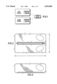
- FIG. 2 is a side view of a preferred embodiment of the apparatus of FIG. 1 in an unfolded state.
- the first housing 20 and the second housing 22 are generally planar.
- the first housing 20 has two major surfaces 34 and 36 that are generally planar.
- the second housing 22 has two major surfaces 40 and 42 that are generally planar.
- the first housing 20 and the second housing 22 are generally coplanar.
- the major surface 34 is generally flush with the major surface 40
- the major surface 36 is generally flush with the major surface 42 in the unfolded state.
- a hinge 44 pivotally connects the first housing 20 to the second housing 22.
- the hinge 44 includes a bearing 46 and a bearing 48.
- the bearing 46 is parallel to the bearing 48.
- the bearing 46 receives and retains a journal such as a pin 50 proximate to an edge 52 of the first housing 20.
- the bearing 48 receives and retains a journal such as a pin 54 proximate to an edge 56 of the second housing 22.
- the first housing 20 is pivotable about an axis through the bearing 46.
- the second housing 22 is pivotable about an axis through the bearing 48. In this way, the first housing 20 and the second housing 22 are pivotally connected at the edges 52 and 56, respectively. It is noted that alternative hinges can be employed to pivotally connect the first housing 20 to the second housing 22.
- the apparatus In the unfolded state, the apparatus has a footprint (i.e. a periphery) similar to a card such as a credit card.
- the apparatus To fit within a card-receiving slot in a typical wallet, the apparatus has a first dimension 60 of about 3.75 inches or less, and a second dimension 62 of about 2.75 inches or less.
- the first dimension 60 is about 3.375 inches and the second dimension 62 is about 2.125 inches.
- the first housing 20, the second housing 22, and the hinge 44 are formed of a fine-finished alloy.
- the first housing 20, the second housing 22, and the hinge 44 can be formed of plastic such as injection molded ABS/PC. It is noted that the first housing 20, the second housing 22, and the hinge 44 can be formed of alternative materials using alternative processes.
- the apparatus includes an optical reader having an emitter and a detector housed or otherwise supported by the housing.
- the emitter emits light near a corner portion 64 adjacent the edge 52.
- the detector detects light near a corner portion 66 adjacent the edge 56.
- the corner portions 64 and 66 are formed of a transparent acrylic material to allow optical signals to communicate therethrough.
- a button pad 68 is supported at a face of the first housing 20 defined by the major surface 34.
- a button pad 70 is supported at a face of the second housing 22 defined by the major surface 40. The button pads 68 and 70 are depressed by the end user to control the activation and the deactivation of the optical reader.
- FIG. 3 is a side view of the apparatus of FIG. 2 in a folded state. In the folded state, the first housing 20 and the second housing 22 are no longer coplanar. In the view of FIG. 3, the second housing 22 is located behind the first housing 20.
- the apparatus assumes a form amenable for reading optical data from the external device 30.
- an end user grasps the apparatus in a manner similar to grasping a writing implement such as a pen, a pencil, or a stylus.
- the user depresses one or both of the button pads 68 and 70 to activate the optical reader.
- the user swipes the corner portions 64 and 66 across printed data, such as a bar code, from a substrate such as paper.
- the user releases one or both of the button pads 68 and 70 to deactivate the optical reader. In this way, the printed data is optically read by the apparatus.
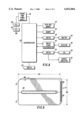
- FIG. 4 is an end view of the apparatus of FIG. 2 in a first folded state.
- the major surface 36 of the first housing 20 contacts the major surface 42 of the second housing 22.
- the first housing 20 and the second housing 22 are generally parallel in the first folded state.
- FIG. 5 is an end view of the apparatus of FIG. 2 in a second folded state.
- the major surface 36 of the first housing 20 is separated from the major surface 42 of the second housing 22. Consequently, the apparatus assumes a non-planar, V-shaped form wherein the first housing 20 is transverse to the second housing 22.
- the non-planar, V-shaped form may be easier to grasp and manipulate for some users in comparison to the first folded state described with reference to FIG. 4.
- an angle 72 between the first housing 20 and the second housing 22 is greater than or equal to 15°.
- the angle 72 can be constrained by the hinge 74 and/or by portions of the first housing 20 and the second housing 22.
- FIG. 6 is a side view of an alternative embodiment of the apparatus of FIG. 1 in an unfolded state.
- the first housing 20 and the second housing 22 are generally planar, and are generally coplanar in the unfolded state.
- the apparatus In the unfolded state, the apparatus has a card-shaped periphery such as those described with reference to FIGS. 1 and 2.
- a hinge 74 pivotally connects the first housing 20 to the second housing 22.
- the hinge 74 is equivalent to the hinge 44 described with reference to FIG. 2.
- the first housing 20 and the second housing 22 are pivotally connected at edges 76 and 80, respectively.
- the apparatus include an optical reader having an emitter and a detector housed or otherwise supported by the housing.
- the emitter emits light near a corner portion 86 adjacent an edge 90 opposite the edge 76.
- the detector detects light near a corner portion 92 adjacent an edge 94 opposite the edge 80.
- the corner portions 86 and 92 are formed of a transparent acrylic material to allow optical signals to communicate therethrough.
- FIG. 7 is a side view of the apparatus of FIG. 6 in a folded state.
- the second housing 22 is located behind the first housing 20.
- an end view of the apparatus in the folded state is similar to one illustrated in FIG. 4.
- the first housing 20 and the second housing 22 are no longer coplanar, but are generally parallel.
- a major surface 94 of the first housing 20 contacts a major surface 96 of the second housing 22 in the folded state.
- the apparatus assumes a form amenable for reading optical data from the external device 30.
- an end user grasps the apparatus in a manner similar to grasping a writing implement such as a pen, a pencil, or a stylus. While grasping the apparatus, the user depresses one or both of button pads 100 and 102 to activate the optical reader. Thereafter, the user swipes the corner portions 86 and 92 across printed data, such as a bar code, from a substrate such as paper. After reading the printed data, the user releases one or both of the button pads 100 and 102 to deactivate the optical reader. In this way, printed data is optically read using the apparatus.
- FIG. 8 is a block diagram of an embodiment of an optical reader circuit.
- the optical reader circuit is housed or otherwise supported by the first housing 20 and/or the second housing 22 of the apparatus.
- a microprocessor 130 directs the operation of the circuit in accordance with routines stored in a read-only memory 132.
- the read-only memory 132 includes a bar code driver routine and a data communication routine.
- An emitter 134 which preferably includes an infrared light-emitting diode, is responsive to the microprocessor 130 via a buffer 136.
- a detector 140 which preferably includes an infrared photodiode, is coupled to the microprocessor 130 by an analog signal discriminator 142.
- the emitter 134, the detector 140, the buffer 136, and the analog signal discriminator 142 are included in an IrDA (Infrared Data Association)-compliant transceiver.
- IrDA Infrared Data Association
- the microprocessor 130 drives the emitter 134 to illuminate a portion of a bar code.
- the microprocessor 130 reads data associated with a portion of the bar code from the detector 140. After reading the bar code, the microprocessor 130 decodes data encoded by the bar code.
- the microprocessor 130 stores either the encoded data or the decoded data in a memory 144.
- the memory 144 includes a nonvolatile memory device such as an EEPROM to maintain the data in the absence of a powering signal.
- the microprocessor 130 drives the emitter 134 to communicate data stored in the memory 144.
- the data communication routine is compliant with an IrDA data communication protocol such as the 9600 baud IrDA protocol.
- IrDA data communication protocol such as the 9600 baud IrDA protocol.
- data can be communicated with another like optical reading apparatus, or with other devices having an IrDA interface such as notebook computers, palmtop computers, and personal digital assistants.
- the microprocessor 130 decodes data received by the detector 140.
- the data is decoded in accordance with an IrDA protocol.
- the microprocessor 130 can store the data in the memory 144.
- the data can include data read from a like optical reading apparatus, or a routine executable by the microprocessor 130 to provide additional functionality.
- the microprocessor 130 is responsive to a sensor such as a switch 146 to activate and deactivate the optical code reading and data communication features of the circuit.
- the switch 146 senses a user-initiated depression and release of the button pads described herein.
- One or more indicators are responsive to the microprocessor 130 via a buffer 154.
- the one or more indicators indicate the status of the circuit.
- a charge pump power supply 156 regulates a series combination of cells 160 and 162 to power the various components of the circuit.
- the charge pump power supply 156 includes a voltage regulator and other associated components.
- the cells 160 and 162 include coin cells such as CR2016 lithium coin cells.
- FIG. 9 is a view of an alternative embodiment of the apparatus of FIG. 1 in an unfolded state.
- the first housing 20 and the second housing 22 are pivotally connected by a hinge 180.
- the housing In the unfolded state, the housing has a periphery which is shaped and sized in accordance with a PCMCIA (Personal Computer Memory Card International Association) form standard.
- the housing has a length 182 of about 85.6 mm, a width 184 of about 54.0 mm, and a thickness 186 dependent upon the PCMCIA type.
- the thickness 186 is about 3.3 mm for Type I, 5.0 mm for Type II, and 10.5 mm for Type III.
- the interface 24 comprises a PCMCIA bus connector.
- the interface 24 includes sixty-eight connectors which mate with sixty-eight pins in a mating connector associated with the external device 30.
- thirty-four connectors 190 are supported by the first housing 20 and thirty-four connectors 192 are supported by the second housing 22.
- the foldable PCMCIA card can include a circuit such as a modem, a memory, or another peripheral associated with PCMCIA cards.
- the foldable PCMCIA card includes an optical reader such as those described herein.
- the PCMCIA interface is in communication with the microprocessor 130 described with reference to FIG. 8.
- the microprocessor 130 is operative to direct data read by the optical reader (and optionally, stored in the memory 144) to be communicated via the PCMCIA interface, and to direct data received via the PCMCIA interface (and optionally, stored in the memory 144) to be communicated via the emitter 134.
- a preferred form of an optical reading apparatus having a PCMCIA interface is described with reference to FIGS. 10 to 13.
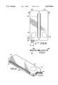
- FIG. 10 is an top view of an alternative embodiment of a housing for an optical reading apparatus.
- the housing includes a first housing 200 and the second housing 202 which are pivotally connected by a hinge 204.
- the apparatus In an unfolded state, the apparatus has a generally planar, card-shaped form such as those described with reference to FIGS. 1 and 2.
- a light-communicating member 206 communicates light between the external device 30 and the optical reader housed by the housing.
- the light-communicating member 206 receives a first optical signal associated with the optical data from the external device 30.
- the light-communicating member 206 communicates the first optical signal to a detector of the optical reader.
- the light-communicating member 206 further communicates a second optical signal from a detector of the optical reader to the external device 30.
- the second optical signal can illuminate the optical data to assist in forming the first optical signal.
- the second optical signal can be used to communicate data to the external device 30.
- the light-communicating member 206 has a form of a portion of a disk bounded by a first radial end 210, a second radial end 212, and an arcuate end 214.
- the length of the radial ends 210 and 212 is about 0.25 inches.
- the arcuate end 214 sweeps an angle of approximately 90°.
- the light-communicating member 206 be formed of a transparent acrylic material.
- the light-communicating member 206 articulates about an axis 216 transverse to (and preferably normal to) the first housing 200 at a pivot point 218. When pivoted to a first position, the light-communicating member 206 is housed by a void 220 defined by the first housing 200. In the first position, the second radial end 212 is generally flush with an edge 222 of the first housing 200.
- the light-communicating member 206 projects beyond the first housing 200.
- the second radial end 212 is transverse to the edge 222.
- the first radial end 210 is generally parallel to the edge 222
- the second radial end 212 is generally perpendicular to the edge 222 in the second position.
- the apparatus includes a PCMCIA interface at an edge 224 and an edge 226 opposite to the edge 222.
- the PCMCIA interface is integrated with the apparatus in accordance with the teachings of FIG. 9.
- FIG. 11 is an end view of the housing of FIG. 10 in an unfolded state.
- the first housing 200 and the second housing 202 are generally planar, and are generally coplanar with each other.
- FIG. 12 is an isometric view of the housing of FIG. 10 in a folded state.
- the apparatus assumes a form amenable for reading optical data from the external device 30.
- an end user grasps the apparatus in a manner similar to grasping a writing implement such as a pen, a pencil, or a stylus.
- the user depresses one or both of button pads 230 and 232 to activate the optical reader.
- the user swipes the light-communicating member 206 across printed data, such as a bar code, from a substrate such as paper.
- the user releases one or both of the button pads 230 and 232 to deactivate the optical reader.
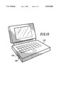
- FIG. 13 is a view of the housing of FIG. 10 inserted into a PCMCIA socket 240 of a computer 242.
- the PCMCIA interface of the apparatus mates with a PCMCIA interface in the PCMCIA socket 240.
- the light-communicating member 206 is pivoted to project from the PCMCIA socket 240.
- optical signals can be communicated between the computer 242 and a peripheral. Examples of peripherals include printers, remote controllers, handheld computers, personal digital assistants, and other devices having an infrared interface such as an IrDA interface.
- the various embodiments of the present invention incorporate an optical reader with a foldable card-shaped housing, they provide a significant improvement in that the apparatus can be stored in a card holder (such as in a wallet, a purse, a daily planner, or a portfolio) when in an unfolded state, and can be grasped like a writing implement to optically read data when in a folded state. Constraining the housing to be V-shaped in the folded state may facilitate ease in grasping and manipulating the apparatus when optically reading data.
- the foldable PCMCIA card can include an optical reader to provide an optical-to-PCMCIA interface.
- data can be communicated with external devices using optoelectronic devices of the optical reader or with the PCMCIA interface.
Abstract
Description
Claims (19)
Priority Applications (1)
| Application Number | Priority Date | Filing Date | Title |
|---|---|---|---|
| US08/926,792 US6032866A (en) | 1997-09-10 | 1997-09-10 | Foldable apparatus having an interface |
Applications Claiming Priority (1)
| Application Number | Priority Date | Filing Date | Title |
|---|---|---|---|
| US08/926,792 US6032866A (en) | 1997-09-10 | 1997-09-10 | Foldable apparatus having an interface |
Publications (1)
| Publication Number | Publication Date |
|---|---|
| US6032866A true US6032866A (en) | 2000-03-07 |
Family
ID=25453728
Family Applications (1)
| Application Number | Title | Priority Date | Filing Date |
|---|---|---|---|
| US08/926,792 Expired - Lifetime US6032866A (en) | 1997-09-10 | 1997-09-10 | Foldable apparatus having an interface |
Country Status (1)
| Country | Link |
|---|---|
| US (1) | US6032866A (en) |
Cited By (48)
| Publication number | Priority date | Publication date | Assignee | Title |
|---|---|---|---|---|
| US6266240B1 (en) * | 1999-02-04 | 2001-07-24 | Palm, Inc. | Encasement for a handheld computer |
| US6356442B1 (en) | 1999-02-04 | 2002-03-12 | Palm, Inc | Electronically-enabled encasement for a handheld computer |
| US6356443B2 (en) | 1999-11-30 | 2002-03-12 | Palm, Inc. | Handheld computer configured for attachment with an external device |
| US6388877B1 (en) | 1999-02-04 | 2002-05-14 | Palm, Inc. | Handheld computer with open accessory slot |
| US6388870B1 (en) | 1999-02-04 | 2002-05-14 | Palm, Inc. | Housing for a handheld computer |
| US6418325B1 (en) * | 1999-07-12 | 2002-07-09 | Motorola, Inc. | Handheld device having an optical data reader |
| US6424722B1 (en) * | 1997-01-13 | 2002-07-23 | Micro Ear Technology, Inc. | Portable system for programming hearing aids |
| US6532148B2 (en) | 1999-11-30 | 2003-03-11 | Palm, Inc. | Mechanism for attaching accessory devices to handheld computers |
| US20030112476A1 (en) * | 2001-12-14 | 2003-06-19 | Chen Wen Shu | Business card scanner |
| US20040089724A1 (en) * | 2002-11-07 | 2004-05-13 | Ellen Lasch | Foldable transaction card |
| US20040169087A1 (en) * | 2002-12-11 | 2004-09-02 | Ellen Lasch | Foldable transaction card systems |
| US20040204921A1 (en) * | 1998-01-09 | 2004-10-14 | Micro Ear Technology, Inc., D/B/A Micro-Tech. | Portable hearing-related analysis system |
| US20050008175A1 (en) * | 1997-01-13 | 2005-01-13 | Hagen Lawrence T. | Portable system for programming hearing aids |
| US6865076B2 (en) | 1999-02-04 | 2005-03-08 | Palmone, Inc. | Electronically-enabled housing apparatus for a computing device |
| US20050205665A1 (en) * | 2003-12-10 | 2005-09-22 | Ellen Lasch | Foldable transaction card systems for non-traditionally-sized transaction cards |
| US20050283263A1 (en) * | 2000-01-20 | 2005-12-22 | Starkey Laboratories, Inc. | Hearing aid systems |
| US7054957B2 (en) | 1997-01-13 | 2006-05-30 | Micro Ear Technology, Inc. | System for programming hearing aids |
| US7070095B1 (en) | 2002-11-07 | 2006-07-04 | American Express Travel Related Services Company, Inc. | Foldable transaction cards and methods of making the same |
| US7137552B1 (en) * | 2003-12-10 | 2006-11-21 | American Express Travel Related Services Company, Inc. | Portable electronic devices interconnected with convenient or foldable transaction cards |
| US7194038B1 (en) * | 1998-10-29 | 2007-03-20 | Nokia Corporation | Method for data communication between a wireless device and an electric device, and a data communication device |
| US20070081303A1 (en) * | 2005-10-11 | 2007-04-12 | Lawrence Lam | Recess housing feature for computing devices |
| US7209113B2 (en) * | 2002-05-09 | 2007-04-24 | Gateway Inc. | Stylus pen expansion slot |
| US7278584B1 (en) * | 2002-11-07 | 2007-10-09 | American Express Travel Related Services Company, Inc. | Portable electronic music devices with convenient or foldable transaction cards |
| US20070241186A1 (en) * | 2006-04-14 | 2007-10-18 | Lindahl Kim O | Stored-value card with chamber |
| US20090014110A1 (en) * | 2002-11-07 | 2009-01-15 | American Express Travel Related Services Company, Inc. | Foldable transaction cards and methods of making the same |
| US20090039154A1 (en) * | 2003-12-10 | 2009-02-12 | American Express Travel Related Services Company, Inc. | Foldable transaction card systems |
| US20090058812A1 (en) * | 2007-08-30 | 2009-03-05 | Yoshimichi Matsuoka | Mobile computing device construction using front paneled assembly and components thereof |
| US20090059495A1 (en) * | 2007-08-30 | 2009-03-05 | Yoshimichi Matsuoka | Housing construction for mobile computing device |
| US7631812B2 (en) | 2003-12-10 | 2009-12-15 | Williams Troy P | Foldable transaction card systems |
| US7668750B2 (en) | 2001-07-10 | 2010-02-23 | David S Bonalle | Securing RF transactions using a transactions counter |
| US7690577B2 (en) | 2001-07-10 | 2010-04-06 | Blayn W Beenau | Registering a biometric for radio frequency transactions |
| USD613743S1 (en) | 2007-08-30 | 2010-04-13 | Palm, Inc. | Mobile computing device |
| US7705732B2 (en) | 2001-07-10 | 2010-04-27 | Fred Bishop | Authenticating an RF transaction using a transaction counter |
| US7725427B2 (en) | 2001-05-25 | 2010-05-25 | Fred Bishop | Recurrent billing maintenance with radio frequency payment devices |
| US7793845B2 (en) | 2004-07-01 | 2010-09-14 | American Express Travel Related Services Company, Inc. | Smartcard transaction system and method |
| US7886157B2 (en) | 2001-07-10 | 2011-02-08 | Xatra Fund Mx, Llc | Hand geometry recognition biometrics on a fob |
| US7889052B2 (en) | 2001-07-10 | 2011-02-15 | Xatra Fund Mx, Llc | Authorizing payment subsequent to RF transactions |
| US20110193787A1 (en) * | 2010-02-10 | 2011-08-11 | Kevin Morishige | Input mechanism for providing dynamically protruding surfaces for user interaction |
| US8001054B1 (en) | 2001-07-10 | 2011-08-16 | American Express Travel Related Services Company, Inc. | System and method for generating an unpredictable number using a seeded algorithm |
| USRE43157E1 (en) | 2002-09-12 | 2012-02-07 | Xatra Fund Mx, Llc | System and method for reassociating an account number to another transaction account |
| US8284025B2 (en) | 2001-07-10 | 2012-10-09 | Xatra Fund Mx, Llc | Method and system for auditory recognition biometrics on a FOB |
| US8300862B2 (en) | 2006-09-18 | 2012-10-30 | Starkey Kaboratories, Inc | Wireless interface for programming hearing assistance devices |
| USRE45416E1 (en) | 2001-07-10 | 2015-03-17 | Xatra Fund Mx, Llc | Processing an RF transaction using a routing number |
| US9024719B1 (en) | 2001-07-10 | 2015-05-05 | Xatra Fund Mx, Llc | RF transaction system and method for storing user personal data |
| US9031880B2 (en) | 2001-07-10 | 2015-05-12 | Iii Holdings 1, Llc | Systems and methods for non-traditional payment using biometric data |
| US9454752B2 (en) | 2001-07-10 | 2016-09-27 | Chartoleaux Kg Limited Liability Company | Reload protocol at a transaction processing entity |
| US11182663B1 (en) * | 2019-09-12 | 2021-11-23 | United Services Automobile Association (Usaa) | Foldable chip card with improved security |
| US11599756B1 (en) * | 2019-09-12 | 2023-03-07 | United Services Automobile Association (Usaa) | Flexible foldable chip card with improved security |
Citations (18)
| Publication number | Priority date | Publication date | Assignee | Title |
|---|---|---|---|---|
| US4721849A (en) * | 1985-10-02 | 1988-01-26 | Videx, Inc. | Portable programmable optical code reader |
| US4801789A (en) * | 1986-07-07 | 1989-01-31 | Videx, Inc. | Replaceable reader head for optical code reader |
| US4803474A (en) * | 1986-03-18 | 1989-02-07 | Fischer & Porter Company | Cursor control matrix for computer graphics |
| US4916441A (en) * | 1988-09-19 | 1990-04-10 | Clinicom Incorporated | Portable handheld terminal |
| US5153590A (en) * | 1991-02-04 | 1992-10-06 | Motorola, Inc. | Keypad apparatus |
| US5175759A (en) * | 1989-11-20 | 1992-12-29 | Metroka Michael P | Communications device with movable element control interface |
| US5331136A (en) * | 1990-01-18 | 1994-07-19 | Norand Corporation | Hand-held data capture system with interchangeable modules |
| US5373149A (en) * | 1993-02-01 | 1994-12-13 | At&T Bell Laboratories | Folding electronic card assembly |
| US5384910A (en) * | 1992-12-31 | 1995-01-24 | International Business Machines Corporation | Method and apparatus for facilitating operator reconfiguration of a graphical user interface in a data processing system |
| US5386568A (en) * | 1992-12-01 | 1995-01-31 | Yamaha Corporation | Apparatus and method for linking software modules |
| US5410141A (en) * | 1989-06-07 | 1995-04-25 | Norand | Hand-held data capture system with interchangable modules |
| US5416310A (en) * | 1993-05-28 | 1995-05-16 | Symbol Technologies, Inc. | Computer and/or scanner system incorporated into a garment |
| US5468952A (en) * | 1992-05-15 | 1995-11-21 | Symbol Technologies, Inc. | Miniature high speed scan element mounted on a personal computer interface card |
| US5539807A (en) * | 1992-02-19 | 1996-07-23 | Telefonaktiebolaget Lm Ericsson | System and method for directing call charges to third parties |
| US5552806A (en) * | 1994-04-29 | 1996-09-03 | Motorola, Inc. | Method and apparatus for positioning selectable function icons on a display |
| US5656804A (en) * | 1992-06-03 | 1997-08-12 | Symbol Technologies, Inc. | Apparatus and method for sensing motion of a portable terminal |
| US5734371A (en) * | 1994-12-19 | 1998-03-31 | Lucent Technologies Inc. | Interactive pointing device |
| US5834749A (en) * | 1994-08-30 | 1998-11-10 | Durbin; Dennis A. | Optical image capture system for reading targets at oblique angles |
-
1997
- 1997-09-10 US US08/926,792 patent/US6032866A/en not_active Expired - Lifetime
Patent Citations (18)
| Publication number | Priority date | Publication date | Assignee | Title |
|---|---|---|---|---|
| US4721849A (en) * | 1985-10-02 | 1988-01-26 | Videx, Inc. | Portable programmable optical code reader |
| US4803474A (en) * | 1986-03-18 | 1989-02-07 | Fischer & Porter Company | Cursor control matrix for computer graphics |
| US4801789A (en) * | 1986-07-07 | 1989-01-31 | Videx, Inc. | Replaceable reader head for optical code reader |
| US4916441A (en) * | 1988-09-19 | 1990-04-10 | Clinicom Incorporated | Portable handheld terminal |
| US5410141A (en) * | 1989-06-07 | 1995-04-25 | Norand | Hand-held data capture system with interchangable modules |
| US5175759A (en) * | 1989-11-20 | 1992-12-29 | Metroka Michael P | Communications device with movable element control interface |
| US5331136A (en) * | 1990-01-18 | 1994-07-19 | Norand Corporation | Hand-held data capture system with interchangeable modules |
| US5153590A (en) * | 1991-02-04 | 1992-10-06 | Motorola, Inc. | Keypad apparatus |
| US5539807A (en) * | 1992-02-19 | 1996-07-23 | Telefonaktiebolaget Lm Ericsson | System and method for directing call charges to third parties |
| US5468952A (en) * | 1992-05-15 | 1995-11-21 | Symbol Technologies, Inc. | Miniature high speed scan element mounted on a personal computer interface card |
| US5656804A (en) * | 1992-06-03 | 1997-08-12 | Symbol Technologies, Inc. | Apparatus and method for sensing motion of a portable terminal |
| US5386568A (en) * | 1992-12-01 | 1995-01-31 | Yamaha Corporation | Apparatus and method for linking software modules |
| US5384910A (en) * | 1992-12-31 | 1995-01-24 | International Business Machines Corporation | Method and apparatus for facilitating operator reconfiguration of a graphical user interface in a data processing system |
| US5373149A (en) * | 1993-02-01 | 1994-12-13 | At&T Bell Laboratories | Folding electronic card assembly |
| US5416310A (en) * | 1993-05-28 | 1995-05-16 | Symbol Technologies, Inc. | Computer and/or scanner system incorporated into a garment |
| US5552806A (en) * | 1994-04-29 | 1996-09-03 | Motorola, Inc. | Method and apparatus for positioning selectable function icons on a display |
| US5834749A (en) * | 1994-08-30 | 1998-11-10 | Durbin; Dennis A. | Optical image capture system for reading targets at oblique angles |
| US5734371A (en) * | 1994-12-19 | 1998-03-31 | Lucent Technologies Inc. | Interactive pointing device |
Non-Patent Citations (2)
| Title |
|---|
| DatO Patented Pointing Gesture System by Evan Graham Ph.D., White Paper, 20 pp., Mar. 3, 1997. * |
| DatO™ Patented Pointing Gesture System by Evan Graham Ph.D., White Paper, 20 pp., Mar. 3, 1997. |
Cited By (78)
| Publication number | Priority date | Publication date | Assignee | Title |
|---|---|---|---|---|
| US6424722B1 (en) * | 1997-01-13 | 2002-07-23 | Micro Ear Technology, Inc. | Portable system for programming hearing aids |
| US20100086153A1 (en) * | 1997-01-13 | 2010-04-08 | Micro Ear Technology, Inc. D/B/A Micro-Tech | Portable system for programming hearing aids |
| US7787647B2 (en) | 1997-01-13 | 2010-08-31 | Micro Ear Technology, Inc. | Portable system for programming hearing aids |
| US7929723B2 (en) | 1997-01-13 | 2011-04-19 | Micro Ear Technology, Inc. | Portable system for programming hearing aids |
| US20050008175A1 (en) * | 1997-01-13 | 2005-01-13 | Hagen Lawrence T. | Portable system for programming hearing aids |
| US20020168075A1 (en) * | 1997-01-13 | 2002-11-14 | Micro Ear Technology, Inc. | Portable system programming hearing aids |
| US7054957B2 (en) | 1997-01-13 | 2006-05-30 | Micro Ear Technology, Inc. | System for programming hearing aids |
| US20050196002A1 (en) * | 1997-01-13 | 2005-09-08 | Micro Ear Technology, Inc., D/B/A Micro-Tech | Portable system for programming hearing aids |
| US20040204921A1 (en) * | 1998-01-09 | 2004-10-14 | Micro Ear Technology, Inc., D/B/A Micro-Tech. | Portable hearing-related analysis system |
| US7194038B1 (en) * | 1998-10-29 | 2007-03-20 | Nokia Corporation | Method for data communication between a wireless device and an electric device, and a data communication device |
| US8867631B2 (en) | 1998-10-29 | 2014-10-21 | Memory Technologies Llc | Method for data communication between a wireless and an electronic device, and a data communication device |
| US9277350B2 (en) | 1998-10-29 | 2016-03-01 | Memory Technologies Llc | Method for data communication between a wireless device and a electronic device, and a data communication device |
| US20070259622A1 (en) * | 1998-10-29 | 2007-11-08 | Sami Inkinen | Method for Data Communication between a Wireless Device and an Electronic Device, and a Data Communication Device |
| US6865076B2 (en) | 1999-02-04 | 2005-03-08 | Palmone, Inc. | Electronically-enabled housing apparatus for a computing device |
| US6388870B1 (en) | 1999-02-04 | 2002-05-14 | Palm, Inc. | Housing for a handheld computer |
| US20070279859A1 (en) * | 1999-02-04 | 2007-12-06 | Canova Francis J Jr | Handheld computer |
| US9367083B2 (en) | 1999-02-04 | 2016-06-14 | Hewlett-Packard Development Company, L.P. | Computing device housing |
| US6356442B1 (en) | 1999-02-04 | 2002-03-12 | Palm, Inc | Electronically-enabled encasement for a handheld computer |
| US6388877B1 (en) | 1999-02-04 | 2002-05-14 | Palm, Inc. | Handheld computer with open accessory slot |
| US7061762B2 (en) | 1999-02-04 | 2006-06-13 | Palm, Inc. | Housing for a computing apparatus |
| US8804332B2 (en) | 1999-02-04 | 2014-08-12 | Hewlett-Packard Development Company, L.P. | Handheld computer |
| US6266240B1 (en) * | 1999-02-04 | 2001-07-24 | Palm, Inc. | Encasement for a handheld computer |
| US6418325B1 (en) * | 1999-07-12 | 2002-07-09 | Motorola, Inc. | Handheld device having an optical data reader |
| US6356443B2 (en) | 1999-11-30 | 2002-03-12 | Palm, Inc. | Handheld computer configured for attachment with an external device |
| US6532148B2 (en) | 1999-11-30 | 2003-03-11 | Palm, Inc. | Mechanism for attaching accessory devices to handheld computers |
| US8503703B2 (en) | 2000-01-20 | 2013-08-06 | Starkey Laboratories, Inc. | Hearing aid systems |
| US9344817B2 (en) | 2000-01-20 | 2016-05-17 | Starkey Laboratories, Inc. | Hearing aid systems |
| US20050283263A1 (en) * | 2000-01-20 | 2005-12-22 | Starkey Laboratories, Inc. | Hearing aid systems |
| US9357317B2 (en) | 2000-01-20 | 2016-05-31 | Starkey Laboratories, Inc. | Hearing aid systems |
| US7725427B2 (en) | 2001-05-25 | 2010-05-25 | Fred Bishop | Recurrent billing maintenance with radio frequency payment devices |
| US8001054B1 (en) | 2001-07-10 | 2011-08-16 | American Express Travel Related Services Company, Inc. | System and method for generating an unpredictable number using a seeded algorithm |
| US8548927B2 (en) | 2001-07-10 | 2013-10-01 | Xatra Fund Mx, Llc | Biometric registration for facilitating an RF transaction |
| US9454752B2 (en) | 2001-07-10 | 2016-09-27 | Chartoleaux Kg Limited Liability Company | Reload protocol at a transaction processing entity |
| US7668750B2 (en) | 2001-07-10 | 2010-02-23 | David S Bonalle | Securing RF transactions using a transactions counter |
| US9031880B2 (en) | 2001-07-10 | 2015-05-12 | Iii Holdings 1, Llc | Systems and methods for non-traditional payment using biometric data |
| US9024719B1 (en) | 2001-07-10 | 2015-05-05 | Xatra Fund Mx, Llc | RF transaction system and method for storing user personal data |
| USRE45416E1 (en) | 2001-07-10 | 2015-03-17 | Xatra Fund Mx, Llc | Processing an RF transaction using a routing number |
| US7690577B2 (en) | 2001-07-10 | 2010-04-06 | Blayn W Beenau | Registering a biometric for radio frequency transactions |
| US8284025B2 (en) | 2001-07-10 | 2012-10-09 | Xatra Fund Mx, Llc | Method and system for auditory recognition biometrics on a FOB |
| US7705732B2 (en) | 2001-07-10 | 2010-04-27 | Fred Bishop | Authenticating an RF transaction using a transaction counter |
| US7889052B2 (en) | 2001-07-10 | 2011-02-15 | Xatra Fund Mx, Llc | Authorizing payment subsequent to RF transactions |
| US7886157B2 (en) | 2001-07-10 | 2011-02-08 | Xatra Fund Mx, Llc | Hand geometry recognition biometrics on a fob |
| US20030112476A1 (en) * | 2001-12-14 | 2003-06-19 | Chen Wen Shu | Business card scanner |
| US7209113B2 (en) * | 2002-05-09 | 2007-04-24 | Gateway Inc. | Stylus pen expansion slot |
| USRE43157E1 (en) | 2002-09-12 | 2012-02-07 | Xatra Fund Mx, Llc | System and method for reassociating an account number to another transaction account |
| US7540426B1 (en) * | 2002-11-07 | 2009-06-02 | American Express Travel Related Services Company, Inc. | Foldable transaction cards and methods of making the same |
| US20040089724A1 (en) * | 2002-11-07 | 2004-05-13 | Ellen Lasch | Foldable transaction card |
| US7278584B1 (en) * | 2002-11-07 | 2007-10-09 | American Express Travel Related Services Company, Inc. | Portable electronic music devices with convenient or foldable transaction cards |
| US7213764B2 (en) | 2002-11-07 | 2007-05-08 | American Express Travel Related Services Company, Inc. | Foldable transaction card |
| US7398931B2 (en) | 2002-11-07 | 2008-07-15 | American Express Travel Related Services Company, Inc. | Foldable transaction card |
| US7070095B1 (en) | 2002-11-07 | 2006-07-04 | American Express Travel Related Services Company, Inc. | Foldable transaction cards and methods of making the same |
| US7520439B1 (en) | 2002-11-07 | 2009-04-21 | American Express Travel Related Services Company, Inc. | Portable electronic devices with convenient or foldable transaction cards |
| US20090014110A1 (en) * | 2002-11-07 | 2009-01-15 | American Express Travel Related Services Company, Inc. | Foldable transaction cards and methods of making the same |
| US7892371B2 (en) | 2002-11-07 | 2011-02-22 | American Express Travel Related Services Company, Inc. | Foldable transaction cards and methods of making the same |
| US20070069034A1 (en) * | 2002-12-11 | 2007-03-29 | Ellen Lasch | Foldable transaction card systems |
| US20040169087A1 (en) * | 2002-12-11 | 2004-09-02 | Ellen Lasch | Foldable transaction card systems |
| US7147151B2 (en) | 2002-12-11 | 2006-12-12 | American Express Travel Related Services Company, Inc. | Foldable transaction card systems |
| US7347360B2 (en) | 2003-12-10 | 2008-03-25 | American Express Travel Related Services Company, Inc. | Foldable transaction card systems for non-traditionally-sized transaction cards |
| US7721956B2 (en) * | 2003-12-10 | 2010-05-25 | American Express Travel Related Services Company, Inc. | Foldable transaction card systems |
| US20090039154A1 (en) * | 2003-12-10 | 2009-02-12 | American Express Travel Related Services Company, Inc. | Foldable transaction card systems |
| US7631812B2 (en) | 2003-12-10 | 2009-12-15 | Williams Troy P | Foldable transaction card systems |
| US20050205665A1 (en) * | 2003-12-10 | 2005-09-22 | Ellen Lasch | Foldable transaction card systems for non-traditionally-sized transaction cards |
| US7137552B1 (en) * | 2003-12-10 | 2006-11-21 | American Express Travel Related Services Company, Inc. | Portable electronic devices interconnected with convenient or foldable transaction cards |
| US8016191B2 (en) | 2004-07-01 | 2011-09-13 | American Express Travel Related Services Company, Inc. | Smartcard transaction system and method |
| US7793845B2 (en) | 2004-07-01 | 2010-09-14 | American Express Travel Related Services Company, Inc. | Smartcard transaction system and method |
| US20070081303A1 (en) * | 2005-10-11 | 2007-04-12 | Lawrence Lam | Recess housing feature for computing devices |
| US20070241186A1 (en) * | 2006-04-14 | 2007-10-18 | Lindahl Kim O | Stored-value card with chamber |
| US7316357B2 (en) * | 2006-04-14 | 2008-01-08 | Target Brands, Inc. | Stored-value card with bubble wand |
| US20070241197A1 (en) * | 2006-04-14 | 2007-10-18 | Target Brands, Inc. | Stored-value card with bubble wand |
| US7360710B2 (en) | 2006-04-14 | 2008-04-22 | Target Brands, Inc. | Stored-value card with chamber |
| US8300862B2 (en) | 2006-09-18 | 2012-10-30 | Starkey Kaboratories, Inc | Wireless interface for programming hearing assistance devices |
| US20090059495A1 (en) * | 2007-08-30 | 2009-03-05 | Yoshimichi Matsuoka | Housing construction for mobile computing device |
| USD613743S1 (en) | 2007-08-30 | 2010-04-13 | Palm, Inc. | Mobile computing device |
| US8270158B2 (en) | 2007-08-30 | 2012-09-18 | Hewlett-Packard Development Company, L.P. | Housing construction for mobile computing device |
| US20090058812A1 (en) * | 2007-08-30 | 2009-03-05 | Yoshimichi Matsuoka | Mobile computing device construction using front paneled assembly and components thereof |
| US20110193787A1 (en) * | 2010-02-10 | 2011-08-11 | Kevin Morishige | Input mechanism for providing dynamically protruding surfaces for user interaction |
| US11182663B1 (en) * | 2019-09-12 | 2021-11-23 | United Services Automobile Association (Usaa) | Foldable chip card with improved security |
| US11599756B1 (en) * | 2019-09-12 | 2023-03-07 | United Services Automobile Association (Usaa) | Flexible foldable chip card with improved security |
Similar Documents
| Publication | Publication Date | Title |
|---|---|---|
| US6032866A (en) | Foldable apparatus having an interface | |
| US5939702A (en) | Writing implement having an integrated optical reader | |
| US5902991A (en) | Card shaped computer peripheral device | |
| US9886657B2 (en) | System for data card emulation | |
| US11042793B2 (en) | Portable data terminal | |
| US4471218A (en) | Self-contained, portable data entry terminal | |
| US5598487A (en) | Hand-held data entry system removable signature pad | |
| US5744789A (en) | Bar-code reader | |
| US5123064A (en) | Hand-held data entry system and removable signature pad module therefor | |
| US7167158B2 (en) | Scanning electronic book | |
| US6119944A (en) | Down-loadable hand-held optical reader | |
| US6845915B2 (en) | Extended range bar code reader | |
| US7023692B2 (en) | Multifunctional electronic palmtop computer | |
| US5659800A (en) | System for directly sending undecoded raw signals from reader device via external slave interface to personal computer through communication port without first decoding the signals | |
| US20040069851A1 (en) | Radio frequency identification reader with removable media | |
| US20020162891A1 (en) | Writing instrument with laser pointer and bar code reader | |
| WO2002073512A1 (en) | Radio frequency identification reader with removable media | |
| US20040068601A1 (en) | Information input device with multiple memory card reader | |
| US20180307958A1 (en) | System and Method for Reflecting Light | |
| JP3148801U (en) | Mouse input device adopting transflective lens with one-dimensional barcode reading function | |
| WO1999018494A1 (en) | Smartcard terminal | |
| EP1179766A2 (en) | A unit comprising a card read/write device | |
| WO2006008684A1 (en) | Desktop device for writing user data to a transponder | |
| JPH11110473A (en) | Bar code reading device |
Legal Events
| Date | Code | Title | Description |
|---|---|---|---|
| AS | Assignment |
Owner name: MOTOROLA, INC., ILLINOIS Free format text: ASSIGNMENT OF ASSIGNORS INTEREST;ASSIGNORS:KNIGHTON, MARK S.;DROBNIS, DAVID D.;AGABRA, DAVID S.;AND OTHERS;REEL/FRAME:008937/0545 Effective date: 19970905 |
|
| STCF | Information on status: patent grant |
Free format text: PATENTED CASE |
|
| AS | Assignment |
Owner name: WILLIAM REBER, L.L.C., ILLINOIS Free format text: ASSIGNMENT OF ASSIGNORS INTEREST;ASSIGNOR:MOTOROLA, INC.;REEL/FRAME:013288/0298 Effective date: 20020920 |
|
| FPAY | Fee payment |
Year of fee payment: 4 |
|
| AS | Assignment |
Owner name: ADVENTURE GALLERY SOFTWARE LIMITED LIABILITY COMPA Free format text: ASSIGNMENT OF ASSIGNORS INTEREST;ASSIGNOR:WILLIAM REBER L.L.C.;REEL/FRAME:019000/0348 Effective date: 20061002 |
|
| FPAY | Fee payment |
Year of fee payment: 8 |
|
| FEPP | Fee payment procedure |
Free format text: PAYOR NUMBER ASSIGNED (ORIGINAL EVENT CODE: ASPN); ENTITY STATUS OF PATENT OWNER: LARGE ENTITY |
|
| FPAY | Fee payment |
Year of fee payment: 12 |
|
| AS | Assignment |
Owner name: INTELLECTUAL VENTURES I LLC, DELAWARE Free format text: MERGER;ASSIGNOR:ADVENTURE GALLERY SOFTWARE LIMITED LIABILITY COMPANY;REEL/FRAME:036247/0990 Effective date: 20150728 |
|
| AS | Assignment |
Owner name: HANGER SOLUTIONS, LLC, GEORGIA Free format text: ASSIGNMENT OF ASSIGNORS INTEREST;ASSIGNOR:INTELLECTUAL VENTURES ASSETS 161 LLC;REEL/FRAME:052159/0509 Effective date: 20191206 |
|
| AS | Assignment |
Owner name: INTELLECTUAL VENTURES ASSETS 161 LLC, DELAWARE Free format text: ASSIGNMENT OF ASSIGNORS INTEREST;ASSIGNOR:INTELLECTUAL VENTURES I LLC;REEL/FRAME:051945/0001 Effective date: 20191126 |