US6033167A - Honeycomb bag pad - Google Patents
Honeycomb bag pad Download PDFInfo
- Publication number
- US6033167A US6033167A US09/130,252 US13025298A US6033167A US 6033167 A US6033167 A US 6033167A US 13025298 A US13025298 A US 13025298A US 6033167 A US6033167 A US 6033167A
- Authority
- US
- United States
- Prior art keywords
- recess
- pad
- inflatable member
- honeycomb core
- face
- Prior art date
- Legal status (The legal status is an assumption and is not a legal conclusion. Google has not performed a legal analysis and makes no representation as to the accuracy of the status listed.)
- Expired - Fee Related
Links
Images

Classifications
-
- B—PERFORMING OPERATIONS; TRANSPORTING
- B60—VEHICLES IN GENERAL
- B60P—VEHICLES ADAPTED FOR LOAD TRANSPORTATION OR TO TRANSPORT, TO CARRY, OR TO COMPRISE SPECIAL LOADS OR OBJECTS
- B60P7/00—Securing or covering of load on vehicles
- B60P7/06—Securing of load
- B60P7/065—Securing of load by pressurizing or creating a vacuum in a bag, cover or the like
-
- B—PERFORMING OPERATIONS; TRANSPORTING
- B60—VEHICLES IN GENERAL
- B60P—VEHICLES ADAPTED FOR LOAD TRANSPORTATION OR TO TRANSPORT, TO CARRY, OR TO COMPRISE SPECIAL LOADS OR OBJECTS
- B60P7/00—Securing or covering of load on vehicles
- B60P7/06—Securing of load
- B60P7/16—Protecting against shocks
Definitions
- the present invention relates generally to a honeycomb pad for supporting and cushioning an object during shipment and, more particularly to a honeycomb pad with an inflatable member.
- Objects when transported by truck, rail, or other means have a tendency to move about and become damaged during transport.
- most objects such as furniture and palleted items, require packaging material to be placed around them during shipment.
- the packaging material supports and cushions the objects to prevent the objects from vibrations, quick stops and jarring movements.
- rolls of web material such as paper.
- the rolls of web material When the rolls of web material are transported by truck, rail or other transport means, the rolls have a tendency to move. When the rolls move during transport, the rolls tend to become damaged, abraised, pierced and cut.
- U.S. Pat. No. 4,572,716 to West discloses a device for fixing the position of rolls of web material during shipment.
- the West device includes an inflatable member, an opposite angled honeycomb open cell contact pad and a flat honeycomb support pad sandwiched between the inflatable member and contact pad.
- the contact pad engages the vertically stacked rolls of web material, and the combination of the inflatable member, support pad and contact pad support and hold the vertically stacked rolls of web material in position.
- the Bourgeois device includes an inflatable member and a honeycomb pad or spacer.
- the honeycomb spacer has a recess therein which is conformed to receive and cushion the roll of web material.
- the combination of the inflatable member and honeycomb spacer support and hold the vertically stacked rolls of web material in position.
- the inflatable member and honeycomb spacer must be individually positioned between rolls of web material by an operator.
- the combination of honeycomb spacer and inflatable member perform best when the longitudinal center of the inflatable member aligns with the crown of the roll; however, it is often difficult for the operator to position the inflatable member exactly at the desired position.
- Another disadvantage is the honeycomb spacer together with the roll of web material may shift relative to the inflatable member.
- to support and hold the vertically stacked rolls of web material with a diameter of approximately 45 inches requires an inflatable member with a width of at least approximately 30 inches. For larger rolls of web material with a larger diameter such as 58 inches or 70 inches requires an inflatable member with an even larger width which increases the cost of the device.
- an apparatus for supporting and cushioning objects during shipment includes an inflatable member and a pad.
- the pad has a honeycomb core, a front face and a rear face.
- the rear face of the pad has a rear recess adapted to hold the inflatable member.
- the rear recess is bounded by at least two sidewalls that capture and hold the inflatable member within the rear recess.
- the front face of the pad may also include a front recess for cooperatively receiving the surface of the object.
- the front recess may be defined by a portion of the pad in which the honeycomb core has been compressively deformed to a predetermined depth and a predetermined width to cushion the object received in the front recess.
- an apparatus for supporting and cushioning a roll of web material during shipment includes an inflatable member and a pad.
- the pad has a honeycomb core, a front face and a rear face.
- the rear face of the pad has a rear recess adapted to hold the inflatable member.
- the rear recess is bound by at least two sidewalls for capturing and holding the inflatable member within the rear recess.
- the front face of the pad has a generally concave front recess for cooperatively receiving the roll of web material.
- the generally concave front recess is defined by a portion of the pad in which the honeycomb core has been compressively deformed to a predetermined depth and a predetermined width to cushion the roll of web material received in the front recess.
- the assembly includes a spacer and a bag pad.
- the spacer is a honeycomb pad having a front face and a rear face.
- the rear face of the spacer is substantially flat, and front face of the spacer has a generally concave recess for cooperative receiving one of the rolls of web material.
- the bag pad includes an inflatable member and a pad having a front face and a rear face.
- the rear face has a rear recess for holding the inflatable member.
- the front face has a generally concave front recess for cooperatively receiving one of the rolls of web material.
- the spacer and bag pad are placed between the opposed rolls of web material such that the concave front recess of the spacer engages the crown of one of the rolls, and the concave front recess of the bag pad engages the crown of the other roll.
- the rear recess of the spacer engages the rear surface and air bag captured within the rear recess of the bag pad.
- the generally concave front recesses of both the spacer and bag pad may be defined by a portion of the pad in which the honeycomb core has been compressively deformed to a predetermined depth and a predetermined width to cushion the rolls of web material received in the front recesses.
- FIG. 1 is an isometric exploded view of one embodiment of a honeycomb bag pad in accordance with the present invention
- FIG. 2 is a partially broken isometric view of the honeycomb pad illustrated in FIG. 1;
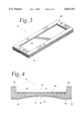
- FIG. 3 is an isometric view of the another embodiment for the honeycomb pad
- FIG. 4 is a cross sectional view of another embodiment for the honeycomb pad
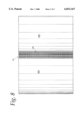
- FIG. 5 is a cross sectional view of an embodiment for the honeycomb pad
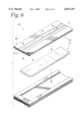
- FIG. 6 is an isometric exploded view of an assembly for supporting and cushioning rolls of web material
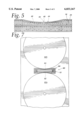
- FIG. 7 is a top plan view of the assembly in FIG. 6 supporting and cushioning vertically stacked rolls of web material.
- FIG. 8 is a side plan view of the assembly in FIG. 6 supporting and cushioning vertically stacked rolls of web material.
- a honeycomb bag pad of the present invention supports and cushions an object during shipment protecting the object from vibrations, quick stops and jarring movements. Additionally, the bag pad of the present invention protects the surface of the object from damage while being shipped. Furthermore, the bag pad of the present invention is easily positioned and aligned with the object when packaging the object for shipment.
- FIG. 1 illustrates one embodiment of a honeycomb bag pad 10 of the present invention.
- the bag pad 10 comprises a pad 12 and an inflatable member or air bag 14.
- the pad 12 is a substantially flat pad of honeycomb material including a honeycomb core 16, a front face 18 and a rear face 20.
- the honeycomb core 16 is comprised of a plurality of honeycomb cells 22 disposed generally perpendicular to the front and rear faces 18 and 20.
- a front face sheet 24 is adhered to the front face 18, and a rear face sheet 26 is adhered to the rear face 20.
- the front and rear face sheets 24 and 26 may be adhered to the front and rear faces 18 and 20 respectively with an adhesive as known to one of ordinary skill in the art.
- the honeycomb core 16 and face sheets 24 and 26 are preferably made of kraft paper, such as fully recyclable and biodegradable kraft paper; however, other materials such as metal foil and plastic sheet may be used. Additionally, the kraft paper may be resin impregnated for water resistance or other properties.
- the rear face 20 of the pad 12 has a rear recess 28.
- the rear recess 28 is adapted to receive and hold the air bag 14.
- the rear recess 28 is defined by three sidewalls 30, 32, and 34.
- the longitudinal sidewalls 30 and 34 position the air bag 14 within the pad 12.
- the width of the rear recess 28 is approximately equal to the width of the air bag 14 to allow the rear recess 28 to hold the air bag 14 within the rear recess 28.
- an adhesive means 36 adheres a front side 38 of the air bag 14 to the surface 40 of the rear recess 28.
- the adhesive means 36 may be any known in the art such as double face tape or glue.
- the pad 12 depicted in FIGS. 1 and 2 is approximately 27 inches wide and 72 inches in length.
- the rear recess 28 is approximately 20 inches wide and 66 inches in length.
- the honeycomb core 16 therein is approximately 4 inches thick from the front face 18 to the rear face 20 of the sidewalls 30, 32 and 34, and the honeycomb core is approximately 2 inches thick from the rear face 20 of the sidewalls 30, 32 and 34 to the surface 40 of the rear recess 28.
- the air bag 14 is a standard air bag with six plies having a width of approximately 18 inches and a length of approximately 60 inches.
- the bag pad 10 is preferably assembled with the air bag 14 in its unexpanded state. Therefore, the front side 38 of the unexpanded air bag 14 is adhered to the surface 40 of the rear recess 28 with the adhesive means 36.
- the bag pad 10 is first positioned, and then the air bag 14 is inflated by the operator. Because the rear recess 28 is bounded on only three sides by the sidewalls 30, 32 and 34, the operator accesses the air bag 14 through the end 42 without a sidewall to inflate the air bag 14.
- FIG. 3 illustrates another embodiment of the pad 12.
- the pad 12 in FIG. 3 includes a fourth sidewall 35 bounding the rear recess 28.
- the four sidewalls 30, 32, 34 and 35 fully capture and hold the air bag 14 within the rear recess 28.
- the pad 12 is approximately 27 inches wide and 72 inches long.
- the rear recess 28 is approximately 20 inches wide and 60 inches in length to capture and hold the 18 inches wide and 60 inches long air bag 14.
- a channel (not shown) may be formed in the fourth sidewall 35 to allow the operator access to inflate the air bag 14.
- the rear recess 28 in the pad 12 is formed by adhering sidewalls 30, 32, and 34 of substantially flat honeycomb panels to another substantially flat honeycomb panel 43.
- the pad 12 may be formed by adhering the sidewalls 30 and 34 each having a width of 3.5 inches, a length of 72 inches and thickness of 2 inches and by adhering the sidewall 32 having a width of 6 inches, length of 20 inches, and thickness of 2 inches, to the honeycomb panel 43 having a width of 27 inches, length of 72 inches and thickness of 2 inches.
- the sidewall panels 30, 32, and 34 may be adhered to the panel 43 using an adhesive such as glue as known to one of ordinary skill in the art.
- the rear recess 28 in the pad 12 is formed by punch cutting a substantially flat honeycomb pad.
- punch cutting the honeycomb core 16 of the pad is simultaneously cut and compressively deformed.
- the method and apparatus for cutting and compressively deforming the honeycomb core is described in U.S. patent application Ser. No. 08/553,582 entitled "Prestressed Honeycomb, Method and Apparatus Therefor" assigned to the present assignee and is incorporated by reference herein.
- a knife means as known in the art, cuts the rear face sheet 26 to outline the sidewalls 30, 32 and 34.
- the honeycomb core 16 of the rear face 20 is then substantially continuously deformed under compressive conditions to a predetermined depth with a die press.
- the honeycomb core may be substantially continuously deformed with incremental compression rollers as is known in the art.
- the pad 12 After compressively deforming the rear face 20 of the pad 12, the surface 40 of the rear recess 28 is bounded by the sidewalls 30, 32 and 34. In this embodiment, because the rear recess 28 is formed by compressively deforming the honeycomb core 16, the pad 12 provides increased shock absorbency. In one embodiment, the pad 12 may comprised honeycomb core 16 having a thickness of approximately 4 inches. After the rear recess 28 has been formed by compressively deforming the honeycomb core 16, the panel is approximately 4 inches thick from the front face 18 to the rear face 20 of the sidewalls 30, 32 and 34, and the honeycomb core is approximately 2 inches thick from the rear face 20 of the sidewalls 30, 32 and 34 to the surface 40 of the rear recess 28.
- the rear recess 28 in the pad 12 is formed by cutting and removing a portion of the honeycomb core 16.
- a series of rotary knife means as known in the art, cut the rear face sheet 26 and adjacent honeycomb core 16 to outline the sidewalls 30, 32 and 34. After completely removing a portion of the honeycomb core 16 adjacent the rear face 20 of the pad 12, the surface 40 of the rear recess 28 is bounded by the sidewalls 30, 32 and 34. Because the rear face sheet 26 of the rear recess 28 was removed by the rotary knife means to form the rear recess 28, a new rear recess face sheet may be adhered to the surface 40 of the rear recess.
- the pad 12 may comprised honeycomb core 16 having a thickness of approximately 4 inches.
- the panel is approximately 4 inches thick from the front face 18 to the rear face 20 of the sidewalls 30, 32 and 34 and approximately 2 inches thick from the front face 18 to the surface 40 of the rear recess 28.
- the front face 18 of the honeycomb pad 12 has a front recess 44.
- the front recess 44 is adapted to conform to the surface of the object that the bag pad supports and protects during shipment.
- the front recess 44 may be conformed to the surface of any object.
- the shaped front recess 44 assists in positioning the bag pad 10 against the object and helps support and cushion the object.
- the front recess 44 substantially aligns with the rear recess 28 on opposite side of the honeycomb pad 12 to transfer the force of the inflated air bag 14 from against the surface 40 of the rear recess 28 to the front recess 44 and thus to the object positioned against the front recess 44.
- the front recess 44 is generally concavely shaped to conform to the surface of an elongate roll of web material (see FIG. 7).
- the front recess 44 is similar to the recess described in U.S. Pat. No. 5,678,968 entitled "Honeycomb Roll Spacer" assigned to the present assignee and is incorporated by reference herein.
- the front recess 44 extends the length of the pad 12 centrally along the longitudinal and central axis A of the pad 12.
- the front recess 44 is designed to contact as much of the length of the roll of web material as possible. As illustrated in FIG.
- the front recess 44 has a bottom concave surface 46 including a centrally disposed elongate aperture 48 defined by a slit 50 that has been cut into the front face sheet 24 and which extends the length of the front recess 44 and pad 12 along and co-linearly with the longitudinal axis A of the pad 12.
- the slit 50 is preferably positioned centrally within the bottom surface 46 of the front recess 44.
- FIG. 5 depicts only one slit 50, additional slits may be cut into the front face sheet 24 in the region of the front recess 44.
- the front recess 44 is defined by a central, longitudinal portion of the pad 12 in which the honeycomb core 16 and front face sheet 24 have been compressively deformed to a predetermined depth using a semi-elliptical shaped die press.
- the method and apparatus for forming the concave recess 44 is more fully described in described in U.S. Pat. No. 5,678,968 entitled “Honeycomb Roll Spacer” assigned to the present assignee and is incorporated by reference herein.
- the front recess 44 may also be formed using elliptical shaped compression rollers. This method and apparatus for forming the concave recess 44 is more fully described in as described in U.S. patent application Ser. No. 08/715,575 entitled "Apparatus for Manufacturing a Roll Spacer" assigned to the present assignee and is incorporated by reference herein.
- the pad 12 is about 27 inches wide and 72 inches long, and the honeycomb core 16 therein is about 4 inches thick from the front face 18 to the rear face 20 at the sidewalls 30, 32 and 34.
- the rear recess 28 is approximately 18 inches wide and 66 inches long, and the honeycomb core 16 of the sidewalls 30, 32 and 34 is approximately 2 inches thick.
- the rear recess 28 accommodates the standard six ply air bag 14 is a standard air bag which is approximately 18 inches wide and 60 inches in length.
- the front recess 44 extends the length of the pad 12 and has a width of about 7 inches and a depth of about 0.5 inch.
- the dimensions of the bag pad 10 may be modified to suit any particular purpose.
- the width of the rear recess 28 and the width of the air bag 14 would preferably remain approximately 18 inches even for larger diameter rolls.
- the width of the rear recess 28 and air bag 14 may maintain this size because the force provided by the air bag 14 is concentrated against the crown of the roll of web material to support any size roll.
- the length of the pad 12 and front recess 44 would be increased to approximately 100 inches long to contact as much of the length of the roll of web material as possible.
- the length of the rear recess 44 and air bag would also be increased to about 97 inches accommodate the longer roll.
- the depth and width of the front recess 44 may be modified to fit any diameter of the roll of web material, for example, the front recess 44 may have a width anywhere between about one fifth the width of the pad 12 to a width which is substantially the entire width of the pad 12.
- the depth of the front recess 44 may be anywhere between about one third of the depth of the honeycomb core 16 to about two thirds the depth of the honeycomb core 16 depending on the size and weight of the roll of web material intended to be cushioned and supported by the bag pad 10.
- the bag pad 10 may be used in an assembly 60 for supporting and cushioning a plurality of vertically disposed rolls of web material 62a and 62b for shipment in a container such as a rail car.
- the assembly 60 as depicted in FIG. 6 comprises a bag pad 10 and an opposed spacer 64.
- the bag pad 10 is as described above.
- the spacer 64 is similar to the pad 12 described above, but the spacer 64 does not have a rear recess. Instead, the spacer 64 has a rear face 66 that is substantially flat.
- the spacer 64 includes a pad 68 of honeycomb core 70 with a front face 72, and the rear face 66.
- the front face 72 has a generally concavely shaped front recess 74 identical to the front recess 44 described above.
- a front face sheet 76 is adhered to the front face 72, and the rear face 66 has a rear face sheet 78.
- the front and rear face sheets 76 and 78 may be adhered to the front and rear faces 72 and 66 with an adhesive as described above.
- the front recess 74 is generally concavely shaped with a bottom concave surface 80 to conform to the surface of a roll of web material 62b. Similar to the front recess 44 of the bag pad 10 discussed above, the front recess 74 of the spacer 64 is defined by a central, longitudinal portion of the pad 68 in which the honeycomb core 70 and front face sheet 76 have been compressively deformed to a predetermined depth.
- the front recess 74 of the spacer aligns longitudinally with the rear recess 28 of the bag pad 10 to ensure the force provided by the air bag 14 in the assembly 60 is concentrated along the front recess 74.
- the bag pad 10 is inserted adjacent the elongate, cylindrical roll of web material 62a such that the crown 82 of the roll of web material 62a is tightly received in and cushioned with the concave surface 46 of the front recess 44 of the bag pad 10.
- the spacer 64 is then inserted such that the crown 84 of an adjacent roll of web material 62b is tightly received in and cushioned with the concave surface 80 of the front recess 74 of the spacer 64.
- One or more honeycomb fillers may be optionally inserted between the bag pad 10 and spacer 64 to fill any remaining voids between the adjacent rolls of web material 62a and 62b. In the embodiment depicted in FIG. 7 and 8, the bag pad 10 and spacer 64 completely fill the void between the adjacent rolls of web material. Once the void between the adjacent rolls of web material 62a and 62b, the air bag 14 is inflated.
- This force is distributed by the front recess surface 46 of the bag pad 10 and by the front recess surface 80 of the spacer 64 over the engaged surface of the rolls of web material 62a and 62b.
- the force provided by the air bag 14 is directed against the crowns 82 and 84 of the rolls of web material 62a and 62b.
- the rolls of web material 62a and 62b are securely fixed to protect the rolls of web material 62a and 62b from vibrations, quick stops and jarring movements. Additionally, the air bag 14 fills any unwanted space between the rolls of web material 62a and 62b to ensure the rolls of web material do not move.
- the bag pad 10 along with the spacer 64 are easily positioned and aligned with the rolls of web material 62a and 62b when packaging the rolls for shipment.
- the operator simply places the bag pad 10 between the rolls of web material 62a and 62b and aligns the front recess 44 against the crown 82 of the roll 62a.
- the spacer 64 is then aligned such that the recess 74 aligns with the crown 84, and the spacer is slid between the roll of web material 62b and the rear surface 20 of the bag pad 10. If any space remains between the assembly 60 and rolls of web material 62a and 62b, additional flat honeycomb panels may be inserted between the bag pad 10 and spacer 64.
- the operator may inflate the air bag 14 within the rear recess 28 of the bag pad 10 through the open end 42 of the panel 12. Because the air bag 14 is held within the rear recess 28 of the bag pad 10, the air bag 14 is always correctly positioned to provide the force against the crowns 82 and 84 of the rolls of web material 62a and 62b.
- a rail car shipment of rolls of web material may be supported and cushioned with a plurality of assemblies 60 by positioning one assembly 60 as described above between each pair of opposed rolls of web material.
- the front recess 44 of the bag pad 10 and the recess 72 of the spacer 64 are shaped to tightly receive and support the rolls 62a and 62b thus offering little chance for the rolls to move forward or side to side during shipment.
- the compressed honeycomb which forms the recesses 44 and 74 advantageously provides a spring-like cushion for the rolls 62a and 62b and protects them from vibration, quick stops, and the rough jarring movements of rail car coupling without the breakup or crushing of either the rolls 62a and 62b or the bag pad 10 or the spacer 64. Additionally, the compressed honeycomb absorbs some of the shock and force which would ordinarily be fully transferred from the rolls 62a and 62b to the air bag 14. As a result, the air bag 14 remains at or near its original pressure throughout the shipment thus assuring its optimal performance for the entire time of transport.
- the use of a the front face sheets 24 and 72 on the bag pad 10 and spacer 64 respectively prevents the web material on the rolls 62a and 62b from being embossed with the honeycomb pattern of the honeycomb cells.
- the front face sheets 24 and 72 also prevent the web material from being "grasped" by the open honeycomb cells during transport and thus eliminating the risk of tearing and abrasion of the web material during transport.
- the embodiment of the bag pad 10 described above is specifically used to support, cushion and protect rolls of web material during shipment.
- the bag pad may be used to support, cushion and/or protect any object, including but not limited to furniture, palleted loads, food, bricks and partial loads, being shipped by truck, rail, ship or any mode of transportation.
- the front recess of the bag pad may be designed to conform to the surface of these objects. For example, to support and protect an object that has a polygonal shaped surface, the front recess would be generally polygonal to receive the object.
- the dimensions of the bag pad may be modified to fit any object, and the air bag may be modified to provide greater force for heavy objects or less force for light objects.
- bag pad is by commercial and/or residential movers to support, cushion and/or protect furniture.
- Bag pads may be placed between the furniture and the sidewalls of the shipping container to brace the furniture preventing it from moving or jarring. Additional bag pads may be placed between adjacent pieces of furniture to fill any open spaces and to support and protect the shipment.
- the front recess may be modified to conform to the surfaces of the furniture.
- the dimensions of the bag pad may be modified to fit the furniture, and the air bag may be modified to provide greater force for heavy furniture or less force for light furniture.
- the bag pad may be used to support, cushion and/or protect palleted loads. Bag pads may be placed between the pallets and the sidewalls of the shipping container to brace the pallets preventing them from moving or jarring. Additional bag pads may be placed between adjacent pallets to fill any open spaces and to support and protect the shipment. Instead of bracing just the pallets, the bag pads may also be assembled to support, cushion and/or protect the loads assembled on the pallets. To accommodate the pallets and/or their loads, the front recess may be modified to conform to the surfaces of the pallets and/or the loads. Additionally, the dimensions of the bag pad may be modified to fit the pallets and/or the loads, and the air bag may be modified to provide greater force for heavy loads or less force for light loads.
Abstract
Description
Claims (28)
Priority Applications (1)
| Application Number | Priority Date | Filing Date | Title |
|---|---|---|---|
| US09/130,252 US6033167A (en) | 1998-08-06 | 1998-08-06 | Honeycomb bag pad |
Applications Claiming Priority (1)
| Application Number | Priority Date | Filing Date | Title |
|---|---|---|---|
| US09/130,252 US6033167A (en) | 1998-08-06 | 1998-08-06 | Honeycomb bag pad |
Publications (1)
| Publication Number | Publication Date |
|---|---|
| US6033167A true US6033167A (en) | 2000-03-07 |
Family
ID=22443800
Family Applications (1)
| Application Number | Title | Priority Date | Filing Date |
|---|---|---|---|
| US09/130,252 Expired - Fee Related US6033167A (en) | 1998-08-06 | 1998-08-06 | Honeycomb bag pad |
Country Status (1)
| Country | Link |
|---|---|
| US (1) | US6033167A (en) |
Cited By (15)
| Publication number | Priority date | Publication date | Assignee | Title |
|---|---|---|---|---|
| US6182837B1 (en) * | 2000-01-12 | 2001-02-06 | Cargomax | Method and apparatus for secure storage and handling of elongate objects |
| US20060260210A1 (en) * | 2005-05-20 | 2006-11-23 | The Boeing Company | Extremely rapid reversible barrier and formation method |
| DE102009021200A1 (en) * | 2009-05-13 | 2010-11-25 | Kraussmaffei Technologies Gmbh | Trimming sandwich-honeycomb structures, comprises coating a honeycomb structure on both sides, and slightly pressing the produced sandwich intermediate product in a tool press under maintaining the honeycomb structure |
| US20110048578A1 (en) * | 2007-04-30 | 2011-03-03 | Trebilcock Gary L | Appliance Securing Shipping Kit and Apparatus |
| US20110300329A1 (en) * | 2010-06-04 | 2011-12-08 | Pregis Innovative Packaging, Inc. | Airflow pad |
| USD667727S1 (en) | 2011-03-10 | 2012-09-25 | Illinois Tool Works Inc. | Double block honeycomb panel void-filler |
| US8715806B2 (en) | 2010-10-19 | 2014-05-06 | Hexacomb Corporation | Formable protector |
| US8727682B2 (en) | 2011-01-10 | 2014-05-20 | Premark Packaging Llc | Shock absorption and restraint apparatus |
| US9096348B2 (en) | 2012-06-18 | 2015-08-04 | Signode Industrial Group Llc | Item stabilizer |
| USD773299S1 (en) | 2014-12-08 | 2016-12-06 | Signode Industrial Group Llc | Contour pad |
| US9649823B2 (en) | 2009-12-22 | 2017-05-16 | Cascades Canada Ulc | Flexible cellulosic fiber-based honeycomb material |
| US10556413B2 (en) | 2015-09-11 | 2020-02-11 | JELD-WEN UK, Ltd. | Method for assembly of recessed panel doors |
| USD885186S1 (en) | 2016-08-19 | 2020-05-26 | Cascades Canada Ulc | Container liner |
| USD885910S1 (en) | 2016-08-19 | 2020-06-02 | Cascades Canada Ulc | Container liner |
| US11559917B2 (en) | 2020-05-08 | 2023-01-24 | Jeld-Wen, Inc. | Drop roller press and method of making recessed panel doors |
Citations (33)
| Publication number | Priority date | Publication date | Assignee | Title |
|---|---|---|---|---|
| US1808651A (en) * | 1930-06-04 | 1931-06-02 | Viscose Co | Shipping container |
| US2662638A (en) * | 1949-08-18 | 1953-12-15 | Celanese Corp | Carton |
| US2704587A (en) * | 1955-03-22 | Short radii bends in honeycomb | ||
| US2728479A (en) * | 1951-02-09 | 1955-12-27 | Union Bag & Paper Corp | Honeycomb pad |
| GB803065A (en) * | 1955-08-20 | 1958-10-15 | Glenn L Martin Co | Improvements in or relating to honeycomb panel and method of making same |
| US3028981A (en) * | 1959-04-09 | 1962-04-10 | Int Paper Co | Expansion retainer device |
| US3403780A (en) * | 1967-06-15 | 1968-10-01 | Du Pont | Stacked tray palletized package for rolls |
| US3405659A (en) * | 1966-12-30 | 1968-10-15 | Narad Inc | Honeycomb load spacer |
| US3481813A (en) * | 1966-02-20 | 1969-12-02 | Engel Equipment Inc | Method and apparatus for preparing fibrous material in board or sheet form to enable deformation thereof,especially bending thereof into corners |
| US3708084A (en) * | 1971-01-29 | 1973-01-02 | Diamond Int Corp | Packing for fragile articles |
| US3890108A (en) * | 1973-02-09 | 1975-06-17 | Hughes Aircraft Co | Structural panel bent from laminated honeycomb |
| US3900645A (en) * | 1967-12-11 | 1975-08-19 | Morgan Adhesives Co | Scored adhesive laminate |
| US3910485A (en) * | 1973-10-10 | 1975-10-07 | Kurt Wandel | Shipping and storage carton |
| US3987736A (en) * | 1975-03-17 | 1976-10-26 | Gordon M. Newby | Reusable pneumatic dunnage device |
| US4033455A (en) * | 1976-09-27 | 1977-07-05 | Robison Charles D | Container |
| US4067442A (en) * | 1975-11-03 | 1978-01-10 | Georgia-Pacific Corporation | Packaging glass bottles and other rigid containers |
| US4142634A (en) * | 1978-01-30 | 1979-03-06 | Allied Plastics, Inc. | Layer separator for a container |
| DE2835219A1 (en) * | 1978-08-11 | 1980-02-21 | Bayer Ag | Goods protection system in transmit - forms cushions of foam material in intervening spaces between items |
| US4195732A (en) * | 1978-02-28 | 1980-04-01 | Great Northern Corporation | Supporting and spacing member for web material rolls |
| US4553887A (en) * | 1983-08-04 | 1985-11-19 | St. Regis Corporation | Dunnage bag |
| US4572716A (en) * | 1982-09-29 | 1986-02-25 | The Mead Corporation | Paperboard shipping chock and assembly |
| JPS6160335A (en) * | 1984-09-01 | 1986-03-28 | Bridgestone Corp | Movable wall for securing loaded cargo |
| US4585381A (en) * | 1983-10-06 | 1986-04-29 | Down River International, Inc. | Void filler |
| US4596541A (en) * | 1983-09-09 | 1986-06-24 | The Ward Machinery Company | Slit-score method and apparatus |
| US4667823A (en) * | 1986-01-02 | 1987-05-26 | Ppg Industries, Inc. | Pallet-type package and packaging system and trays therefore for transporting, storing and unloading bobbin yarn |
| US4854792A (en) * | 1986-12-15 | 1989-08-08 | Cougar Package Designers, Inc. | Bracing and cushioning system and method for transporting massive loads |
| US4883179A (en) * | 1988-01-06 | 1989-11-28 | Pierre Dionne | Angled packing material |
| US5175041A (en) * | 1991-01-28 | 1992-12-29 | Innovative Enterprises, Inc. | Corner and edge protector for packaging |
| WO1994027814A1 (en) * | 1993-05-28 | 1994-12-08 | Hexacomb Corporation | Prestressed honeycomb, method and apparatus therefor |
| US5647703A (en) * | 1994-06-22 | 1997-07-15 | Sumitomo Heavy Industries, Ltd. | Globoid worm gear generating method |
| US5676509A (en) * | 1995-02-22 | 1997-10-14 | S. P. Chemical Co., Ltd. | Fastening pad |
| US5678968A (en) * | 1995-07-03 | 1997-10-21 | Hexacomb Corporation | Honeycomb roll spacer |
| US5741098A (en) * | 1995-07-12 | 1998-04-21 | Hayes Manufacturing | System for protecting goods during transport |
-
1998
- 1998-08-06 US US09/130,252 patent/US6033167A/en not_active Expired - Fee Related
Patent Citations (33)
| Publication number | Priority date | Publication date | Assignee | Title |
|---|---|---|---|---|
| US2704587A (en) * | 1955-03-22 | Short radii bends in honeycomb | ||
| US1808651A (en) * | 1930-06-04 | 1931-06-02 | Viscose Co | Shipping container |
| US2662638A (en) * | 1949-08-18 | 1953-12-15 | Celanese Corp | Carton |
| US2728479A (en) * | 1951-02-09 | 1955-12-27 | Union Bag & Paper Corp | Honeycomb pad |
| GB803065A (en) * | 1955-08-20 | 1958-10-15 | Glenn L Martin Co | Improvements in or relating to honeycomb panel and method of making same |
| US3028981A (en) * | 1959-04-09 | 1962-04-10 | Int Paper Co | Expansion retainer device |
| US3481813A (en) * | 1966-02-20 | 1969-12-02 | Engel Equipment Inc | Method and apparatus for preparing fibrous material in board or sheet form to enable deformation thereof,especially bending thereof into corners |
| US3405659A (en) * | 1966-12-30 | 1968-10-15 | Narad Inc | Honeycomb load spacer |
| US3403780A (en) * | 1967-06-15 | 1968-10-01 | Du Pont | Stacked tray palletized package for rolls |
| US3900645A (en) * | 1967-12-11 | 1975-08-19 | Morgan Adhesives Co | Scored adhesive laminate |
| US3708084A (en) * | 1971-01-29 | 1973-01-02 | Diamond Int Corp | Packing for fragile articles |
| US3890108A (en) * | 1973-02-09 | 1975-06-17 | Hughes Aircraft Co | Structural panel bent from laminated honeycomb |
| US3910485A (en) * | 1973-10-10 | 1975-10-07 | Kurt Wandel | Shipping and storage carton |
| US3987736A (en) * | 1975-03-17 | 1976-10-26 | Gordon M. Newby | Reusable pneumatic dunnage device |
| US4067442A (en) * | 1975-11-03 | 1978-01-10 | Georgia-Pacific Corporation | Packaging glass bottles and other rigid containers |
| US4033455A (en) * | 1976-09-27 | 1977-07-05 | Robison Charles D | Container |
| US4142634A (en) * | 1978-01-30 | 1979-03-06 | Allied Plastics, Inc. | Layer separator for a container |
| US4195732A (en) * | 1978-02-28 | 1980-04-01 | Great Northern Corporation | Supporting and spacing member for web material rolls |
| DE2835219A1 (en) * | 1978-08-11 | 1980-02-21 | Bayer Ag | Goods protection system in transmit - forms cushions of foam material in intervening spaces between items |
| US4572716A (en) * | 1982-09-29 | 1986-02-25 | The Mead Corporation | Paperboard shipping chock and assembly |
| US4553887A (en) * | 1983-08-04 | 1985-11-19 | St. Regis Corporation | Dunnage bag |
| US4596541A (en) * | 1983-09-09 | 1986-06-24 | The Ward Machinery Company | Slit-score method and apparatus |
| US4585381A (en) * | 1983-10-06 | 1986-04-29 | Down River International, Inc. | Void filler |
| JPS6160335A (en) * | 1984-09-01 | 1986-03-28 | Bridgestone Corp | Movable wall for securing loaded cargo |
| US4667823A (en) * | 1986-01-02 | 1987-05-26 | Ppg Industries, Inc. | Pallet-type package and packaging system and trays therefore for transporting, storing and unloading bobbin yarn |
| US4854792A (en) * | 1986-12-15 | 1989-08-08 | Cougar Package Designers, Inc. | Bracing and cushioning system and method for transporting massive loads |
| US4883179A (en) * | 1988-01-06 | 1989-11-28 | Pierre Dionne | Angled packing material |
| US5175041A (en) * | 1991-01-28 | 1992-12-29 | Innovative Enterprises, Inc. | Corner and edge protector for packaging |
| WO1994027814A1 (en) * | 1993-05-28 | 1994-12-08 | Hexacomb Corporation | Prestressed honeycomb, method and apparatus therefor |
| US5647703A (en) * | 1994-06-22 | 1997-07-15 | Sumitomo Heavy Industries, Ltd. | Globoid worm gear generating method |
| US5676509A (en) * | 1995-02-22 | 1997-10-14 | S. P. Chemical Co., Ltd. | Fastening pad |
| US5678968A (en) * | 1995-07-03 | 1997-10-21 | Hexacomb Corporation | Honeycomb roll spacer |
| US5741098A (en) * | 1995-07-12 | 1998-04-21 | Hayes Manufacturing | System for protecting goods during transport |
Non-Patent Citations (10)
| Title |
|---|
| Henry Molded Products, Inc. brochure entitled "Stakker Roll Packaging System", 1 page. |
| Henry Molded Products, Inc. brochure entitled Stakker Roll Packaging System , 1 page. * |
| Honeycomb Packaging System Keeps Round Roll Round, 6 pages. * |
| Honeycomb Structural Products, Inc. brochure entitled "Product Bulletin", 2 pages. |
| Honeycomb Structural Products, Inc. brochure entitled Product Bulletin , 2 pages. * |
| International Honeycomb brochure entitled "Inner Packaging", 4 pages. |
| International Honeycomb brochure entitled Inner Packaging , 4 pages. * |
| Rollguard A New Packaging System, 9 pages. * |
| Stretch Wrap Roll Guards Product #1 and #2, 4 pages. |
| Stretch Wrap Roll Guards Product 1 and 2, 4 pages. * |
Cited By (20)
| Publication number | Priority date | Publication date | Assignee | Title |
|---|---|---|---|---|
| US6182837B1 (en) * | 2000-01-12 | 2001-02-06 | Cargomax | Method and apparatus for secure storage and handling of elongate objects |
| US20060260210A1 (en) * | 2005-05-20 | 2006-11-23 | The Boeing Company | Extremely rapid reversible barrier and formation method |
| US7918167B2 (en) * | 2005-05-20 | 2011-04-05 | The Boeing Company | Extremely rapid reversible barrier and formation method |
| US20110048578A1 (en) * | 2007-04-30 | 2011-03-03 | Trebilcock Gary L | Appliance Securing Shipping Kit and Apparatus |
| DE102009021200A1 (en) * | 2009-05-13 | 2010-11-25 | Kraussmaffei Technologies Gmbh | Trimming sandwich-honeycomb structures, comprises coating a honeycomb structure on both sides, and slightly pressing the produced sandwich intermediate product in a tool press under maintaining the honeycomb structure |
| DE102009021200B4 (en) * | 2009-05-13 | 2012-07-05 | Kraussmaffei Technologies Gmbh | Method for trimming sandwich honeycomb structures |
| US9649823B2 (en) | 2009-12-22 | 2017-05-16 | Cascades Canada Ulc | Flexible cellulosic fiber-based honeycomb material |
| US9649822B2 (en) | 2009-12-22 | 2017-05-16 | Cascades Canada Ulc | Flexible cellulosic fiber-based honeycomb material |
| US20110300329A1 (en) * | 2010-06-04 | 2011-12-08 | Pregis Innovative Packaging, Inc. | Airflow pad |
| US8551597B2 (en) * | 2010-06-04 | 2013-10-08 | Hexacomb Corporation | Airflow pad |
| US8715806B2 (en) | 2010-10-19 | 2014-05-06 | Hexacomb Corporation | Formable protector |
| US8727682B2 (en) | 2011-01-10 | 2014-05-20 | Premark Packaging Llc | Shock absorption and restraint apparatus |
| USD667727S1 (en) | 2011-03-10 | 2012-09-25 | Illinois Tool Works Inc. | Double block honeycomb panel void-filler |
| US9096348B2 (en) | 2012-06-18 | 2015-08-04 | Signode Industrial Group Llc | Item stabilizer |
| USD773299S1 (en) | 2014-12-08 | 2016-12-06 | Signode Industrial Group Llc | Contour pad |
| US10556413B2 (en) | 2015-09-11 | 2020-02-11 | JELD-WEN UK, Ltd. | Method for assembly of recessed panel doors |
| US11376834B2 (en) | 2015-09-11 | 2022-07-05 | JELD-WEN UK, Ltd. | System for assembly of recessed panel doors |
| USD885186S1 (en) | 2016-08-19 | 2020-05-26 | Cascades Canada Ulc | Container liner |
| USD885910S1 (en) | 2016-08-19 | 2020-06-02 | Cascades Canada Ulc | Container liner |
| US11559917B2 (en) | 2020-05-08 | 2023-01-24 | Jeld-Wen, Inc. | Drop roller press and method of making recessed panel doors |
Similar Documents
| Publication | Publication Date | Title |
|---|---|---|
| US6033167A (en) | Honeycomb bag pad | |
| CA2163864C (en) | Prestressed honeycomb, method and apparatus therefor | |
| CA1109432A (en) | Supporting and spacing member for web material rolls | |
| US5132156A (en) | Void filler | |
| US8308411B2 (en) | Unitary void filling apparatus for use with various pallet sizes and loads, and method of using the same | |
| US5678968A (en) | Honeycomb roll spacer | |
| US5515977A (en) | Edge protecting packaging and distribution system for rolled laminar stock | |
| US4572716A (en) | Paperboard shipping chock and assembly | |
| US4854792A (en) | Bracing and cushioning system and method for transporting massive loads | |
| EP0946397B1 (en) | Inflatable package for protecting an article | |
| US5269422A (en) | Windshield and protecting divider assembly | |
| US4784269A (en) | Packaging wrap | |
| US5647708A (en) | System for protecting goods during transport | |
| US9205621B2 (en) | Apparatus and method for making a wrappable packaging product | |
| US4700844A (en) | Packaging wrap | |
| US4805774A (en) | Support log for shipping sheet material | |
| US20230365316A1 (en) | Systems and methods for incorporating labels and the like with expandable slit sheet material wrap | |
| US5816659A (en) | Temporary seat for vehicles | |
| CZ223694A3 (en) | Filling material for filling up hollow rooms during packaging and protecting the packaged object by employing such filling material | |
| JP4009004B2 (en) | Pallet load protector | |
| US6805239B2 (en) | Support for large rolls of material | |
| JP2601649Y2 (en) | Cushioning material | |
| US20050100714A1 (en) | Cushioning material | |
| JPH07330035A (en) | Corner pad made of corrugated fiberboard | |
| JP3902087B2 (en) | Packing material for decorative plate |
Legal Events
| Date | Code | Title | Description |
|---|---|---|---|
| REMI | Maintenance fee reminder mailed | ||
| FPAY | Fee payment |
Year of fee payment: 4 |
|
| SULP | Surcharge for late payment | ||
| AS | Assignment |
Owner name: HEXACOMB CORPORATION, ILLINOIS Free format text: ASSIGNMENT OF ASSIGNORS INTEREST;ASSIGNOR:PACTIV CORPORATION;REEL/FRAME:016610/0370 Effective date: 20050928 |
|
| AS | Assignment |
Owner name: CREDIT SUISSE, NEW YORK Free format text: FIRST LIEN INTELLECTUAL PROPERTY SECURITY AGREEMENT;ASSIGNORS:PREGIS CORPORATION;HEXACOMB CORPORATION;PREGIS MANAGEMENT CORPORATION;AND OTHERS;REEL/FRAME:016674/0287 Effective date: 20051012 |
|
| AS | Assignment |
Owner name: THE BANK OF NEW YORK, NEW YORK Free format text: SECOND LIEN INTELLECTUAL PROPERTY SECURITY AGREEMENT;ASSIGNORS:PREGIS CORPORATION;HEXACOMB CORPORATION;PREGIS MANAGEMENT CORPORATION;AND OTHERS;REEL/FRAME:016700/0007 Effective date: 20051012 |
|
| FPAY | Fee payment |
Year of fee payment: 8 |
|
| AS | Assignment |
Owner name: WELLS FARGO CAPITAL FINANCE, LLC, AS AGENT, CALIFO Free format text: PATENT SECURITY AGREEMENT;ASSIGNORS:PREGIS HOLDING II CORPORATION;PREGIS CORPORATION;PREGIS INNOVATIVE PACKAGING INC.;AND OTHERS;REEL/FRAME:026010/0305 Effective date: 20110323 |
|
| AS | Assignment |
Owner name: PREGIS HOLDING II CORPORATION, ILLINOIS Free format text: RELEASE BY SECURED PARTY;ASSIGNOR:CREDIT SUISSE AG, CAYMAN ISLANDS BRANCH, AS COLLATERAL AGENT;REEL/FRAME:026064/0648 Effective date: 20110323 Owner name: PREGIS INTELLIGPACK CORPORATION, OKLAHOMA Free format text: RELEASE BY SECURED PARTY;ASSIGNOR:CREDIT SUISSE AG, CAYMAN ISLANDS BRANCH, AS COLLATERAL AGENT;REEL/FRAME:026064/0648 Effective date: 20110323 Owner name: PREGIS CORPORATION, ILLINOIS Free format text: RELEASE BY SECURED PARTY;ASSIGNOR:CREDIT SUISSE AG, CAYMAN ISLANDS BRANCH, AS COLLATERAL AGENT;REEL/FRAME:026064/0648 Effective date: 20110323 Owner name: HEXACOMB CORPORATION, ILLINOIS Free format text: RELEASE BY SECURED PARTY;ASSIGNOR:CREDIT SUISSE AG, CAYMAN ISLANDS BRANCH, AS COLLATERAL AGENT;REEL/FRAME:026064/0648 Effective date: 20110323 |
|
| REMI | Maintenance fee reminder mailed | ||
| AS | Assignment |
Owner name: HEXACOMB CORPORATION, ILLINOIS Free format text: RELEASE BY SECURED PARTY;ASSIGNOR:THE BANK OF NEW YORK MELLON TRUST COMPANY N.A., AS TRUSTEE AND COLLATERAL AGENT;REEL/FRAME:027360/0602 Effective date: 20111201 |
|
| AS | Assignment |
Owner name: JPMORGAN CHASE BANK, N.A., AS ADMINISTRATIVE AGENT Free format text: SECURITY AGREEMENT;ASSIGNOR:HEXACOMB CORPORATION;REEL/FRAME:027608/0280 Effective date: 20120126 |
|
| LAPS | Lapse for failure to pay maintenance fees | ||
| STCH | Information on status: patent discontinuation |
Free format text: PATENT EXPIRED DUE TO NONPAYMENT OF MAINTENANCE FEES UNDER 37 CFR 1.362 |
|
| FP | Lapsed due to failure to pay maintenance fee |
Effective date: 20120307 |
|
| AS | Assignment |
Owner name: PREGIS HOLDING II CORPORATION, ILLINOIS Free format text: RELEASE OF SECOND LIEN INTELLECTUAL PROPERTY SECURITY AGREEMENT;ASSIGNOR:THE BANK OF NEW YORK MELLON TRUST COMPANY N.A. (AS SUCCESSOR TO THE BANK OF NEW YORK);REEL/FRAME:028109/0947 Effective date: 20120426 Owner name: PREGIS INNOVATIVE PACKAGING, INC., ILLINOIS Free format text: RELEASE OF SECOND LIEN INTELLECTUAL PROPERTY SECURITY AGREEMENT;ASSIGNOR:THE BANK OF NEW YORK MELLON TRUST COMPANY N.A. (AS SUCCESSOR TO THE BANK OF NEW YORK);REEL/FRAME:028109/0947 Effective date: 20120426 Owner name: PREGIS CORPORATION, ILLINOIS Free format text: RELEASE OF SECOND LIEN INTELLECTUAL PROPERTY SECURITY AGREEMENT;ASSIGNOR:THE BANK OF NEW YORK MELLON TRUST COMPANY N.A. (AS SUCCESSOR TO THE BANK OF NEW YORK);REEL/FRAME:028109/0947 Effective date: 20120426 Owner name: PREGIS INTELLIPACK CORP., OKLAHOMA Free format text: RELEASE OF SECOND LIEN INTELLECTUAL PROPERTY SECURITY AGREEMENT;ASSIGNOR:THE BANK OF NEW YORK MELLON TRUST COMPANY N.A. (AS SUCCESSOR TO THE BANK OF NEW YORK);REEL/FRAME:028109/0947 Effective date: 20120426 |
|
| AS | Assignment |
Owner name: BOISE PACKAGING & NEWSPRINT, L.L.C., IDAHO Free format text: RELEASE OF SECURITY AGREEMENT;ASSIGNOR:JPMORGAN CHASE BANK, N.A., AS ADMINISTRATIVE AGENT;REEL/FRAME:031579/0441 Effective date: 20131025 Owner name: BOISE WHITE PAPER, L.L.C., IDAHO Free format text: RELEASE OF SECURITY AGREEMENT;ASSIGNOR:JPMORGAN CHASE BANK, N.A., AS ADMINISTRATIVE AGENT;REEL/FRAME:031579/0441 Effective date: 20131025 Owner name: HEXACOMB CORPORATION, IDAHO Free format text: RELEASE OF SECURITY AGREEMENT;ASSIGNOR:JPMORGAN CHASE BANK, N.A., AS ADMINISTRATIVE AGENT;REEL/FRAME:031579/0441 Effective date: 20131025 Owner name: DESIGN PACKAGING, INC., IDAHO Free format text: RELEASE OF SECURITY AGREEMENT;ASSIGNOR:JPMORGAN CHASE BANK, N.A., AS ADMINISTRATIVE AGENT;REEL/FRAME:031579/0441 Effective date: 20131025 |
|
| AS | Assignment |
Owner name: PREGIS CORPORATION, ILLINOIS Free format text: CORRECTIVE ASSIGNMENT TO CORRECT THE INCORRECT PATENT NO. 6477534 PREVIOUSLY RECORDED AT REEL: 028109 FRAME: 0947. ASSIGNOR(S) HEREBY CONFIRMS THE RELEASE OF SECOND LIEN INTELLECTUAL PROPERTY SECURITY AGREEMENT;ASSIGNOR:THE BANK OF NEW YORK MELLON TRUST COMPANY N.A. (AS SUCCESSOR TO THE BANK OF NEW YORK);REEL/FRAME:034503/0612 Effective date: 20120426 Owner name: PREGIS HOLDING II CORPORATION, ILLINOIS Free format text: CORRECTIVE ASSIGNMENT TO CORRECT THE INCORRECT PATENT NO. 6477534 PREVIOUSLY RECORDED AT REEL: 028109 FRAME: 0947. ASSIGNOR(S) HEREBY CONFIRMS THE RELEASE OF SECOND LIEN INTELLECTUAL PROPERTY SECURITY AGREEMENT;ASSIGNOR:THE BANK OF NEW YORK MELLON TRUST COMPANY N.A. (AS SUCCESSOR TO THE BANK OF NEW YORK);REEL/FRAME:034503/0612 Effective date: 20120426 Owner name: PREGIS INNOVATIVE PACKAGING, INC., ILLINOIS Free format text: CORRECTIVE ASSIGNMENT TO CORRECT THE INCORRECT PATENT NO. 6477534 PREVIOUSLY RECORDED AT REEL: 028109 FRAME: 0947. ASSIGNOR(S) HEREBY CONFIRMS THE RELEASE OF SECOND LIEN INTELLECTUAL PROPERTY SECURITY AGREEMENT;ASSIGNOR:THE BANK OF NEW YORK MELLON TRUST COMPANY N.A. (AS SUCCESSOR TO THE BANK OF NEW YORK);REEL/FRAME:034503/0612 Effective date: 20120426 Owner name: PREGIS INTELLIPACK CORP., OKLAHOMA Free format text: CORRECTIVE ASSIGNMENT TO CORRECT THE INCORRECT PATENT NO. 6477534 PREVIOUSLY RECORDED AT REEL: 028109 FRAME: 0947. ASSIGNOR(S) HEREBY CONFIRMS THE RELEASE OF SECOND LIEN INTELLECTUAL PROPERTY SECURITY AGREEMENT;ASSIGNOR:THE BANK OF NEW YORK MELLON TRUST COMPANY N.A. (AS SUCCESSOR TO THE BANK OF NEW YORK);REEL/FRAME:034503/0612 Effective date: 20120426 Owner name: PREGIS INNOVATIVE PACKAGING, INC., ILLINOIS Free format text: CORRECTIVE ASSIGNMENT TO CORRECT THE PATENT NUMBER 6477534 PREVIOUSLY RECORDED AT REEL: 028109 FRAME: 0947. ASSIGNOR(S) HEREBY CONFIRMS THE RELEASE OF SECOND LIEN INTELLECTUAL PROPERTY SECURITY AGREEMENT;ASSIGNOR:BANK OF NEW YORK MELLON TRUST COMPANY N.A. (AS SUCCESSOR TO THE BANK OF NEW YORK);REEL/FRAME:034566/0635 Effective date: 20120426 Owner name: PREGIS HOLDING II CORPORATION, ILLINOIS Free format text: CORRECTIVE ASSIGNMENT TO CORRECT THE PATENT NUMBER 6477534 PREVIOUSLY RECORDED AT REEL: 028109 FRAME: 0947. ASSIGNOR(S) HEREBY CONFIRMS THE RELEASE OF SECOND LIEN INTELLECTUAL PROPERTY SECURITY AGREEMENT;ASSIGNOR:BANK OF NEW YORK MELLON TRUST COMPANY N.A. (AS SUCCESSOR TO THE BANK OF NEW YORK);REEL/FRAME:034566/0635 Effective date: 20120426 Owner name: PREGIS INTELLIPACK CORP., OKLAHOMA Free format text: CORRECTIVE ASSIGNMENT TO CORRECT THE PATENT NUMBER 6477534 PREVIOUSLY RECORDED AT REEL: 028109 FRAME: 0947. ASSIGNOR(S) HEREBY CONFIRMS THE RELEASE OF SECOND LIEN INTELLECTUAL PROPERTY SECURITY AGREEMENT;ASSIGNOR:BANK OF NEW YORK MELLON TRUST COMPANY N.A. (AS SUCCESSOR TO THE BANK OF NEW YORK);REEL/FRAME:034566/0635 Effective date: 20120426 Owner name: PREGIS CORPORATION, ILLINOIS Free format text: CORRECTIVE ASSIGNMENT TO CORRECT THE PATENT NUMBER 6477534 PREVIOUSLY RECORDED AT REEL: 028109 FRAME: 0947. ASSIGNOR(S) HEREBY CONFIRMS THE RELEASE OF SECOND LIEN INTELLECTUAL PROPERTY SECURITY AGREEMENT;ASSIGNOR:BANK OF NEW YORK MELLON TRUST COMPANY N.A. (AS SUCCESSOR TO THE BANK OF NEW YORK);REEL/FRAME:034566/0635 Effective date: 20120426 |