US6039120A - Adjustable isolation sleeve - Google Patents
Adjustable isolation sleeve Download PDFInfo
- Publication number
- US6039120A US6039120A US09/002,017 US201797A US6039120A US 6039120 A US6039120 A US 6039120A US 201797 A US201797 A US 201797A US 6039120 A US6039120 A US 6039120A
- Authority
- US
- United States
- Prior art keywords
- sleeve
- isolation sleeve
- isolation
- extension sleeve
- extension
- Prior art date
- Legal status (The legal status is an assumption and is not a legal conclusion. Google has not performed a legal analysis and makes no representation as to the accuracy of the status listed.)
- Expired - Lifetime
Links
- 238000002955 isolation Methods 0.000 title claims abstract description 78
- 238000007789 sealing Methods 0.000 description 4
- 238000004519 manufacturing process Methods 0.000 description 2
- 238000005242 forging Methods 0.000 description 1
Images

Classifications
-
- E—FIXED CONSTRUCTIONS
- E21—EARTH DRILLING; MINING
- E21B—EARTH DRILLING, e.g. DEEP DRILLING; OBTAINING OIL, GAS, WATER, SOLUBLE OR MELTABLE MATERIALS OR A SLURRY OF MINERALS FROM WELLS
- E21B33/00—Sealing or packing boreholes or wells
- E21B33/02—Surface sealing or packing
- E21B33/03—Well heads; Setting-up thereof
- E21B33/04—Casing heads; Suspending casings or tubings in well heads
- E21B33/043—Casing heads; Suspending casings or tubings in well heads specially adapted for underwater well heads
-
- E—FIXED CONSTRUCTIONS
- E21—EARTH DRILLING; MINING
- E21B—EARTH DRILLING, e.g. DEEP DRILLING; OBTAINING OIL, GAS, WATER, SOLUBLE OR MELTABLE MATERIALS OR A SLURRY OF MINERALS FROM WELLS
- E21B33/00—Sealing or packing boreholes or wells
- E21B33/02—Surface sealing or packing
- E21B33/03—Well heads; Setting-up thereof
- E21B33/035—Well heads; Setting-up thereof specially adapted for underwater installations
- E21B33/0353—Horizontal or spool trees, i.e. without production valves in the vertical main bore
Definitions
- the present invention relates to an adjustable isolation sleeve that can be used as a retrofit for existing well completion systems.
- Well completion systems include a wellhead, a tree block sometimes called a spool body, and a tubing hanger landed in the spool body.
- the spool body defines a vertical bore extending therethrough and has a horizontal production outlet in flow communication with the vertical bore.
- the spool body has annular sealing profiles that accommodate annular gaskets at both the top and bottom connections. At the lower sealing connection, a parallel sealing diameter is provided for an isolation sleeve.
- the spool body is mounted on the wellhead and has the tubing hanger landed within its vertical bore.
- the spool body typically has an isolation sleeve attached to the lower end inside the vertical bore. The main function is to seal off against the casing hanger. With the tree landed on the wellhead, the isolation sleeve isolates the annulus from the annular gasket.
- a test port can be provided to test the interspace between the isolation sleeve and the annular gasket.
- the isolation sleeve may also act as an orientation sleeve for the tubing hanger. Orientation can be provided by a helical profile and slot machined into the inside surface of the isolation sleeve. In the alternative, a helix having a slot can be attached to the spool body and positioned inside the isolation sleeve.
- the isolation sleeve In order to properly mate an isolation sleeve with an existing well completion system, the isolation sleeve is required to be a defined length. If the casing hanger height as it is found in the field, is not as per the specifications, traditionally a new isolation sleeve will need to be forged and machined.
- An isolation sleeve that is adjustable in length allows the operator to adjust the isolation sleeve to the required length in the field, to forego the time and expense of forging and manufacturing a new isolation sleeve.
- the apparatus has an isolation sleeve and an extension sleeve.
- the isolation sleeve and extension sleeve are typically used for sealing off the spool body from the casing hanger.
- the isolation sleeve has a first end, a second end and a longitudinal axis defined between the first end and the second end.
- the isolation sleeve has a generally tubular shape.
- the extension sleeve has a first end attached to the second end of the isolation sleeve to form an assembly comprising the isolation sleeve and the extension sleeve, a second end, and a longitudinal axis that is coaxially aligned with the longitudinal axis of the isolation sleeve.
- the extension sleeve has a generally tubular shape.
- FIG. 1 is a cross-sectional view of one embodiment of the present invention.
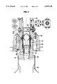
- FIG. 2 is a cross-sectional view of one embodiment showing the isolation sleeve separated from the extension sleeve.
- FIG. 3 is a perspective view of one embodiment of the invention.
- the apparatus has an isolation sleeve 10 and an extension sleeve 18.
- the isolation sleeve 10 has a first end 12, a second end 14 and a longitudinal axis 16 defined between the first end 12 and the second end 14.
- the sleeve 10 has a generally tubular shape.
- the extension sleeve 18 has a first end 20 attached to the second end 14 of the isolation sleeve 10 to form an assembly 21 comprising the isolation sleeve 10 and the extension sleeve 18, a second end 22, and a longitudinal axis 16 that is coaxially aligned with the longitudinal axis 16 of the isolation sleeve 10.
- FIG. 2 Like the isolation sleeve 10, the extension sleeve 18 has a generally tubular shape.
- the isolation sleeve 10 has an outer surface 24 defining an outer diameter and the extension sleeve 18 has an inside surface 26 defining an inner diameter.
- the inside surface 26 of the extension sleeve 18 is sized to closely receive the second end 14 of the isolation sleeve 10.
- the outer surface 24 of the isolation sleeve 10 near the second end 14 forms an annular wall portion 28 facing the second end 14.
- the inside surface 26 of the extension sleeve 18 forms a first annular shoulder portion 30 facing the first end 20 of the extension sleeve 18.
- the inside surface 26 of the extension sleeve 18 forms a second annular shoulder portion 34 facing the first end 20, where the second annular shoulder portion 34 is positioned between the first annular shoulder portion 30 and the second end 22 of the extension sleeve 18.
- the outer surface 24 of the isolation sleeve 10 defines threads 36 therein positioned between the annular wall portion 28 and the first end 12 for threadably engaging the threads on the extension sleeve, so that the assembly 21 is adjustable in length between the first end 12 of the isolation sleeve 10 and the second end 22 of the extension sleeve 18.
- a pair of set screws 11 are engaged to prevent the isolation sleeve from unthreading from the extension sleeve.
- the outer surface 24 of the isolation sleeve 10 includes a first seal means 38 near the second end 14 for sealably engaging the inside surface 26 of the extension sleeve 18.
- the first seal means 38 can be at least one annular groove 40 formed in the outer surface 24 of the isolation sleeve 10 and at least one elastomeric seal means 42 such as an O-ring positioned in the at least one annular groove 40.
- the outer surface 23 of the extension sleeve 18 includes a seal means 44 near the second end 22 for sealably engaging the inside surface of a casing hanger.
- the seal means 44 can be at least one annular groove 46 formed in the outer surface 23 of the extension sleeve 18 and at least one elastomeric seal means 48 positioned in the at least one annular groove 46.
- the outer surface 24 of the isolation sleeve 10 includes a second seal means 50 near the first end 12 for sealably engaging a spool body.
- the second seal means 50 can be at least one annular groove 52 formed in the outer surface 24 of the isolation sleeve 10 and at least one elastomeric seal means 54 positioned in the at least one annular groove 52.
- annular wall portion 28 of the isolation sleeve 10 abuts the first annular shoulder 30 of the extension sleeve 18 when the extension sleeve 18 is in a fully retracted position.
- the annular wall portion 28 on the isolation sleeve 10 can be in a spaced apart relationship with the first annular shoulder when the isolation sleeve 10 is in a second position.
- the isolation sleeve 10 is mounted onto the inside surface 26 of the spool body with a split lock ring 56, and a retainer ring 58.
- the retainer ring 58 slides in an upward direction and drives the lock ring 56 into an engaged position.
- a spool body 60 having an upper end 62, a lower end 64, an inside surface 66 defining a vertical bore 68 extending therethrough, and a longitudinal axis 70 extending between the upper end 62 and the lower end 64.
- the first end 12 of the isolation sleeve 10 is positioned within the vertical bore defined by the spool body 60 near the lower end, so that the outer surface 24 of the isolation sleeve 10 is sealingly engaged with the inside surface 66 defined by the spool body.
- the spool body 60 defines an annular shoulder 72 facing the lower end 64 of the spool body 60.
- the first end 12 of the isolation sleeve 10 forms an annular flange 74 having a face facing the first end 12, so that the annular shoulder 72 of the spool body 60 is closely received by the face 76 of the annular flange 74 when the isolation sleeve 10 is completely installed in the spool body 60.
- a wellhead 78 having an upper end 80, a lower end 82, and an inside surface 84 defining a vertical bore 86 extending therethrough.
- the lower end 64 of the spool body 60 is attached to the upper end 80 of the wellhead so that the second end 14 of the extension sleeve 18 extends down into the vertical bore defined by the wellhead.
- a casing hanger having an upper end, an outside surface, and an inside surface defining a vertical bore extending therethrough can also be provided. The inside surface of the casing hanger is sized to closely receive the outside surface of the extension sleeve 18 and the outside surface is attached to the inside surface of the wellhead.
Abstract
Description
Claims (12)
Priority Applications (1)
| Application Number | Priority Date | Filing Date | Title |
|---|---|---|---|
| US09/002,017 US6039120A (en) | 1997-12-31 | 1997-12-31 | Adjustable isolation sleeve |
Applications Claiming Priority (1)
| Application Number | Priority Date | Filing Date | Title |
|---|---|---|---|
| US09/002,017 US6039120A (en) | 1997-12-31 | 1997-12-31 | Adjustable isolation sleeve |
Publications (1)
| Publication Number | Publication Date |
|---|---|
| US6039120A true US6039120A (en) | 2000-03-21 |
Family
ID=21698876
Family Applications (1)
| Application Number | Title | Priority Date | Filing Date |
|---|---|---|---|
| US09/002,017 Expired - Lifetime US6039120A (en) | 1997-12-31 | 1997-12-31 | Adjustable isolation sleeve |
Country Status (1)
| Country | Link |
|---|---|
| US (1) | US6039120A (en) |
Cited By (25)
| Publication number | Priority date | Publication date | Assignee | Title |
|---|---|---|---|---|
| US6328108B1 (en) * | 1999-11-10 | 2001-12-11 | Cooper Cameron Corporation | Adjustable sub-tension hanger |
| US20030205385A1 (en) * | 2002-02-19 | 2003-11-06 | Duhn Rex E. | Connections for wellhead equipment |
| US20030221823A1 (en) * | 2002-02-19 | 2003-12-04 | Duhn Rex E. | Wellhead isolation tool |
| US20030226552A1 (en) * | 2002-03-15 | 2003-12-11 | Filterwerk Mann & Hummel Gmbh | Exhaust gas recycle (EGR) assembly |
| US6666266B2 (en) | 2002-05-03 | 2003-12-23 | Halliburton Energy Services, Inc. | Screw-driven wellhead isolation tool |
| US20050092496A1 (en) * | 2002-02-19 | 2005-05-05 | Duhn Rex E. | Wellhead isolation tool and method of fracturing a well |
| US20060060349A1 (en) * | 2002-02-19 | 2006-03-23 | Duhn Rex E | Wellhead isolation tool and method of fracturing a well |
| US20060185841A1 (en) * | 2005-02-18 | 2006-08-24 | Fmc Technologies, Inc. | Fracturing isolation sleeve |
| US20070023189A1 (en) * | 2005-07-27 | 2007-02-01 | Kahn Jon B | Tubing hanger connection |
| US20070261846A1 (en) * | 2001-07-30 | 2007-11-15 | Mackay Alexander C | Completion apparatus and methods for use in wellbores |
| US20080083539A1 (en) * | 2006-10-06 | 2008-04-10 | Stinger Wellhead Protection, Inc. | Retrievable frac mandrel and well control stack to facilitate well completion, re-completion or workover and method of use |
| US20080245529A1 (en) * | 2007-04-05 | 2008-10-09 | Vetco Gray Inc. | Through-Riser Installation of Tree Block |
| US20080277120A1 (en) * | 2007-05-11 | 2008-11-13 | Stinger Wellhead Protection, Inc. | Retrievable frac mandrel and well control stack to facilitate well completion, re-completion or workover and method of use |
| US20110031746A1 (en) * | 2009-04-06 | 2011-02-10 | Wayne Spears | Rotatable fire sprinkler fitting with elongated gasket |
| US20120111573A1 (en) * | 2010-11-08 | 2012-05-10 | Cameron International Corporation | Gasket test protector sleeve for subsea mineral extraction equipment |
| US20130175055A1 (en) * | 2012-01-06 | 2013-07-11 | Cameron International Corporation | Sealing Mechanism for Subsea Capping System |
| WO2014015050A3 (en) * | 2012-07-17 | 2014-04-10 | Ge Oil & Gas Pressure Control Lp | Adjustable isolation sleeve assembly for well stimulation through production tubing |
| WO2014133889A1 (en) * | 2013-02-26 | 2014-09-04 | Ge Oil & Gas Pressure Control Lp | Wellhead system for tieback retrieval |
| CN104695891A (en) * | 2015-03-04 | 2015-06-10 | 江炎芬 | Concentricity-adjustable variable-diameter sealer |
| WO2016069302A1 (en) * | 2014-10-30 | 2016-05-06 | Cameron International Corporation | Adjustable isolation sleeve |
| NO20170625A1 (en) * | 2017-04-12 | 2018-10-15 | Aker Solutions As | A wellhead arrangement |
| US20190113148A1 (en) * | 2017-10-17 | 2019-04-18 | Sun Hydraulics, Llc | Actuator Assembly and Method of Securing an Actuator to a Valve Body |
| US20190169983A1 (en) * | 2017-12-06 | 2019-06-06 | Onesubsea Ip Uk Limited | Subsea isolation sleeve system |
| US10744527B2 (en) | 2016-08-23 | 2020-08-18 | Viking Group, Inc. | Low torque sprinkler fitting and method of manufacture |
| US11872425B2 (en) | 2021-02-17 | 2024-01-16 | Minimax Viking Research & Development Gmbh | Fire protection systems and methods using fire protection devices installed in pipe fittings with an internally housed seal member |
Citations (13)
| Publication number | Priority date | Publication date | Assignee | Title |
|---|---|---|---|---|
| US3739846A (en) * | 1972-01-19 | 1973-06-19 | Rockwell Mfg Co | Head to hanger hydraulic connection |
| US3870101A (en) * | 1973-04-25 | 1975-03-11 | Baker Oil Tools Inc | Removable subsea production test valve assembly |
| US3965977A (en) * | 1973-04-19 | 1976-06-29 | Mcevoy Oilfield Equipment Co. | Control line exiting coupling |
| US3971576A (en) * | 1971-01-04 | 1976-07-27 | Mcevoy Oilfield Equipment Co. | Underwater well completion method and apparatus |
| GB2097885A (en) * | 1981-05-01 | 1982-11-10 | Nl Industries Inc | Wellhead connector with check valve |
| GB2132728A (en) * | 1981-05-01 | 1984-07-11 | Nl Industries Inc | Wellhead connector with check valve |
| GB2184508A (en) * | 1985-12-04 | 1987-06-24 | Vetco Offshore Ind Inc | Subsea safety check valve system |
| US4709725A (en) * | 1987-02-17 | 1987-12-01 | Vetco Gray, Inc. | Metal-to-metal seal structure |
| GB2195158A (en) * | 1986-09-16 | 1988-03-30 | Nat Oilwell | Wellhead connector |
| US4796922A (en) * | 1987-12-30 | 1989-01-10 | Vetco Gray Inc. | Subsea multiway hydraulic connector |
| US4898201A (en) * | 1989-02-09 | 1990-02-06 | Keystone International, Inc. | Portabl tool for cleaning valve bores and associated inlet passage |
| US5003821A (en) * | 1988-03-16 | 1991-04-02 | Rivero Olmedo Jose M | Meter box or meter yoke expansion mechanism |
| US5687999A (en) * | 1995-10-03 | 1997-11-18 | Vallourec Oil & Gas | Threaded joint for tubes |
-
1997
- 1997-12-31 US US09/002,017 patent/US6039120A/en not_active Expired - Lifetime
Patent Citations (15)
| Publication number | Priority date | Publication date | Assignee | Title |
|---|---|---|---|---|
| US3971576A (en) * | 1971-01-04 | 1976-07-27 | Mcevoy Oilfield Equipment Co. | Underwater well completion method and apparatus |
| US3739846A (en) * | 1972-01-19 | 1973-06-19 | Rockwell Mfg Co | Head to hanger hydraulic connection |
| US3965977A (en) * | 1973-04-19 | 1976-06-29 | Mcevoy Oilfield Equipment Co. | Control line exiting coupling |
| US3870101A (en) * | 1973-04-25 | 1975-03-11 | Baker Oil Tools Inc | Removable subsea production test valve assembly |
| GB2097885A (en) * | 1981-05-01 | 1982-11-10 | Nl Industries Inc | Wellhead connector with check valve |
| GB2132728A (en) * | 1981-05-01 | 1984-07-11 | Nl Industries Inc | Wellhead connector with check valve |
| GB2184508A (en) * | 1985-12-04 | 1987-06-24 | Vetco Offshore Ind Inc | Subsea safety check valve system |
| US4703774A (en) * | 1985-12-04 | 1987-11-03 | Vetco Gray Inc. | Subsea safety check valve system |
| GB2195158A (en) * | 1986-09-16 | 1988-03-30 | Nat Oilwell | Wellhead connector |
| US4852611A (en) * | 1986-09-16 | 1989-08-01 | National Oil Well (U.K.) Limited | Wellhead connection of hydraulic control lines |
| US4709725A (en) * | 1987-02-17 | 1987-12-01 | Vetco Gray, Inc. | Metal-to-metal seal structure |
| US4796922A (en) * | 1987-12-30 | 1989-01-10 | Vetco Gray Inc. | Subsea multiway hydraulic connector |
| US5003821A (en) * | 1988-03-16 | 1991-04-02 | Rivero Olmedo Jose M | Meter box or meter yoke expansion mechanism |
| US4898201A (en) * | 1989-02-09 | 1990-02-06 | Keystone International, Inc. | Portabl tool for cleaning valve bores and associated inlet passage |
| US5687999A (en) * | 1995-10-03 | 1997-11-18 | Vallourec Oil & Gas | Threaded joint for tubes |
Cited By (70)
| Publication number | Priority date | Publication date | Assignee | Title |
|---|---|---|---|---|
| US6328108B1 (en) * | 1999-11-10 | 2001-12-11 | Cooper Cameron Corporation | Adjustable sub-tension hanger |
| US20070261846A1 (en) * | 2001-07-30 | 2007-11-15 | Mackay Alexander C | Completion apparatus and methods for use in wellbores |
| US7481272B2 (en) * | 2001-07-30 | 2009-01-27 | Weatherford/Lamb, Inc. | Completion apparatus and methods for use in wellbores |
| US20080093067A1 (en) * | 2002-02-19 | 2008-04-24 | Duhn Oil Tool, Inc. | Wellhead isolation tool and method of fracturing a well |
| US20070272402A1 (en) * | 2002-02-19 | 2007-11-29 | Duhn Rex E | Wellhead isolation tool, wellhead assembly incorporating the same, and method of fracturing a well |
| US7416020B2 (en) | 2002-02-19 | 2008-08-26 | Duhn Oil Tool, Inc. | Wellhead isolation tool, wellhead assembly incorporating the same, and method of fracturing a well |
| US20050092496A1 (en) * | 2002-02-19 | 2005-05-05 | Duhn Rex E. | Wellhead isolation tool and method of fracturing a well |
| US6920925B2 (en) | 2002-02-19 | 2005-07-26 | Duhn Oil Tool, Inc. | Wellhead isolation tool |
| US20060060349A1 (en) * | 2002-02-19 | 2006-03-23 | Duhn Rex E | Wellhead isolation tool and method of fracturing a well |
| US8272433B2 (en) | 2002-02-19 | 2012-09-25 | Seaboard International Inc. | Wellhead isolation tool and wellhead assembly incorporating the same |
| US20100193178A1 (en) * | 2002-02-19 | 2010-08-05 | Duhn Rex E | Wellhead isolation tool and wellhead assembly incorporating the same |
| US20030205385A1 (en) * | 2002-02-19 | 2003-11-06 | Duhn Rex E. | Connections for wellhead equipment |
| US7493944B2 (en) | 2002-02-19 | 2009-02-24 | Duhn Oil Tool, Inc. | Wellhead isolation tool and method of fracturing a well |
| US7726393B2 (en) | 2002-02-19 | 2010-06-01 | Duhn Oil Tool, Inc. | Wellhead isolation tool and wellhead assembly incorporating the same |
| US7322407B2 (en) | 2002-02-19 | 2008-01-29 | Duhn Oil Tool, Inc. | Wellhead isolation tool and method of fracturing a well |
| US7520322B2 (en) | 2002-02-19 | 2009-04-21 | Duhn Oil Tool, Inc. | Wellhead isolation tool and method of fracturing a well |
| US20030221823A1 (en) * | 2002-02-19 | 2003-12-04 | Duhn Rex E. | Wellhead isolation tool |
| US8333237B2 (en) | 2002-02-19 | 2012-12-18 | Seaboard International Inc. | Wellhead isolation tool and wellhead assembly incorporating the same |
| US8863829B2 (en) | 2002-02-19 | 2014-10-21 | Seaboard International Inc. | Wellhead isolation tool and wellhead assembly incorporating the same |
| US6810865B2 (en) * | 2002-03-15 | 2004-11-02 | Mann & Hummel Gmbh | Exhaust gas recycle (EGR) assembly |
| US20030226552A1 (en) * | 2002-03-15 | 2003-12-11 | Filterwerk Mann & Hummel Gmbh | Exhaust gas recycle (EGR) assembly |
| US6666266B2 (en) | 2002-05-03 | 2003-12-23 | Halliburton Energy Services, Inc. | Screw-driven wellhead isolation tool |
| US20110155367A1 (en) * | 2005-02-18 | 2011-06-30 | Fmc Technologies, Inc. | Fracturing isolation sleeve |
| US7490666B2 (en) | 2005-02-18 | 2009-02-17 | Fmc Technologies, Inc. | Fracturing isolation sleeve |
| US20090178798A1 (en) * | 2005-02-18 | 2009-07-16 | Fmc Technologies, Inc. | Fracturing isolation sleeve |
| US7614448B2 (en) | 2005-02-18 | 2009-11-10 | Fmc Technologies, Inc. | Fracturing isolation sleeve |
| US7308934B2 (en) | 2005-02-18 | 2007-12-18 | Fmc Technologies, Inc. | Fracturing isolation sleeve |
| US8302678B2 (en) | 2005-02-18 | 2012-11-06 | Fmc Technologies Inc. | Fracturing isolation sleeve |
| US20060185841A1 (en) * | 2005-02-18 | 2006-08-24 | Fmc Technologies, Inc. | Fracturing isolation sleeve |
| US7900697B2 (en) | 2005-02-18 | 2011-03-08 | Fmc Technologies, Inc. | Fracturing isolation sleeve |
| US20080190601A1 (en) * | 2005-02-18 | 2008-08-14 | Fmc Technologies, Inc. | Fracturing isolation sleeve |
| US20070023189A1 (en) * | 2005-07-27 | 2007-02-01 | Kahn Jon B | Tubing hanger connection |
| US20080083539A1 (en) * | 2006-10-06 | 2008-04-10 | Stinger Wellhead Protection, Inc. | Retrievable frac mandrel and well control stack to facilitate well completion, re-completion or workover and method of use |
| US7775288B2 (en) | 2006-10-06 | 2010-08-17 | Stinger Wellhead Protection, Inc. | Retrievable frac mandrel and well control stack to facilitate well completion, re-completion or workover and method of use |
| US8011436B2 (en) * | 2007-04-05 | 2011-09-06 | Vetco Gray Inc. | Through riser installation of tree block |
| US20080245529A1 (en) * | 2007-04-05 | 2008-10-09 | Vetco Gray Inc. | Through-Riser Installation of Tree Block |
| US7806175B2 (en) | 2007-05-11 | 2010-10-05 | Stinger Wellhead Protection, Inc. | Retrivevable frac mandrel and well control stack to facilitate well completion, re-completion or workover and method of use |
| US20080277120A1 (en) * | 2007-05-11 | 2008-11-13 | Stinger Wellhead Protection, Inc. | Retrievable frac mandrel and well control stack to facilitate well completion, re-completion or workover and method of use |
| US20110031746A1 (en) * | 2009-04-06 | 2011-02-10 | Wayne Spears | Rotatable fire sprinkler fitting with elongated gasket |
| US8297663B2 (en) * | 2009-04-06 | 2012-10-30 | Spears Manufacturing Co. | Rotatable fire sprinkler fitting with elongated gasket |
| US20120111573A1 (en) * | 2010-11-08 | 2012-05-10 | Cameron International Corporation | Gasket test protector sleeve for subsea mineral extraction equipment |
| US8727012B2 (en) * | 2010-11-08 | 2014-05-20 | Cameron International Corporation | Gasket test protector sleeve for subsea mineral extraction equipment |
| US20130175055A1 (en) * | 2012-01-06 | 2013-07-11 | Cameron International Corporation | Sealing Mechanism for Subsea Capping System |
| US9382771B2 (en) * | 2012-01-06 | 2016-07-05 | Onesubsea Ip Uk Limited | Sealing mechanism for subsea capping system |
| GB2521281B (en) * | 2012-07-17 | 2019-10-09 | Ge Oil & Gas Pressure Control Lp | Adjustable isolation sleeve assembly for well stimulation through production tubing |
| CN105143595B (en) * | 2012-07-17 | 2018-02-23 | 通用电气石油和天然气压力控制有限公司 | For the adjustable distance sleeve component encouraged by the well of production pipeline |
| GB2521281A (en) * | 2012-07-17 | 2015-06-17 | Ge Oil & Gas Pressure Control Lp | Adjustable isolation sleeve assembly for well stimulation through production tubing |
| CN105143595A (en) * | 2012-07-17 | 2015-12-09 | 通用电气石油和天然气压力控制有限公司 | Adjustable isolation sleeve assembly for well stimulation through production tubing |
| WO2014015050A3 (en) * | 2012-07-17 | 2014-04-10 | Ge Oil & Gas Pressure Control Lp | Adjustable isolation sleeve assembly for well stimulation through production tubing |
| US9447671B2 (en) | 2012-07-17 | 2016-09-20 | Ge Oil & Gas Pressure Control Lp | Adjustable isolation sleeve assembly for well stimulation through production tubing |
| AU2013292670B2 (en) * | 2012-07-17 | 2017-02-16 | Vault Pressure Control Llc | Adjustable isolation sleeve assembly for well stimulation through production tubing |
| WO2014133889A1 (en) * | 2013-02-26 | 2014-09-04 | Ge Oil & Gas Pressure Control Lp | Wellhead system for tieback retrieval |
| US10364635B2 (en) | 2014-10-30 | 2019-07-30 | Cameron International Corporation | Adjustable isolation sleeve |
| WO2016069302A1 (en) * | 2014-10-30 | 2016-05-06 | Cameron International Corporation | Adjustable isolation sleeve |
| CN104695891A (en) * | 2015-03-04 | 2015-06-10 | 江炎芬 | Concentricity-adjustable variable-diameter sealer |
| US10744527B2 (en) | 2016-08-23 | 2020-08-18 | Viking Group, Inc. | Low torque sprinkler fitting and method of manufacture |
| CN110520594A (en) * | 2017-04-12 | 2019-11-29 | 阿克解决方案公司 | Well head arragement construction and method |
| RU2763284C2 (en) * | 2017-04-12 | 2021-12-28 | Акер Сольюшнз Ас | Device and method for arrangement of wellhead zone |
| US11761291B2 (en) * | 2017-04-12 | 2023-09-19 | Aker Solutions As | Wellhead arrangement and method |
| GB2576276B (en) * | 2017-04-12 | 2022-06-15 | Aker Solutions As | A wellhead arrangement and method |
| NO344391B1 (en) * | 2017-04-12 | 2019-11-25 | Aker Solutions As | A wellhead arrangement and installation method |
| NO20170625A1 (en) * | 2017-04-12 | 2018-10-15 | Aker Solutions As | A wellhead arrangement |
| GB2576276A (en) * | 2017-04-12 | 2020-02-12 | Aker Solutions As | A wellhead arrangement and method |
| WO2018190727A1 (en) | 2017-04-12 | 2018-10-18 | Aker Solutions As | A wellhead arrangement and method |
| US10781937B2 (en) * | 2017-10-17 | 2020-09-22 | Sun Hydraulics, Llc | Actuator assembly and method of securing an actuator to a valve body |
| US20190113148A1 (en) * | 2017-10-17 | 2019-04-18 | Sun Hydraulics, Llc | Actuator Assembly and Method of Securing an Actuator to a Valve Body |
| US10633966B2 (en) | 2017-12-06 | 2020-04-28 | Onesubsea Ip Uk Limited | Subsea isolation sleeve system |
| US20190169983A1 (en) * | 2017-12-06 | 2019-06-06 | Onesubsea Ip Uk Limited | Subsea isolation sleeve system |
| EP3495604A3 (en) * | 2017-12-06 | 2019-08-14 | OneSubsea IP UK Limited | Subsea isolation sleeve system |
| US11872425B2 (en) | 2021-02-17 | 2024-01-16 | Minimax Viking Research & Development Gmbh | Fire protection systems and methods using fire protection devices installed in pipe fittings with an internally housed seal member |
Similar Documents
| Publication | Publication Date | Title |
|---|---|---|
| US6039120A (en) | Adjustable isolation sleeve | |
| US5555935A (en) | Fluid connector for well | |
| US6360822B1 (en) | Casing annulus monitoring apparatus and method | |
| US7520322B2 (en) | Wellhead isolation tool and method of fracturing a well | |
| US7040410B2 (en) | Adapters for double-locking casing mandrel and method of using same | |
| USRE44520E1 (en) | Tubing hanger with annulus bore | |
| US6942028B2 (en) | Slim-bore tubing hanger | |
| US6557629B2 (en) | Wellhead isolation tool | |
| CA2172097C (en) | Dual string assembly for gas wells | |
| US6470971B1 (en) | Tubing head control and pressure monitor device | |
| US6920925B2 (en) | Wellhead isolation tool | |
| US20050121199A1 (en) | Casing hanger annulus monitoring system | |
| US4449583A (en) | Well devices with annulus check valve and hydraulic by-pass | |
| US20030205385A1 (en) | Connections for wellhead equipment | |
| US5605194A (en) | Independent screwed wellhead with high pressure capability and method | |
| US5450905A (en) | Pressure assist installation of production components in wellhead | |
| WO2003001025A1 (en) | Subsea wellhead equipment | |
| US7243733B2 (en) | Cup tool for a high-pressure mandrel and method of using same | |
| US7493944B2 (en) | Wellhead isolation tool and method of fracturing a well | |
| US3806168A (en) | Control line installation for down-hole safety valves | |
| US5341885A (en) | Internal tubing hanger lockdown | |
| US3299958A (en) | Unitized well head | |
| US5755290A (en) | Double swab barrier and method for producing and wireline intervening in a production tree | |
| CA2482335C (en) | Wellhead isolation tool and method of fracturing a well |
Legal Events
| Date | Code | Title | Description |
|---|---|---|---|
| AS | Assignment |
Owner name: KVAERNER OILFIELD PRODUCTS, TEXAS Free format text: ASSIGNMENT OF ASSIGNORS INTEREST;ASSIGNORS:MOLES, PETER;WILKINS, ROBERT LEE;REEL/FRAME:008926/0874 Effective date: 19971230 |
|
| FEPP | Fee payment procedure |
Free format text: PAYOR NUMBER ASSIGNED (ORIGINAL EVENT CODE: ASPN); ENTITY STATUS OF PATENT OWNER: LARGE ENTITY |
|
| STCF | Information on status: patent grant |
Free format text: PATENTED CASE |
|
| FEPP | Fee payment procedure |
Free format text: PAYOR NUMBER ASSIGNED (ORIGINAL EVENT CODE: ASPN); ENTITY STATUS OF PATENT OWNER: LARGE ENTITY Free format text: PAYER NUMBER DE-ASSIGNED (ORIGINAL EVENT CODE: RMPN); ENTITY STATUS OF PATENT OWNER: LARGE ENTITY |
|
| FPAY | Fee payment |
Year of fee payment: 4 |
|
| FEPP | Fee payment procedure |
Free format text: PAYOR NUMBER ASSIGNED (ORIGINAL EVENT CODE: ASPN); ENTITY STATUS OF PATENT OWNER: LARGE ENTITY Free format text: PAYER NUMBER DE-ASSIGNED (ORIGINAL EVENT CODE: RMPN); ENTITY STATUS OF PATENT OWNER: LARGE ENTITY |
|
| FPAY | Fee payment |
Year of fee payment: 8 |
|
| FPAY | Fee payment |
Year of fee payment: 12 |
|
| AS | Assignment |
Owner name: AKER SOLUTIONS INC, TEXAS Free format text: CHANGE OF NAME;ASSIGNORS:KVAERNER OILFIELD PRODUCTS;AKER KVAERNER SUBSEA INC;AKER SUBSEA INC;SIGNING DATES FROM 20050509 TO 20120802;REEL/FRAME:041884/0307 |