US6049940A - Control circuit for a liquid collecting device - Google Patents
Control circuit for a liquid collecting device Download PDFInfo
- Publication number
- US6049940A US6049940A US09/285,211 US28521199A US6049940A US 6049940 A US6049940 A US 6049940A US 28521199 A US28521199 A US 28521199A US 6049940 A US6049940 A US 6049940A
- Authority
- US
- United States
- Prior art keywords
- liquid
- tank
- pump
- motor
- actuator
- Prior art date
- Legal status (The legal status is an assumption and is not a legal conclusion. Google has not performed a legal analysis and makes no representation as to the accuracy of the status listed.)
- Expired - Lifetime
Links
Images


Classifications
-
- A—HUMAN NECESSITIES
- A47—FURNITURE; DOMESTIC ARTICLES OR APPLIANCES; COFFEE MILLS; SPICE MILLS; SUCTION CLEANERS IN GENERAL
- A47L—DOMESTIC WASHING OR CLEANING; SUCTION CLEANERS IN GENERAL
- A47L7/00—Suction cleaners adapted for additional purposes; Tables with suction openings for cleaning purposes; Containers for cleaning articles by suction; Suction cleaners adapted to cleaning of brushes; Suction cleaners adapted to taking-up liquids
- A47L7/0004—Suction cleaners adapted to take up liquids, e.g. wet or dry vacuum cleaners
- A47L7/0042—Gaskets; Sealing means
-
- A—HUMAN NECESSITIES
- A47—FURNITURE; DOMESTIC ARTICLES OR APPLIANCES; COFFEE MILLS; SPICE MILLS; SUCTION CLEANERS IN GENERAL
- A47L—DOMESTIC WASHING OR CLEANING; SUCTION CLEANERS IN GENERAL
- A47L11/00—Machines for cleaning floors, carpets, furniture, walls, or wall coverings
- A47L11/29—Floor-scrubbing machines characterised by means for taking-up dirty liquid
- A47L11/30—Floor-scrubbing machines characterised by means for taking-up dirty liquid by suction
-
- A—HUMAN NECESSITIES
- A47—FURNITURE; DOMESTIC ARTICLES OR APPLIANCES; COFFEE MILLS; SPICE MILLS; SUCTION CLEANERS IN GENERAL
- A47L—DOMESTIC WASHING OR CLEANING; SUCTION CLEANERS IN GENERAL
- A47L11/00—Machines for cleaning floors, carpets, furniture, walls, or wall coverings
- A47L11/40—Parts or details of machines not provided for in groups A47L11/02 - A47L11/38, or not restricted to one of these groups, e.g. handles, arrangements of switches, skirts, buffers, levers
- A47L11/4011—Regulation of the cleaning machine by electric means; Control systems and remote control systems therefor
-
- A—HUMAN NECESSITIES
- A47—FURNITURE; DOMESTIC ARTICLES OR APPLIANCES; COFFEE MILLS; SPICE MILLS; SUCTION CLEANERS IN GENERAL
- A47L—DOMESTIC WASHING OR CLEANING; SUCTION CLEANERS IN GENERAL
- A47L11/00—Machines for cleaning floors, carpets, furniture, walls, or wall coverings
- A47L11/40—Parts or details of machines not provided for in groups A47L11/02 - A47L11/38, or not restricted to one of these groups, e.g. handles, arrangements of switches, skirts, buffers, levers
- A47L11/4013—Contaminants collecting devices, i.e. hoppers, tanks or the like
- A47L11/4016—Contaminants collecting devices, i.e. hoppers, tanks or the like specially adapted for collecting fluids
- A47L11/4019—Fill level sensors; Security means to prevent overflow, e.g. float valves
-
- A—HUMAN NECESSITIES
- A47—FURNITURE; DOMESTIC ARTICLES OR APPLIANCES; COFFEE MILLS; SPICE MILLS; SUCTION CLEANERS IN GENERAL
- A47L—DOMESTIC WASHING OR CLEANING; SUCTION CLEANERS IN GENERAL
- A47L11/00—Machines for cleaning floors, carpets, furniture, walls, or wall coverings
- A47L11/40—Parts or details of machines not provided for in groups A47L11/02 - A47L11/38, or not restricted to one of these groups, e.g. handles, arrangements of switches, skirts, buffers, levers
- A47L11/4013—Contaminants collecting devices, i.e. hoppers, tanks or the like
- A47L11/4025—Means for emptying
-
- A—HUMAN NECESSITIES
- A47—FURNITURE; DOMESTIC ARTICLES OR APPLIANCES; COFFEE MILLS; SPICE MILLS; SUCTION CLEANERS IN GENERAL
- A47L—DOMESTIC WASHING OR CLEANING; SUCTION CLEANERS IN GENERAL
- A47L11/00—Machines for cleaning floors, carpets, furniture, walls, or wall coverings
- A47L11/40—Parts or details of machines not provided for in groups A47L11/02 - A47L11/38, or not restricted to one of these groups, e.g. handles, arrangements of switches, skirts, buffers, levers
- A47L11/4027—Filtering or separating contaminants or debris
-
- A—HUMAN NECESSITIES
- A47—FURNITURE; DOMESTIC ARTICLES OR APPLIANCES; COFFEE MILLS; SPICE MILLS; SUCTION CLEANERS IN GENERAL
- A47L—DOMESTIC WASHING OR CLEANING; SUCTION CLEANERS IN GENERAL
- A47L11/00—Machines for cleaning floors, carpets, furniture, walls, or wall coverings
- A47L11/40—Parts or details of machines not provided for in groups A47L11/02 - A47L11/38, or not restricted to one of these groups, e.g. handles, arrangements of switches, skirts, buffers, levers
- A47L11/4036—Parts or details of the surface treating tools
- A47L11/4044—Vacuuming or pick-up tools; Squeegees
-
- A—HUMAN NECESSITIES
- A47—FURNITURE; DOMESTIC ARTICLES OR APPLIANCES; COFFEE MILLS; SPICE MILLS; SUCTION CLEANERS IN GENERAL
- A47L—DOMESTIC WASHING OR CLEANING; SUCTION CLEANERS IN GENERAL
- A47L11/00—Machines for cleaning floors, carpets, furniture, walls, or wall coverings
- A47L11/40—Parts or details of machines not provided for in groups A47L11/02 - A47L11/38, or not restricted to one of these groups, e.g. handles, arrangements of switches, skirts, buffers, levers
- A47L11/4072—Arrangement of castors or wheels
-
- A—HUMAN NECESSITIES
- A47—FURNITURE; DOMESTIC ARTICLES OR APPLIANCES; COFFEE MILLS; SPICE MILLS; SUCTION CLEANERS IN GENERAL
- A47L—DOMESTIC WASHING OR CLEANING; SUCTION CLEANERS IN GENERAL
- A47L11/00—Machines for cleaning floors, carpets, furniture, walls, or wall coverings
- A47L11/40—Parts or details of machines not provided for in groups A47L11/02 - A47L11/38, or not restricted to one of these groups, e.g. handles, arrangements of switches, skirts, buffers, levers
- A47L11/4077—Skirts or splash guards
-
- A—HUMAN NECESSITIES
- A47—FURNITURE; DOMESTIC ARTICLES OR APPLIANCES; COFFEE MILLS; SPICE MILLS; SUCTION CLEANERS IN GENERAL
- A47L—DOMESTIC WASHING OR CLEANING; SUCTION CLEANERS IN GENERAL
- A47L7/00—Suction cleaners adapted for additional purposes; Tables with suction openings for cleaning purposes; Containers for cleaning articles by suction; Suction cleaners adapted to cleaning of brushes; Suction cleaners adapted to taking-up liquids
- A47L7/0004—Suction cleaners adapted to take up liquids, e.g. wet or dry vacuum cleaners
- A47L7/0023—Recovery tanks
- A47L7/0028—Security means, e.g. float valves or level switches for preventing overflow
-
- A—HUMAN NECESSITIES
- A47—FURNITURE; DOMESTIC ARTICLES OR APPLIANCES; COFFEE MILLS; SPICE MILLS; SUCTION CLEANERS IN GENERAL
- A47L—DOMESTIC WASHING OR CLEANING; SUCTION CLEANERS IN GENERAL
- A47L7/00—Suction cleaners adapted for additional purposes; Tables with suction openings for cleaning purposes; Containers for cleaning articles by suction; Suction cleaners adapted to cleaning of brushes; Suction cleaners adapted to taking-up liquids
- A47L7/0004—Suction cleaners adapted to take up liquids, e.g. wet or dry vacuum cleaners
- A47L7/0023—Recovery tanks
- A47L7/0038—Recovery tanks with means for emptying the tanks
-
- A—HUMAN NECESSITIES
- A61—MEDICAL OR VETERINARY SCIENCE; HYGIENE
- A61L—METHODS OR APPARATUS FOR STERILISING MATERIALS OR OBJECTS IN GENERAL; DISINFECTION, STERILISATION OR DEODORISATION OF AIR; CHEMICAL ASPECTS OF BANDAGES, DRESSINGS, ABSORBENT PADS OR SURGICAL ARTICLES; MATERIALS FOR BANDAGES, DRESSINGS, ABSORBENT PADS OR SURGICAL ARTICLES
- A61L2/00—Methods or apparatus for disinfecting or sterilising materials or objects other than foodstuffs or contact lenses; Accessories therefor
- A61L2/02—Methods or apparatus for disinfecting or sterilising materials or objects other than foodstuffs or contact lenses; Accessories therefor using physical phenomena
- A61L2/14—Plasma, i.e. ionised gases
-
- A—HUMAN NECESSITIES
- A61—MEDICAL OR VETERINARY SCIENCE; HYGIENE
- A61L—METHODS OR APPARATUS FOR STERILISING MATERIALS OR OBJECTS IN GENERAL; DISINFECTION, STERILISATION OR DEODORISATION OF AIR; CHEMICAL ASPECTS OF BANDAGES, DRESSINGS, ABSORBENT PADS OR SURGICAL ARTICLES; MATERIALS FOR BANDAGES, DRESSINGS, ABSORBENT PADS OR SURGICAL ARTICLES
- A61L2/00—Methods or apparatus for disinfecting or sterilising materials or objects other than foodstuffs or contact lenses; Accessories therefor
- A61L2/16—Methods or apparatus for disinfecting or sterilising materials or objects other than foodstuffs or contact lenses; Accessories therefor using chemical substances
- A61L2/20—Gaseous substances, e.g. vapours
-
- F—MECHANICAL ENGINEERING; LIGHTING; HEATING; WEAPONS; BLASTING
- F16—ENGINEERING ELEMENTS AND UNITS; GENERAL MEASURES FOR PRODUCING AND MAINTAINING EFFECTIVE FUNCTIONING OF MACHINES OR INSTALLATIONS; THERMAL INSULATION IN GENERAL
- F16K—VALVES; TAPS; COCKS; ACTUATING-FLOATS; DEVICES FOR VENTING OR AERATING
- F16K1/00—Lift valves or globe valves, i.e. cut-off apparatus with closure members having at least a component of their opening and closing motion perpendicular to the closing faces
- F16K1/32—Details
- F16K1/52—Means for additional adjustment of the rate of flow
- F16K1/526—Means for additional adjustment of the rate of flow for limiting the maximum flow rate, using a second valve
-
- Y—GENERAL TAGGING OF NEW TECHNOLOGICAL DEVELOPMENTS; GENERAL TAGGING OF CROSS-SECTIONAL TECHNOLOGIES SPANNING OVER SEVERAL SECTIONS OF THE IPC; TECHNICAL SUBJECTS COVERED BY FORMER USPC CROSS-REFERENCE ART COLLECTIONS [XRACs] AND DIGESTS
- Y10—TECHNICAL SUBJECTS COVERED BY FORMER USPC
- Y10S—TECHNICAL SUBJECTS COVERED BY FORMER USPC CROSS-REFERENCE ART COLLECTIONS [XRACs] AND DIGESTS
- Y10S15/00—Brushing, scrubbing, and general cleaning
- Y10S15/10—Handles, reels and switches
-
- Y—GENERAL TAGGING OF NEW TECHNOLOGICAL DEVELOPMENTS; GENERAL TAGGING OF CROSS-SECTIONAL TECHNOLOGIES SPANNING OVER SEVERAL SECTIONS OF THE IPC; TECHNICAL SUBJECTS COVERED BY FORMER USPC CROSS-REFERENCE ART COLLECTIONS [XRACs] AND DIGESTS
- Y10—TECHNICAL SUBJECTS COVERED BY FORMER USPC
- Y10T—TECHNICAL SUBJECTS COVERED BY FORMER US CLASSIFICATION
- Y10T137/00—Fluid handling
- Y10T137/7287—Liquid level responsive or maintaining systems
- Y10T137/7306—Electrical characteristic sensing
Definitions
- the present invention relates to vacuum cleaners and more particularly to wet/dry vacuum cleaners where liquid material in the tank of the vacuum cleaner is pumped out to waste.
- Tank-type vacuum cleaners are capable of receiving dry materials such as debris or dirt and may also be used for suctioning liquids.
- an upper vacuum assembly which often includes a motor and an air impeller
- the vacuum cleaner is used on liquid material, the tank, when at or near capacity, may be very heavy so that lifting the tank, to pour the contents into a sink or the like, is difficult. Even tilting the tank to pour the contents into a floor drain may be unwieldy when the liquid level in the tank is high.
- a second solution to emptying a vacuum tank of liquid is to provide a pump, usually with a motor located outside of or in the bottom of the tank.
- the pump removes liquid through a lower portion of the tank and expels it through a hose to waste. While such pumps are generally effective, they may be very costly.
- the pump requires not only a pump impeller and hoses but also its own electric motor, power cords, and switches. The expense of such items may be significant in the context of the overall cost of a vacuum cleaner, particularly those designed for residential use.
- Such pumps may also reduce the effective capacity of the vacuum tank or interfere with operation when the vacuum cleaner is used on dry materials.
- a vacuum cleaner has a tank for collecting vacuumed materials and an air impeller for creating low pressure in the tank to draw material into the tank.
- a shaft extends from the air impeller and rotates with the air impeller.
- a pump impeller is mechanically connected to the air impeller by the shaft so that the pump impeller draws the vacuumed material out of the tank.
- the vacuum cleaner may have a motor driving the air impeller and the pump impeller.
- An upper vacuum assembly may carry the motor and the air impeller, and may also carry an upper pump assembly which includes the pump impeller.
- a lower pump assembly is removably attached to the upper pump assembly, and the lower pump assembly includes a pump inlet tube communicating with a lower portion of the tank.
- the vacuum cleaner may have a tank extension which is supported by the tank between the tank and the upper vacuum assembly. The tank extension is removable from the tank and the upper vacuum assembly, and carries the lower pump assembly.
- the lower pump assembly may have a fluid filter and means for sending a priming fluid toward the pump impeller.
- a pump for the vacuum cleaner including the pump impeller may have an inlet near a lower portion of the tank.
- An outlet is provided exterior to the tank so that material in the tank is drawn into the pump inlet by the pump impeller and expelled from the pump outlet.
- a bellows is connected to the pump inlet and has an opening to permit liquid in the tank to enter into the bellows. When the bellows are compressed, liquid is forced from the bellows toward the pump impeller.
- the bellows may be compressed by a handle connected to the bellows and located outside the tank.
- a wet/dry vacuum cleaner may have a tank for receiving vacuumed material and an upper vacuum assembly carrying a motor and an air impeller.
- a pump removes liquid material from the tank and includes an upper pump assembly having a pump impeller where the upper pump assembly is attached to the upper vacuum assembly.
- the pump also includes a lower pump assembly which is removably attached to the upper pump assembly.
- the lower pump assembly includes a pump inlet tube communicating with a lower portion of the tank.
- the vacuum cleaner may have a tank extension where an outlet for the pump passes through the tank extension.
- a priming handle may also pass through the lid extension.
- the upper pump assembly may include an impeller housing, and the lower pump assembly may include a pump outlet fitting.
- the pump outlet fitting contains an inlet tube having a seal, and the pump outlet fitting communicates with an outlet to the tank and has a pump outlet seal. The seal on the inlet tube and the seal on the pump outlet, each separate to separate the upper pump assembly from the lower pump assembly.
- a vacuum cleaner has a tank for collecting vacuumed material.
- An air impeller is driven by a source of mechanical force to create a low-pressure area in the tank to draw material into the tank.
- a pump is located in the tank and driven by the source of mechanical force.
- An inlet to the pump is near a lower portion of the tank and an outlet to the pump is exterior to the tank. Liquid material in the tank is drawn into the pump inlet by the pump impeller and expelled through the pump outlet.
- the air impeller may rotate about a first shaft, and the pump impeller may rotate about a second shaft.
- the first shaft may be essentially collinear with the second shaft.
- the second shaft may connect the air impeller to the pump impeller.
- the wet/dry vacuum cleaner may be controlled by a control circuit.
- the control circuit has an electrode disposed at a particular liquid level height in the liquid collection tank.
- the control circuit also has a means for enabling the liquid collection device when the liquid level in the liquid collection tank is below the particular liquid level height.
- a means is coupled to the enabling means for selectively bypassing the disabling means to re-enable the liquid collection device when the liquid level in the liquid collection tank reaches the particular liquid level height.
- the control circuit may also have an additional means coupled to the enabling means for disabling the liquid collection device after the liquid collection device has been re-enabled by the bypass means.
- a further electrode may be coupled to the additional disabling means and disposed at a further liquid level height in the liquid collection tank. The additional disabling means disables the liquid collection device when the liquid level in the liquid collection tank reaches the further liquid level height.
- the wet/dry vacuum cleaner may include a mechanical shut-off and bypass assembly.
- the mechanical shut-off and bypass assembly includes a switch having a first position in which power is provided to the motor and a second position in which power to the motor is interrupted, a user operated actuator mechanism mechanically linked to the switch and capable of moving the switch to the first position or the second position, and a float mechanically linked to the switch and capable of moving the switch from the first position to the second position.
- the wet/dry vacuum cleaner may include a toggle member capable of engaging the switch and capable of moving the switch to the first or second position.
- a float transmission rod may be disposed between the toggle member and the float, putting the float transmission rod in cooperation with the toggle member and the float.
- the toggle member of the mechanical shut-off and bypass assembly may include a locking brace having a ramp portion and a locking portion.
- the locking portion and the ramp portion intersect to form a critical point.
- the switch may include a depressible actuator, which is engageable by the locking brace and remains depressed by the locking portion once the critical point is rotated counter-clockwise past said depressible actuator.
- the mechanical shut-off and bypass assembly has a cover which defines an actuator slot and the actuator mechanism includes an upper leaf spring, a lower leaf spring, a leaf connection member spanning between and connecting the upper and lower leaf spring, and a toggle actuator disposed in the actuator slot and in cooperation with the leaf connection member, whereby the upper and lower leaf spring center the toggle actuator in the actuator slot of the cover.
- the actuator mechanism of the mechanical shut-off and bypass assembly may include a female connection port having an upper lip and a lower lip, and further defining a boss slot
- the toggle member may include a sidewall and a boss, the boss being connected to the sidewall and extending outward from the toggle member and into the boss slot, and the geometry of the boss slot is such that neither the upper nor lower lip of the female connection port engages the boss when the actuator mechanism is at rest.
- the mechanical shut-off and bypass assembly may be employed in other apparatus.
- the mechanical shut-off and bypass assembly is not limited to use in a wet/dry vacuum cleaner.
- FIG. 1 is a side elevational view of a vacuum cleaner of the present invention
- FIG. 2 is a diagrammatic view of a vacuum cleaner of the present invention
- FIG. 3 is a top plan view of a vacuum cleaner of the present invention.
- FIG. 4 is a side elevational view, partially in section along the line 4--4 in FIG. 3;
- FIG. 5 is a front elevational view, partially in section, along the line 5--5 in FIG. 3;
- FIG. 6 is a view similar to FIG. 5 showing the pump of the vacuum cleaner being primed
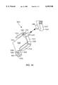
- FIG. 7 is a side elevational view of a vacuum cleaner of the present invention with a tank extension removed;
- FIG. 8 is a view similar to FIG. 5 of the vacuum cleaner of FIG. 7;
- FIG. 9 is a diagrammatic view of the vacuum cleaner of the present invention configured with electrode level sensors
- FIG. 10 is a schematic diagram of a preferred embodiment of a control circuit
- FIG. 11 is a top plan view of a vacuum cleaner of the present invention employing a preferred embodiment of a mechanical shut-off and bypass assembly;
- FIG. 12 is a view similar to FIG. 4 showing the preferred embodiment of the mechanical shut-off and bypass assembly
- FIG. 13 is a view similar to FIG. 5 showing the preferred embodiment of the mechanical shut-off and bypass system
- FIG. 14. is a perspective view of a linkage and a toggle actuator of an actuator mechanism
- FIG. 15 is a perspective view of the actuator mechanism, a toggle member, and a switch mounted in a switch mounting box;
- FIG. 16 is a front elevational view of the actuator mechanism, the toggle member, and the switch mounted in the switch mounting box and the switch mounting box attached to a motor housing;
- FIG. 17 is a perspective view of the toggle member
- FIG. 18 is a side elevational view of the toggle
- FIG. 19 is a sectional view of the toggle taken along the line 19--19 in FIG. 17;
- FIG. 20 is a partial view, partially in section, of the actuator mechanism, the toggle member, and the switch of the mechanical shut-off and bypass assembly in an "ON" position;
- FIG. 21 is a partial view, partially in section, of the actuator mechanism, the toggle member, and the switch transitioning from the "ON" to an "OFF" position;
- FIG. 22 is a partial view, partially in section, of the actuator mechanism, the toggle member, and the switch in the "OFF" position;
- FIG. 23 is a partial view, partially in section, of the actuator mechanism, the toggle member, and the switch transitioning from the "OFF" to the "ON” position;
- FIG. 24 is a front elevational view of the mechanical shut-off and bypass assembly in an "ON" position
- FIG. 25 is a side elevational view of the mechanical shut-off and bypass assembly in an "ON" position
- FIG. 26 is a side elevational view of the mechanical shut-off and bypass assembly transitioning to the "OFF" position due to an excessively high water level
- FIG. 27 is a side elevational view of the user bypassing the mechanical shut-off.
- a vacuum cleaner of the present invention has a tank 12 supported by casters 14.
- the tank 12 further includes a pair of handles 20 (FIGS. 1 and 3), an inlet 26, and an upper rim 13.
- the handles 20 may be used to assist the user in lifting and moving the vacuum cleaner 10.
- the inlet 26 may be fitted with a vacuum hose (not depicted) for applying suction at desired locations.
- the tank 12 supports a removable tank extension 28.
- the tank extension 28 engages the upper rim 13 of the tank 12 and is disposed within the tank 12.
- the tank extension 28, in turn, supports an upper vacuum assembly, indicated generally at 15.
- the upper vacuum assembly 15 includes a lid 16, a motor housing 18, a cover 19, and a handle 22.
- the lid 16 is disposed above the tank extension 28 and may be attached to the tank extension 28 by one or more latches 29 which are carried by the lid 16.
- the latches 29 fit into tank recesses 31 when the tank extension 28 is removed.
- the motor housing 18 is disposed above the lid 16 and is connected to the lid 16.
- the motor housing 18 defines a pair of blower air discharge slots 21 (FIGS. 1 and 3).
- the blower air discharge slots 21 are disposed along a lower portion 23 of the motor housing 18. Air drawn into the vacuum cleaner 10 by the inlet 26 is expelled through the blower air discharge slots 21 as shown by the arrow BA in FIG. 1.
- the cover 19 is disposed above the motor housing 18 and is connected to the motor housing 18.
- the motor housing 18 and the cover 19 may be formed as two separate, detachable pieces or as one piece, integral with one another.
- the cover 19 includes an electric cord attachment 25.
- the electric cord attachment 25 connects the cover 19 to an electric cord 24 which provides power to the vacuum cleaner 10.
- the motor housing 18 and the cover 19 further define a cooling air opening 27.
- the cooling air opening 27 allows air to enter and exit under the cover 19, as shown by the arrows CA in FIG. 1.
- the air entering and exiting under the cover 19 circulates downward and cools a motor (not depicted) disposed within the motor housing 18.
- the handle 22 is disposed above the cover 19 and is connected to the cover 19.
- FIG. 2 is a diagram showing the overall electrical and mechanical operation of the vacuum cleaner 10.
- a motor 34 drives an air impeller 36 via a shaft 38.
- the air impeller 36 draws air through an opening 35 in an air impeller housing 37 from the tank 12, which in turn draws air and other material through the inlet 26. Air may be expelled directly from the air impeller 36 through the upper vacuum assembly 15, or may pass through or over the motor 34 to provide cooling.
- a pump impeller 40 is driven by a shaft 42 which passes through the opening 35 in the air impeller housing 37.
- the shaft 38 may be integral with the shaft 42 so that a unitary structure drives both the air impeller 36 and the pump impeller 40.
- the shaft 42 may be separate from the shaft 38, in which case the shafts are preferably essentially collinear.
- the shaft 38 and the shaft 42 may not be collinear but may instead transfer torque from the motor 34 through the shaft 38 to the shaft 42 and pump impeller 40 via a transmission or gears.
- the pump impeller 40 is not self-priming. A user has to manually prime the pump impeller 40 in order to pump liquid material out of the tank 12. This feature provides a significant advantage to the user. With a manual priming system, the pump only operates when the user is ready to discharge the liquid material collected in the tank 12. In other words, with the present invention, the user can vacuum up liquid material in a first location lacking a drainage source; stop vacuuming; then, move the vacuum cleaner 10 to a second location having a drainage source; manually prime the pump impeller 40; and begin pumping out the liquid material collected in the tank 12.
- a bellows 50 may be compressed by use of the priming handle 32 and a priming rod 52.
- liquid material enters the tank 12 it collects in the bottom of the tank 12 and enters the bellows 50 through a pump inlet 44.
- a check valve 54 adjacent the pump inlet 44 permits liquid to enter the bellows 50 through the pump inlet 44 but resists flow of material from the bellows 50 out through the pump inlet 44.
- a level sensor 56 may therefore be provided to detect when the level of liquid in the tank 12 is at or above a specified level.
- the level sensor 56 detects liquid at or above the specified level it sends a signal to a switch 60.
- the switch 60 upon receiving the signal, interrupts current flowing through the electric cord 24 to the motor 34.
- the motor 34 and air impeller 36 thereby cease operating so that no additional liquid material enters the tank 12.
- a switch 62 with a depressible actuator 64 is therefore provided to allow a user to override the interruption in power caused by activation of the level sensor 56.
- the depressible actuator 64 is biased to the "OFF" position and must be maintained in the depressed position in order for the switch 62 to provide electric power to the motor 34. While the user depresses the depressible actuator 64, the user is aware that the tank 12 is full and that the user should avoid further suctioning of additional liquid material into the tank 12 through the inlet 26.
- the pump impeller 40 will also continue to operate. Continued operation of the pump impeller 40 will empty the tank to a level below the specified level for the level sensor 56 so that the switch 60 thereafter permits flow of electric power to the motor 34 without the need to depress the depressible actuator 64.
- a second level sensor (not depicted) may be placed at a level higher than the specified level which prevents the interruption in power from being overridden. Thus, if the user holds down the toggle while allowing additional liquid material to enter the tank 12, the second sensor will disable the motor 34 and prevent the tank 12 from overfilling.
- Numerous types of level sensors 56 may be used, including float sensors, proximity sensors, optical sensors, pairs of electrodes which pass current to each other through liquid in the tank when the liquid is at a sufficient height, etc.
- two level sensors could be provided (not depicted).
- the first, lower sensor activates a light or alarm to warn the user that the tank 12 is almost full.
- the user ceases suctioning additional material into the tank until the level of liquid material in the tank is lowered. If the user fails to heed the warning and the liquid level in the tank continues to rise, the second level sensor interrupts power to the motor 34.
- FIGS. 4 and 5 depict the internal structure of an embodiment of the vacuum cleaner 10.
- the motor (not depicted) drives two air impellers 36 mounted in an air impeller housing 37 via the first axle 38.
- the vacuum cleaner 10 may alternatively have only a single air impeller.
- the air impellers 36 draw air through a lid cage indicated generally at 61, which in turn draws air through a depending portion 63 of the tank extension 28.
- the depending portion 63 defines several holes or slots (not depicted) which permit air flow to the air impellers 36.
- the lid cage 61 has several braces 65 supporting a plate 66 and surrounded by a foam filter 67.
- the upper vacuum assembly 15, which carries the cage 61, impellers 36, and motor, may be of conventional construction. Except for the pump and shut-off switches discussed below, the upper vacuum assembly 15 and its associated components may be identical to a Shop Vac Model QL20TS vacuum cleaner as manufactured by Shop Vac Corporation of Williamsport, Pa.
- a pump indicated generally at 68 includes the pump impeller 40, which is mounted between an upper impeller housing 70 and a lower impeller housing 72.
- the lower impeller housing 72 includes an outer chamber wall 69 and an inner chamber wall 71, best seen in FIG. 8.
- the outer chamber wall 69 defines one portion of a discharge recess 73 and the inner chamber wall 71 defines an inner chamber 75.
- An inlet tube 74 is telescoped within the inner chamber 75.
- the inlet tube 74 includes a seal 76 which is disposed between the inlet tube 74 and the inner chamber wall 71.
- the seal 76 divides the inner chamber 75 into an upper priming chamber 77 and a lower chamber 79.
- the lower chamber 79 is in communication with the discharge recess 73.
- the inlet tube 74 is secured by any suitable means to the inlet tube 46.
- a pump outlet fitting 78 is telescoped within the housing 72.
- the pump outlet fitting 78 includes a seal 80 which is disposed between the pump outlet fitting 78 and the housing 72.
- the pump outlet fitting 78 defines the other portion of the discharge recess 73.
- the pump impeller 40 draws liquid through the inlet tubes 46 and 74 into the upper priming chamber 77, and finally into the discharge recess 73.
- the liquid in the discharge recess 73 surrounds the tubes 46 and 74.
- the liquid then passes from the discharge recess 73 through the pump outlet fitting 78, into an outlet tube 48, and out of the tank 12 through the pump outlet 30 (FIG. 5).
- the seal 80 prevents liquid from escaping past the interface between the housing 72 and the pump outlet fitting 78.
- the seal 76 When the discharge recess 73 is full with liquid, the seal 76 is surrounded by liquid. The liquid in the upper priming chamber 77 contacts a top surface 81 of the seal 76 and the liquid in the lower chamber 79 contacts a bottom surface 83 of the seal 76. Consequently, when the pump 68 is in operation, the seal 76 is surrounded by liquid on the top and bottom surfaces 81, 83. Surrounding the seal 76 with liquid is a significant advantage of the present invention. By surrounding the seal 76 with liquid, the pump 68 will not lose its prime.
- the lower impeller housing 72 is attached to the upper impeller housing 70, which is in turn attached to a pump mount 85.
- the pump mount 85 is attached to the air impeller housing 37.
- the pump mount 85 also carries a water deflector 87, which inhibits water from passing into the air impellers 36.
- Ordinary pumps have a seal where the shaft 42 passes through the upper impeller housing 70.
- the pump 68 has no such seal because seals often require cooling fluid and the pump impeller 40 may rotate without any fluid in the upper impeller housing 70. A small amount of liquid will therefore pass out of the upper impeller housing 70 around the shaft 42.
- the water deflector 87 will direct the liquid back into the tank 12.
- the pump outlet fitting 78 is mounted to an inverted cup 82 on the tank extension 28.
- the tank extension 28 carries an intake support 84 and a lower cage indicated generally at 86 having brackets 88 and a plate 90.
- the lower cage 86 may be surrounded by a foam filter 91 to prevent large particles suspended in liquid in the tank 12 from entering the pump inlet 44.
- the lower cage 86 also houses the priming mechanism for the pump 68, including the bellows 50, which is secured to the intake support 84 by a hose clamp 92 (FIG. 5). The lower end of the bellows 50 is captured between a bracket 94 and a cup 96.
- the bellows 50, bracket 94, and the cup 96 each have an opening to allow liquid material in the tank 12 to enter into the cup 96.
- a ball 97 seats in the cup 96 to form the check valve 54 which prevents liquid material in the cup 96 from flowing out of the cup 96 through outlet 44.
- a priming rod 98 (FIGS. 5 and 6) extends through a hole 99 in the intake support 84 and is attached to the priming rod 52 and to a bracket extension 94 so that upward movement of handle 32 from tank extension 28 lifts the bracket 94 and the cup 96 to compress the bellows 50.
- FIG. 6 depicts the cup 96 in its upper position.
- the cup 96 is moved upward by a user pulling the priming handle 32, thereby lifting the priming rods 52 and 98 and the bracket 94.
- liquid in the cup 96 and the bellows 50 is forced up into inlet tube 46 and eventually to the pump impeller 40.
- a seal 100 in the intake support 84 prevents liquid and/or air in the support 84 from being pushed farther up into intake support 84 to force liquid in the cup 96 into inlet tube 46.
- the bellows 50 compresses when the cup 96 is in its upper position and also prevents liquid in the cup 96 from leaking back into the tank 12.
- FIGS. 7 and 8 depict the vacuum cleaner with the tank extension 28 (FIGS. 1 and 4-6) and its associated components removed from between the tank 12 and the upper vacuum assembly 15.
- the vacuum cleaner 10 is readily usable for suctioning dry material.
- the tank extension 28 and its associated components removed, there is additional capacity for vacuuming dry material.
- the removed pump inlet components will not be clogged with dry material when later used to expel liquid material from the tank 12.
- the openings through the tank extension 28 for the priming rod 52 and pump outlet 30, which might otherwise allow air to leak into the tank 12, are not present when the vacuum cleaner 10 is used on dry material.
- removability of the tank extension 28 may also increase the suctioning ability of the vacuum cleaner 10 when used on dry material.
- the vacuum cleaner 10 can be used to vacuum wet or dry material with the tank extension 28 either in place or removed. With the tank extension in place (FIGS. 1-6), the vacuum cleaner 10 is advantageously configured for suctioning liquid material since that material can be readily removed from the tank 12. Similarly, with the tank extension 28 removed (FIGS. 7 and 8), the vacuum cleaner 10 is advantageously configured for suctioning dry material.
- the tank extension 28 has a latch or latches, indicated generally at 102, which are each held to the tank extension 28 by a screw 104.
- Each of the latches 102 has a locking arm 106 which engages an edge of the tank 12 to hold the tank extension 28 to the tank.
- a tab 108 on the latch 102 is accessible to a user when the lid 16 has been removed from the tank 12 and tank extension 28 by unlocking the latches 29. Rotation of the tab 108 about the screw 104 releases the tank extension 28 from the tank 12.
- the upper pump assembly includes the upper impeller housing 70, the lower impeller housing 72, the pump impeller 40, and their associated components.
- the lower pump assembly includes the inlet tube 74, pump outlet fitting 78, the inlet tube 46, outlet tube 48 (FIG. 5), and their associated components. All components of the upper pump assembly are attached to and, during normal operation by a user, remain with the upper vacuum assembly 15. All components of the lower pump assembly are attached to and, during normal operation by a user, remain with the tank extension 28.
- the upper pump assembly separates from the lower pump assembly at the seals 76 and 80.
- the lower portion of the lower impeller housing 72 is flared to facilitate insertion of the lower pump assembly into the upper pump assembly upon reconfiguration of the vacuum cleaner 10 for removal of liquid material from the tank 12.
- the flared end of the lower impeller housing 72 aligns the seals 76 and 80 to provide the proper relationship of the components of the pump 68.
- a particulate filter 110 may be placed over the lid cage 61.
- the particulate filter 110 covers the plate 66 and the opening in the plate 66 through which the lower impeller housing 72 extends.
- FIG. 9 illustrates an embodiment of the present invention where the level sensors are electrodes.
- a control circuit 112 enables and disables the motor 34 based on the level of the liquid in the tank 12.
- the control circuit 112 also includes the depressible actuator 64 that opens and closes a switch internal to the control circuit, an electrode 114, and a further electrode 116, all of which are shown external to the control circuit 112 in FIG. 9 for clarity.
- the control circuit 112 When the liquid level in the tank 12 is below the electrode 114, the control circuit 112 enables the motor 34 and the vacuum operates in normal vacuuming/pumping mode. As the user vacuums, liquid enters the tank 12 through the inlet 26 and if the pump impeller 40 is in operation, is pumped out of the tank 12 through the pump outlet 30.
- a potential-setting electrode 118 is disposed at the same particular liquid level height as the electrode 114. When the liquid level in the tank 12 reaches the potential-setting electrode 118 and the electrode 114, a conductive path is formed through the liquid between the two electrodes.
- the potential-setting electrode 118 need not be disposed at the same height as the electrode 114, as a conductive path will be formed whenever the water level reaches the higher of the two.
- the current passing between the electrodes 114 and 118 signals the control circuit 112 to turn off the motor 34, shutting off the air impeller 36 and the pump impeller 40. This prevents the user from vacuuming more liquid into the tank 12 and further raising the liquid level. However, it is desirable that the user be able to use the motor 34 to lower the liquid level rather than emptying the tank 12 manually.
- the control circuit 112 the user may reactivate the motor 34 by depressing the depressible actuator 64. This signals the control circuit to re-enable the motor 34, allowing a user to hold the vacuum nozzle out of the liquid and pump the liquid out of the tank 12 through the outlet 30.
- the liquid level in the tank 12 may continue to rise and may contact the further electrode 116 that is disposed at a liquid level height above the electrode 114. Once liquid contacts the further electrode 116, the control circuit 112 will deactivate the motor 34. The only way to restart the motor 34 is to manually empty the tank 12 and reset the power to the control circuit 112.
- FIG. 10 depicts a schematic diagram of the preferred embodiment of the control circuit 112.
- the electric cord 24 connects the control circuit 112 to an AC power supply through a main power switch 120 and a step-down transformer 122.
- the main power switch 120 disconnects power from both the motor 34 and the step-down transformer 122 when opened.
- the step-down transformer 122 has a 6 volt secondary winding. Diodes D1 and D2 and a smoothing capacitor C1 rectify and smooth the 6 volt secondary AC voltage, creating a DC voltage across nodes 124 and 126. This provides the DC supply required for the operation of the control circuit 112.
- the switch 62 (connected to the depressible actuator 64, not shown) is open and a transistor Q1 and a SCR Q2 are off.
- a current flows from the node 124 to the node 126 through a resistor R1 and an LED in an optocoupler U1, lighting the LED.
- This actuates a diac of the optocoupler U1 which, in turn, provides gate current to a gate of a triac Q3.
- the triac Q3 is thus switched into a low impedance state and allows AC current from the electric cord 24 to reach the motor 34.
- the AC current causes the motor 34 to operate, allowing normal vacuuming and pumping to take place.
- a conductive path is formed between the potential-setting electrode 118 and the electrode 114. This allows current to flow from the node 124 (FIG. 10) through a resistor R2 and the potential-setting electrode 118 through the liquid and the electrode 114 to the base of the transistor Q1. The current turns the transistor Q1 on.
- the switch 62 When the depressible actuator 64 (shown in FIG. 9) is depressed to command further operation of the motor 34, the switch 62 is closed. Closing the switch 62 connects the base of the transistor Q1 to the node 126, eliminating the base drive therefore and turning the transistor Q1 off. With the transistor Q1 off, current again flows from the voltage node 124 through the resistor R1 to the LED in the optocoupler U1, turning on the diac of the optocoupler U1 and the triac Q3. The motor 34 is therefore turned on, as commanded.
- control circuit is isolated from the AC power source. This is achieved at the input side by the step-down transformer 122, and at the output side by the optocoupler U1. This isolation prevents leakage currents from being introduced into the liquid in the tank.
- the switch 62, the further electrode 116, the transistor Q1 and the resistor R3 could be replaced by a timing mechanism coupled to the SCR Q2.
- the timing mechanism is actuated for a specific period of time.
- the motor 34 continues to operate while the timing mechanism is engaged, allowing the user to lower the level of liquid in the tank 12 by removing the vacuum nozzle from the liquid while the pump continues to expel the contents of the tank 12. If the liquid level is not below the particular liquid level height when the period measured by the timing mechanism expires, the timing mechanism provides gate current to the gate of the SCR Q2, latching it in the conductive state.
- the embodiment includes an actuator mechanism 130, a toggle member 132, a switch 134, a float transmission rod 136, and a float 138.
- FIGS. 14-23 illustrate the actuator mechanism 130 and the toggle member 132 in greater detail.
- the actuator mechanism 130 includes a toggle actuator 140 and a linkage 142.
- the toggle actuator 140 has an engageable portion 144 and a hollow stem coupler 146.
- the linkage 142 includes an actuator stem 148, a leaf connection member 150, an upper leaf spring 152, a lower leaf spring 154, a standoff 156, a linkage web 158, and a female coupling member 160.
- the actuator stem 148 is fitted within the stem coupler 146 and moves with the toggle actuator 140.
- all of the elements of the toggle member 132 and the actuator mechanism 130 are made of plastic.
- the toggle member 132 and the toggle actuator 140 are preferably made from acrylonitrile-butadiene styrene copolymer ("ABS").
- the linkage 142 is preferably made from a polyamide polymer (e.g. nylon).
- an actuator slot 166 of the cover 19 is defined by a pair of sidewalls 168, a top lip 170, and a bottom lip 172.
- the engageable portion 144 of the toggle actuator 140 is disposed on an outer surface 174 of the cover 19.
- the stem coupler 146 of the toggle actuator 140 extends inwardly through the actuator slot 166.
- the actuator stem 148 extends away from a front side 176 (FIG. 14.) of the leaf connection member 150, as does the standoff 156. A leading edge of the standoff 156 abuts an inner surface 178 of the cover 19 (FIGS. 20-23). Also, in the preferred embodiment, the upper leaf spring 152, the leaf connection member 150, and the lower leaf spring 154 form a single, U-shaped piece (FIG. 14). The legs of the "U" point back and downwardly toward the motor housing 18 (FIGS. 20-23). The upper leaf spring 152 abuts an upper rib 180, formed integrally in the cover 19, and creates a first load.
- the lower leaf spring 154 abuts a lower rib 182 which is formed in a switch mounting box 184, and creates a second load.
- the first load and the second load are equally balanced. Therefore, when a user releases the toggle actuator 140, the equally balanced loads will return the toggle actuator 140 to a centered position in the actuator slot 166.
- the switch mounting box 184 is a compartment designed to receive and securely hold the switch 134 by any convenient means, as best seen in FIG. 15.
- the switch mounting box 184 includes a pair of outwardly extending flanges 185 (FIGS. 15 and 16) each of which includes a bolt hole 187 extending therethrough.
- the motor housing 18 includes a pair of upward extending bolt receiving bosses 189 (FIG. 16).
- the switch mounting box 184 is secured to the motor housing 18 by bolts 191 which extend through the bolt holes 187 and are secured within threaded bores in the bolt receiving bosses 189.
- the linkage web 158 is connected to a sidewall 186 of the leaf connection member 150 and extends backward in the same direction as the leaf springs 152, 154, as best seen in FIGS. 14 and 15.
- the linkage web 158 has a back end 188 that abuts a base surface 190 of a channel formed integrally in the switch mounting box 184 (FIGS. 15 and 20-23).
- the female coupling member 160 is disposed at a lower end of the back end 188 and is substantially thicker than the linkage web 158. The extra thickness of the female coupling member 160 provides additional strength and reduces the possibility of breakage that may arise due to repetitive use of the linkage 142.
- a boss slot 192 extends through the female coupling member 160.
- the toggle member 132 (FIG. 16) has a boss 194 which is disposed within the boss slot 192 (FIGS. 20-23) (FIG. 16). Defining the top and bottom of the boss slot 192 is an upper flange portion 196 and a lower flange portion 198, respectively (FIG. 14). The upper and lower flange portions 196, 198 do not displace the boss 194 in any substantial fashion when the toggle actuator 140 is at rest. However, as will be explained in detail below, when the toggle actuator 140 is engaged, either the upper or lower flange portion 196, 198 engages the boss 194 to move the toggle member 132 to the desired position.
- the toggle member 132 includes integrally-formed elements including the boss 194, first and second sidewalls 200 and 202, a rod receiving extension 204, and a locking brace 206 spanning the distance between the sidewalls 200, 202.
- first and second sidewalls 200, 202 are disposed on opposite sides of the switch 134 between first and second ends 208, 210 thereof (FIGS. 15, 16 and 20-23).
- the second sidewall 202 is disposed between the switch 134 and the linkage 142.
- the sidewalls 200, 202 include aligned bores 212a, 212b, respectively, disposed near the first end 208 of the switch 134 (FIG. 17).
- the boss 194 extends outwardly from the second sidewall 202 into the boss slot 192 of the female coupling member 160 (FIGS. 16, 17 and 20-23).
- the locking brace 206 is disposed beneath the first end 208 of the switch 134. As seen specifically in FIGS. 18 and 19, the locking brace 206 includes a ramp portion 214 and a locking portion 216.
- the ramp portion 214 is angled such that when the toggle member 132 is rotated fully counterclockwise as seen in FIG. 20, the ramp portion 214 lies flush against a bottom surface 218 of the switch 134 (this condition is also shown in FIG. 16). Additionally, the locking portion 216 intersects with the ramp portion 214 at a point CP (FIGS. 18 and 19). In the preferred embodiment, the included angle between the ramp portion 214 and the locking portion 216 is approximately 158 degrees, although this dimension may vary from such value, as will be apparent to one of ordinary skill in the art.
- the rod receiving extension 204 is disposed behind the first end 208 of the switch 134 spanning the distance between the sidewalls 200, 202 and further extends outwardly beyond the sidewall 202. As seen in FIGS. 18 and 19, the rod receiving extension 204 defines a guide opening 220 and a semi-circular rod receiving cup 222 above the guide opening 220. The rod receiving cup 222 and the guide opening 220 together receive the float transmission rod 136 (FIG. 25).
- the switch 134 is a standard electrical microswitch and includes an axle bore 228, a momentary actuator 230, an internal spring 232, and a pair of electrodes 233a, 233b.
- a Unimax Model #TFCJV4SP004AY made by C&K is used.
- the switch 134 is securely seated in the switch mounting box 184, and the axle bore 228 is disposed near the first end 208 of the switch 134.
- the switch 134 is normally in the "OFF" position.
- the actuator 230 To turn the switch 134 "ON”, the actuator 230 must be depressed.
- the internal spring 232 pushes the actuator 230 outward, returning the switch 134 to the normally "OFF" position.
- An axle 234, best seen in FIG. 16, has ends disposed in a pair of opposing walls 195 of the switch mounting box 184 and extends through the aligned bores 212a, 212b in the first and second sidewalls 200, 202 of the toggle member and the axle bore 228 of the switch 134.
- the axle 234 acts as an axis of rotation for the toggle member 132.
- the float 138 which may be hollow and made of any suitable material, is disposed within the lid cage 61.
- the float 138 includes a float body 236 and an upwardly extending rod cooperating extension 238.
- the float body 236 rests on the plate 66 when there is no liquid in the tank 12 (FIG. 12).
- the float transmission rod 136 has a top end 242 and a bottom end 244.
- the bottom end 244 is retained within a hole in the rod cooperating extension 238.
- the bottom end 244 need not be connected to the rod cooperating extension 238, but may instead seat in a groove or slot formed in the rod cooperating extension 238 and still function properly.
- the top end 242 of the float transmission rod 136 extends into the guide opening 220 of the rod receiving extension 204.
- the top end 242 is not connected to the rod receiving extension 204 in any manner.
- the float transmission rod 136 moves in an unrestricted, non-contained linear up-and-down path in the preferred embodiment. However, other embodiments are envisioned in which the float transmission rod 136 would travel in a linear up-and-down path in a contained channel or guidance slot.
- FIGS. 20-23 illustrate different phases of the working relationship between the actuator mechanism 130, the toggle member 132, and the switch 134.
- FIG. 20 illustrates the switch 134 in an "ON" position with the toggle actuator 140 at rest and centered in the actuator slot 166.
- the upper and lower leaf springs 152, 154 maintain the toggle actuator 140 in this centered position in the actuator slot 166.
- the toggle member 132 is rotated counterclockwise and the locking brace 206 is engaging the actuator 230.
- FIG. 21 illustrates the toggle member 132 in transition from the "ON" to the "OFF” position.
- the user exerts a downward force on the engageable portion 144 of the toggle actuator 140.
- the downward force is transmitted through the linkage 142 and moves the boss slot 192 downwardly until the upper flange portion 196 of the boss slot 192 engages the boss 194.
- Continued downward force moves the upper flange portion 196 further downward, which in turn moves the boss 194 downward and rotating the toggle member 132 clockwise around the axle 234.
- the clockwise rotation of the toggle member 132 moves the locking brace 206 out of engagement with the actuator 230.
- the compressed internal spring 232 pushes the actuator 230 outward and turns off the switch 134, which in turn shuts off the motor 34.
- the bottom lip 172 of the actuator slot 166 acts as a stop on the stem coupler 146 of the toggle actuator 140 and keeps the user from pushing the boss 194 too far downward.
- FIG. 23 illustrates the toggle member 132 in transition from the "OFF" to the "ON” position.
- the user exerts an upward force on the engageable portion 144 of the toggle actuator 140.
- the upward force is transmitted through the linkage 142 and moves the boss slot 192 upwardly until the lower flange portion 198 of the boss slot 192 engages the boss 194.
- Continuation of the upward force moves the lower flange portion 198 further upward, in turn moving the boss 194 upwardly and rotating the toggle member 132 counter-clockwise around the axle 234.
- the counter-clockwise rotation of the toggle member 132 initially moves the ramp portion 214 of the locking brace 206 into engagement with the actuator 230 of the switch 134.
- the actuator 230 begins to move upwardly and the ramp portion 214 of the locking brace 206 slides laterally relative thereto.
- the toggle member 132 continues to rotate counter-clockwise, the point CP eventually passes the actuator 230.
- the actuator 230 no longer resists the counter-clockwise motion of the locking brace 206, but instead assists such movement and the actuator 230 moves over the surface of the locking portion 216.
- the locking brace 206 continues to rotate in a counter-clockwise fashion until the ramp portion 214 engages the bottom surface 218 of the switch 134. The components are now in the position shown in FIG. 27.
- the upper lip 170 of the actuator slot 166 acts as a stop on the stem coupler 146 of the toggle actuator 140 and keeps the user from pulling the boss 194 too far upward.
- the actuator 230 is latched in the depressed position, and the toggle member 132 remains in the fully counter-clockwise position, owing tc the force exerted by the actuator 230 against the locking brace 206.
- FIGS. 24-27 illustrate the operation of the mechanical shut-off and bypass assembly.
- FIGS. 24 and 25 illustrate the toggle member 132 in the "ON" position (FIG. 20) with the liquid level in the tank 12 below the float 138.
- FIGS. 24 and 25 illustrate the toggle member 132 in the "ON" position (FIG. 20) with the liquid level in the tank 12 below the float 138.
- the vacuum cleaner 10 When the vacuum cleaner 10 is in use, this is the normal operating configuration. In this configuration, the bottom end 244 of the float transmission rod 136 is resting on the rod cooperating extension 238, and the top end 242 is seated in the rod receiving cup 222.
- the toggle actuator 140 is centered in the actuator slot 166, and the boss slot 192 is not in engagement with the boss 194.
- FIG. 26 illustrates the situation where the vacuum cleaner 10 is initially on and the liquid level in the tank 12 rises above a pre-set, motor shutoff level causing the liquid to push the float 138 upward.
- the float 138 pushes the float transmission rod 136 upward, causing the top end 242 of the float transmission rod 136 to push the rod receiving extension 204 of the toggle member 132 upward.
- This upward movement causes the toggle member 132 to rotate clockwise, eventually taking the locking brace 206 out of engagement with the actuator 230 of the switch 134, and as a consequence, shutting off the motor 34.
- the user has the option of emptying the tank 12 by mechanically bypassing the float shut-off or by removing the upper vacuum assembly 15 and physically emptying the tank 12.
- the user decides to physically empty the tank 12
- the user must first remove the upper vacuum assembly 15, and then, lift or tip the tank 12, emptying the contents of the tank 12 therefrom. Assuming that the user is not moving the toggle actuator 140 upwardly during such time, the motor 34 will remain off.
- the mechanical shut-off and bypass assembly employs a number of design features to prevent the toggle member 132 from unintentionally rotating counter-clockwise and re-engaging the actuator 230.
- One design feature is the lack of a connection between the rod receiving extension 204 and the float transmission rod 136. If the float transmission rod 136 were connected to the rod receiving extension 204, the weight of the rod 136 would pull the toggle member 132 downward when the lid 16 is lifted upward. In the present invention, the rod receiving extension 204 and the float transmission 136 separate from each other when the upper vacuum assembly 15 is lifted upward.
- Another design feature is the force of the internal spring 232 of the depressible actuator 230. If the toggle member 132 were to rotate counter-clockwise while the upper vacuum assembly 15 was being lifted upward, the motor 34 would remain “OFF” because the toggle member 132 is not capable of generating enough force to overcome the outward force of the internal spring 232. Consequently, the depressible actuator 230 will not be depressed.
- the vacuum cleaner of the present invention has significant advantages over prior vacuum cleaners.
- By providing a pump to remove liquid from the tank liquid can be emptied easily into drains at a variety of heights.
- Driving the pump impeller off of the same motor which drives the air impeller significantly reduces the cost of the vacuum cleaner over designs which require a separate motor for the pump.
- the pump impeller can be simply and efficiently driven off a single axle connected to the air impeller.
- Removability of portions of the pump, including intake tube provides significant efficiency when the vacuum cleaner is used on dry material. Attaching the removable portions of the pump to a tank extension, which is removably mounted to the edge of the vacuum tank, permits easy removal and reinstallation of the pump components from the tank.
- the electrical and mechanical shut-off and bypass systems of the present invention also provide significant advantages. Both the electrical and mechanical systems of the present invention automatically shut off the motor when the liquid level in the vacuum cleaner tank reaches a preset motor shut-off level. Both the electrical and the mechanical systems allow the user to then bypass the vacuum cleaner shut-off and continue to pump liquid out of the tank without requiring the user to lift or tilt the tank to empty it.
Abstract
Description
Claims (6)
Priority Applications (1)
| Application Number | Priority Date | Filing Date | Title |
|---|---|---|---|
| US09/285,211 US6049940A (en) | 1996-07-12 | 1999-04-01 | Control circuit for a liquid collecting device |
Applications Claiming Priority (3)
| Application Number | Priority Date | Filing Date | Title |
|---|---|---|---|
| US08/678,997 US5850668A (en) | 1996-07-12 | 1996-07-12 | Self-evacuating vacuum cleaner |
| US08/727,318 US5918344A (en) | 1996-07-12 | 1996-10-08 | Self-evacuating vacuum cleaner |
| US09/285,211 US6049940A (en) | 1996-07-12 | 1999-04-01 | Control circuit for a liquid collecting device |
Related Parent Applications (1)
| Application Number | Title | Priority Date | Filing Date |
|---|---|---|---|
| US08/727,318 Division US5918344A (en) | 1996-07-12 | 1996-10-08 | Self-evacuating vacuum cleaner |
Publications (1)
| Publication Number | Publication Date |
|---|---|
| US6049940A true US6049940A (en) | 2000-04-18 |
Family
ID=24922195
Family Applications (5)
| Application Number | Title | Priority Date | Filing Date |
|---|---|---|---|
| US08/727,318 Expired - Lifetime US5918344A (en) | 1996-07-12 | 1996-10-08 | Self-evacuating vacuum cleaner |
| US09/285,211 Expired - Lifetime US6049940A (en) | 1996-07-12 | 1999-04-01 | Control circuit for a liquid collecting device |
| US09/285,803 Expired - Lifetime US6069330A (en) | 1996-07-12 | 1999-04-01 | Mechanical shut-off and bypass assembly |
| US09/513,607 Expired - Lifetime US6347430B1 (en) | 1996-07-12 | 2000-02-25 | Self-evacuating vacuum cleaner |
| US10/078,739 Abandoned US20020108204A1 (en) | 1996-07-12 | 2002-02-19 | Self-evacuating vacuum cleaner |
Family Applications Before (1)
| Application Number | Title | Priority Date | Filing Date |
|---|---|---|---|
| US08/727,318 Expired - Lifetime US5918344A (en) | 1996-07-12 | 1996-10-08 | Self-evacuating vacuum cleaner |
Family Applications After (3)
| Application Number | Title | Priority Date | Filing Date |
|---|---|---|---|
| US09/285,803 Expired - Lifetime US6069330A (en) | 1996-07-12 | 1999-04-01 | Mechanical shut-off and bypass assembly |
| US09/513,607 Expired - Lifetime US6347430B1 (en) | 1996-07-12 | 2000-02-25 | Self-evacuating vacuum cleaner |
| US10/078,739 Abandoned US20020108204A1 (en) | 1996-07-12 | 2002-02-19 | Self-evacuating vacuum cleaner |
Country Status (11)
| Country | Link |
|---|---|
| US (5) | US5918344A (en) |
| EP (1) | EP0930841B1 (en) |
| CN (1) | CN1165260C (en) |
| AT (1) | ATE213601T1 (en) |
| AU (1) | AU724738B2 (en) |
| BR (1) | BR9712219A (en) |
| CA (1) | CA2268125C (en) |
| DE (1) | DE69710743T2 (en) |
| ES (1) | ES2173426T3 (en) |
| RU (1) | RU2189167C2 (en) |
| WO (1) | WO1998015219A1 (en) |
Cited By (14)
| Publication number | Priority date | Publication date | Assignee | Title |
|---|---|---|---|---|
| US6119304A (en) * | 1999-03-30 | 2000-09-19 | Shop Vac Corporation | Self-evacuating vacuum cleaner |
| US6226831B1 (en) * | 1999-08-26 | 2001-05-08 | Shop Vac Corporation | Self-evacuating vacuum cleaner |
| US6378164B1 (en) | 2000-07-18 | 2002-04-30 | Shop Vac Corporation | Pump inlet fitting |
| US6481049B1 (en) | 2000-06-07 | 2002-11-19 | Shop Vac Corporation | Self-evacuating vacuum cleaner |
| US6610952B2 (en) | 2000-12-15 | 2003-08-26 | Shop Vac Corporation | Vacuum cleaner actuator switch |
| US6832407B2 (en) | 2000-08-25 | 2004-12-21 | The Hoover Company | Moisture indicator for wet pick-up suction cleaner |
| US20050055794A1 (en) * | 2003-07-10 | 2005-03-17 | Marshall James D. | Utility vacuum |
| US20050060832A1 (en) * | 2003-09-19 | 2005-03-24 | Chui Kam Lun | Vacuum cleaner |
| US20090094778A1 (en) * | 2007-10-11 | 2009-04-16 | Beers David R | Vacuum Electronic Water Sense Circuit |
| US20090123293A1 (en) * | 2007-11-08 | 2009-05-14 | Emerson Electric Co. | Method and apparatus of driving multiple shafts in a wet/dry vacuum and liquid pump |
| US9771712B1 (en) * | 2012-03-13 | 2017-09-26 | Joseph Wilson | Basement sewer drain recovery and discharge system |
| US10190307B1 (en) | 2012-03-13 | 2019-01-29 | Joseph Wilson | Basement sewer drain recovery and discharge device |
| US10820762B2 (en) | 2018-08-27 | 2020-11-03 | Tti (Macao Commercial Offshore) Limited | Floor cleaner |
| US11497371B2 (en) | 2019-12-19 | 2022-11-15 | Techtronic Floor Care Technology Limited | Floor cleaner |
Families Citing this family (26)
| Publication number | Priority date | Publication date | Assignee | Title |
|---|---|---|---|---|
| US5918344A (en) * | 1996-07-12 | 1999-07-06 | Shop Vac Corporation | Self-evacuating vacuum cleaner |
| US6112366A (en) | 1999-01-20 | 2000-09-05 | Shop Vac Corporation | Outlet priming self-evacuation vacuum cleaner |
| US6637068B2 (en) | 2001-09-07 | 2003-10-28 | Shop Vac Corporation | Float rod seal for vacuum cleaner |
| US7316049B1 (en) * | 2002-06-12 | 2008-01-08 | Kaivac, Inc. | Apparatus and method for evacuating a liquid |
| US6912757B2 (en) * | 2002-12-12 | 2005-07-05 | Shop-Vac Corporation | Vacuum cleaner with continuous liquid pick-up |
| US20040200030A1 (en) * | 2003-04-10 | 2004-10-14 | Mark Baer | Self-evacuating vacuum cleaner for cleaning ponds or swimming pools |
| DE10335531A1 (en) * | 2003-07-31 | 2005-02-24 | Hartmut Wrede | Device for absorbing liquids |
| US6966935B1 (en) | 2003-08-11 | 2005-11-22 | Neighbors Thomas J | Filter cleaner for wet/dry vacuum |
| US20050039295A1 (en) * | 2003-08-18 | 2005-02-24 | White Consolidated Limited | Secure seal system (S3) for central vacuum |
| US20050081320A1 (en) * | 2003-10-20 | 2005-04-21 | Nichol Charles O. | Portable vacuum cleaner and method |
| JP4443904B2 (en) * | 2003-12-03 | 2010-03-31 | 株式会社荏原製作所 | Pump system |
| US7103270B1 (en) | 2005-08-26 | 2006-09-05 | Chung-Ming Chen | Steam cleaner with multiple protections |
| FR2901684B1 (en) * | 2006-06-02 | 2008-08-29 | Gerard Curien | AIR WATER MIXER FORMING SAFETY VALVE FOR WATER AND DUST VACUUM CLEANER |
| US7644469B2 (en) | 2007-10-11 | 2010-01-12 | Black & Decker Inc. | Vacuum electronics isolation method |
| JP5056431B2 (en) * | 2008-01-18 | 2012-10-24 | 日立工機株式会社 | Dust collector |
| US20110318196A1 (en) * | 2008-03-10 | 2011-12-29 | Alberts Iii John J | Integrated pump priming system |
| CA2690929A1 (en) * | 2009-01-28 | 2010-07-28 | Fuel Transfer Technologies Inc. | A nozzle for use in a non-overflow liquid delivery system |
| US20100247341A1 (en) * | 2009-03-25 | 2010-09-30 | Green Ripple Innovations Inc. | Irrigation aid |
| TWI403300B (en) * | 2009-11-16 | 2013-08-01 | Ind Tech Res Inst | Method for controlling cleaning apparatus |
| CN102160769B (en) * | 2011-05-13 | 2013-08-07 | 罗运高 | Multi-functional dust collector |
| US9305727B2 (en) * | 2014-02-12 | 2016-04-05 | Emerson Electric Co. | Systems, methods, and apparatuses for controlling the power supply of a vacuum cleaner motor |
| US9591954B1 (en) | 2015-08-19 | 2017-03-14 | Shop Vac Corporation | Vacuum cleaner switch assembly |
| US10869586B2 (en) | 2016-11-17 | 2020-12-22 | Karcher North America, Inc. | Portable vacuum and related accessories |
| WO2019090442A1 (en) * | 2017-11-09 | 2019-05-16 | Consultorías Y Servicios Mineros Integrales Limitada. | Machine for liquid spillage |
| EP3542693A1 (en) * | 2018-03-22 | 2019-09-25 | Hilti Aktiengesellschaft | Wet and/or dry vacuum cleaning unit |
| CN114126463B (en) * | 2019-07-11 | 2023-07-18 | 尚科宁家运营有限公司 | Intelligent nozzle and surface cleaning device for implementing same |
Citations (49)
| Publication number | Priority date | Publication date | Assignee | Title |
|---|---|---|---|---|
| US2424657A (en) * | 1944-04-03 | 1947-07-29 | Goodman Harry | Liquid level control device for pumping units |
| US2470066A (en) * | 1946-03-30 | 1949-05-10 | Lumenite Electronic Company | Electrode assembly |
| US2643732A (en) * | 1951-09-27 | 1953-06-30 | Continental Car Na Var Corp | Vacuum cleaning machine |
| US2791964A (en) * | 1954-01-18 | 1957-05-14 | Robert E Reeve | Milk withdrawal device for continuous milking systems |
| US2934623A (en) * | 1956-06-11 | 1960-04-26 | Fed Pacific Electric Co | Combination circuit breakers |
| US3048875A (en) * | 1960-06-02 | 1962-08-14 | Joseph P Rossi | Pneumatic systems |
| US3173164A (en) * | 1960-05-18 | 1965-03-16 | Whirlpool Co | Builtin vacuum cleaner |
| US3286444A (en) * | 1964-12-30 | 1966-11-22 | Whirlpool Co | Vacuum cleaner |
| US3303785A (en) * | 1965-06-08 | 1967-02-14 | William H Pearce | Adjustable automatic control for a pump |
| US3327144A (en) * | 1964-07-15 | 1967-06-20 | Franklin Electric Co Inc | Carrying handle and switch assembly for a submersible motor |
| US3345488A (en) * | 1966-11-04 | 1967-10-03 | Kenron Aluminum And Glass Corp | Center bias momentary switch |
| US3398250A (en) * | 1966-11-15 | 1968-08-20 | Hoover Co | Delay switch for reversing electric motors |
| US3471663A (en) * | 1967-05-16 | 1969-10-07 | F & F Enterprises Inc | String-operated switch construction |
| US3496592A (en) * | 1969-04-24 | 1970-02-24 | Judson O Jones | Portable apparatus for cleaning and partially drying carpets |
| US3502825A (en) * | 1968-09-04 | 1970-03-24 | Switchcraft | Electrical slide switch |
| US3774260A (en) * | 1972-01-31 | 1973-11-27 | Carpetech Corp | Vacuum pick-up system |
| US3914592A (en) * | 1974-09-03 | 1975-10-21 | Purex Corp | Underwater light circuit |
| US4021144A (en) * | 1975-09-17 | 1977-05-03 | Elepon Kabushiki Kaisha | Submersible pump with float switch |
| US4080104A (en) * | 1976-05-14 | 1978-03-21 | Brown Jr Edward C | Wet-dry vacuum apparatus with pump means for discharging liquid therefrom |
| US4087706A (en) * | 1975-11-24 | 1978-05-02 | Hynes Electric Heating Company | Electronic level switch control setup |
| US4087881A (en) * | 1976-03-09 | 1978-05-09 | Bates Jack A | Carpet cleaning machine |
| US4138761A (en) * | 1977-03-04 | 1979-02-13 | Nauta Jelle G | Convertible wet/dry vacuum cleaner |
| US4153968A (en) * | 1977-08-08 | 1979-05-15 | Perkins Larry M | Cleaning device |
| US4171208A (en) * | 1977-10-03 | 1979-10-16 | Clarke-Gravely Corporation | Vacuum cleaner including diverter valve |
| US4179768A (en) * | 1977-03-16 | 1979-12-25 | Aktiebolaget Electrolux | Vacuum dumping arrangement for a wet/dry vacuum cleaner |
| US4207649A (en) * | 1976-03-09 | 1980-06-17 | Bates Jack A | Carpet cleaning machine |
| US4246676A (en) * | 1979-08-15 | 1981-01-27 | Alexander Hallsworth | Liquid collecting vacuum container |
| US4321219A (en) * | 1979-12-03 | 1982-03-23 | Barker Richard M | Steam cleaner |
| US4378611A (en) * | 1982-06-22 | 1983-04-05 | James Ninehouser | Multifunction cleaning and drying device |
| US4397057A (en) * | 1981-09-11 | 1983-08-09 | The Singer Company | Apparatus for cleaning carpets and the like |
| US4675935A (en) * | 1986-03-14 | 1987-06-30 | Tennant Company | Control and monitor for a floor maintenance device |
| US4723337A (en) * | 1986-12-09 | 1988-02-09 | Shumpert & Ellison, Inc. | High pressure carpet or rug cleaning apparatus |
| US4728005A (en) * | 1984-03-19 | 1988-03-01 | Jet Spray Corp. | Self-fill system |
| US4776058A (en) * | 1985-09-05 | 1988-10-11 | Iona Appliances Inc./Appareils Iona Inc. | Surface cleaning apparatus |
| US4776060A (en) * | 1987-05-11 | 1988-10-11 | Jiing Lai Chang | Automatic termination and alarm structure for motors used in versatile vacuum cleaner |
| US4788738A (en) * | 1985-07-17 | 1988-12-06 | Monson Clifford L | Compact self-contained hand held extraction cleaner |
| US4800612A (en) * | 1987-11-23 | 1989-01-31 | Cross American Corporation | Vacuum power booster with automatic waste liquid discharge for a water vacuum extraction apparatus |
| US4976850A (en) * | 1987-07-30 | 1990-12-11 | Esta Apparatebau Gmbh & Co. Kg | Suction apparatus |
| GB2246284A (en) * | 1990-07-28 | 1992-01-29 | Samsung Electronics Co Ltd | Motor controlling apparatus for a vacuum cleaner |
| US5099543A (en) * | 1991-02-12 | 1992-03-31 | Steamatic, Inc. | Pump system for cleaning apparatus |
| US5120922A (en) * | 1991-02-22 | 1992-06-09 | Augat Inc. | Momentary pushbutton slide switch |
| US5134748A (en) * | 1991-01-11 | 1992-08-04 | Lynn William R | Surface cleaning device |
| US5174730A (en) * | 1988-05-25 | 1992-12-29 | Alfred Karcher Gmbh | High-pressure cleaning apparatus |
| US5267370A (en) * | 1990-05-05 | 1993-12-07 | Firma Fedag | Suction device for liquids |
| US5313876A (en) * | 1991-05-17 | 1994-05-24 | The Frymaster Corporation | Spaghetti cooking system |
| US5430910A (en) * | 1993-12-27 | 1995-07-11 | Wiley; Jeff | Carpet cleaning apparatus |
| US5455984A (en) * | 1993-09-01 | 1995-10-10 | Bissell Inc. | Cleaning machine and control switch therefor |
| US5465455A (en) * | 1994-05-27 | 1995-11-14 | Allen; Harold | Overload controlled wet and dry vacuum apparatus |
| US5784753A (en) * | 1996-12-26 | 1998-07-28 | Minuteman International, Inc. | Carpet spotting machine with thermostatic protection against overflow |
Family Cites Families (104)
| Publication number | Priority date | Publication date | Assignee | Title |
|---|---|---|---|---|
| US961816A (en) * | 1908-05-09 | 1910-06-21 | Air Cleaner Company | Cleaning apparatus. |
| US1661480A (en) * | 1925-03-02 | 1928-03-06 | Walter L Keefer | Surface-cleaning machine |
| US1691164A (en) * | 1927-05-13 | 1928-11-13 | Travis B Monk | Window-washing device |
| US1993267A (en) * | 1928-07-14 | 1935-03-05 | Ferguson Charles Hiram | Pumping apparatus |
| US2049603A (en) * | 1929-11-29 | 1936-08-04 | Electrolux Corp | Pneumatic cleaner |
| US1840257A (en) * | 1930-01-02 | 1932-01-05 | Barnes Mfg Company | Self-priming pumping apparatus |
| US1849093A (en) * | 1930-04-18 | 1932-03-15 | John T Janette | Self priming pump |
| US1982345A (en) * | 1930-06-13 | 1934-11-27 | James B Kirby | Window washer |
| US2034623A (en) * | 1934-01-22 | 1936-03-17 | A W Miller | Beverage dispenser |
| US2292435A (en) * | 1937-11-26 | 1942-08-11 | Leo C Crites | Window washing apparatus |
| US2499876A (en) * | 1948-09-28 | 1950-03-07 | Stanley F Platek | Cleaning apparatus |
| US2657416A (en) * | 1949-05-06 | 1953-11-03 | Spencer Turbine Co | Liquid separator attachment for vacuum cleaners |
| US2718656A (en) * | 1950-03-09 | 1955-09-27 | Frank H Kirk | Window glass cleaner |
| US2757406A (en) * | 1951-07-18 | 1956-08-07 | Moses O Decker | Apparatus for vacuum-cleaning upholstery, carpets, etc. |
| US2909800A (en) * | 1953-06-22 | 1959-10-27 | Eugene L Grindle | Liquid and vacuum cleaning machine |
| US2932844A (en) * | 1958-08-22 | 1960-04-19 | Robert J O'connor | Electric wall and ceiling washer |
| US2972769A (en) * | 1959-07-24 | 1961-02-28 | Esmond J Keating | Scrubbing machine for on-location cleaning of pile-type floor covering |
| US3029461A (en) * | 1960-06-30 | 1962-04-17 | Bissell Inc | Combination vacuum cleaner and floor scrubber |
| US3355762A (en) * | 1965-10-14 | 1967-12-05 | Matthew S Cavell | Wet scrubbing and vacuum cleaning apparatus |
| SE333628B (en) * | 1967-09-18 | 1971-03-22 | J Ekenberg | |
| US3616482A (en) * | 1967-11-13 | 1971-11-02 | Wladyslaw Brycki | Suction operated washing and cleaning apparatus |
| US3605786A (en) * | 1969-09-10 | 1971-09-20 | Purex Corp Ltd | Evacuator |
| US3720977A (en) * | 1970-03-25 | 1973-03-20 | W Brycki | Suction cleaning apparatus |
| US4114229A (en) * | 1971-06-30 | 1978-09-19 | Clarke-Gravely Corporation | Surface cleaning apparatus |
| US3828390A (en) * | 1971-09-13 | 1974-08-13 | J Cater | Carpet cleaning machine |
| US3942217A (en) * | 1972-06-07 | 1976-03-09 | Bates Jack A | Carpet cleaning machine |
| US3909197A (en) * | 1972-08-25 | 1975-09-30 | Johann Heinrich Cremers | Method and apparatus for cleaning textile floor covering |
| US3818537A (en) * | 1973-01-29 | 1974-06-25 | J Evans | Heated liquid vacuum generator for use with a two chamber cleaning nozzle |
| US3845847A (en) * | 1973-08-20 | 1974-11-05 | R Camp | Throttle, ignition and brake controls |
| US3939527A (en) * | 1973-10-12 | 1976-02-24 | Clarke-Gravely Corporation | Portable surface cleaner |
| US3977797A (en) * | 1974-07-22 | 1976-08-31 | Paterson Peter J | Apparatus for delivering fluid to a utilization device and a closed loop system for cleaning said apparatus and said utilization device |
| US4123818A (en) * | 1976-10-07 | 1978-11-07 | Mathew Hurwitz | Carpet and floor washing accessory for wet pick-up-vacuum cleaners |
| CA1082407A (en) * | 1977-05-13 | 1980-07-29 | Alan J. Brazier | Apparatus for cleaning floors, carpets and the like |
| US4198721A (en) * | 1978-07-03 | 1980-04-22 | Servicemaster Industries, Inc. | Combination motor and auxiliary mechanism actuator |
| US4194262A (en) * | 1978-09-29 | 1980-03-25 | Rug Specialist Inc. | Vacuum extraction cleaning machine |
| US4218805A (en) * | 1978-11-03 | 1980-08-26 | Vax Appliances Limited | Apparatus for cleaning floors, carpets and the like |
| EP0012337B1 (en) * | 1978-12-19 | 1982-06-02 | Vax Appliances Limited | Apparatus for cleaning floors, carpets and the like |
| US4244079A (en) * | 1979-02-09 | 1981-01-13 | Bane William F | Apparatus for cleaning a carpet on location |
| US4226000A (en) * | 1979-02-23 | 1980-10-07 | Herbert Tribolet | Wet and dry vacuum cleaning system |
| EP0017519B1 (en) | 1979-03-05 | 1984-08-15 | Auguste Begarie | Dry vacuum cleaning machine for floors |
| US4216563A (en) * | 1979-04-06 | 1980-08-12 | Chemko Industries, Inc. | Combined dry and wet carpet cleaner |
| US4267617A (en) * | 1979-07-16 | 1981-05-19 | Milliken Research Corporation | Carpet scrubber with improved brush |
| FR2484558B1 (en) | 1980-06-17 | 1985-10-31 | Sud Detartrage | DEVICE FOR EXHAUSTING AND DRYING LIQUID, ESPECIALLY WATER, USING A MOBILE TANK AND A SUCTION MEANS |
| US4314385A (en) * | 1980-06-26 | 1982-02-09 | Wln Products | Carpet cleaning system |
| US4329756A (en) * | 1980-07-03 | 1982-05-18 | Chicoine Russell G | Hot water extraction carpet and floor cleaning machine |
| US4318202A (en) * | 1980-10-16 | 1982-03-09 | Holman Donald M | Conversion device for cannister vacuum cleaners |
| US4348783A (en) * | 1980-11-10 | 1982-09-14 | Tennant Company | Scrubbing machine with selective recycle |
| US4353145A (en) * | 1981-01-29 | 1982-10-12 | Woodford Frank W | Rug cleaning apparatus |
| US4458377A (en) * | 1981-11-12 | 1984-07-10 | Whirlpool Corporation | Wet carpet cleaning apparatus |
| US4506121A (en) * | 1982-11-10 | 1985-03-19 | Cooper Industries, Inc. | Anti-overload operating linkage for enclosed interlocked receptacle with safety switch or circuit breaker |
| DE3410817A1 (en) * | 1984-03-23 | 1985-10-03 | Esta Apparatebau GmbH & Co KG, 7913 Senden | CLEANING DEVICE FOR SWIMMING POOLS OR THE LIKE |
| GB8421711D0 (en) * | 1984-08-28 | 1984-10-03 | Unilever Plc | Floor-cleaning machine |
| US4654926A (en) * | 1985-04-08 | 1987-04-07 | Central Quality Industries, Inc. | Vacuum cleaner |
| US4934017A (en) * | 1985-07-17 | 1990-06-19 | Rug Doctor, Inc. | Modular vacuum cleaning system |
| DE3540783A1 (en) * | 1985-11-16 | 1987-05-21 | Hako Gmbh & Co | DRIVABLE WET CLEANING MACHINE |
| US4864680A (en) * | 1987-03-20 | 1989-09-12 | Bissell, Inc. | Liquid extraction surface cleaning apparatus |
| US4847943A (en) * | 1987-03-20 | 1989-07-18 | Bissell, Inc. | Liquid extraction surface cleaning apparatus |
| US4827562A (en) * | 1987-03-20 | 1989-05-09 | Bissell Inc. | Liquid extraction surface cleaning apparatus |
| US4809396A (en) * | 1987-06-29 | 1989-03-07 | Houser Franklin C | Combination vacuum and solution-dispensing apparatus |
| US4841595A (en) * | 1987-08-07 | 1989-06-27 | The Kent Company | Vacuum pump-out system for wet/dry vacuum cleaner |
| US4845793A (en) * | 1987-12-22 | 1989-07-11 | Philips Home Products, Inc. | Dual vacuum cleaner |
| US4800613A (en) * | 1988-03-20 | 1989-01-31 | Bissell, Inc. | Liquid extraction surface cleaning apparatus |
| US4900881A (en) * | 1988-10-24 | 1990-02-13 | Breuer Electric Mfg. Co. | Safety interlock for floor maintenance machine and method |
| US4949424A (en) * | 1989-01-23 | 1990-08-21 | William Shero | Carpet cleaning system |
| US5048148A (en) * | 1989-05-23 | 1991-09-17 | Robert Gleadall | Carpet cleaning apparatus |
| US4977638A (en) * | 1989-09-05 | 1990-12-18 | Best Albert M | Dust collection apparatus |
| US4974282A (en) * | 1989-11-20 | 1990-12-04 | Kleen-Rite Upholstery & Carpet Cleaning System | Upholstery cleaning system |
| FR2655470B1 (en) | 1989-12-04 | 1994-04-15 | Matieres Nucleaires Cie Gle | HIGH PRESSURE CLEANER EQUIPPED WITH A KIT FOR RECOVERING CLEANING LIQUID AND WASTE. |
| US4956891A (en) * | 1990-02-21 | 1990-09-18 | Castex Industries, Inc. | Floor cleaner |
| US5012549A (en) * | 1990-04-25 | 1991-05-07 | Williams William H | Side loading dual pail wet vacuum with flow divider |
| KR920004078Y1 (en) | 1990-05-16 | 1992-06-20 | 삼성전자 주식회사 | An electric vacuum cleaner |
| DE4017366A1 (en) | 1990-05-30 | 1991-12-05 | Leipzig Tech Hochschule | Floor cleaning device for home or office - performs recycling of cleaning fluid using filter contained in cleaning fluid reservoir |
| KR920004231B1 (en) | 1990-05-31 | 1992-05-30 | 주식회사 금성사 | An electronic vacuum cleaner |
| US5189755A (en) | 1990-09-11 | 1993-03-02 | Yonkers Robert A | Wet vacuum/extractor and cleaning solution tank therefor |
| US5086537A (en) * | 1990-12-04 | 1992-02-11 | Bissell, Inc. | Compact extractor |
| US5244003A (en) | 1991-01-17 | 1993-09-14 | Tennant Company | Telescopic drain hose |
| WO1993000852A1 (en) | 1991-07-03 | 1993-01-21 | Steven Chayer | Methods of and apparatus for containing and evacuating fluids |
| US5289611A (en) | 1991-09-03 | 1994-03-01 | Bissell Inc. | Extractor with manual priming pump |
| US5287587A (en) | 1991-09-10 | 1994-02-22 | Yonkers Robert A | Self-contained, compact vacuum/extractor |
| USD344822S (en) | 1991-10-04 | 1994-03-01 | The Hoover Company | Vacuum cleaner hose with a multi-faceted appearance |
| US5263225A (en) | 1992-03-25 | 1993-11-23 | Winters Richard A | Wet/dry vacuum system |
| US5182834A (en) | 1992-04-16 | 1993-02-02 | White Consolidated Industries, Inc. | Vacuum pump-out control valve for wet/dry vacuum cleaner |
| US5287590A (en) | 1992-09-02 | 1994-02-22 | Yonkers Robert A | Wet vacuum/extractor with vacuum priming system |
| US5455983A (en) | 1993-01-15 | 1995-10-10 | The Hoover Company | Wet/dry utility vacuum cleaner |
| US5388301A (en) | 1993-01-15 | 1995-02-14 | The Hoover Company | Rim seal for vacuum cleaner having dual storage tanks |
| US5334000A (en) | 1993-02-12 | 1994-08-02 | Greenlee Textron Inc. | Housing arrangement for compact blower and vacuum |
| US5330699A (en) | 1993-03-29 | 1994-07-19 | The Hoover Company | Vacuum cleaner hose and method for making same |
| USD354380S (en) | 1993-05-11 | 1995-01-10 | The Hoover Company | Tank type vacuum cleaner tool storage shelf |
| USD357336S (en) | 1993-05-12 | 1995-04-11 | The Hoover Company | Vacuum cleaner |
| USD357773S (en) | 1993-05-19 | 1995-04-25 | The Hoover Company | Combined wet and dry vacuum cleaner |
| USD361179S (en) | 1993-05-19 | 1995-08-08 | The Hoover Company | Combined wet and dry vacuum cleaner |
| US5373606A (en) | 1993-07-12 | 1994-12-20 | The Hoover Company | Accessory storage for a vacuum cleaner |
| USD355109S (en) | 1993-11-22 | 1995-02-07 | The Hoover Company | Outrigger caster support |
| US5404614A (en) | 1994-01-06 | 1995-04-11 | Royal Appliance Mfg. Co. | Latch assembly for blower of wet/dry vacuum cleaner |
| USD373862S (en) | 1994-01-06 | 1996-09-17 | Royal Appliance Mfg. Co. | Combined wet/dry vacuum cleaner with a detachable blower |
| US5535500A (en) | 1994-01-06 | 1996-07-16 | Royal Appliance Mfg. Co. | Method for manufacturing a bucket for a wet/dry vacuum cleaner |
| US5406673A (en) | 1994-01-14 | 1995-04-18 | The Hoover Company | Tank carry handle and securement latch |
| US5469598A (en) | 1994-01-26 | 1995-11-28 | Sales; John K. | Mobile system cleaning apparatus |
| US5443362A (en) | 1994-03-16 | 1995-08-22 | The Hoover Company | Air turbine |
| US5526547A (en) | 1994-10-03 | 1996-06-18 | William H. Williams | Wet and dry vacuum cleaner |
| US5555597A (en) | 1994-12-29 | 1996-09-17 | Shop Vac Corporation | Apparatus for converting a vacuum cleaning device into a liquid dispensing and suctioning system |
| USD372567S (en) | 1995-07-11 | 1996-08-06 | The Hoover Company | Combined wet and dry vacuum cleaner |
| US5715568A (en) | 1995-12-12 | 1998-02-10 | Shop Vac Corporation | Vacuum apparatus having a pump for discharging liquid therefrom |
| US5918344A (en) * | 1996-07-12 | 1999-07-06 | Shop Vac Corporation | Self-evacuating vacuum cleaner |
-
1996
- 1996-10-08 US US08/727,318 patent/US5918344A/en not_active Expired - Lifetime
-
1997
- 1997-10-06 WO PCT/US1997/018134 patent/WO1998015219A1/en active IP Right Grant
- 1997-10-06 RU RU99108979A patent/RU2189167C2/en active
- 1997-10-06 ES ES97910837T patent/ES2173426T3/en not_active Expired - Lifetime
- 1997-10-06 AU AU48113/97A patent/AU724738B2/en not_active Expired
- 1997-10-06 DE DE1997610743 patent/DE69710743T2/en not_active Expired - Lifetime
- 1997-10-06 EP EP19970910837 patent/EP0930841B1/en not_active Expired - Lifetime
- 1997-10-06 CA CA 2268125 patent/CA2268125C/en not_active Expired - Lifetime
- 1997-10-06 BR BR9712219A patent/BR9712219A/en not_active IP Right Cessation
- 1997-10-06 AT AT97910837T patent/ATE213601T1/en active
- 1997-10-06 CN CNB971986304A patent/CN1165260C/en not_active Expired - Lifetime
-
1999
- 1999-04-01 US US09/285,211 patent/US6049940A/en not_active Expired - Lifetime
- 1999-04-01 US US09/285,803 patent/US6069330A/en not_active Expired - Lifetime
-
2000
- 2000-02-25 US US09/513,607 patent/US6347430B1/en not_active Expired - Lifetime
-
2002
- 2002-02-19 US US10/078,739 patent/US20020108204A1/en not_active Abandoned
Patent Citations (50)
| Publication number | Priority date | Publication date | Assignee | Title |
|---|---|---|---|---|
| US2424657A (en) * | 1944-04-03 | 1947-07-29 | Goodman Harry | Liquid level control device for pumping units |
| US2470066A (en) * | 1946-03-30 | 1949-05-10 | Lumenite Electronic Company | Electrode assembly |
| US2643732A (en) * | 1951-09-27 | 1953-06-30 | Continental Car Na Var Corp | Vacuum cleaning machine |
| US2791964A (en) * | 1954-01-18 | 1957-05-14 | Robert E Reeve | Milk withdrawal device for continuous milking systems |
| US2934623A (en) * | 1956-06-11 | 1960-04-26 | Fed Pacific Electric Co | Combination circuit breakers |
| US3173164A (en) * | 1960-05-18 | 1965-03-16 | Whirlpool Co | Builtin vacuum cleaner |
| US3048875A (en) * | 1960-06-02 | 1962-08-14 | Joseph P Rossi | Pneumatic systems |
| US3327144A (en) * | 1964-07-15 | 1967-06-20 | Franklin Electric Co Inc | Carrying handle and switch assembly for a submersible motor |
| US3286444A (en) * | 1964-12-30 | 1966-11-22 | Whirlpool Co | Vacuum cleaner |
| US3303785A (en) * | 1965-06-08 | 1967-02-14 | William H Pearce | Adjustable automatic control for a pump |
| US3345488A (en) * | 1966-11-04 | 1967-10-03 | Kenron Aluminum And Glass Corp | Center bias momentary switch |
| US3398250A (en) * | 1966-11-15 | 1968-08-20 | Hoover Co | Delay switch for reversing electric motors |
| US3471663A (en) * | 1967-05-16 | 1969-10-07 | F & F Enterprises Inc | String-operated switch construction |
| US3502825A (en) * | 1968-09-04 | 1970-03-24 | Switchcraft | Electrical slide switch |
| US3496592A (en) * | 1969-04-24 | 1970-02-24 | Judson O Jones | Portable apparatus for cleaning and partially drying carpets |
| US3614797A (en) * | 1969-04-24 | 1971-10-26 | Judson O Jones | Method for cleaning and partially drying carpets |
| US3774260A (en) * | 1972-01-31 | 1973-11-27 | Carpetech Corp | Vacuum pick-up system |
| US3914592A (en) * | 1974-09-03 | 1975-10-21 | Purex Corp | Underwater light circuit |
| US4021144A (en) * | 1975-09-17 | 1977-05-03 | Elepon Kabushiki Kaisha | Submersible pump with float switch |
| US4087706A (en) * | 1975-11-24 | 1978-05-02 | Hynes Electric Heating Company | Electronic level switch control setup |
| US4087881A (en) * | 1976-03-09 | 1978-05-09 | Bates Jack A | Carpet cleaning machine |
| US4207649A (en) * | 1976-03-09 | 1980-06-17 | Bates Jack A | Carpet cleaning machine |
| US4080104A (en) * | 1976-05-14 | 1978-03-21 | Brown Jr Edward C | Wet-dry vacuum apparatus with pump means for discharging liquid therefrom |
| US4138761A (en) * | 1977-03-04 | 1979-02-13 | Nauta Jelle G | Convertible wet/dry vacuum cleaner |
| US4179768A (en) * | 1977-03-16 | 1979-12-25 | Aktiebolaget Electrolux | Vacuum dumping arrangement for a wet/dry vacuum cleaner |
| US4153968A (en) * | 1977-08-08 | 1979-05-15 | Perkins Larry M | Cleaning device |
| US4171208A (en) * | 1977-10-03 | 1979-10-16 | Clarke-Gravely Corporation | Vacuum cleaner including diverter valve |
| US4246676A (en) * | 1979-08-15 | 1981-01-27 | Alexander Hallsworth | Liquid collecting vacuum container |
| US4321219A (en) * | 1979-12-03 | 1982-03-23 | Barker Richard M | Steam cleaner |
| US4397057A (en) * | 1981-09-11 | 1983-08-09 | The Singer Company | Apparatus for cleaning carpets and the like |
| US4378611A (en) * | 1982-06-22 | 1983-04-05 | James Ninehouser | Multifunction cleaning and drying device |
| US4728005A (en) * | 1984-03-19 | 1988-03-01 | Jet Spray Corp. | Self-fill system |
| US4788738A (en) * | 1985-07-17 | 1988-12-06 | Monson Clifford L | Compact self-contained hand held extraction cleaner |
| US4776058A (en) * | 1985-09-05 | 1988-10-11 | Iona Appliances Inc./Appareils Iona Inc. | Surface cleaning apparatus |
| US4675935A (en) * | 1986-03-14 | 1987-06-30 | Tennant Company | Control and monitor for a floor maintenance device |
| US4723337A (en) * | 1986-12-09 | 1988-02-09 | Shumpert & Ellison, Inc. | High pressure carpet or rug cleaning apparatus |
| US4776060A (en) * | 1987-05-11 | 1988-10-11 | Jiing Lai Chang | Automatic termination and alarm structure for motors used in versatile vacuum cleaner |
| US4976850A (en) * | 1987-07-30 | 1990-12-11 | Esta Apparatebau Gmbh & Co. Kg | Suction apparatus |
| US4800612A (en) * | 1987-11-23 | 1989-01-31 | Cross American Corporation | Vacuum power booster with automatic waste liquid discharge for a water vacuum extraction apparatus |
| US5174730A (en) * | 1988-05-25 | 1992-12-29 | Alfred Karcher Gmbh | High-pressure cleaning apparatus |
| US5267370A (en) * | 1990-05-05 | 1993-12-07 | Firma Fedag | Suction device for liquids |
| GB2246284A (en) * | 1990-07-28 | 1992-01-29 | Samsung Electronics Co Ltd | Motor controlling apparatus for a vacuum cleaner |
| US5134748A (en) * | 1991-01-11 | 1992-08-04 | Lynn William R | Surface cleaning device |
| US5099543A (en) * | 1991-02-12 | 1992-03-31 | Steamatic, Inc. | Pump system for cleaning apparatus |
| US5120922A (en) * | 1991-02-22 | 1992-06-09 | Augat Inc. | Momentary pushbutton slide switch |
| US5313876A (en) * | 1991-05-17 | 1994-05-24 | The Frymaster Corporation | Spaghetti cooking system |
| US5455984A (en) * | 1993-09-01 | 1995-10-10 | Bissell Inc. | Cleaning machine and control switch therefor |
| US5430910A (en) * | 1993-12-27 | 1995-07-11 | Wiley; Jeff | Carpet cleaning apparatus |
| US5465455A (en) * | 1994-05-27 | 1995-11-14 | Allen; Harold | Overload controlled wet and dry vacuum apparatus |
| US5784753A (en) * | 1996-12-26 | 1998-07-28 | Minuteman International, Inc. | Carpet spotting machine with thermostatic protection against overflow |
Non-Patent Citations (7)
| Title |
|---|
| Circuit diagram for Porter Cable Power Tool Triggered Wet/Dry Vac, Model 7810. * |
| Circuit diagram for Porter Cable Power Tool-Triggered Wet/Dry Vac, Model 7810. |
| PCT International Search Report for International application No. PCT/US 97/12067, filed Jul. 11, 1997 (4 pages). * |
| PCT International Search Report for International application No. PCT/US 97/18134, filed Oct. 6, 1997 (4 pages). * |
| PCT International Search Report for International application No. PCT/US 98/00597, filed Jan. 14, 1998 (4 pages). * |
| Porter Cable Instruction Manual for Power Tool Triggered Wet/Dry Vac, Model 7810, 1994, p. 11. * |
| Porter Cable Instruction Manual for Power Tool-Triggered Wet/Dry Vac, Model 7810, 1994, p. 11. |
Cited By (20)
| Publication number | Priority date | Publication date | Assignee | Title |
|---|---|---|---|---|
| US6119304A (en) * | 1999-03-30 | 2000-09-19 | Shop Vac Corporation | Self-evacuating vacuum cleaner |
| US6226831B1 (en) * | 1999-08-26 | 2001-05-08 | Shop Vac Corporation | Self-evacuating vacuum cleaner |
| US6249933B1 (en) * | 1999-08-26 | 2001-06-26 | Shop Vac Corporation | Pump having sealless shaft |
| US6481049B1 (en) | 2000-06-07 | 2002-11-19 | Shop Vac Corporation | Self-evacuating vacuum cleaner |
| US6378164B1 (en) | 2000-07-18 | 2002-04-30 | Shop Vac Corporation | Pump inlet fitting |
| US6832407B2 (en) | 2000-08-25 | 2004-12-21 | The Hoover Company | Moisture indicator for wet pick-up suction cleaner |
| US6610952B2 (en) | 2000-12-15 | 2003-08-26 | Shop Vac Corporation | Vacuum cleaner actuator switch |
| US7287301B2 (en) | 2003-07-10 | 2007-10-30 | Black & Decker Inc. | Utility vacuum |
| US20050055794A1 (en) * | 2003-07-10 | 2005-03-17 | Marshall James D. | Utility vacuum |
| US7293324B2 (en) * | 2003-09-19 | 2007-11-13 | Techtronic Industries Co., Ltd. | Vacuum cleaner with level control |
| US20050060832A1 (en) * | 2003-09-19 | 2005-03-24 | Chui Kam Lun | Vacuum cleaner |
| US20090094778A1 (en) * | 2007-10-11 | 2009-04-16 | Beers David R | Vacuum Electronic Water Sense Circuit |
| US8516650B2 (en) * | 2007-10-11 | 2013-08-27 | Black & Decker Inc. | Vacuum electronic water sense circuit |
| US20090123293A1 (en) * | 2007-11-08 | 2009-05-14 | Emerson Electric Co. | Method and apparatus of driving multiple shafts in a wet/dry vacuum and liquid pump |
| US9771712B1 (en) * | 2012-03-13 | 2017-09-26 | Joseph Wilson | Basement sewer drain recovery and discharge system |
| US10190307B1 (en) | 2012-03-13 | 2019-01-29 | Joseph Wilson | Basement sewer drain recovery and discharge device |
| US10820762B2 (en) | 2018-08-27 | 2020-11-03 | Tti (Macao Commercial Offshore) Limited | Floor cleaner |
| US11363923B2 (en) | 2018-08-27 | 2022-06-21 | Techtronic Floor Care Technology Limited | Floor cleaner |
| US11751734B2 (en) | 2018-08-27 | 2023-09-12 | Techtronic Floor Care Technology Limited | Floor cleaner |
| US11497371B2 (en) | 2019-12-19 | 2022-11-15 | Techtronic Floor Care Technology Limited | Floor cleaner |
Also Published As
| Publication number | Publication date |
|---|---|
| BR9712219A (en) | 2000-01-25 |
| CA2268125C (en) | 2006-03-14 |
| WO1998015219A1 (en) | 1998-04-16 |
| US5918344A (en) | 1999-07-06 |
| ATE213601T1 (en) | 2002-03-15 |
| CN1165260C (en) | 2004-09-08 |
| EP0930841B1 (en) | 2002-02-27 |
| AU4811397A (en) | 1998-05-05 |
| US20020108204A1 (en) | 2002-08-15 |
| EP0930841A1 (en) | 1999-07-28 |
| ES2173426T3 (en) | 2002-10-16 |
| CA2268125A1 (en) | 1998-04-16 |
| DE69710743T2 (en) | 2002-11-21 |
| DE69710743D1 (en) | 2002-04-04 |
| US6347430B1 (en) | 2002-02-19 |
| US6069330A (en) | 2000-05-30 |
| CN1233163A (en) | 1999-10-27 |
| AU724738B2 (en) | 2000-09-28 |
| RU2189167C2 (en) | 2002-09-20 |
Similar Documents
| Publication | Publication Date | Title |
|---|---|---|
| US6049940A (en) | Control circuit for a liquid collecting device | |
| US5920955A (en) | Self-evacuating vacuum cleaner | |
| US5966775A (en) | Self-evacuating vacuum cleaner | |
| US6009596A (en) | Self-evacuating vacuum cleaner | |
| US5850668A (en) | Self-evacuating vacuum cleaner | |
| EP1164911B1 (en) | Self-evacuating vacuum cleaner | |
| CA2233103C (en) | Vacuum cleaner collection bag | |
| EP1143842B1 (en) | Self-evacuating vacuum cleaner with a pump and a priming mechanism | |
| US6481049B1 (en) | Self-evacuating vacuum cleaner | |
| AU724121B2 (en) | Self-evacuating vacuum cleaner | |
| CA2219682C (en) | Self-evacuating vacuum cleaner | |
| AU740214B2 (en) | Self-evacuating vacuum cleaner | |
| CA2490634C (en) | Self-evacuating vacuum cleaner | |
| MXPA99006577A (en) | Self-evacuating vacuum cleaner |
Legal Events
| Date | Code | Title | Description |
|---|---|---|---|
| AS | Assignment |
Owner name: LEHMAN COMMERCIAL PAPER INC., AS ADMINISTRATIVE AG Free format text: SECURITY AGREEMENT;ASSIGNOR:SHOP VAC CORPORATION;REEL/FRAME:010231/0454 Effective date: 19990708 |
|
| STCF | Information on status: patent grant |
Free format text: PATENTED CASE |
|
| AS | Assignment |
Owner name: WACHOVIA BANK, N.A., AS ADMINISTRATIVE AGENT, NORT Free format text: NOTICE OF GRANT OF SECURITY INTEREST;ASSIGNOR:SHOP VAC CORPORATION;REEL/FRAME:013718/0168 Effective date: 20021217 |
|
| FPAY | Fee payment |
Year of fee payment: 4 |
|
| AS | Assignment |
Owner name: WACHOVIA BANK, NATIONAL ASSOCIATION, AS ADMINISTRA Free format text: SECURITY AGREEMENT;ASSIGNOR:SHOP VAC CORPORATION;REEL/FRAME:019668/0529 Effective date: 20070618 |
|
| FPAY | Fee payment |
Year of fee payment: 8 |
|
| FPAY | Fee payment |
Year of fee payment: 12 |
|
| AS | Assignment |
Owner name: GENERAL ELECTRIC CAPITAL CORPORATION, CONNECTICUT Free format text: SECURITY AGREEMENT;ASSIGNOR:SHOP VAC CORPORATION;REEL/FRAME:031892/0631 Effective date: 20131224 |
|
| AS | Assignment |
Owner name: SHOP VAC CORPORATION, PENNSYLVANIA Free format text: RELEASE BY SECURED PARTY;ASSIGNOR:WELLS FARGO BANK, NATIONAL ASSOCIATION, AS SUCCESSOR US AGENT;REEL/FRAME:044798/0760 Effective date: 20171120 |