US6054848A - Method and apparatus for detecting electromagnetic waves - Google Patents
Method and apparatus for detecting electromagnetic waves Download PDFInfo
- Publication number
- US6054848A US6054848A US08/927,145 US92714597A US6054848A US 6054848 A US6054848 A US 6054848A US 92714597 A US92714597 A US 92714597A US 6054848 A US6054848 A US 6054848A
- Authority
- US
- United States
- Prior art keywords
- electromagnetic radiation
- medium
- liquid crystal
- sheet
- radiation
- Prior art date
- Legal status (The legal status is an assumption and is not a legal conclusion. Google has not performed a legal analysis and makes no representation as to the accuracy of the status listed.)
- Expired - Lifetime
Links
Images
Classifications
-
- G—PHYSICS
- G01—MEASURING; TESTING
- G01R—MEASURING ELECTRIC VARIABLES; MEASURING MAGNETIC VARIABLES
- G01R29/00—Arrangements for measuring or indicating electric quantities not covered by groups G01R19/00 - G01R27/00
- G01R29/08—Measuring electromagnetic field characteristics
- G01R29/0864—Measuring electromagnetic field characteristics characterised by constructional or functional features
- G01R29/0878—Sensors; antennas; probes; detectors
-
- G—PHYSICS
- G01—MEASURING; TESTING
- G01R—MEASURING ELECTRIC VARIABLES; MEASURING MAGNETIC VARIABLES
- G01R22/00—Arrangements for measuring time integral of electric power or current, e.g. electricity meters
- G01R22/04—Arrangements for measuring time integral of electric power or current, e.g. electricity meters by calorimetric methods
Definitions
- the present invention relates generally to methods and apparatus for visualizing electromagnetic radiation; and, more particularly, relates to methods and apparatus for providing spatial properties of electromagnetic radiation.
- EMF electromagnetic forces
- RF radio frequency
- Devices are known to electrically detect the presence of electromagnetic waves. Such devices typically include electric circuits which are tuned to be sensitive to the presence of electromagnetic waves within selected frequency ranges. Such devices typically suffer from the potential disadvantage that the devices are sensitive to electromagnetic radiation only within a specific frequency range. In many cases, these ranges of sensitivity are extremely narrow. Additionally, conventional devices typically do not allow a user the opportunity to readily determine or visualize the propagation patterns of detected electromagnetic radiation. This is true notwithstanding the fact that such visualization would be extremely useful in many applications, such as detecting leaks from microwave ovens, or in servicing devices such as cellular telephones or other types of communication equipment, including transmitting antennas.
- the present invention provides a new method and apparatus whereby electromagnetic radiation, and in particular radio frequency emissions, can be rendered visually detectable; and which can, in selected implementations, be constructed to be sensitive to radiation over a wide range of wavelengths and frequencies. Additionally, such devices may be constructed to detect emissions without regard to waveform or modulation.
- the present invention facilitates imaging of electromagnetic wave propagation.
- electromagnetic waves are partially absorbed by a plurality of generally discrete particles forming a generally resistive medium.
- the resistive medium will have a sheet resistance 1,000 to 5,000 ohms per square.
- the medium will comprises a plurality of carbon particles within a sheet or matrix, placed to yield a sheet resistance of approximately 2,000-3,000 ohms per square. When placed proximate a source of radiation, the carbon particles will absorb a very small portion of the RF radiation and will generate heat in response to such absorption.
- the energy absorbing medium is placed in thermal communication with a heat responsive imaging surface, for example, a liquid crystal sheet.
- the energy absorbing medium is adhesively coupled through a heat conducting medium to the rear surface of a liquid crystal sheet. Heat generated within the medium is transferred to form a visual pattern in the liquid crystal sheet, facilitating detection and observation of radiation patterns.
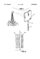
- FIG. 1 depicts an exemplary embodiment of a electromagnetic radiation detector in accordance with the present invention, illustrated from an oblique perspective.
- FIG. 2 depicts a portion of the radiation detector of FIG. 1, illustrated in lateral vertical cross-section.
- Electromagnetic radiation detector 10 is described herein in the context of a detector configured to detect radio frequency waves.
- Radio frequency (or "RF") propagations are generally considered to encompass electromagnetic waves at frequencies between 10 kHz and 100 GHz. Such frequency range is generally considered to be that in which EMF radiation may be detected and amplified as electric current at the wave frequency.
- Depicted detector 10 may be constructed in any convenient size. For example, a detecting area of approximately four inches by four inches may be satisfactory for many applications, such as evaluating RF shielding in consumer products.
- Detector 10 is depicted as having a handle 12 which is coupled to a detecting assembly, indicated generally at 14, to facilitate support and movement of detecting assembly 14 to a desired location and in a desired manner.
- Detecting assembly 14 preferably includes three primary components.
- the first component is an energy absorbing material or layer 16, which, for most applications, will be partially transparent to radio frequencies.
- Energy absorbing material 16 is coupled, such as through a heat conductive adhesive 18 to a thermally responsive visual imaging surface 20.
- visual imaging surface 20 will comprise a liquid crystal sheet.
- liquid crystal sheets are very transparent to radio frequencies.
- the heat conductive adhesive may be a conventional spray adhesive, such as an aerosol photo adhesive with thermal conductivity.
- energy absorbing material 16 includes a matrix of "KAPTON.”
- KAPTON is a polyimide material manufactured by DuPont Chemical Co.
- the KAPTON is impregnated with carbon particles to a degree sufficient to yield a desired sheet resistance.
- the sheet resistance will be between 1,000 and 5,000 ohms per square, and a sheet resistance of 2,000-3,500 ohms per square will be preferred for many applications.
- a resistivity level of approximately 3,000 ohms per square is desired.
- the carbon level within the KAPTON may be adjusted to vary the sheet resistance. The greater the desired sheet resistance, the lower the volume of carbon which will be provided within the KAPTON matrix.
- the sheet resistance will be selected in response to the power of RF to be detected. For example, the greater the power of the radiation source to be examined, the greater resistivity that can be utilized, and the lower the volume of carbon which is needed.
- a material such as carbon impregnated KAPTON is selected because it is relatively transparent to radio frequency waves.
- Such carbon impregnated KAPTON may be utilized in accordance with the present invention to absorb less than 0.5% of RF energy, and preferably to absorb a range of 0.125-0.25% of RF energy.
- Materials other than KAPTON may also be utilized within such an absorbency range.
- a sheet polyester material such as that sold under the tradename "MYLAR," also manufactured by DuPont Chemical Co. may be coated with carbon particles (in a manner similar to that of carbon paper) to provide an alternative energy absorbent layer.
- Carbon is a desirable RF absorbent for this application because it has a relatively low resistivity, and also will heat generally linearly in a response to absorption of RF radiation. Materials such as nitrides, however, may also be utilized as a RF absorbent medium.
- the RF absorbent medium will be selected to yield a thermal imprint which is resolvable by the thermal imaging surfaces.
- a temperature differential of 4-5 degrees of above ambient will typically be satisfactory.
- radio frequency emissions will contact the carbon particles in the KAPTON sheet or other surface, and will generate an incremental amount of heat in the particles. This heat is then transferred through adhesive 18 to the rearward surface 22 of liquid crystal sheet 20. Liquid crystal sheet 20 is responsive to the heat differential, and will transfer the pattern of the heat generated within the energy absorbing layer, thereby allowing the pattern of the impinging radio waves to viewed.
- Liquid crystal sheet 20 may have an operating temperature range between approximately 77° F. and 86° F. However, as is known to those skilled in the art, liquid crystal is manufactured in a variety of operating temperature ranges and other operating ranges may be used, as desired. If, for example, a detector was intended to be used outside, or in another potentially warm environment, then liquid crystal having range of approximately 88° F.-100° F. might be selected. Liquid crystal media will typically be able to resolve a thermal image in an ambient below the designated operating range.
Abstract
Description
Claims (29)
Priority Applications (1)
| Application Number | Priority Date | Filing Date | Title |
|---|---|---|---|
| US08/927,145 US6054848A (en) | 1997-09-03 | 1997-09-03 | Method and apparatus for detecting electromagnetic waves |
Applications Claiming Priority (1)
| Application Number | Priority Date | Filing Date | Title |
|---|---|---|---|
| US08/927,145 US6054848A (en) | 1997-09-03 | 1997-09-03 | Method and apparatus for detecting electromagnetic waves |
Publications (1)
| Publication Number | Publication Date |
|---|---|
| US6054848A true US6054848A (en) | 2000-04-25 |
Family
ID=25454267
Family Applications (1)
| Application Number | Title | Priority Date | Filing Date |
|---|---|---|---|
| US08/927,145 Expired - Lifetime US6054848A (en) | 1997-09-03 | 1997-09-03 | Method and apparatus for detecting electromagnetic waves |
Country Status (1)
| Country | Link |
|---|---|
| US (1) | US6054848A (en) |
Cited By (7)
| Publication number | Priority date | Publication date | Assignee | Title |
|---|---|---|---|---|
| US6657596B2 (en) * | 2002-01-30 | 2003-12-02 | Lucent Technologies Inc. | Method of measuring a pattern of electromagnetic radiation |
| US20040259507A1 (en) * | 2001-09-28 | 2004-12-23 | Erik Kohl | Communication terminal |
| US20070093983A1 (en) * | 2005-10-24 | 2007-04-26 | Han Chen | Mapping system and method for determining optimal radio transponder placement |
| WO2013055393A1 (en) * | 2011-10-03 | 2013-04-18 | The Marketing Store Worldwide, LP | Microwave energy indicator |
| CN105006656A (en) * | 2015-07-24 | 2015-10-28 | 哈尔滨工业大学 | Electric control scanning waveguide leaky-wave antenna based on liquid crystal |
| US9939478B1 (en) | 2011-06-21 | 2018-04-10 | The United States Of America As Represented By The Secretary Of The Navy | Passive radio frequency energy detector systems and methods |
| CN113125867A (en) * | 2021-03-24 | 2021-07-16 | 同济大学 | Full-field correction method for thermal pulse method response signal correction |
Citations (7)
| Publication number | Priority date | Publication date | Assignee | Title |
|---|---|---|---|---|
| US3693084A (en) * | 1969-06-17 | 1972-09-19 | Bendix Corp | Method and apparatus for detecting microwave fields |
| US4065655A (en) * | 1976-05-17 | 1977-12-27 | Canadian Patents And Development Limited | Microwave leakage indicator strip |
| US4431965A (en) * | 1981-04-16 | 1984-02-14 | The Narda Microwave Corporation | Microwave radiation monitor |
| US4467278A (en) * | 1981-08-27 | 1984-08-21 | Toth Emery K | Microwave oven leak detector |
| US5010251A (en) * | 1988-08-04 | 1991-04-23 | Hughes Aircraft Company | Radiation detector array using radiation sensitive bridges |
| US5164662A (en) * | 1991-07-22 | 1992-11-17 | Westinghouse Electric Corp. | Detection of radio frequency emissions |
| US5800960A (en) * | 1996-10-24 | 1998-09-01 | Eastman Kodak Company | Uniform background for color transfer |
-
1997
- 1997-09-03 US US08/927,145 patent/US6054848A/en not_active Expired - Lifetime
Patent Citations (7)
| Publication number | Priority date | Publication date | Assignee | Title |
|---|---|---|---|---|
| US3693084A (en) * | 1969-06-17 | 1972-09-19 | Bendix Corp | Method and apparatus for detecting microwave fields |
| US4065655A (en) * | 1976-05-17 | 1977-12-27 | Canadian Patents And Development Limited | Microwave leakage indicator strip |
| US4431965A (en) * | 1981-04-16 | 1984-02-14 | The Narda Microwave Corporation | Microwave radiation monitor |
| US4467278A (en) * | 1981-08-27 | 1984-08-21 | Toth Emery K | Microwave oven leak detector |
| US5010251A (en) * | 1988-08-04 | 1991-04-23 | Hughes Aircraft Company | Radiation detector array using radiation sensitive bridges |
| US5164662A (en) * | 1991-07-22 | 1992-11-17 | Westinghouse Electric Corp. | Detection of radio frequency emissions |
| US5800960A (en) * | 1996-10-24 | 1998-09-01 | Eastman Kodak Company | Uniform background for color transfer |
Cited By (11)
| Publication number | Priority date | Publication date | Assignee | Title |
|---|---|---|---|---|
| US20040259507A1 (en) * | 2001-09-28 | 2004-12-23 | Erik Kohl | Communication terminal |
| US6657596B2 (en) * | 2002-01-30 | 2003-12-02 | Lucent Technologies Inc. | Method of measuring a pattern of electromagnetic radiation |
| US20070093983A1 (en) * | 2005-10-24 | 2007-04-26 | Han Chen | Mapping system and method for determining optimal radio transponder placement |
| WO2007048654A2 (en) * | 2005-10-24 | 2007-05-03 | International Business Machines Corporation | Mapping system and method for determining optimal radio transponder placement |
| WO2007048654A3 (en) * | 2005-10-24 | 2007-07-12 | Ibm | Mapping system and method for determining optimal radio transponder placement |
| US7541925B2 (en) | 2005-10-24 | 2009-06-02 | International Business Machines Corporation | Mapping system and method for determining optimal radio transponder placement |
| US9939478B1 (en) | 2011-06-21 | 2018-04-10 | The United States Of America As Represented By The Secretary Of The Navy | Passive radio frequency energy detector systems and methods |
| WO2013055393A1 (en) * | 2011-10-03 | 2013-04-18 | The Marketing Store Worldwide, LP | Microwave energy indicator |
| CN105006656A (en) * | 2015-07-24 | 2015-10-28 | 哈尔滨工业大学 | Electric control scanning waveguide leaky-wave antenna based on liquid crystal |
| CN105006656B (en) * | 2015-07-24 | 2017-09-29 | 哈尔滨工业大学 | Automatically controlled scanning wave guide wave leakage antenna based on liquid crystal |
| CN113125867A (en) * | 2021-03-24 | 2021-07-16 | 同济大学 | Full-field correction method for thermal pulse method response signal correction |
Similar Documents
| Publication | Publication Date | Title |
|---|---|---|
| US6054848A (en) | Method and apparatus for detecting electromagnetic waves | |
| EP0029451B1 (en) | Passive remote temperature sensor system | |
| US3931573A (en) | Radiation detector | |
| CN105917521A (en) | Radiofrequency-wave-transparent capacitive sensor pad | |
| WO1998010632A1 (en) | Highly heat-conductive composite magnetic material | |
| US20060289525A1 (en) | Microwave leakage indicator card | |
| CN110658240A (en) | Toxic and harmful gas detection sensor and detection method | |
| US5285164A (en) | Electromagnetic radiation measurement apparatus | |
| US6994468B2 (en) | Heat flux comparator | |
| US4247299A (en) | Non-conductive polar gas sensing element and detection system | |
| US4051435A (en) | Microwave field detector | |
| WO2018223676A1 (en) | Microwave cooking device | |
| US5576696A (en) | Personal radiation hazard meter | |
| CN210923557U (en) | Poisonous and harmful gas detection sensor | |
| CN108508263B (en) | Power sensor | |
| Sega et al. | Measured internal coupled electromagnetic fields related to cavity and aperture resonance | |
| Norgard | Infrared/microwave correlation measurements | |
| CN110568383B (en) | Magnetic field detection device based on magnetocaloric effect | |
| RU2606516C2 (en) | Pyroelectric millimeter radiation detector (versions) | |
| CN108508264B (en) | Power sensor | |
| CN218724836U (en) | Thermocouple structure of infrared energy furnace containing graphene coated glass | |
| MacLatchy et al. | A simple technique for measuring high microwave electric field strengths | |
| CN102539339A (en) | Terahertz wave detector | |
| GB2218261A (en) | Thermoelectric device | |
| CN110086550B (en) | Full-temperature OTA testing device and method |
Legal Events
| Date | Code | Title | Description |
|---|---|---|---|
| STCF | Information on status: patent grant |
Free format text: PATENTED CASE |
|
| REMI | Maintenance fee reminder mailed | ||
| FPAY | Fee payment |
Year of fee payment: 4 |
|
| SULP | Surcharge for late payment | ||
| AS | Assignment |
Owner name: MISSION RESEARCH CORPORATION, CALIFORNIA Free format text: ASSIGNMENT OF ASSIGNORS INTEREST;ASSIGNOR:TORRES, ALFONSO R.;REEL/FRAME:017870/0871 Effective date: 19970818 |
|
| AS | Assignment |
Owner name: BANK OF AMERICA, N.A., NORTH CAROLINA Free format text: SECURITY AGREEMENT;ASSIGNORS:AMMUNITION ACCESSORIES INC.;ATK COMMERCIAL AMMUNITION COMPANY INC.;ATK COMMERCIAL AMMUNITION HOLDINGS COMPANY INC.;AND OTHERS;REEL/FRAME:019733/0757 Effective date: 20070329 Owner name: BANK OF AMERICA, N.A.,NORTH CAROLINA Free format text: SECURITY AGREEMENT;ASSIGNORS:AMMUNITION ACCESSORIES INC.;ATK COMMERCIAL AMMUNITION COMPANY INC.;ATK COMMERCIAL AMMUNITION HOLDINGS COMPANY INC.;AND OTHERS;REEL/FRAME:019733/0757 Effective date: 20070329 |
|
| FPAY | Fee payment |
Year of fee payment: 8 |
|
| REMI | Maintenance fee reminder mailed | ||
| AS | Assignment |
Owner name: ALLIANT TECHSYSTEMS INC., MINNESOTA Free format text: MERGER;ASSIGNOR:MISSION RESEARCH CORPORATION;REEL/FRAME:020710/0453 Effective date: 20060927 |
|
| AS | Assignment |
Owner name: BANK OF AMERICA, N.A., CALIFORNIA Free format text: SECURITY AGREEMENT;ASSIGNORS:ALLIANT TECHSYSTEMS INC.;AMMUNITION ACCESSORIES INC.;ATK COMMERCIAL AMMUNITION COMPANY INC.;AND OTHERS;REEL/FRAME:025321/0291 Effective date: 20101007 |
|
| FPAY | Fee payment |
Year of fee payment: 12 |
|
| AS | Assignment |
Owner name: BANK OF AMERICA, N.A., CALIFORNIA Free format text: SECURITY AGREEMENT;ASSIGNORS:ALLIANT TECHSYSTEMS INC.;CALIBER COMPANY;EAGLE INDUSTRIES UNLIMITED, INC.;AND OTHERS;REEL/FRAME:031731/0281 Effective date: 20131101 |
|
| AS | Assignment |
Owner name: WELLS FARGO BANK, NATIONAL ASSOCIATION, AS ADMINISTRATIVE AGENT, NORTH CAROLINA Free format text: SECURITY AGREEMENT;ASSIGNORS:ORBITAL ATK, INC.;ORBITAL SCIENCES CORPORATION;REEL/FRAME:036732/0170 Effective date: 20150929 Owner name: WELLS FARGO BANK, NATIONAL ASSOCIATION, AS ADMINIS Free format text: SECURITY AGREEMENT;ASSIGNORS:ORBITAL ATK, INC.;ORBITAL SCIENCES CORPORATION;REEL/FRAME:036732/0170 Effective date: 20150929 |
|
| AS | Assignment |
Owner name: ORBITAL ATK, INC. (F/K/A ALLIANT TECHSYSTEMS INC.), VIRGINIA Free format text: RELEASE BY SECURED PARTY;ASSIGNOR:BANK OF AMERICA, N.A.;REEL/FRAME:036816/0624 Effective date: 20150929 Owner name: FEDERAL CARTRIDGE CO., MINNESOTA Free format text: RELEASE BY SECURED PARTY;ASSIGNOR:BANK OF AMERICA, N.A.;REEL/FRAME:036816/0624 Effective date: 20150929 Owner name: EAGLE INDUSTRIES UNLIMITED, INC., MISSOURI Free format text: RELEASE BY SECURED PARTY;ASSIGNOR:BANK OF AMERICA, N.A.;REEL/FRAME:036816/0624 Effective date: 20150929 Owner name: ORBITAL ATK, INC. (F/K/A ALLIANT TECHSYSTEMS INC.) Free format text: RELEASE BY SECURED PARTY;ASSIGNOR:BANK OF AMERICA, N.A.;REEL/FRAME:036816/0624 Effective date: 20150929 Owner name: AMMUNITION ACCESSORIES, INC., ALABAMA Free format text: RELEASE BY SECURED PARTY;ASSIGNOR:BANK OF AMERICA, N.A.;REEL/FRAME:036816/0624 Effective date: 20150929 Owner name: ALLIANT TECHSYSTEMS INC., VIRGINIA Free format text: RELEASE BY SECURED PARTY;ASSIGNOR:BANK OF AMERICA, N.A.;REEL/FRAME:036816/0624 Effective date: 20150929 |
|
| AS | Assignment |
Owner name: ORBITAL ATK, INC., VIRGINIA Free format text: TERMINATION AND RELEASE OF SECURITY INTEREST IN PATENTS;ASSIGNOR:WELLS FARGO BANK, NATIONAL ASSOCIATION, AS ADMINISTRATIVE AGENT;REEL/FRAME:046477/0874 Effective date: 20180606 |