US6137585A - Method and apparatus for recording three-dimensional distribution of light backscattering potential in transparent and semi-transparent structures - Google Patents
Method and apparatus for recording three-dimensional distribution of light backscattering potential in transparent and semi-transparent structures Download PDFInfo
- Publication number
- US6137585A US6137585A US09/079,495 US7949598A US6137585A US 6137585 A US6137585 A US 6137585A US 7949598 A US7949598 A US 7949598A US 6137585 A US6137585 A US 6137585A
- Authority
- US
- United States
- Prior art keywords
- measurement
- interferometer
- light
- path
- arm
- Prior art date
- Legal status (The legal status is an assumption and is not a legal conclusion. Google has not performed a legal analysis and makes no representation as to the accuracy of the status listed.)
- Expired - Lifetime
Links
Images


Classifications
-
- A—HUMAN NECESSITIES
- A61—MEDICAL OR VETERINARY SCIENCE; HYGIENE
- A61B—DIAGNOSIS; SURGERY; IDENTIFICATION
- A61B3/00—Apparatus for testing the eyes; Instruments for examining the eyes
- A61B3/10—Objective types, i.e. instruments for examining the eyes independent of the patients' perceptions or reactions
- A61B3/102—Objective types, i.e. instruments for examining the eyes independent of the patients' perceptions or reactions for optical coherence tomography [OCT]
-
- A—HUMAN NECESSITIES
- A61—MEDICAL OR VETERINARY SCIENCE; HYGIENE
- A61B—DIAGNOSIS; SURGERY; IDENTIFICATION
- A61B3/00—Apparatus for testing the eyes; Instruments for examining the eyes
- A61B3/10—Objective types, i.e. instruments for examining the eyes independent of the patients' perceptions or reactions
- A61B3/12—Objective types, i.e. instruments for examining the eyes independent of the patients' perceptions or reactions for looking at the eye fundus, e.g. ophthalmoscopes
-
- G—PHYSICS
- G01—MEASURING; TESTING
- G01B—MEASURING LENGTH, THICKNESS OR SIMILAR LINEAR DIMENSIONS; MEASURING ANGLES; MEASURING AREAS; MEASURING IRREGULARITIES OF SURFACES OR CONTOURS
- G01B11/00—Measuring arrangements characterised by the use of optical techniques
- G01B11/24—Measuring arrangements characterised by the use of optical techniques for measuring contours or curvatures
- G01B11/2441—Measuring arrangements characterised by the use of optical techniques for measuring contours or curvatures using interferometry
-
- G—PHYSICS
- G01—MEASURING; TESTING
- G01B—MEASURING LENGTH, THICKNESS OR SIMILAR LINEAR DIMENSIONS; MEASURING ANGLES; MEASURING AREAS; MEASURING IRREGULARITIES OF SURFACES OR CONTOURS
- G01B11/00—Measuring arrangements characterised by the use of optical techniques
- G01B11/24—Measuring arrangements characterised by the use of optical techniques for measuring contours or curvatures
- G01B11/255—Measuring arrangements characterised by the use of optical techniques for measuring contours or curvatures for measuring radius of curvature
Definitions
- the present invention relates generally to determining light backscattering at various depths in transparent and semi-transparent structures, and more particularly to methods and apparatus for diagnosing human eye conditions by detecting the reflection of light from various layers in the eye.
- German Patent No. 3201801A1 to Fercher discloses a method referred to as partial coherence interferometry ("PCI") in which light having a short coherence length is combined with a Michelson interferometer to locate the positions of reflecting surfaces within an object.
- PCI partial coherence interferometry
- a measurement light beam from the interferometer is directed against a particular reflecting surface in the object, and a reference light beam is directed against a known reference surface.
- the position of the reflecting surface in the object is determined by matching the length of the known reference path that is traversed by the reference light beam to the unknown object path length that is traversed by the measurement light beam.
- optical A-scans which can be thought of as plots of backscattered light intensity as a function of depth within the object.
- OCT optical coherence tomography
- the invention disclosed in the '501 patent is embodied in the commercial OCT instrument sold by Humphrey Instruments/Carl Zeiss.
- the Humphrey-Zeiss instrument permits measuring only longitudinal sections, not transverse sections, and furthermore it requires that the section geometry be defined a priori.
- the present invention understands that it is desirable to measure both longitudinal and transverse sections to thereby generate a three dimensional map of the object, and that it is also desirable that the section geometry not be defined a priori.
- the present invention recognizes that because the reference surface of the Humphrey-Zeiss instrument is not part of the object to be measured, the precision of the instrument can be degraded by axial movement of the object during measurement.
- the present invention recognizes that the speed of measurement of prior instruments is relatively slow, and that prolonged measurement time has undesirable consequences, as set forth in the following discussion.
- the object path length is matched with the reference path length in PCI applications, including OCT. This matching, when it occurs, is indicated by the presence of interference fringes caused by the interference of the return reference beam with the return measurement beam.
- the interference fringes were visually detected, which significantly lengthened the time required to gather the backscattering data at the various layer depths.
- prolonged data gathering periods limits the resolution of the data when the object being analyzed moves. In the case of the human eye, microsaccidic eye movements tend to limit the resolution of the data.
- Hitzenberger et al. in an article entitled “Eye Length Measurement by Laser Doppler Interferometry ("LDI")", Int'l Conf. on Optics within Life Sciences, Garmisch-Partenmaschinen, 1990, propose detecting the fringes by heterodyning.
- the Hitzenberger et al. article discloses moving a reference mirror at constant speed to cause a Doppler frequency shift in one of the beams, causing the generation of a detectable "beat" frequency when the reference beam and measurement beam interfere with each other as they return from the object being measured.
- the use of mechanically moving parts nevertheless limits the speed of measurement by limiting the magnitude of the induced frequency shift, which is proportional to the speed of the reference mirror.
- the present invention recognizes that mechanically-based heterodyning techniques can induce a varying beat frequency, causing demodulation complications, and also requiring a relatively large filter bandwidth (used during demodulation) to account for the variations. The large filter bandwidth in turn reduces the signal to noise ratio of the instrument.
- an object of the present invention to provide a method and apparatus for generating a map of a transparent or semi-transparent object. Another object of the present invention is to provide a method and apparatus for rapidly generating a map of a human eye. Still another object of the present invention is to provide a method and apparatus for rapidly generating a map of a human eye that is easy to use and cost-effective, and that is not degraded by axial motion of the eye during measurement.
- An apparatus for detecting the distribution of light backscattering potential in an object, such as a human eye.
- the apparatus includes an interferometer which emits plural preferably short coherence-length light beams, with at least one of the light beams being directable toward the object.
- the light beams are reflected by respective surfaces to establish respective reflected light beams.
- At least one non-moving frequency shifter is positioned in at least one path of the light beams, and a receiver receives the reflected beams and generates a signal representative thereof.
- the signal is usable for determining light backscattering sites in the object.
- the plural light beams include at least a reference beam directed at a reference surface defined by the object and a measurement beam directed at a measurement site defined by the object.
- the frequency shifter changes the frequency of light beams passing therethrough.
- the frequency shifter is selected from the group of frequency shifters including acousto-optic frequency shifters, and phase modulators.
- the interferometer defines a reference arm and a measurement arm, and a first difference is established between the lengths of the arms.
- the reference beam travels a reference distance relative to the object
- the measurement beam travels a measurement distance relative to the object
- a second difference is established between the reference distance and measurement distance.
- At least one arm length can then be established such that the first difference bears a proportional relationship to the second difference, and a beat frequency is received by the receiver when the differences are substantially matched.
- the interferometer includes at least one translationally movable path delay unit to selectively establish the at least one arm length.
- polarized light can be used.
- a polarizer can be positioned in the light entrance path of the interferometer, and a half wave plate can be positioned in the arm of the interferometer in which the frequency shifter is positioned. Also, a quarter wave plate can be positioned in the light exit path.
- At least one spatial filter can be disposed in at least one of the arms to improve the quality of a wave front of light passing therethrough.
- a scanning mirror is positioned in the measurement arm and is tiltable in at least one degree of freedom to selectively establish a direction of propagation of the measurement beam.
- a coherence layer correcting element is juxtaposed with the scanning mirror to alter a length of a path traversed by the measurement beam in proportion to an angle established between the measurement beam and its null direction, typically the direction of the reference beam.
- an apparatus for matching an object path difference with an interferometer path difference and identifying the matching by heterodyne detection of a reference beam and a measurement beam includes means for shifting the frequency of at least one of: the reference beam, and the measurement beam, by at least ten megaHertz. Thereby, a beat frequency is generated when the object path difference bears a predetermined relationship to an interferometer path difference.
- a method for generating data representative of a three-dimensional distribution of the light backscattering potential of an object defining at least one reference surface and plural measurement sites.
- the method includes directing a reference beam from a reference arm of an interferometer against the reference surface, and also directing a measurement beam from a measurement arm of the interferometer against the measurement site.
- the method further includes shifting the frequency of at least one beam by at least ten megaHertz. Reflections of the beams from the surfaces are combined and detected.
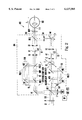
- FIG. 1 is a schematic diagram of a first embodiment of the present invention using a Michelson interferometer, showing the measurement mirror in a null position in phantom and showing the measurement mirror in a measurement position in solid lines;
- FIG. 2 is a schematic diagram of a second embodiment of the present invention using a modified Mach-Zehnder interferometer
- FIG. 3 is a schematic diagram of an alternate embodiment of a portion of the apparatus shown in FIG. 2, showing a coherence layer correcting element and showing a coherence layer in solid lines as it would appear without the correcting element, and showing the coherence layer in dashed lines as it would appear with the correcting element;
- FIG. 4 is a block diagram of the electrical control components
- FIG. 5 is a flow chart of the process used by the apparatus to generate a three-dimensional map of an object.
- an apparatus for generating data representative of the three-dimensional distribution of light backscattering sites, and their respective reflectivities, in a transparent or semi-transparent object 12, such as a human eye. That is, the apparatus 10 measures the reflection of light by various sites within the object 12 along the longitudinal axis, i.e., z-axis, with the understanding that the z-axis is orthogonal to the transverse axes, i.e., the x and y axes. It is to be understood, however, that the apparatus 10 can be used to generate data representative of the three-dimensional distribution of light backscattering potential in objects other than eyes.
- FIG. 1 shows a simplified embodiment that uses a Michelson interferometer 14.
- a short coherence, broadband light source LS directs a beam of light into an entrance path 16 of the interferometer 14.
- the light source LS includes a superluminescent diode and collimating optics.
- Light propagating along the entrance path 16 impinges upon an entrance beamsplitter BS, which splits the beam into a reference beam propagating along a reference arm or path 18 and a measurement beam propagating along a measurement arm or path 20.
- the reference beam is reflected by a reference mirror M back to the entrance beamsplitter BS, through which it propagates along a dual beam path DB to an exit beamsplitter BS'.
- the measurement beam is reflected by a measurement mirror M' back to the entrance beamsplitter BS, which reflects the measurement beam to propagate along the dual beam path DB to the exit beamsplitter BS' such that the reference beam and the measurement beam form a coaxial dual beam.
- At least the measurement mirror M' is translationally movable between a null position, indicated by dashed lines in FIG. 1, and plural measurement positions (only a single measurement position shown and indicated in solid lines in FIG. 1).
- the distance traversed by the measurement beam through the interferometer 14 is equal to the distance traversed by the reference beam through the interferometer 14.
- the measurement mirror M' when the measurement mirror M' is in a measurement position that is distanced from the null position by an interferometer differential distance of "d", the distance traversed by the measurement beam through the interferometer 14 is equal to the distance traversed by the reference beam through the interferometer 14, plus two times "d". In this latter case, an interferometer optical path difference of magnitude "2d" is established between the distances traversed by the reference and measurement beams through the interferometer 14. It is to be understood that the measurement mirror M' need not actually be moved to the null position, once it is known, but rather need only be movable to the various measurement positions.
- At least one frequency shifter FS is positioned in at least one of the arms 18, 20.
- the frequency shifter FS is positioned in the reference arm 18, but it is to be understood that the frequency shifter FS can be positioned in the measurement arm 20 or that a second frequency shifter (not shown) can be positioned in the measurement arm 20.
- the frequency shifter FS shifts the frequency of light propagating through it by an amount ⁇ f to facilitate heterodyne detection of interference fringes caused by the interference of the reference beam with the measurement beam after the beams have been reflected by the object 12.
- the detection of such fringes indicates that the interferometer optical path difference, discussed above, matches the object optical path difference between the reference and measurement beams within the object 12, discussed more fully below.
- match is meant that the two optical path differences bear a predetermined proportional relationship to each other, e.g., one to one.
- the precision of the match is on the order of the coherence length of the light source.
- the frequency shifter FS is non-moving.
- non-moving is meant functionally non-moving, i.e., that the frequency shifter FS preferably does not have to be moved to shift the frequency of light.
- the frequency shifter FS can be established by, e.g, an acousto-optic frequency shifter or a phase modulator.
- the frequency shifter FS can be established by a moving mirror, a moving cube, a moving glass plate, a moving beam splitter, a moving retroreflector, or a moving lens, provided that the frequency shifter FS can be moved sufficiently quickly to generate a heterodyne beat frequency of at least ten million Hertz (10 MHz), and more preferably a heterodyne beat frequency of at least forty million Hertz (40 MHz).
- the beams from the interferometer 14 are reflected by the exit beam splitter BS' out of the interferometer 14 and along an object path 22, toward the object 12. Both beams are reflected by a strongly reflecting reference surface of the object 12, preferably the anterior surface 24. However, if the anterior surface 24 is insufficiently reflective, a glass plate (not shown) or other highly reflective yet transmissive object can be positioned in front of the object 12 at a fixed distance to it to function as the reference surface.
- both beams are reflected by measurement sites along the z-axis within the object 12.
- FIG. 1 shows one such measurement site 26 that is distanced from the reference surface 24 by an object differential distance "z". It is the purpose of the present invention to measure the various object differential distances "z" from the reference surface 24 to the various internally reflective measurement sites 26 of the object 12. Moreover, the present invention not only measures the distances from the reference surface 24 to the various measurement sites 26, but also measures the backscattering potential (i.e., reflectivity) of the various measurement sites 26. All of the reflected beams propagate back through the exit beamsplitter BS' and can be focussed on a receiver, such as a photodetector PD, by a lens L1.
- a receiver such as a photodetector PD
- the interferometer differential distance "d" equals one of the object differential distances "z"
- the corresponding reflected reference beam from the reference surface 24 and reflected measurement beam from the measurement site 26 will interfere.
- the frequency shifter FS shifted the frequency of one of the beams by an amount ⁇ f
- the beat signal is converted to an electrical signal by the photodetector PD.
- the signal is then sent to a signal processor SP for demodulation.
- the demodulation can be undertaken by band pass filtering the signal with a filter centered on ⁇ f and detecting its envelope, the magnitude of which is related to the backscattering potential of the measurement site 26 of interest.
- the signal is converted to digital format by an analog to digital converter AD, and then stored in a computer PC for correlating the processed signal to a measurement site having depth "z" relative to the reference surface 24 and a backscattering potential as represented by the contrast of the interference fringes, using correlation principles understood in the art.
- the beat signal can be immediately converted to a digital signal and then processed numerically by a computer or digital signal processor.
- the measurement mirror M' is positioned at various locations to establish various values for the interferometer differential distance "d", with the interference fringes being recorded (or not) at each position as indicative of whether and how strong a backscattering site exists at a distance "z" from the reference surface 24 in the object 12. Since both the reference beam and measurement beam are reflected by the object 12, the apparatus 10 is insensitive to axial motion of the object 12 during measurement.
- the backscattering sites at a distance "z" from the reference surface 24 are all in a common “coherence layer” at distance "z".
- coherence layer is meant that layer within the object sought to be mapped whose distance to the reference point (the point on the object at which the reference beam is reflected) is equal to the interferometer path length difference. Any backscattering structure within the coherence layer will reflect the measurement beam such that it interferes with the reference beam.
- the position of the coherence layer is determined by the value of the interferometer path difference, and the curvature of the coherence layer is determined by the geometry of the light path.
- either the object 12 or the measurement beam can be moved in a raster scan for each interferometer differential distance "d".
- the beat frequency ⁇ f should be larger than the frequencies caused by intensity variations during the raster scanning, which can be caused by locally varying areas within the coherence layer.
- the present invention preferably uses a non-moving frequency shifter FS, because such a frequency shifter is better able to produce relatively large beat frequencies ⁇ f than are moving Doppler-type devices.
- FIG. 2 a particularly preferred embodiment of the present apparatus is shown, generally designated 100, for generating data representative of the three-dimensional distribution of light backscattering sites and their reflectivity in a transparent or semi-transparent object 102, such as a human eye.
- a transparent or semi-transparent object 102 such as a human eye.
- the apparatus 100 shown in FIG. 2 is identical in operation and purpose to the apparatus 10 shown in FIG. 1, with the exceptions noted below.
- the apparatus 100 uses a Mach-Zehnder interferometer 104, which establishes a base on which the below-disclosed components are movably or fixedly mounted as set forth herein.
- the use of such an interferometer facilitates processing the two beam components independently of each other such that each component can be focussed independently of the other at its own respective depth within the object 102, and such that parallel wave fronts of the return beams can be obtained at the photodetector.
- the apparatus 100 includes a short coherence, broadband light source LS that directs a beam of light into an entrance path 106 of the interferometer 104.
- a polarizer P is positioned in the entrance path 106 or other appropriate location between the light source LS and frequency shifter.
- a fixed reference mirror M 1 First considering the reference arm of the interferometer 104, light propagating along the reference arm 108 is reflected by a fixed reference mirror M 1 toward a first polarizing beamsplitter PBS 1.
- the polarizing beamsplitters discussed herein are used only when polarized light is used, so that the reference beam traverses the frequency shifter only once; otherwise, the polarizing beamsplitters can be replaced with respective mirrors. In the latter case, the frequency shifter is positioned anywhere in the reference beam, or indeed any where in the measurement beam.
- the first polarizing beamsplitter PBS 1 permits light from the reference mirror M 1 to pass therethrough. Owing to the polarization of the light effected by the polarizer P, substantially none of the reference beam from the reference mirror M 1 is reflected by the first polarizing beamsplitter PBS1.
- the reference beam continues from the beamsplitter PBS 1 to at least one preferably non-moving frequency shifter FS, where its frequency is shifted in accordance with principles discussed previously. Then, the reference beam may pass through an optionally rotatable half wave plate HWP, which rotates the polarization of the reference beam to its original orientation or other desired orientation.
- the half wave plate HWP is necessary only if the frequency shifter FS rotates the polarization plane of the frequency shifted beam, such as might occur for certain types of frequency shifters, e.g., AO frequency shifters.
- the half wave plate HWP is oriented in the appropriate position it is not necessary to further rotate the half wave plate HWP.
- the reference beam propagates through a second polarizing beamsplitter PBS 2, it being understood that the second polarizing beamsplitter PBS 2 is configured for permitting substantially all light having the polarization of the reference beam to pass therethrough, without reflecting the light.
- the second polarizing beamsplitter PBS 2 can be replaced by a mirror.
- a reference spatial filter S 1 is positioned in the reference arm 108.
- the reference spatial filter S 1 includes a first reference lens L 5 that focusses light onto an aperture 112 in a reference aperture plate A 1, and a second reference lens L 6 that receives light from the aperture plate and in turn focusses the light onto the reference surface of the object 102 (the vertex of the cornea when the object 102 is a human eye).
- the reference surface of the object 102 is an anterior surface 114 of the object 102.
- reference beams returning from the object 102 are focussed by the second reference lens L 6 onto the aperture 112, and when the return reference beam is diffracted through the aperture 112, it passes through the first reference lens L 5, which refracts the beam to have a plane parallel wave front.
- the reference beam propagates to an exit beamsplitter BS 2, where it is transmissively passed out of the interferometer 104 to an object path 116.
- a quarter wave plate QWP is positioned in the object path 116 as shown.
- the reference beam propagates to the object 102, where at least a portion of the reference beam is reflected by the reference surface 114 of the object 102 and back along the path just described. Specifically, the reflected reference beam passes through the quarter wave plate QWP, exit beamsplitter BS 2, and back into the reference arm or path 108 of the interferometer 104. As discussed above, the return reference beam is conditioned by the reference spatial filter S 1, and then the return reference beam propagates to the second polarizing beamsplitter PBS 2.
- the return beam is substantially completely reflected by the second polarizing beamsplitter PBS 2 to a reference path delay unit PDU 1.
- the reference path delay unit PDU 1 includes first and second reference delay mirrors M 3, M 2, with the return beam being reflected by the first reference delay mirror M 3 to the second reference delay mirror M 2.
- the second reference delay mirror M 2 reflects the beam to the first polarizing beamsplitter PBS1, and then back along the remainder of the reference arm 108 to the entrance beamsplitter BS 1. It may now be appreciated that owing to above-described cooperation of structure, the reference beam passes through the non-moving frequency shifter FS only once.
- the reference path delay unit PDU 1 is translationally movable in the directions indicated by the arrows 118, to establish a reference path length differential distance d, as shown.
- Suitable means such as a small servo, can be used to move the reference path delay unit PDU 1.
- the light passes through an exit lens L 1, which focusses the light onto a photodetector PD for subsequent processing by a signal processor SP, analog to digital converter AD, and computer PC as described above in reference to FIG. 1.
- beam components exiting the entrance beamsplitter BS 1 have parallel wave fronts and can be focussed at the photodetector PD, in which case the beams are confocal to their respective conjugate points at or within the object 102.
- beam components propagating back through the contralateral interferometer path will not have parallel wave fronts when they exit the entrance beamsplitter BS 1 and consequently will not pass the confocal aperture that is effectively in front of the photodetector PD. Accordingly, beam components propagating back through the contralateral interferometer path will not be used for the interferometric distance measurements.
- the measurement path delay unit PDU 2 includes first and second measurement delay mirrors M 9, M 8, with the beam being reflected by the first measurement delay mirror M 9 to the second measurement delay mirror M 8.
- the second measurement delay mirror M 8 reflects the beam to a second fixed measurement path mirror M 7. It is to be understood that designations M 8, M 9 can alternatively be replaced by a retroreflector that can be used in lieu of first and second measurement delay mirrors.
- the measurement path delay unit PDU 2 can be translationally movable in the directions indicated by the arrows 120, to establish a measurement path length differential distance d 2 as shown.
- a measurement path length differential distance d 2 By providing two path delay units PDU 1, PDU 2, the detection of measurement sites that are close to the reference surface 114 of the object 102 (i.e., that are shallow) is facilitated.
- Suitable means such as a small servo, can be used to move the measurement path delay unit PDU 2.
- FIG. 2 shows that the light from the second measurement path mirror M 7 propagates to a dispersion compensation element DC.
- the dispersion compensation element DC is configured to compensate for the net difference of the group dispersive effects of the optical elements in the two arms 108, 110, and those caused by the different path lengths within the object 102. In so doing, the dispersion compensation element DC improves the axial resolution of the apparatus 100.
- the dispersion compensation element DC is established by two wedge-shaped glass plates juxtaposed as shown, with at least one of the wedges being movable in the directions indicated by the arrows ⁇ to establish the distance through which the light must pass through the wedges, to thereby compensate for dispersive effects.
- FIG. 2 shows the dispersion compensation element DC positioned in the measurement arm 110
- the dispersion compensation element DC is positioned in the reference arm 108.
- a respective dispersion compensation element can be positioned in each arm 108, 110 of the interferometer 104.
- a measurement spatial filter S 2 is positioned in the measurement arm 110.
- the measurement spatial filter S 2 is in all essential respects identical in construction and operation to the reference spatial filter S 1 discussed above. Accordingly, the measurement spatial filter S 2 includes a first measurement lens L 2 that focusses light onto an aperture 122 in a measurement aperture plate A 2, and a second measurement lens L 3 that receives light from the aperture plate and in turn directs the light onto a scanning mirror M 4.
- the scanning mirror M 4 scans the measurement beam across the particular coherence layer sought to be mapped in the object 102.
- the mirror M 4 is tiltably moved about both the x-axis and y-axis in a raster scan, as indicated by the x arrows and y arrows, which are shown orthogonal to each other in FIG. 2.
- the scanning mirror M 4 is movably mounted on the interferometer 104 by suitable means, e.g., a gimbal, for permitting tiltable motion of the mirror M 4 in two degrees of freedom.
- two mirrors can be used in lieu of the scanning mirror M 4, each being tiltable in a single degree of freedom.
- One or more servos can be used to move the scanning mirror M 4.
- the scanning mirror M 4 reflects the measurement beam to a measurement exit lens L 4.
- the measurement beam propagates through the lens L 4 to the exit beamsplitter BS 2, and thence onto the object 102.
- the measurement beam is reflected by a measurement site in the object 102 (e.g., the retina or deeper layers of the ocular fundus when the object 102 is a human eye), and returns via the measurement path or arm 110 just described to the photodetector PD.
- the measurement path lenses L 3 and L 4 in cooperation with the refractive elements of the object 102, focus the measurement beam onto the desired measurement site. Refractive errors of the object 102, e.g., a human eye, can be accommodated for using additional measurement path lenses (not shown), or with movable lenses or lenses having variable focal lengths. In any case, the focal length of the measurement exit lens L 4 is established to image the pivot point of the scanning mirror M 4 substantially onto the nodal point of the object 102.
- either or both of the measurement path lenses L 3, L 4 can be translationally moved, e.g., by servos, or have their focal lengths changed, in consonance with varying the interferometer path delay, to focus the beam onto the measurement site sought to be detected.
- the interferometer path difference 2d 1 -4d 2 (plus differences that are attributable to different optical elements in one path 108, 110 vis-a-vis the other path 110, 108.)
- the interferometer path difference 4d 1 -4d 2 (plus differences that are attributable to different optical elements in one path 108, 110 vis-a-vis the other path 110, 108.)
- FIG. 3 shows an additional detail of the interferometer 104. Because the transversal distribution of backscattering sites is determined by moving the scanning mirror M 4 to tilt the measurement beam as described above, the coherence layer within the object will be curved. In the case of the human eye, the curvature of the coherence layer can be different from the curvature of the surfaces (e.g., the retina) to be measured, as shown in solid lines in FIG. 3. The present invention recognizes that the light path of the measurement beam be established such that the curvature of the coherence layer is about equal to the curvature of structures, e.g., the retina, sought to be imaged.
- the curvature of the coherence layer is about equal to the curvature of structures, e.g., the retina, sought to be imaged.
- a coherence layer correcting element CLC can be positioned between the scanning mirror M 4 and the lens L 4 to alter the optical path length of the tilted measurement beam as a function of the scanning angle, thereby effectively altering the curvature of the coherence layer to match that of the surfaces to be measured as shown in dashed lines in FIG. 3.
- the coherence layer correcting element CLC is a glass plate.
- the coherence layer correcting element can be two glass wedges similar to the dispersion compensation element DC, with the understanding that the wedges can be moved (e.g., by servos or other means) to establish their relative transversal position as appropriate for the scan angle and for the curvature of the measured surface.
- FIG. 4 shows that the computer PC can control various components within the interferometer 104 in accordance with the principles discussed above. More particularly, the computer PC can send signals to a digital to analog converter (DAC) 124 to control one or more servos 126 for moving the scanning mirror M 4, in accordance with the disclosure above. Also, the computer PC can send signals to a digital to analog converter (DAC) 128 to control one or more servos 130 for translationally moving the reference path delay unit PDU 1, in accordance with the disclosure above. Moreover, the computer PC can send signals to a digital to analog converter (DAC) 132 to control one or more servos 134 for translationally moving the measurement path delay unit PDU 2, in accordance with the disclosure above.
- DAC digital to analog converter
- the computer PC can send signals to a digital to analog converter (DAC) 136 to control one or more servos 138 for moving one or more of the lenses and/or coherence layer correcting element CLC and/or dispersion compensating element in accordance with the disclosure above.
- DAC digital to analog converter
- FIG. 5 illustrates the logic undertaken by the computer PC in generating data that is useful for rendering a three-dimensional map of a transparent or semi-transparent object.
- consecutive coherence layers are sequentially raster scanned, with the distance between coherence layers being about equal to the coherence length of the light source.
- a start and an end value, as well as an incremental step length of the interferometer path length differential are defined.
- the logic undertakes the following steps.
- the scanning mirror M 4 is controlled, using the scanning mirror servo 126, to move the measurement beam in a raster scan as disclosed.
- the contrast of the interference fringes for the present value of the path length differential is recorded.
- the logic moves to block 146 to increment the interferometer path length differential by the step length by signalling one or both of the PDU servos 130, 134 to move.
- the logic then loops back to block 142 to raster scan the new coherence layer. These steps are repeated until the end value of the interferometer path length differential is reached.
Abstract
Description
Claims (9)
Priority Applications (8)
| Application Number | Priority Date | Filing Date | Title |
|---|---|---|---|
| US09/079,495 US6137585A (en) | 1998-05-15 | 1998-05-15 | Method and apparatus for recording three-dimensional distribution of light backscattering potential in transparent and semi-transparent structures |
| PCT/US1999/009305 WO1999060331A1 (en) | 1998-05-15 | 1999-04-29 | Method and apparatus for recording three-dimensional distribution of light scattering |
| AU36703/99A AU3670399A (en) | 1998-05-15 | 1999-04-29 | Method and apparatus for recording three-dimensional distribution of light scattering |
| CA002333198A CA2333198A1 (en) | 1998-05-15 | 1999-04-29 | Method and apparatus for recording three-dimensional distribution of light scattering |
| JP2000549904A JP2002515593A (en) | 1998-05-15 | 1999-04-29 | Method and apparatus for recording three-dimensional distribution of scattered light |
| EP99918894A EP1078216A4 (en) | 1998-05-15 | 1999-04-29 | Method and apparatus for recording three-dimensional distribution of light scattering |
| US09/626,056 US6288784B1 (en) | 1998-05-15 | 2000-07-26 | Method and apparatus for recording three-dimensional distribution of light backscattering potential in transparent and semi-transparent structures |
| US09/755,917 US6307634B2 (en) | 1998-05-15 | 2001-01-06 | Method and apparatus for recording three-dimensional distribution of light backscattering potential in transparent and semi-transparent structures |
Applications Claiming Priority (1)
| Application Number | Priority Date | Filing Date | Title |
|---|---|---|---|
| US09/079,495 US6137585A (en) | 1998-05-15 | 1998-05-15 | Method and apparatus for recording three-dimensional distribution of light backscattering potential in transparent and semi-transparent structures |
Related Child Applications (1)
| Application Number | Title | Priority Date | Filing Date |
|---|---|---|---|
| US09/626,056 Division US6288784B1 (en) | 1998-05-15 | 2000-07-26 | Method and apparatus for recording three-dimensional distribution of light backscattering potential in transparent and semi-transparent structures |
Publications (1)
| Publication Number | Publication Date |
|---|---|
| US6137585A true US6137585A (en) | 2000-10-24 |
Family
ID=22150919
Family Applications (3)
| Application Number | Title | Priority Date | Filing Date |
|---|---|---|---|
| US09/079,495 Expired - Lifetime US6137585A (en) | 1998-05-15 | 1998-05-15 | Method and apparatus for recording three-dimensional distribution of light backscattering potential in transparent and semi-transparent structures |
| US09/626,056 Expired - Lifetime US6288784B1 (en) | 1998-05-15 | 2000-07-26 | Method and apparatus for recording three-dimensional distribution of light backscattering potential in transparent and semi-transparent structures |
| US09/755,917 Expired - Lifetime US6307634B2 (en) | 1998-05-15 | 2001-01-06 | Method and apparatus for recording three-dimensional distribution of light backscattering potential in transparent and semi-transparent structures |
Family Applications After (2)
| Application Number | Title | Priority Date | Filing Date |
|---|---|---|---|
| US09/626,056 Expired - Lifetime US6288784B1 (en) | 1998-05-15 | 2000-07-26 | Method and apparatus for recording three-dimensional distribution of light backscattering potential in transparent and semi-transparent structures |
| US09/755,917 Expired - Lifetime US6307634B2 (en) | 1998-05-15 | 2001-01-06 | Method and apparatus for recording three-dimensional distribution of light backscattering potential in transparent and semi-transparent structures |
Country Status (6)
| Country | Link |
|---|---|
| US (3) | US6137585A (en) |
| EP (1) | EP1078216A4 (en) |
| JP (1) | JP2002515593A (en) |
| AU (1) | AU3670399A (en) |
| CA (1) | CA2333198A1 (en) |
| WO (1) | WO1999060331A1 (en) |
Cited By (39)
| Publication number | Priority date | Publication date | Assignee | Title |
|---|---|---|---|---|
| US6288784B1 (en) * | 1998-05-15 | 2001-09-11 | Laser Diagnostics Technologies Inc. | Method and apparatus for recording three-dimensional distribution of light backscattering potential in transparent and semi-transparent structures |
| US6356036B1 (en) | 2000-12-01 | 2002-03-12 | Laser Diagnostic Technologies, Inc. | System and method for determining birefringence of anterior segment of a patient's eye |
| US6493091B2 (en) * | 2000-02-18 | 2002-12-10 | Ricoh Company, Ltd. | Interference detecting apparatus and tomography apparatus |
| US6559992B2 (en) * | 2000-03-27 | 2003-05-06 | Chorum Technologies Lp | Adjustable chromatic dispersion compensation |
| WO2003086180A2 (en) * | 2002-04-18 | 2003-10-23 | Haag-Streit Ag | Measurement of optical properties |
| US20030199769A1 (en) * | 2002-04-08 | 2003-10-23 | Adrian Podoleanu | Apparatus for high resolution imaging of moving organs |
| WO2003105678A2 (en) | 2002-06-12 | 2003-12-24 | Advanced Research And Technology Institute, Inc. | Method and apparatus for improving both lateral and axial resolution in ophthalmoscopy |
| US20040061830A1 (en) * | 2000-08-31 | 2004-04-01 | Thomas Hellmuth | System for measuring the optical image quality of an eye in a contactless manner |
| US20040064064A1 (en) * | 2002-09-30 | 2004-04-01 | Qienyuan Zhou | Method and system for detecting the effects of alzheimer's disease in the human retina |
| US20040080759A1 (en) * | 2002-10-16 | 2004-04-29 | Campbell Science Group, Inc. | Cornea characteristics measuring device |
| US20040114151A1 (en) * | 2001-04-13 | 2004-06-17 | Naohiro Tanno | High-speed optical delay generating method by rotation reflector in optical coherence tomography and optical coherence tomography device |
| US20050030475A1 (en) * | 2002-09-30 | 2005-02-10 | Qienyuan Zhou | Method and system for removing the effects of corneal birefringence from a polarimetric image of the retina |
| US20050140981A1 (en) * | 2002-04-18 | 2005-06-30 | Rudolf Waelti | Measurement of optical properties |
| US20050140984A1 (en) * | 2003-12-31 | 2005-06-30 | Hitzenberger Christoph K. | Efficient optical coherence tomography (OCT) system and method for rapid imaging in three dimensions |
| WO2006031909A2 (en) * | 2004-09-15 | 2006-03-23 | University Of Rochester Medical Center | Tear dynamics measured with optical coherence tomography |
| US20060132790A1 (en) * | 2003-02-20 | 2006-06-22 | Applied Science Innovations, Inc. | Optical coherence tomography with 3d coherence scanning |
| US20070123768A1 (en) * | 2005-11-30 | 2007-05-31 | Duke University | Ophthalmic instruments, systems and methods especially adapted for conducting simultaneous tonometry and pachymetry measurements |
| US20080100848A1 (en) * | 2006-10-25 | 2008-05-01 | Koji Kobayashi | Optical tomograph |
| US20090091766A1 (en) * | 2007-10-04 | 2009-04-09 | Canon Kabushiki Kaisha | Optical coherence tomographic apparatus |
| US20100165289A1 (en) * | 2008-12-26 | 2010-07-01 | Canon Kabushiki Kaisha | Optical tomographic imaging method and apparatus |
| US20100166293A1 (en) * | 2007-05-02 | 2010-07-01 | Canon Kabushiki Kaisha | Image forming method and optical coherence tomograph apparatus using optical coherence tomography |
| US20120172853A1 (en) * | 2009-09-23 | 2012-07-05 | Peter Riedel | Apparatus for ophthalmic laser surgery |
| US20120189184A1 (en) * | 2011-01-20 | 2012-07-26 | Canon Kabushiki Kaisha | Tomographic imaging apparatus and photographing method |
| US8265364B2 (en) | 2010-02-05 | 2012-09-11 | Alcon Lensx, Inc. | Gradient search integrated with local imaging in laser surgical systems |
| US8398238B1 (en) | 2011-08-26 | 2013-03-19 | Alcon Lensx, Inc. | Imaging-based guidance system for ophthalmic docking using a location-orientation analysis |
| US8398236B2 (en) | 2010-06-14 | 2013-03-19 | Alcon Lensx, Inc. | Image-guided docking for ophthalmic surgical systems |
| US8414564B2 (en) | 2010-02-18 | 2013-04-09 | Alcon Lensx, Inc. | Optical coherence tomographic system for ophthalmic surgery |
| US20130128277A1 (en) * | 2010-05-07 | 2013-05-23 | Holger Lubatschowski | Arrangement and method for interferometry |
| US8459794B2 (en) | 2011-05-02 | 2013-06-11 | Alcon Lensx, Inc. | Image-processor-controlled misalignment-reduction for ophthalmic systems |
| US8646915B2 (en) | 2010-07-23 | 2014-02-11 | Canon Kabushiki Kaisha | Ophthalmic apparatus, control method for the same, and storage medium |
| US8764737B2 (en) | 2007-09-06 | 2014-07-01 | Alcon Lensx, Inc. | Precise targeting of surgical photodisruption |
| US9023016B2 (en) | 2011-12-19 | 2015-05-05 | Alcon Lensx, Inc. | Image processor for intra-surgical optical coherence tomographic imaging of laser cataract procedures |
| US9066784B2 (en) | 2011-12-19 | 2015-06-30 | Alcon Lensx, Inc. | Intra-surgical optical coherence tomographic imaging of cataract procedures |
| US9492322B2 (en) | 2009-11-16 | 2016-11-15 | Alcon Lensx, Inc. | Imaging surgical target tissue by nonlinear scanning |
| US9532708B2 (en) | 2010-09-17 | 2017-01-03 | Alcon Lensx, Inc. | Electronically controlled fixation light for ophthalmic imaging systems |
| US9622913B2 (en) | 2011-05-18 | 2017-04-18 | Alcon Lensx, Inc. | Imaging-controlled laser surgical system |
| US9677869B2 (en) | 2012-12-05 | 2017-06-13 | Perimeter Medical Imaging, Inc. | System and method for generating a wide-field OCT image of a portion of a sample |
| US10577573B2 (en) | 2017-07-18 | 2020-03-03 | Perimeter Medical Imaging, Inc. | Sample container for stabilizing and aligning excised biological tissue samples for ex vivo analysis |
| CN112424562A (en) * | 2018-05-18 | 2021-02-26 | 密歇根大学董事会 | Path fluctuation monitoring for frequency modulation interferometer |
Families Citing this family (62)
| Publication number | Priority date | Publication date | Assignee | Title |
|---|---|---|---|---|
| JP4765140B2 (en) | 2000-05-22 | 2011-09-07 | 株式会社ニコン | Interference measurement method and interference measurement apparatus |
| US6611339B1 (en) * | 2000-06-09 | 2003-08-26 | Massachusetts Institute Of Technology | Phase dispersive tomography |
| DE10128219A1 (en) * | 2001-06-11 | 2002-12-12 | Zeiss Carl Jena Gmbh | Topographic measurement of the eye structure, such as the cornea and eye lens by use of coherence-topography with depth measurements insensitive to longitudinal and transverse movements of the reference arm of the instrument |
| EA200401269A1 (en) * | 2002-03-28 | 2005-04-28 | И Ар Ай Си Текнолоджиз Корп. | NON CONTACT TONOMETER |
| US6724487B2 (en) * | 2002-06-06 | 2004-04-20 | Eastman Kodak Company | Apparatus and method for measuring digital imager, package and wafer bow and deviation from flatness |
| JP2004070793A (en) * | 2002-08-08 | 2004-03-04 | Ge Medical Systems Global Technology Co Llc | 3-dimensional spatial filter device and method |
| US7623908B2 (en) | 2003-01-24 | 2009-11-24 | The Board Of Trustees Of The University Of Illinois | Nonlinear interferometric vibrational imaging |
| JP4187160B2 (en) * | 2003-09-10 | 2008-11-26 | フジノン株式会社 | Tomographic imaging system |
| DE10360570B4 (en) * | 2003-12-22 | 2006-01-12 | Carl Zeiss | Optical measuring system and optical measuring method |
| US7610074B2 (en) * | 2004-01-08 | 2009-10-27 | The Board Of Trustees Of The University Of Illinois | Multi-functional plasmon-resonant contrast agents for optical coherence tomography |
| US7184148B2 (en) | 2004-05-14 | 2007-02-27 | Medeikon Corporation | Low coherence interferometry utilizing phase |
| US20050254059A1 (en) * | 2004-05-14 | 2005-11-17 | Alphonse Gerard A | Low coherence interferometric system for optical metrology |
| US7190464B2 (en) * | 2004-05-14 | 2007-03-13 | Medeikon Corporation | Low coherence interferometry for detecting and characterizing plaques |
| US7327463B2 (en) | 2004-05-14 | 2008-02-05 | Medrikon Corporation | Low coherence interferometry utilizing magnitude |
| US7242480B2 (en) * | 2004-05-14 | 2007-07-10 | Medeikon Corporation | Low coherence interferometry for detecting and characterizing plaques |
| US7474408B2 (en) * | 2004-05-14 | 2009-01-06 | Medeikon Corporation | Low coherence interferometry utilizing phase |
| EP1602320B1 (en) * | 2004-06-03 | 2013-09-04 | Nidek Co., Ltd. | Ophthalmic apparatus |
| US7586618B2 (en) * | 2005-02-28 | 2009-09-08 | The Board Of Trustees Of The University Of Illinois | Distinguishing non-resonant four-wave-mixing noise in coherent stokes and anti-stokes Raman scattering |
| US7725169B2 (en) * | 2005-04-15 | 2010-05-25 | The Board Of Trustees Of The University Of Illinois | Contrast enhanced spectroscopic optical coherence tomography |
| JP2006322767A (en) * | 2005-05-18 | 2006-11-30 | Kowa Co | Optical tomographic imaging system |
| US7434932B2 (en) * | 2005-07-01 | 2008-10-14 | Nidek Co., Ltd. | Ophthalmic apparatus |
| JP4948902B2 (en) * | 2005-07-01 | 2012-06-06 | 株式会社ニデック | Ophthalmic equipment |
| US8255039B2 (en) | 2006-09-29 | 2012-08-28 | Tearscience, Inc. | Meibomian gland illuminating and imaging |
| DE102005041491A1 (en) * | 2005-09-01 | 2007-03-08 | Robert Bosch Gmbh | Interferometric measuring device |
| US7787129B2 (en) | 2006-01-31 | 2010-08-31 | The Board Of Trustees Of The University Of Illinois | Method and apparatus for measurement of optical properties in tissue |
| US7488930B2 (en) * | 2006-06-02 | 2009-02-10 | Medeikon Corporation | Multi-channel low coherence interferometer |
| US8249695B2 (en) * | 2006-09-29 | 2012-08-21 | Tearscience, Inc. | Meibomian gland imaging |
| US7751057B2 (en) | 2008-01-18 | 2010-07-06 | The Board Of Trustees Of The University Of Illinois | Magnetomotive optical coherence tomography |
| US8115934B2 (en) | 2008-01-18 | 2012-02-14 | The Board Of Trustees Of The University Of Illinois | Device and method for imaging the ear using optical coherence tomography |
| US8983580B2 (en) | 2008-01-18 | 2015-03-17 | The Board Of Trustees Of The University Of Illinois | Low-coherence interferometry and optical coherence tomography for image-guided surgical treatment of solid tumors |
| US7884946B2 (en) * | 2008-04-28 | 2011-02-08 | Lumetrics, Inc. | Apparatus for measurement of the axial length of an eye |
| JP5355994B2 (en) * | 2008-11-05 | 2013-11-27 | 株式会社ニデック | Ophthalmic imaging equipment |
| DE102008063225A1 (en) | 2008-12-23 | 2010-07-01 | Carl Zeiss Meditec Ag | Device for Swept Source Optical Coherence Domain Reflectometry |
| US7896498B2 (en) * | 2009-03-30 | 2011-03-01 | Ottawa Hospital Research Institute | Apparatus and method for optical measurements |
| PT2420180T (en) | 2009-04-01 | 2019-09-04 | Tearscience Inc | Apparatus for measuring ocular tear film layer thickness(es) |
| JP5491064B2 (en) * | 2009-04-28 | 2014-05-14 | 株式会社トプコン | Optical image measuring device |
| GB0913911D0 (en) | 2009-08-10 | 2009-09-16 | Optos Plc | Improvements in or relating to laser scanning systems |
| TW201138714A (en) * | 2009-11-24 | 2011-11-16 | Univ Nova Southeastern | A double pass device for retinal-image quality measurement |
| TWI417534B (en) * | 2010-01-27 | 2013-12-01 | 私立中原大學 | Surface and internal interface of the contrast and measurement device |
| GB201011095D0 (en) * | 2010-07-01 | 2010-08-18 | Optos Plc | Improvements in or relating to ophthalmology |
| WO2012012355A1 (en) | 2010-07-19 | 2012-01-26 | Lumetrics, Inc. | Fiber-based interferometric device for measuring axial dimensions of a human eye |
| JP5588291B2 (en) * | 2010-09-29 | 2014-09-10 | キヤノン株式会社 | Information processing apparatus, information processing method, information processing system, and program |
| US9046337B2 (en) | 2010-12-30 | 2015-06-02 | Volcano Corporation | Integrated OCT detector system with transimpedance amplifier |
| US8437007B2 (en) | 2010-12-30 | 2013-05-07 | Axsun Technologies, Inc. | Integrated optical coherence tomography system |
| JP5893248B2 (en) * | 2011-01-20 | 2016-03-23 | キヤノン株式会社 | Optical tomographic imaging method and optical tomographic imaging apparatus |
| JP5782262B2 (en) * | 2011-01-20 | 2015-09-24 | キヤノン株式会社 | Tomographic image correction method and tomographic image correction apparatus |
| DE102011085599B3 (en) * | 2011-11-02 | 2012-12-13 | Polytec Gmbh | Apparatus and method for interferometric measurement of an object |
| WO2014179795A2 (en) | 2013-05-03 | 2014-11-06 | Tearscience, Inc. | Eyelid illumination systems and methods for imaging meibomian glands for meibomian gland analysis |
| US9464883B2 (en) | 2013-06-23 | 2016-10-11 | Eric Swanson | Integrated optical coherence tomography systems and methods |
| US9683928B2 (en) | 2013-06-23 | 2017-06-20 | Eric Swanson | Integrated optical system and components utilizing tunable optical sources and coherent detection and phased array for imaging, ranging, sensing, communications and other applications |
| EP3265863B1 (en) | 2015-02-13 | 2021-12-08 | The Regents of The University of California | Scanning method for uniform, normal-incidence imaging of spherical surface with a single beam |
| US20160357007A1 (en) | 2015-05-05 | 2016-12-08 | Eric Swanson | Fixed distal optics endoscope employing multicore fiber |
| US10667692B2 (en) * | 2015-11-12 | 2020-06-02 | The Johns Hopkins University | Coherent optical imaging for detecting neural signatures and medical imaging applications using common-path coherent optical techniques |
| US10201275B1 (en) | 2016-02-09 | 2019-02-12 | Carl Zeiss Meditec, Inc. | Reflective ultra-wide field fundus imager |
| US11660012B2 (en) | 2016-04-15 | 2023-05-30 | The Regents Of The University Of California | Assessment of wound status and tissue viability via analysis of spatially resolved THz reflectometry maps |
| WO2017181201A1 (en) * | 2016-04-15 | 2017-10-19 | The Regents Of The University Of California | THz SENSING OF CORNEAL TISSUE WATER CONTENT |
| US10010247B2 (en) | 2016-04-26 | 2018-07-03 | Optos Plc | Retinal image processing |
| US9978140B2 (en) | 2016-04-26 | 2018-05-22 | Optos Plc | Retinal image processing |
| US10969571B2 (en) * | 2016-05-30 | 2021-04-06 | Eric Swanson | Few-mode fiber endoscope |
| JP7000176B2 (en) * | 2018-01-30 | 2022-01-19 | 株式会社日立ハイテク | Optical image measuring device |
| US11681093B2 (en) | 2020-05-04 | 2023-06-20 | Eric Swanson | Multicore fiber with distal motor |
| US11802759B2 (en) | 2020-05-13 | 2023-10-31 | Eric Swanson | Integrated photonic chip with coherent receiver and variable optical delay for imaging, sensing, and ranging applications |
Citations (8)
| Publication number | Priority date | Publication date | Assignee | Title |
|---|---|---|---|---|
| DE3201801A1 (en) * | 1982-01-21 | 1983-09-08 | Adolf Friedrich Prof. Dr.-Phys. 4300 Essen Fercher | Method and device for measuring the component sections of the living eye |
| US5052806A (en) * | 1990-05-21 | 1991-10-01 | Blue Sky Research, Inc. | Apparatus for measuring non-absorptive scattering |
| US5177511A (en) * | 1986-11-08 | 1993-01-05 | G. Rodenstock Instruments Gmbh | Apparatus for producing images of an object and in particular for observing the rear portions of the eye |
| US5321501A (en) * | 1991-04-29 | 1994-06-14 | Massachusetts Institute Of Technology | Method and apparatus for optical imaging with means for controlling the longitudinal range of the sample |
| US5379115A (en) * | 1991-01-28 | 1995-01-03 | Excel Precision | Differential interferometer |
| US5694217A (en) * | 1995-05-23 | 1997-12-02 | Fuji Photo Optical Co., Ltd. | Interferometer for testing forms of surface and stress and strain |
| US5835215A (en) * | 1996-05-16 | 1998-11-10 | Fuji Photo Film Co., Ltd. | Glucose concentration measuring method and apparatus with short coherence source and heterodyne interferometer |
| US6020963A (en) * | 1996-06-04 | 2000-02-01 | Northeastern University | Optical quadrature Interferometer |
Family Cites Families (8)
| Publication number | Priority date | Publication date | Assignee | Title |
|---|---|---|---|---|
| US4735476A (en) * | 1985-09-18 | 1988-04-05 | Board Of Trustees Of The Leland Stanford Junior University | Acousto-optic bragg cell |
| US6134003A (en) * | 1991-04-29 | 2000-10-17 | Massachusetts Institute Of Technology | Method and apparatus for performing optical measurements using a fiber optic imaging guidewire, catheter or endoscope |
| DE4411017C2 (en) * | 1994-03-30 | 1995-06-08 | Alexander Dr Knuettel | Optical stationary spectroscopic imaging in strongly scattering objects through special light focusing and signal detection of light of different wavelengths |
| US5644642A (en) * | 1995-04-03 | 1997-07-01 | Carl Zeiss, Inc. | Gaze tracking using optical coherence tomography |
| JPH08313600A (en) * | 1995-05-17 | 1996-11-29 | Advantest Corp | Photochemical hole-burning measuring instrument and polarized-light hole-burning measuring instrument |
| ATA107495A (en) * | 1995-06-23 | 1996-06-15 | Fercher Adolf Friedrich Dr | COHERENCE BIOMETRY AND TOMOGRAPHY WITH DYNAMIC COHERENT FOCUS |
| US5682240A (en) * | 1996-09-24 | 1997-10-28 | Zygo Corporation | Interferometric measurements with multiple light sources |
| US6137585A (en) * | 1998-05-15 | 2000-10-24 | Laser Diagnostic Technologies, Inc. | Method and apparatus for recording three-dimensional distribution of light backscattering potential in transparent and semi-transparent structures |
-
1998
- 1998-05-15 US US09/079,495 patent/US6137585A/en not_active Expired - Lifetime
-
1999
- 1999-04-29 AU AU36703/99A patent/AU3670399A/en not_active Abandoned
- 1999-04-29 EP EP99918894A patent/EP1078216A4/en not_active Withdrawn
- 1999-04-29 WO PCT/US1999/009305 patent/WO1999060331A1/en not_active Application Discontinuation
- 1999-04-29 CA CA002333198A patent/CA2333198A1/en not_active Abandoned
- 1999-04-29 JP JP2000549904A patent/JP2002515593A/en active Pending
-
2000
- 2000-07-26 US US09/626,056 patent/US6288784B1/en not_active Expired - Lifetime
-
2001
- 2001-01-06 US US09/755,917 patent/US6307634B2/en not_active Expired - Lifetime
Patent Citations (9)
| Publication number | Priority date | Publication date | Assignee | Title |
|---|---|---|---|---|
| DE3201801A1 (en) * | 1982-01-21 | 1983-09-08 | Adolf Friedrich Prof. Dr.-Phys. 4300 Essen Fercher | Method and device for measuring the component sections of the living eye |
| US5177511A (en) * | 1986-11-08 | 1993-01-05 | G. Rodenstock Instruments Gmbh | Apparatus for producing images of an object and in particular for observing the rear portions of the eye |
| US5052806A (en) * | 1990-05-21 | 1991-10-01 | Blue Sky Research, Inc. | Apparatus for measuring non-absorptive scattering |
| US5379115A (en) * | 1991-01-28 | 1995-01-03 | Excel Precision | Differential interferometer |
| US5321501A (en) * | 1991-04-29 | 1994-06-14 | Massachusetts Institute Of Technology | Method and apparatus for optical imaging with means for controlling the longitudinal range of the sample |
| US5459570A (en) * | 1991-04-29 | 1995-10-17 | Massachusetts Institute Of Technology | Method and apparatus for performing optical measurements |
| US5694217A (en) * | 1995-05-23 | 1997-12-02 | Fuji Photo Optical Co., Ltd. | Interferometer for testing forms of surface and stress and strain |
| US5835215A (en) * | 1996-05-16 | 1998-11-10 | Fuji Photo Film Co., Ltd. | Glucose concentration measuring method and apparatus with short coherence source and heterodyne interferometer |
| US6020963A (en) * | 1996-06-04 | 2000-02-01 | Northeastern University | Optical quadrature Interferometer |
Non-Patent Citations (22)
| Title |
|---|
| Article: Christoph K. Hitzenberger. "Measurement of Corneal Thickness by Low-Coherence Interferometry". Applied Optics, vol. 31, No. 31. pp. 6637-6642. Nov. 1, 1992. |
| Article: Christoph K. Hitzenberger. Measurement of Corneal Thickness by Low Coherence Interferometry . Applied Optics, vol. 31, No. 31. pp. 6637 6642. Nov. 1, 1992. * |
| Article: David Huang et al. "Optical Coherence Tomography", Science, vol. 254. Reports 1178-1181. Nov. 1991. |
| Article: David Huang et al. Optical Coherence Tomography , Science, vol. 254. Reports 1178 1181. Nov. 1991. * |
| Article: Fercher et al. "Eye-Length measurement by Interferometry with Partially Coherent Light". Optics Letters, vol. 13, No. 3. pp. 186-188. Mar. 1988. |
| Article: Fercher et al. "In Vivo Optical Coherence Tomography". American Journal of Opthalmology, vol. 116, No. 1. pp. 113-114. Jul. 15, 1993. |
| Article: Fercher et al. "Measurement of Intraocular Optical Distances Using Partially Coherent Laser Light". Journal of Modern Optics, vol. 38, No. 7. pp. 1327-1333. 1991. |
| Article: Fercher et al. "Ophthalmic Laser Interferometry". Conference on Optical Instrumentation for Biomedical Laser Applications. Innsbruck, Austria. Apr. 17-18, 1986. |
| Article: Fercher et al. Eye Length measurement by Interferometry with Partially Coherent Light . Optics Letters, vol. 13, No. 3. pp. 186 188. Mar. 1988. * |
| Article: Fercher et al. In Vivo Optical Coherence Tomography . American Journal of Opthalmology, vol. 116, No. 1. pp. 113 114. Jul. 15, 1993. * |
| Article: Fercher et al. Measurement of Intraocular Optical Distances Using Partially Coherent Laser Light . Journal of Modern Optics, vol. 38, No. 7. pp. 1327 1333. 1991. * |
| Article: Fercher et al. Ophthalmic Laser Interferometry . Conference on Optical Instrumentation for Biomedical Laser Applications. Innsbruck, Austria. Apr. 17 18, 1986. * |
| Article: Hitzenberger et al. "Measurement of Corneal Thickness by Laser Doppler Interferometry". Investigative Ophthalmology & Visual Science, vol. 33, No. 1. pp. 98-103. Jan. 1992. |
| Article: Hitzenberger et al. Measurement of Corneal Thickness by Laser Doppler Interferometry . Investigative Ophthalmology & Visual Science, vol. 33, No. 1. pp. 98 103. Jan. 1992. * |
| Article: Podoleanu et al. "Coherence Imaging by Use of a Newton Rings Sampling Function". Optical Society of America. Optics Letters, vol. 21, No. 21. pp. 1789-1791. Nov. 1, 1996. |
| Article: Podoleanu et al. Coherence Imaging by Use of a Newton Rings Sampling Function . Optical Society of America. Optics Letters, vol. 21, No. 21. pp. 1789 1791. Nov. 1, 1996. * |
| Article: Swanson et al. "In Vivo Retinal Imaging by Optical Coherence Tomography". Optical Society of America. Optics Letters, vol. 18, No. 21. pp. 1864-1866. Nov. 1, 1993. |
| Article: Swanson et al. In Vivo Retinal Imaging by Optical Coherence Tomography . Optical Society of America. Optics Letters, vol. 18, No. 21. pp. 1864 1866. Nov. 1, 1993. * |
| Article: Takada et al. "New Measurement System for Fault Location in Optical Waveguide Devices Based on an Interferometric Technique". Applied Optics, vol. 26, No. 9. pp. 1603-1606. May 1, 1987. |
| Article: Takada et al. New Measurement System for Fault Location in Optical Waveguide Devices Based on an Interferometric Technique . Applied Optics, vol. 26, No. 9. pp. 1603 1606. May 1, 1987. * |
| Article: Youngquist et al. "Optical Coherence-Domain Reflectometry: A New Optical Evaluation Technique". Optics Letters, vol. 12, No. 3. pp. 158-160. Mar. 1987. |
| Article: Youngquist et al. Optical Coherence Domain Reflectometry: A New Optical Evaluation Technique . Optics Letters, vol. 12, No. 3. pp. 158 160. Mar. 1987. * |
Cited By (68)
| Publication number | Priority date | Publication date | Assignee | Title |
|---|---|---|---|---|
| US6307634B2 (en) | 1998-05-15 | 2001-10-23 | Laser Diagnostic Technologies, Inc. | Method and apparatus for recording three-dimensional distribution of light backscattering potential in transparent and semi-transparent structures |
| US6288784B1 (en) * | 1998-05-15 | 2001-09-11 | Laser Diagnostics Technologies Inc. | Method and apparatus for recording three-dimensional distribution of light backscattering potential in transparent and semi-transparent structures |
| US6493091B2 (en) * | 2000-02-18 | 2002-12-10 | Ricoh Company, Ltd. | Interference detecting apparatus and tomography apparatus |
| US6559992B2 (en) * | 2000-03-27 | 2003-05-06 | Chorum Technologies Lp | Adjustable chromatic dispersion compensation |
| US7084986B2 (en) * | 2000-08-31 | 2006-08-01 | Carl Zeiss Jena Gmbh | System for measuring the optical image quality of an eye in a contactless manner |
| US20040061830A1 (en) * | 2000-08-31 | 2004-04-01 | Thomas Hellmuth | System for measuring the optical image quality of an eye in a contactless manner |
| US6356036B1 (en) | 2000-12-01 | 2002-03-12 | Laser Diagnostic Technologies, Inc. | System and method for determining birefringence of anterior segment of a patient's eye |
| US7227646B2 (en) * | 2001-04-13 | 2007-06-05 | Japan Science And Technology Agency | High-speed optical delay generating method by rotation reflector in optical coherence tomography and optical coherence tomography device |
| US20040114151A1 (en) * | 2001-04-13 | 2004-06-17 | Naohiro Tanno | High-speed optical delay generating method by rotation reflector in optical coherence tomography and optical coherence tomography device |
| US7113818B2 (en) | 2002-04-08 | 2006-09-26 | Oti Ophthalmic Technologies Inc. | Apparatus for high resolution imaging of moving organs |
| US20030199769A1 (en) * | 2002-04-08 | 2003-10-23 | Adrian Podoleanu | Apparatus for high resolution imaging of moving organs |
| US20050140981A1 (en) * | 2002-04-18 | 2005-06-30 | Rudolf Waelti | Measurement of optical properties |
| WO2003086180A3 (en) * | 2002-04-18 | 2004-02-26 | Haag Ag Streit | Measurement of optical properties |
| WO2003086180A2 (en) * | 2002-04-18 | 2003-10-23 | Haag-Streit Ag | Measurement of optical properties |
| WO2003105678A2 (en) | 2002-06-12 | 2003-12-24 | Advanced Research And Technology Institute, Inc. | Method and apparatus for improving both lateral and axial resolution in ophthalmoscopy |
| WO2004030530A1 (en) | 2002-09-30 | 2004-04-15 | Laser Diagnostic Technologies, Inc. | A method and system for detecting the effects of alzheimer's disease in the human retina |
| US20040064064A1 (en) * | 2002-09-30 | 2004-04-01 | Qienyuan Zhou | Method and system for detecting the effects of alzheimer's disease in the human retina |
| US20050030475A1 (en) * | 2002-09-30 | 2005-02-10 | Qienyuan Zhou | Method and system for removing the effects of corneal birefringence from a polarimetric image of the retina |
| US6988995B2 (en) | 2002-09-30 | 2006-01-24 | Carl Zeiss Meditec, Inc. | Method and system for detecting the effects of Alzheimer's disease in the human retina |
| US7286227B2 (en) | 2002-09-30 | 2007-10-23 | Carl Zeiss Meditec, Inc. | Method and system for removing the effects of corneal birefringence from a polarimetric image of the retina |
| US7287855B2 (en) | 2002-09-30 | 2007-10-30 | Carl Zeiss Meditec, Inc. | Method and system for removing the effects of corneal birefringence from a polarimetric image of the retina |
| US20040080759A1 (en) * | 2002-10-16 | 2004-04-29 | Campbell Science Group, Inc. | Cornea characteristics measuring device |
| US7501645B2 (en) | 2002-10-16 | 2009-03-10 | Campbell Science Group, Inc. | Cornea characteristics measuring device |
| US7154111B2 (en) | 2002-10-16 | 2006-12-26 | Campbell Science Group, Inc. | Cornea characteristics measuring device |
| US20070091266A1 (en) * | 2002-10-16 | 2007-04-26 | Campbell Science Group, Inc. | Cornea characteristics measuring device |
| US20060132790A1 (en) * | 2003-02-20 | 2006-06-22 | Applied Science Innovations, Inc. | Optical coherence tomography with 3d coherence scanning |
| US7474407B2 (en) | 2003-02-20 | 2009-01-06 | Applied Science Innovations | Optical coherence tomography with 3d coherence scanning |
| US20050140984A1 (en) * | 2003-12-31 | 2005-06-30 | Hitzenberger Christoph K. | Efficient optical coherence tomography (OCT) system and method for rapid imaging in three dimensions |
| US7145661B2 (en) | 2003-12-31 | 2006-12-05 | Carl Zeiss Meditec, Inc. | Efficient optical coherence tomography (OCT) system and method for rapid imaging in three dimensions |
| US7281801B2 (en) | 2004-09-15 | 2007-10-16 | University Of Rochester | Tear dynamics measured with optical coherence tomography |
| WO2006031909A3 (en) * | 2004-09-15 | 2006-09-08 | Univ Rochester Medical Ct | Tear dynamics measured with optical coherence tomography |
| US20060109423A1 (en) * | 2004-09-15 | 2006-05-25 | Jianhua Wang | Tear dynamics measured with optical coherence tomography |
| WO2006031909A2 (en) * | 2004-09-15 | 2006-03-23 | University Of Rochester Medical Center | Tear dynamics measured with optical coherence tomography |
| US20070123768A1 (en) * | 2005-11-30 | 2007-05-31 | Duke University | Ophthalmic instruments, systems and methods especially adapted for conducting simultaneous tonometry and pachymetry measurements |
| US20080100848A1 (en) * | 2006-10-25 | 2008-05-01 | Koji Kobayashi | Optical tomograph |
| US8204300B2 (en) | 2007-05-02 | 2012-06-19 | Canon Kabushiki Kaisha | Image forming method and optical coherence tomograph apparatus using optical coherence tomography |
| US8384908B2 (en) | 2007-05-02 | 2013-02-26 | Canon Kabushiki Kaisha | Image forming method and optical coherence tomograph apparatus using optical coherence tomography |
| US20100166293A1 (en) * | 2007-05-02 | 2010-07-01 | Canon Kabushiki Kaisha | Image forming method and optical coherence tomograph apparatus using optical coherence tomography |
| US9408749B2 (en) | 2007-09-06 | 2016-08-09 | Alcon Lensx, Inc. | Precise targeting of surgical photodisruption |
| US9044303B2 (en) | 2007-09-06 | 2015-06-02 | Alcon Lensx, Inc. | Precise targeting of surgical photodisruption |
| US8764737B2 (en) | 2007-09-06 | 2014-07-01 | Alcon Lensx, Inc. | Precise targeting of surgical photodisruption |
| US20090091766A1 (en) * | 2007-10-04 | 2009-04-09 | Canon Kabushiki Kaisha | Optical coherence tomographic apparatus |
| US8472028B2 (en) | 2007-10-04 | 2013-06-25 | Canon Kabushiki Kaisha | Optical coherence tomographic apparatus |
| US7954948B2 (en) | 2008-12-26 | 2011-06-07 | Canon Kabushiki Kaisha | Optical tomographic imaging method and apparatus |
| US20100165289A1 (en) * | 2008-12-26 | 2010-07-01 | Canon Kabushiki Kaisha | Optical tomographic imaging method and apparatus |
| US20120172853A1 (en) * | 2009-09-23 | 2012-07-05 | Peter Riedel | Apparatus for ophthalmic laser surgery |
| US9492322B2 (en) | 2009-11-16 | 2016-11-15 | Alcon Lensx, Inc. | Imaging surgical target tissue by nonlinear scanning |
| US8265364B2 (en) | 2010-02-05 | 2012-09-11 | Alcon Lensx, Inc. | Gradient search integrated with local imaging in laser surgical systems |
| US8414564B2 (en) | 2010-02-18 | 2013-04-09 | Alcon Lensx, Inc. | Optical coherence tomographic system for ophthalmic surgery |
| US20130128277A1 (en) * | 2010-05-07 | 2013-05-23 | Holger Lubatschowski | Arrangement and method for interferometry |
| US8398236B2 (en) | 2010-06-14 | 2013-03-19 | Alcon Lensx, Inc. | Image-guided docking for ophthalmic surgical systems |
| US8646915B2 (en) | 2010-07-23 | 2014-02-11 | Canon Kabushiki Kaisha | Ophthalmic apparatus, control method for the same, and storage medium |
| US9532708B2 (en) | 2010-09-17 | 2017-01-03 | Alcon Lensx, Inc. | Electronically controlled fixation light for ophthalmic imaging systems |
| US20120189184A1 (en) * | 2011-01-20 | 2012-07-26 | Canon Kabushiki Kaisha | Tomographic imaging apparatus and photographing method |
| US9149181B2 (en) * | 2011-01-20 | 2015-10-06 | Canon Kabushiki Kaisha | Tomographic imaging apparatus and photographing method |
| US8459794B2 (en) | 2011-05-02 | 2013-06-11 | Alcon Lensx, Inc. | Image-processor-controlled misalignment-reduction for ophthalmic systems |
| US9622913B2 (en) | 2011-05-18 | 2017-04-18 | Alcon Lensx, Inc. | Imaging-controlled laser surgical system |
| US8398238B1 (en) | 2011-08-26 | 2013-03-19 | Alcon Lensx, Inc. | Imaging-based guidance system for ophthalmic docking using a location-orientation analysis |
| US9066784B2 (en) | 2011-12-19 | 2015-06-30 | Alcon Lensx, Inc. | Intra-surgical optical coherence tomographic imaging of cataract procedures |
| US9456927B2 (en) | 2011-12-19 | 2016-10-04 | Alcon Lensx, Inc. | Image processor for intra-surgical optical coherence tomographic imaging of laser cataract procedures |
| US9456926B2 (en) | 2011-12-19 | 2016-10-04 | Alcon Lensx, Inc. | Intra-surgical optical coherence tomographic imaging of cataract procedures |
| US9023016B2 (en) | 2011-12-19 | 2015-05-05 | Alcon Lensx, Inc. | Image processor for intra-surgical optical coherence tomographic imaging of laser cataract procedures |
| US9677869B2 (en) | 2012-12-05 | 2017-06-13 | Perimeter Medical Imaging, Inc. | System and method for generating a wide-field OCT image of a portion of a sample |
| US10359271B2 (en) | 2012-12-05 | 2019-07-23 | Perimeter Medical Imaging, Inc. | System and method for tissue differentiation in imaging |
| US10577573B2 (en) | 2017-07-18 | 2020-03-03 | Perimeter Medical Imaging, Inc. | Sample container for stabilizing and aligning excised biological tissue samples for ex vivo analysis |
| US10894939B2 (en) | 2017-07-18 | 2021-01-19 | Perimeter Medical Imaging, Inc. | Sample container for stabilizing and aligning excised biological tissue samples for ex vivo analysis |
| CN112424562A (en) * | 2018-05-18 | 2021-02-26 | 密歇根大学董事会 | Path fluctuation monitoring for frequency modulation interferometer |
| US11467031B2 (en) | 2018-05-18 | 2022-10-11 | The Regents Of The University Of Michigan | Path fluctuation monitoring for frequency modulated interferometer |
Also Published As
| Publication number | Publication date |
|---|---|
| AU3670399A (en) | 1999-12-06 |
| WO1999060331A1 (en) | 1999-11-25 |
| US6307634B2 (en) | 2001-10-23 |
| JP2002515593A (en) | 2002-05-28 |
| US20010000978A1 (en) | 2001-05-10 |
| EP1078216A1 (en) | 2001-02-28 |
| CA2333198A1 (en) | 1999-11-25 |
| US6288784B1 (en) | 2001-09-11 |
| EP1078216A4 (en) | 2001-07-25 |
Similar Documents
| Publication | Publication Date | Title |
|---|---|---|
| US6137585A (en) | Method and apparatus for recording three-dimensional distribution of light backscattering potential in transparent and semi-transparent structures | |
| US5847827A (en) | Coherence biometry and coherence tomography with dynamic coherent | |
| EP0581871B1 (en) | Apparatus for optical imaging and measurement | |
| US5877856A (en) | Methods and arrangement for increasing contrast in optical coherence tomography by means of scanning an object with a dual beam | |
| US6057920A (en) | Optical coherence tomography with dynamic coherent focus | |
| JP4021242B2 (en) | Equipment for eye coherence, topographic and ray tracing measurements | |
| US9226660B2 (en) | Process, system and software arrangement for determining at least one location in a sample using an optical coherence tomography | |
| EP0659383B1 (en) | Method and apparatus for optical coherence tomographic fundus imaging | |
| US8472027B2 (en) | Spectral interferometry method and apparatus | |
| US8472028B2 (en) | Optical coherence tomographic apparatus | |
| JP5744752B2 (en) | Apparatus for measuring swept source optical coherence domain reflectivity | |
| US7695137B2 (en) | Short-coherence interferometric measurement of length on the eye | |
| US20120224143A1 (en) | System and method for tracking eyeball motion | |
| JP5577330B2 (en) | Spectral optical coherence tomography (SOCT) | |
| KR20070058516A (en) | Interferometer comprising a mirror assembly for measuring an object to be measured | |
| JPH0886745A (en) | Spatial-coherence type light wave reflection measuring device and light-wave echo tomographic device using same | |
| JP2994441B2 (en) | Living eye size measurement device | |
| JP4298105B2 (en) | Interference fringe measurement analysis method | |
| JP2002508838A (en) | Interferometer | |
| CN111770719A (en) | Method for generating two-dimensional interferograms by michelson type free beam interferometer | |
| AU5514300A (en) | Closed loop optical coherence topography | |
| JPH02259507A (en) | Optical head moving device |
Legal Events
| Date | Code | Title | Description |
|---|---|---|---|
| AS | Assignment |
Owner name: LASER DIAGNOSTIC TECHNOLOGIES, INC., CALIFORNIA Free format text: ASSIGNMENT OF ASSIGNORS INTEREST;ASSIGNORS:HITZENBERGER, CHRISTOPH;BAUMGARTNER, ANGELA;REEL/FRAME:009265/0374 Effective date: 19980609 |
|
| STCF | Information on status: patent grant |
Free format text: PATENTED CASE |
|
| AS | Assignment |
Owner name: VENTURE BANKING GROUP, CALIFORNIA Free format text: SECURITY AGREEMENT;ASSIGNOR:LASER DIAGNOSTIC TECHNOLOGIES, INC.;REEL/FRAME:012124/0943 Effective date: 20000124 |
|
| FEPP | Fee payment procedure |
Free format text: PAYOR NUMBER ASSIGNED (ORIGINAL EVENT CODE: ASPN); ENTITY STATUS OF PATENT OWNER: LARGE ENTITY |
|
| FPAY | Fee payment |
Year of fee payment: 4 |
|
| AS | Assignment |
Owner name: LASER DIAGNOSTIC TECHNOLOGIES, INC., CALIFORNIA Free format text: REASSIGNMENT OF SECURITY INTEREST;ASSIGNOR:VENTURE BANK GROUP;REEL/FRAME:016226/0634 Effective date: 20041202 |
|
| AS | Assignment |
Owner name: CARL ZEISS MEDITEC, INC., CALIFORNIA Free format text: ASSIGNMENT OF ASSIGNORS INTEREST;ASSIGNOR:LASER DIAGONISTIC TECHNOLOGIES, INC.;REEL/FRAME:016883/0422 Effective date: 20050808 |
|
| FEPP | Fee payment procedure |
Free format text: PAT HOLDER NO LONGER CLAIMS SMALL ENTITY STATUS, ENTITY STATUS SET TO UNDISCOUNTED (ORIGINAL EVENT CODE: STOL); ENTITY STATUS OF PATENT OWNER: LARGE ENTITY |
|
| REFU | Refund |
Free format text: REFUND - PAYMENT OF MAINTENANCE FEE, 8TH YR, SMALL ENTITY (ORIGINAL EVENT CODE: R2552); ENTITY STATUS OF PATENT OWNER: LARGE ENTITY |
|
| FPAY | Fee payment |
Year of fee payment: 8 |
|
| FEPP | Fee payment procedure |
Free format text: PAYER NUMBER DE-ASSIGNED (ORIGINAL EVENT CODE: RMPN); ENTITY STATUS OF PATENT OWNER: LARGE ENTITY Free format text: PAYOR NUMBER ASSIGNED (ORIGINAL EVENT CODE: ASPN); ENTITY STATUS OF PATENT OWNER: LARGE ENTITY |
|
| FPAY | Fee payment |
Year of fee payment: 12 |