US6150872A - CMOS bandgap voltage reference - Google Patents
CMOS bandgap voltage reference Download PDFInfo
- Publication number
- US6150872A US6150872A US09/141,910 US14191098A US6150872A US 6150872 A US6150872 A US 6150872A US 14191098 A US14191098 A US 14191098A US 6150872 A US6150872 A US 6150872A
- Authority
- US
- United States
- Prior art keywords
- voltage
- current
- ptat
- impedance
- bandgap
- Prior art date
- Legal status (The legal status is an assumption and is not a legal conclusion. Google has not performed a legal analysis and makes no representation as to the accuracy of the status listed.)
- Expired - Lifetime
Links
Images


Classifications
-
- G—PHYSICS
- G05—CONTROLLING; REGULATING
- G05F—SYSTEMS FOR REGULATING ELECTRIC OR MAGNETIC VARIABLES
- G05F3/00—Non-retroactive systems for regulating electric variables by using an uncontrolled element, or an uncontrolled combination of elements, such element or such combination having self-regulating properties
- G05F3/02—Regulating voltage or current
- G05F3/08—Regulating voltage or current wherein the variable is dc
- G05F3/10—Regulating voltage or current wherein the variable is dc using uncontrolled devices with non-linear characteristics
- G05F3/16—Regulating voltage or current wherein the variable is dc using uncontrolled devices with non-linear characteristics being semiconductor devices
- G05F3/20—Regulating voltage or current wherein the variable is dc using uncontrolled devices with non-linear characteristics being semiconductor devices using diode- transistor combinations
- G05F3/30—Regulators using the difference between the base-emitter voltages of two bipolar transistors operating at different current densities
Definitions
- the present invention relates to bandgap voltage reference circuits, and, more particularly, to temperature-independent bandgap voltage reference circuits having low supply voltage.
- IC integrated circuit
- a low-voltage reference which may be a bandgap voltage and current reference, to support most analog functions.
- IC integrated circuit
- the low-voltage reference be stable and substantially immune to temperature variations, power supply variations, and noise.
- bandgap voltage reference generator typically employs a circuit known as a bandgap voltage reference generator to provide the desired stable reference, or bandgap voltage reference.
- a bandgap voltage reference generator is described in U.S. Pat. No. 5,512,817, entitled “Bandgap Voltage Reference Generator", by Nagaraj, issued Apr. 30, 1996.
- bandgap voltage reference circuits as described in the aforementioned patent typically utilize a power supply on the order of about 4 volts to produce a bandgap voltage reference of about 1.25 volts. It may be desirable, in some circumstances, instead to have a current source that produces a current substantially proportional to absolute temperature (PTAT).
- PTAT substantially proportional to absolute temperature
- Such a current source may be employed to provide a bandgap voltage reference, while also providing greater flexibility with respect to alternate applications.
- a PTAT current source that is capable of providing a current substantially proportional to absolute temperature and operating satisfactorily with a relatively low supply voltage, such as below 4 volts, is described in U.S. Pat. No. 5,646,518 by Lakshmikumar et al. issued Jul. 8, 1997.
- the present invention relates to a bandgap voltage reference circuit including a proportional to absolute temperature (PTAT) voltage generator and a voltage buffer.
- the PTAT voltage generator is adapted to generate a first PTAT voltage across a first impedance and a second PTAT voltage across a first device in a first current path, and a third PTAT voltage across a second device in a second current path.
- Each of the second and third PTAT voltages conform approximately to a diode junction equation for the corresponding device; the first device is coupled in series with the first impedance in the first current path; and the PTAT voltage generator biases a sum of the first and second PTAT voltages to the third PTAT voltage.
- the voltage buffer is adapted to receive a voltage across a second impedance and the third PTAT voltage to generate a bandgap voltage at an output terminal.
- the voltage across and current through the second impedance are substantially proportional to the first PTAT voltage across and current through the first impedance, respectively; and the voltage buffer biases the voltage across the second impedance with the third PTAT voltage so as to regulate the bandgap voltage.
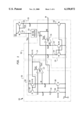
- FIG. 1 is a circuit diagram of a bandgap voltage reference circuit in accordance with an embodiment of the present invention
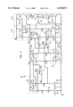
- FIG. 2 is a circuit diagram of a bandgap voltage reference circuit of FIG. 1 in accordance with an alternative embodiment of the present invention
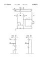
- FIG. 3 shows additional circuitry of a start-up circuit of FIG. 2 for a bandgap voltage reference circuit having low supply voltage
- FIG. 4A shows an exemplary circuit as may be employed for an operational amplifier of FIG. 1;
- FIG. 4B shows an exemplary circuit as may be employed for an operational amplifier of FIG. 1;
- FIG. 5A shows a voltage regulation circuit for a voltage V DDF of the operational amplifiers shown in FIGS. 3A and 3B;
- FIG. 5B shows an alternative voltage regulation circuit for a voltage V DDF of the operational amplifiers shown in FIGS. 3A and 3B;
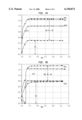
- FIG. 6A shows circuit node voltages as a function of supply voltage V DD for an exemplary bandgap voltage reference circuit of FIG. 2 having low supply voltage and operating at a temperature of 125° C.;
- FIG. 6B shows circuit node voltages as a function of supply voltage V DD for an exemplary bandgap voltage reference circuit of FIG. 2 having low supply voltage and operating at a temperature of -35° C.;
- FIG. 7A shows circuit node voltages as a function of supply voltage V DD for an exemplary bandgap voltage reference circuit of FIG. 2 having a standard supply voltage and operating at a temperature of 125° C.;
- FIG. 7B shows circuit node voltages as a function of supply voltage V DD for an exemplary bandgap voltage reference circuit of FIG. 2 having standard supply voltage and operating at a temperature of -35° C.
- bandgap voltage reference circuit 100 in accordance with one embodiment of the present invention.
- bandgap voltage reference circuit 100 comprises a current source 150 as a power supply, voltage regulator 118, first stage 190, and second stage 192.
- First stage 190 is a proportional to absolute temperature (PTAT) voltage generator driven by the current source 150.
- First stage 190 comprises a first current mirror 160 having MOS devices 102 and 104, a load resistor 110 with resistance R1, a pair of semiconductor devices shown as PNP transistors 106 and 108 having device sizes Q1 and Q2, and a first operational amplifier (VAMP1) 112.
- Second stage 192 is a current mirror and voltage buffer.
- Second stage 192 comprises a second current mirror 170 having MOS devices 114, 120 and 122, a second operational amplifier (VAMP2) 116 having feedback resistor 124 with resistance R2, and MOS device 130.
- VAMP2 second operational amplifier
- Current source 150 may be realized as a pair of MOS devices 126 and 128, for example, and as a current mirror coupled across a voltage source, such as V DD , to a regulated voltage V REG , although the scope of the invention is not limited in this respect.
- the term "operational amplifier" for VAMP1 112 and VAMP2 116 refers to a device that directly compares two voltage levels or voltage signals, and provides an amplified output voltage signal response based at least in part on the voltage signal comparison.
- VAMP1 112 compares the voltage across both load element 110 and PNP transistor 106 at node N1 with the voltage across PNP transistor 108 at node N2.
- MOS devices 102 and 104 are coupled so as to provide a first current mirror having proportional currents in first and second paths.
- current passing through a MOS device is proportional to a gate-width of the device.
- a ratio of the first current to the second current is thus determined by a ratio of the sizes of MOS devices 102 and 104.
- MOS device 104 may have a gate width approximately eight times larger than that of MOS device 102.
- a first current I1 of approximately 10 ⁇ A flows through the first current path at node N1
- a second current 12 of approximately 80 ⁇ A flows through node N2.
- MOS devices 102 and 104 have gates electrically coupled to the voltage comparison, V GATE , generated by VAMP1 112.
- the voltage V GATE provided by VAMP1 112 causes the drain-to-source voltages of MOS devices 102 and 104 to be substantially equal, and also causes MOS devices 102 and 104 to operate at or near a saturation region during circuit operation of bandgap voltage reference circuit 100.
- VAMP1 112 by operating MOS device 102 so as to provide current I1, causes voltage V R1 to appear across the load resistor 110.
- a feedback of V GATE provided by VAMP1 causes the voltages of nodes N1 and N2 to be approximately equal.
- bipolar PNP transistors 106 and 108 are coupled to the first and the second current paths through nodes N1 and N2, respectively.
- currents flowing through the first and second current paths are related to voltages of bipolar PNP transistors 106 and 108 located along the first and second current paths, respectively.
- Such relation substantially follows a diode junction equation. Nonetheless, the invention herein is not limited in scope to the use of PNP or NPN bipolar transistors and other semiconductor devices may be employed.
- semiconductor device refers herein to a device comprising semiconductor material that includes a semiconductor junction in which, for the device, a relationship between the current density, J, through the device and the voltage, V, across the device or any portion thereof approximately follows the diode junction equation (1):
- V T is the thermal voltage and equals kT/q, with k being Boltzman's constant, T being absolute temperature and q being a charge on an electron.
- V may approximately follow equation (1) due to a series resistance, current leakage or other losses in the device.
- a base-to-emitter voltage V BE across each of the pair of PNP transistors 106 and 108 is given by equation (2):
- Load resistor 110 having resistance R1 may be a combination of N+ and Ntub resistors chosen to have a composite temperature coefficient such that the resistance R1 is roughly proportional to absolute temperature over the temperature range of interest. Further, the base-to-emitter voltage V BE as given in equation (2) may also vary in proportion to absolute temperature.
- second stage 192 is employed as a voltage buffer to provide a voltage V BG derived from the voltages V R1 across load resistor 110 and the base-to-emitter voltages of PNP transistors 106 and 108 of the PTAT voltage generator.
- MOS device 120 of second current mirror 170 is diode-connected with its drain electrically coupled to its gate in order that a positive voltage applied to the gate of MOS device 120 operates the device at or near the saturation region.
- MOS device 114 Current through MOS device 102 is mirrored by MOS device 114, which may be desirably chosen with a gate width M3 double the gate width M1 of MOS device 102 so as to provide a current of, for example, 20 ⁇ A through MOS device 120.
- Current mirror 170 operates to provide an equivalent current of, for example, 20 ⁇ A through MOS device 122 since MOS devices 120 and 122 have equivalent gate widths.
- FIG. 1 a diode-connected MOS device 130 in series with MOS device 128 of current source 150.
- the current through MOS device 130 is mirrored from MOS device 120 in steady state operation of the bandgap voltage reference circuit 100. Further, current of MOS device 130 is mirrored by MOS device 128 into MOS device 126.
- VAMP2 116 Current appearing at node 3 passing through MOS device 122 also passes through feedback resistor 124 of VAMP2 116.
- the feedback path of VAMP2 116 through feedback resistor 124 drives the voltage of nodes N2 and N3 to be approximately equal.
- the voltage V BE2 which is the base-to-emitter voltage and voltage V R1 across load resistor 110, across PNP transistor 108 appears at node N2 at one input terminal of VAMP2 116.
- the voltage across the feedback resistor 124 is V R2
- the voltage appearing at the input terminal of VAMP2 116 at node N3 is approximately V BG -V R2 , which is driven to V BE2 by operation of VAMP2 116.
- the voltage V R2 across the feedback resistor 124 is proportional to the voltage V R1 across load resistor 110 by operation of the current path through MOS device 122 being proportional to the current of MOS device 102. Consequently, a variation in voltage. V BE2 and an opposite variation in voltage V R1 due to temperature is reflected in voltage V BG . Consequently, the voltage V BG is approximately constant with temperature.
- voltage V R1 across load resistor 110 is proportional to absolute temperature, or PTAT.
- An almost temperature-independent voltage V BG may thus be achieved by adding the varying base-to-emitter voltage V BE across PNP transistor 108 to the appropriately scaled varying PTAT voltage V R1 appearing across load resistor 110.
- Scaling may be accomplished by tuning a ratio of the resistance values R 1 /R 2 . Consequently, the current through load resistor 110 may be approximately independent of temperature.
- a supply current from current source 150 for the entire voltage reference 100 is mirrored through the second stage 192 from the current through load resistor 110, a total current consumption of the voltage reference 100 may remain nearly constant with temperature.
- the value R1 of composite resistance of load resistor 110 is chosen such that, for the desired voltage V BG , the current I1 through PNP transistor 106 is 10 mA and the current 12 through PNP transistor 108 is 80 mA.
- the resulting bandgap voltage V BG which may be near 1.24 volts, is tuned empirically by adjusting the ratio of resistance values R1/R2 of load resistor 110 and feedback resistor 124 for optimal temperature-dependent behavior over various processing and operating conditions.
- FIG. 2 shows a bandgap voltage reference circuit 200 in accordance with an alternative embodiment of the present invention including voltage regulator 118, current bias reference 202, resistor-divider load 207, and start-up circuit 201. Operation in accordance with the present invention for the bandgap voltage reference circuit 200 is now described, and devices of FIG. 2 having the same reference numerals as devices shown in FIG. 1 operate in a manner similar to those devices described with reference to FIG. 1.
- Resistor-divider load 207 having resistors 208 and 209 may be coupled between node N4 at voltage V BG and the common node voltage V SS to generate output voltages below, for example, 1.24 volts since the bandgap voltage V BG is buffered by VAMP2 116.
- a regulated supply voltage V REG is generally employed.
- Bandgap reference circuit 100 in accordance with the present invention may not have adequate headroom. Consequently, a modified voltage regulation method of V REG is employed for which the operational amplifiers VAMP1 112 and VAMP2 116 are connected directly to supply voltage V DD .
- the simplest configuration for such voltage regulation may be to couple the output voltage V BG of VAMP2 directly to V REG .
- better performance may be achieved by employing one or more devices coupled between V BG and V REG .
- voltage regulator 118 of FIG. 1 may be implemented by using two MOS devices 204 and 206. Better performance may be achieved with the use of either, or both, MOS devices 204 and 206.
- MOS device 206 is desirably a standard-threshold, diode-connected N-channel device causing V REG to be regulated at a voltage well above V BG , thus making the operating points of MOS devices 102, 104 and 114 less sensitive to temperature variation since nodes N1 and N2 rise in voltage as temperature drops.
- MOS device 206 is desirably employed for a standard supply voltage V DD of, for example, 2.4 volts.
- MOS device 204 is desirably a low-threshold, diode-connected, N-channel device and is desirably employed for a low supply voltage V DD such as 1.8 volts.
- V DD low supply voltage
- MOS device 204 When the temperature is high, the voltage at node N2 is low enough to turn on MOS device 204, and the voltage V REG is just slightly above V BG .
- V REG is just slightly above V BG .
- This temperature-dependent voltage regulation of MOS device 204 improves the DC power supply rejection while permitting useful operation at supply voltages down to approximately 1.4 volts.
- FIG. 2 also shows current bias reference 202 having MOS device 203 that mirrors the current through MOS device 102 so as to supply a current bias reference I REF proportional to the current through MOS device 102. Because the current through MOS device 102, and hence I REF , is nearly constant with temperature, current bias reference 202 eliminates the need for a separate current reference generator as is typically required by bandgap voltage reference circuits of the prior art.
- bandgap voltage reference circuit 100 has multiple feedback loops, more than one stable state of operation may be possible for the circuit shown in FIG. 1. Consequently, start-up circuit 201 as shown in FIG. 2 may be employed to cause the bandgap voltage reference circuit 100 to start-up and remain in the desired mode of operation.
- MOS devices 246, 250, 260, and 244 are employed to power-up or power-down voltage bandgap reference circuit 100.
- Bandgap voltage reference circuit 100 is in an active state when the input voltage at node PUP is high (at voltage potential V DD ) and an input voltage at node PD is low (at potential V SS ). In the active state, MOS devices 250 and 260 are conducting ("on") while devices 246 and 244 are not conducting ("off").
- Start-up circuit 201 includes MOS devices 248, 258, 252, 254 and 256. Without a start-up circuit such as start-up circuit 201, bandgap voltage reference circuit 100 normally has at least two stable states at power-up: 1) a zero-output voltage state and 2) a desired operating state. Start-up circuit 201 operates as follows at power-up. Initially no current flows in bandgap reference circuit 100 except in start-up circuit 201, so voltages V REG , and V GATE , and VKS and the voltage at node KS, are close to the common node voltage V SS . Consequently, MOS device 248 is on, while MOS devices 258, 252, 254, and 256 are off.
- MOS device 248 charges the gate at node KS until MOS device 258 begins to conduct.
- Current flowing through MOS device 258 also flows through MOS device 128 (being in series), and current flowing through MOS device 126 is mirrored from MOS device 128 to provide power to the remainder of the circuit, causing V REG , V GATE , and the voltage VKS to rise.
- MOS devices 252, 254, and 256 begin to turn on, while falling voltage at node KS on the gate of MOS device 258 reduces the current flow through MOS device 258.
- the voltage at node KS continues to drop until MOS device 258 is turned off, and the bandgap voltage reference circuit becomes self-regulating.
- the combination of devices may insure a robust start-up process under a wide variety of start-up conditions.
- MOS device 258 is turned on initially to generate a bias current for VAMP1 112, VAMP2 116, and the bipolar PNP transistors 106 and 108.
- Start up circuit 201 may constrain V BG to be a non-zero value, and may require V GATE of VAMP1 112 to be within a predetermined range.
- the predetermined range may be such that at least some bias current exists for MOS devices 102, 104, 114, 120 and 122 and such that current drawn from the regulated supply V REG is not excessive.
- the gate of MOS device 252 voltage VKS is desirably connected to the supply voltage V REG .
- Start-up circuit 201 of FIG. 2 is a preferred embodiment for bandgap voltage reference circuit 100 having a standard voltage supply V DD of, for example, 2.4 volts.
- FIG. 3 illustrates circuit 301 that may be used in addition to start-up circuit 201 in accordance with the present invention.
- Circuit 301 may be preferred for a bandgap voltage reference circuit 200 providing V BG but having low supply voltage V DD (e.g. on the order of 1.8 volts or less).
- the gate of MOS device 252 of FIG. 2 is coupled to circuit 301 to receive the voltage VKS and not coupled directly to the regulated supply voltage V REG .
- the circuit of FIG. 3 is employed to generate adequate gate voltage on MOS device 252 of FIG. 2.
- the higher gain that is provided by the start-up circuit 201 shown in FIG. 3 may cause circuit oscillations for V DD ⁇ 1.0 volt under some processing and temperature conditions, but bandgap voltage reference circuit 100 stabilizes before V DD reaches a useful operating range.
- FIGS. 4A and 4B show embodiments of the operational amplifiers as may be used for VAMP1 112 and VAMP2 116 of the bandgap voltage reference circuit 100 of FIG. 1.
- Operational amplifier VAMP2 is similar to operational amplifier VAMP1, but device sizes of VAMP2 may be selected as being larger than those of VAMP1 since VAMP2 desirably drives a larger output load.
- the operational amplifiers of FIGS. 3A and 3B preferred for a low supply voltage V DD of, for example, 1.8 volts may include low threshold input semiconductor devices. For a standard supply voltage of 2.4 volts, the operational amplifiers may employ standard threshold semiconductor devices.
- FIG. 4A and FIG. 4B are exemplary only. As would be apparent to one skilled in the art, a variety of operational amplifier architectures may be employed in accordance with the present invention.
- a voltage regulation circuit for the voltage V DDF for the operational amplifiers of FIG. 4A and FIG. 4B may be provided as shown in FIG. 5A.
- An alternative embodiment for the bias generator of V DDF for the operational amplifier of FIG. 3A is shown in FIG. 5B and may have better temperature performance.
- the temperature dependence of the bandgap voltage increases slightly compared to the circuit of FIG. 5B, in which VDDF is connected to VDD through an R-C filter.
- PSRR may be significantly improved with a filter capacitor external to the bandgap voltage reference circuit 100.
- FIGS. 6A, 6B, 7A, and 7B are simulation results illustrating an effect of varying supply voltage V DD for the circuit designed to operate with low and standard supply voltages.
- the voltage bandgap reference circuit 200 with low supply voltage V DD has relatively stable voltage V BG for supply voltages greater than 1.5 Volts.
- the voltage bandgap reference circuit 200 with standard supply voltage V DD has relatively stable voltage V BG for supply voltages greater than 1.5 Volts.
- FIGS. 6A and 6B illustrate various circuit node voltages for the exemplary embodiment of the bandgap reference voltage circuit 200 as shown in FIG. 2 designed for a low supply voltage V DD of 1.8 volts.
- circuit node voltages are shown as a function of supply voltage V DD for the circuit operating at a temperature of 125° C.
- circuit node voltages are shown as a function of supply voltage V DD for the circuit operating at a temperature of -35° C.
- the supply voltage V DD is varied from 1.0 volt to 4.0 volts
- the voltage V DS is the voltage across the drain and source of MOS devices 102 and 104
- the voltage V CE is the voltage across the collector and emitter of PNP transistor 108.
- FIGS. 7A and 7B illustrate various circuit node voltages for bandgap reference voltage circuit 200 of FIG. 2 designed for a standard supply voltage V DD of 2.4 volts.
- circuit node voltages are shown as a function of supply voltage V DD for the circuit operating at a temperature of 125° C.
- circuit node voltages are shown as a function of supply voltage V DD for the circuit operating at a temperature of -35° C.
- the supply voltage V DD is varied from 1.0 to 4.0 volts
- the voltage V DS is the voltage across the drain and source of MOS devices 102 and 104
- the voltage V CE is the voltage across the collector and emitter of PNP transistor 108.
Abstract
Description
J=J.sub.o (e.sup.V/V.sub.T -1) (1)
V.sub.BE =V.sub.BEo +V.sub.T ln(J/Jo) (2)
Claims (23)
Priority Applications (2)
| Application Number | Priority Date | Filing Date | Title |
|---|---|---|---|
| US09/141,910 US6150872A (en) | 1998-08-28 | 1998-08-28 | CMOS bandgap voltage reference |
| JP23908199A JP3420536B2 (en) | 1998-08-28 | 1999-08-26 | CMOS bandgap voltage reference |
Applications Claiming Priority (1)
| Application Number | Priority Date | Filing Date | Title |
|---|---|---|---|
| US09/141,910 US6150872A (en) | 1998-08-28 | 1998-08-28 | CMOS bandgap voltage reference |
Publications (1)
| Publication Number | Publication Date |
|---|---|
| US6150872A true US6150872A (en) | 2000-11-21 |
Family
ID=22497768
Family Applications (1)
| Application Number | Title | Priority Date | Filing Date |
|---|---|---|---|
| US09/141,910 Expired - Lifetime US6150872A (en) | 1998-08-28 | 1998-08-28 | CMOS bandgap voltage reference |
Country Status (2)
| Country | Link |
|---|---|
| US (1) | US6150872A (en) |
| JP (1) | JP3420536B2 (en) |
Cited By (76)
| Publication number | Priority date | Publication date | Assignee | Title |
|---|---|---|---|---|
| US6281743B1 (en) * | 1997-09-10 | 2001-08-28 | Intel Corporation | Low supply voltage sub-bandgap reference circuit |
| US6346848B1 (en) * | 2000-06-29 | 2002-02-12 | International Business Machines Corporation | Apparatus and method for generating current linearly dependent on temperature |
| US6359425B1 (en) * | 1999-12-13 | 2002-03-19 | Zilog, Inc. | Current regulator with low voltage detection capability |
| US6407638B1 (en) * | 1999-11-15 | 2002-06-18 | Stmicroelectronics S.A. | Low temperature-corrected voltage generator device |
| US6407622B1 (en) * | 2001-03-13 | 2002-06-18 | Ion E. Opris | Low-voltage bandgap reference circuit |
| US6433621B1 (en) * | 2001-04-09 | 2002-08-13 | National Semiconductor Corporation | Bias current source with high power supply rejection |
| US6465997B2 (en) * | 2000-09-15 | 2002-10-15 | Stmicroelectronics S.A. | Regulated voltage generator for integrated circuit |
| US6501254B2 (en) * | 2001-08-27 | 2002-12-31 | Analog Devices, Inc. | Voltage source |
| US6509726B1 (en) * | 2001-07-30 | 2003-01-21 | Intel Corporation | Amplifier for a bandgap reference circuit having a built-in startup circuit |
| US20030137287A1 (en) * | 2001-12-20 | 2003-07-24 | Marie Herve Jean Francois | Performance reference voltage generator |
| US6605988B1 (en) * | 2002-02-19 | 2003-08-12 | Sun Microsystems, Inc. | Low voltage temperature-independent and temperature-dependent voltage generator |
| US20030151451A1 (en) * | 2002-02-14 | 2003-08-14 | Ko Takemura | Constant voltage generating circuit |
| US6624702B1 (en) | 2002-04-05 | 2003-09-23 | Rf Micro Devices, Inc. | Automatic Vcc control for optimum power amplifier efficiency |
| US6630859B1 (en) | 2002-01-24 | 2003-10-07 | Taiwan Semiconductor Manufacturing Company | Low voltage supply band gap circuit at low power process |
| US6661713B1 (en) | 2002-07-25 | 2003-12-09 | Taiwan Semiconductor Manufacturing Company | Bandgap reference circuit |
| US20040041551A1 (en) * | 2002-09-03 | 2004-03-04 | Mottola Michael J. | Bootstrap reference circuit including a peaking current source |
| US20040051581A1 (en) * | 2002-08-28 | 2004-03-18 | Nec Electronics Corporation | Band gap circuit |
| US20040072554A1 (en) * | 2002-10-15 | 2004-04-15 | Triquint Semiconductor, Inc. | Automatic-bias amplifier circuit |
| US6727745B2 (en) * | 2000-08-23 | 2004-04-27 | Intersil Americas Inc. | Integrated circuit with current sense circuit and associated methods |
| US6747507B1 (en) * | 2002-12-03 | 2004-06-08 | Texas Instruments Incorporated | Bias generator with improved stability for self biased phase locked loop |
| US6768371B1 (en) | 2003-03-20 | 2004-07-27 | Ami Semiconductor, Inc. | Stable floating gate voltage reference using interconnected current-to-voltage and voltage-to-current converters |
| US20040150381A1 (en) * | 2003-02-05 | 2004-08-05 | Douglas Blaine Butler | Bandgap reference circuit |
| US20040150464A1 (en) * | 2003-01-30 | 2004-08-05 | Sandisk Corporation | Voltage buffer for capacitive loads |
| US6775638B2 (en) * | 2002-04-24 | 2004-08-10 | Sun Microsystems, Inc. | Post-silicon control of an embedded temperature sensor |
| US20040166803A1 (en) * | 1999-10-21 | 2004-08-26 | Shervin Moloudi | Adaptive radio transceiver with a power amplifier |
| US20040245977A1 (en) * | 2003-06-09 | 2004-12-09 | Tran Hieu Van | Curved fractional cmos bandgap reference |
| US20040257150A1 (en) * | 2003-06-20 | 2004-12-23 | Farooqui Arshad Suhail | Bandgap reference voltage generator |
| US20050001605A1 (en) * | 2003-07-03 | 2005-01-06 | Analog Devices, Inc. | CMOS bandgap current and voltage generator |
| US6900689B2 (en) * | 2001-03-08 | 2005-05-31 | Nec Electronics Corporation | CMOS reference voltage circuit |
| US20050140428A1 (en) * | 2003-12-29 | 2005-06-30 | Tran Hieu V. | Low voltage cmos bandgap reference |
| US20050184718A1 (en) * | 2002-07-23 | 2005-08-25 | Eckhard Brass | Bandgap reference circuit |
| US20050237087A1 (en) * | 2004-04-27 | 2005-10-27 | Dake Luthuli E | Low voltage current monitoring circuit |
| US6989712B2 (en) | 2002-11-06 | 2006-01-24 | Triquint Semiconductor, Inc. | Accurate power detection for a multi-stage amplifier |
| US7030598B1 (en) * | 2003-08-06 | 2006-04-18 | National Semiconductor Corporation | Low dropout voltage regulator |
| US20060151633A1 (en) * | 2005-01-12 | 2006-07-13 | Presz Walter M Jr | Fluid nozzle system using self-propelling toroidal vortices for long-range jet impact |
| US20060202741A1 (en) * | 2005-03-14 | 2006-09-14 | Tran Hieu V | Fast start charge pump for voltage regulators |
| US20060202668A1 (en) * | 2005-03-14 | 2006-09-14 | Tran Hieu V | Fast voltage regulators for charge pumps |
| US7116088B2 (en) | 2003-06-09 | 2006-10-03 | Silicon Storage Technology, Inc. | High voltage shunt regulator for flash memory |
| US7177370B2 (en) | 2003-12-17 | 2007-02-13 | Triquint Semiconductor, Inc. | Method and architecture for dual-mode linear and saturated power amplifier operation |
| US20070164812A1 (en) * | 2006-01-17 | 2007-07-19 | Rao T V Chanakya | High voltage tolerant bias circuit with low voltage transistors |
| US20070194770A1 (en) * | 2006-02-17 | 2007-08-23 | Vignesh Kalyanaraman | Low voltage bandgap reference circuit and method |
| US20070257655A1 (en) * | 2006-05-08 | 2007-11-08 | Exar Corporation | Variable sub-bandgap reference voltage generator |
| US20080067996A1 (en) * | 2006-09-15 | 2008-03-20 | Oki Electric Industry Co., Ltd. | Reference current generator adjustable by a variable current source |
| US20080094130A1 (en) * | 2006-10-19 | 2008-04-24 | Faraday Technology Corporation | Supply-independent biasing circuit |
| US7383149B1 (en) | 2006-04-19 | 2008-06-03 | Darryl Walker | Semiconductor device having variable parameter selection based on temperature and test method |
| US7400187B1 (en) * | 2001-10-02 | 2008-07-15 | National Semiconductor Corporation | Low voltage, low Z, band-gap reference |
| US20080224682A1 (en) * | 2006-10-06 | 2008-09-18 | Holger Haiplik | Voltage reference circuit |
| US7480588B1 (en) | 2006-04-19 | 2009-01-20 | Darryl Walker | Semiconductor device having variable parameter selection based on temperature and test method |
| US7505742B2 (en) | 1997-04-25 | 2009-03-17 | Triquint Semiconductor, Inc. | Battery life extending technique for mobile wireless applications using bias level control |
| US20090079403A1 (en) * | 2007-09-26 | 2009-03-26 | Jun Xu | Apparatus to provide a current reference |
| US20090153125A1 (en) * | 2007-12-13 | 2009-06-18 | Kenji Arai | Electronic circuit |
| US20090295440A1 (en) * | 2008-06-03 | 2009-12-03 | Texas Instruments Incorporated | Systems and Methods for Cancelling Phase-Locked Loop Supply Noise |
| US20100045367A1 (en) * | 2008-08-20 | 2010-02-25 | Sanyo Electric Co., Ltd. | Low-voltage operation constant-voltage circuit |
| US20100073032A1 (en) * | 2008-09-19 | 2010-03-25 | Seiko Epson Corporation | Voltage comparator and electronic device |
| US20100085115A1 (en) * | 2008-10-03 | 2010-04-08 | Cambridge Semiconductor Limit St Andrews House St. Andrews Road | Signal generator |
| US20100164466A1 (en) * | 2008-12-29 | 2010-07-01 | Eun Sang Jo | Reference Voltage Generation Circuit |
| US7755419B2 (en) | 2006-01-17 | 2010-07-13 | Cypress Semiconductor Corporation | Low power beta multiplier start-up circuit and method |
| US20110037451A1 (en) * | 2009-08-14 | 2011-02-17 | Fujitsu Semiconductor Limited | Bandgap voltage reference circuit |
| US20110199069A1 (en) * | 2010-02-17 | 2011-08-18 | Austriamicrosystems Ag | Band Gap Reference Circuit |
| US8598862B2 (en) | 2011-03-07 | 2013-12-03 | Dialog Semiconductor Gmbh. | Startup circuit for low voltage cascode beta multiplier current generator |
| US20140077791A1 (en) * | 2012-09-14 | 2014-03-20 | Nxp B.V. | Low power fast settling voltage reference circuit |
| CN103677055A (en) * | 2012-09-24 | 2014-03-26 | 联咏科技股份有限公司 | Band gap reference circuit and double-output self-reference voltage stabilizer thereof |
| US20150084117A1 (en) * | 2009-06-17 | 2015-03-26 | Madhur Bobde | Bottom source nmos triggered zener clamp for configuring an ultra-low voltage transient voltage suppressor (tvs) |
| US20150276501A1 (en) * | 2014-03-28 | 2015-10-01 | Darryl G. Walker | Power up of semiconductor device having a temperature circuit and method therefor |
| CN105094200A (en) * | 2015-08-14 | 2015-11-25 | 灿芯半导体(上海)有限公司 | Current source circuit |
| US20160062385A1 (en) * | 2014-09-02 | 2016-03-03 | Infineon Technologies Ag | Generating a current with inverse supply voltage proportionality |
| US9286991B1 (en) | 2015-02-17 | 2016-03-15 | Darryl G. Walker | Multi-chip non-volatile semiconductor memory package including heater and sensor elements |
| US20160357213A1 (en) * | 2011-05-17 | 2016-12-08 | Stmicroelectronics (Rousset) Sas | Method and Device for Generating an Adjustable Bandgap Reference Voltage |
| US9645191B2 (en) | 2014-08-20 | 2017-05-09 | Darryl G. Walker | Testing and setting performance parameters in a semiconductor device and method therefor |
| US9667134B2 (en) * | 2015-09-15 | 2017-05-30 | Texas Instruments Deutschland Gmbh | Startup circuit for reference circuits |
| CN109116904A (en) * | 2018-09-25 | 2019-01-01 | 聚辰半导体(上海)有限公司 | A kind of biasing circuit |
| CN109743047A (en) * | 2018-12-29 | 2019-05-10 | 长江存储科技有限责任公司 | A kind of signal generating circuit |
| US10359799B2 (en) | 2017-09-12 | 2019-07-23 | Samsung Electronics Co., Ltd. | Bandgap reference voltage generation circuit and bandgap reference voltage generation system |
| US10423188B1 (en) * | 2018-04-10 | 2019-09-24 | Faraday Technology Corp. | Voltage generating circuit for improving stability of bandgap voltage generator |
| CN113050738A (en) * | 2019-12-27 | 2021-06-29 | 安特(苏州)半导体有限公司 | CMOS band-gap reference source circuit |
| US20220413532A1 (en) * | 2021-06-23 | 2022-12-29 | Nxp B.V. | Low dropout regulator |
Families Citing this family (5)
| Publication number | Priority date | Publication date | Assignee | Title |
|---|---|---|---|---|
| US6737852B2 (en) | 2001-10-25 | 2004-05-18 | Advantest Corporation | Clock skew measuring apparatus and method |
| JP4808069B2 (en) | 2006-05-01 | 2011-11-02 | 富士通セミコンダクター株式会社 | Reference voltage generator |
| JP2008305150A (en) * | 2007-06-07 | 2008-12-18 | Nec Electronics Corp | Bandgap circuit |
| KR101053259B1 (en) * | 2008-12-01 | 2011-08-02 | (주)에프씨아이 | Low-Noise Voltage Reference Circuit for Improving Frequency Fluctuation of Ring Oscillator |
| CN101859160B (en) * | 2010-06-17 | 2012-05-30 | 复旦大学 | Band-gap reference source of ultra-low power supply voltage |
Citations (10)
| Publication number | Priority date | Publication date | Assignee | Title |
|---|---|---|---|---|
| US4317054A (en) * | 1980-02-07 | 1982-02-23 | Mostek Corporation | Bandgap voltage reference employing sub-surface current using a standard CMOS process |
| US4399399A (en) * | 1981-12-21 | 1983-08-16 | Motorola, Inc. | Precision current source |
| US4622512A (en) * | 1985-02-11 | 1986-11-11 | Analog Devices, Inc. | Band-gap reference circuit for use with CMOS IC chips |
| US4931718A (en) * | 1988-09-26 | 1990-06-05 | Siemens Aktiengesellschaft | CMOS voltage reference |
| US5061862A (en) * | 1989-07-11 | 1991-10-29 | Nec Corporation | Reference voltage generating circuit |
| US5512817A (en) * | 1993-12-29 | 1996-04-30 | At&T Corp. | Bandgap voltage reference generator |
| US5646518A (en) * | 1994-11-18 | 1997-07-08 | Lucent Technologies Inc. | PTAT current source |
| US5666046A (en) * | 1995-08-24 | 1997-09-09 | Motorola, Inc. | Reference voltage circuit having a substantially zero temperature coefficient |
| US5867013A (en) * | 1997-11-20 | 1999-02-02 | Cypress Semiconductor Corporation | Startup circuit for band-gap reference circuit |
| US5900773A (en) * | 1997-04-22 | 1999-05-04 | Microchip Technology Incorporated | Precision bandgap reference circuit |
-
1998
- 1998-08-28 US US09/141,910 patent/US6150872A/en not_active Expired - Lifetime
-
1999
- 1999-08-26 JP JP23908199A patent/JP3420536B2/en not_active Expired - Fee Related
Patent Citations (10)
| Publication number | Priority date | Publication date | Assignee | Title |
|---|---|---|---|---|
| US4317054A (en) * | 1980-02-07 | 1982-02-23 | Mostek Corporation | Bandgap voltage reference employing sub-surface current using a standard CMOS process |
| US4399399A (en) * | 1981-12-21 | 1983-08-16 | Motorola, Inc. | Precision current source |
| US4622512A (en) * | 1985-02-11 | 1986-11-11 | Analog Devices, Inc. | Band-gap reference circuit for use with CMOS IC chips |
| US4931718A (en) * | 1988-09-26 | 1990-06-05 | Siemens Aktiengesellschaft | CMOS voltage reference |
| US5061862A (en) * | 1989-07-11 | 1991-10-29 | Nec Corporation | Reference voltage generating circuit |
| US5512817A (en) * | 1993-12-29 | 1996-04-30 | At&T Corp. | Bandgap voltage reference generator |
| US5646518A (en) * | 1994-11-18 | 1997-07-08 | Lucent Technologies Inc. | PTAT current source |
| US5666046A (en) * | 1995-08-24 | 1997-09-09 | Motorola, Inc. | Reference voltage circuit having a substantially zero temperature coefficient |
| US5900773A (en) * | 1997-04-22 | 1999-05-04 | Microchip Technology Incorporated | Precision bandgap reference circuit |
| US5867013A (en) * | 1997-11-20 | 1999-02-02 | Cypress Semiconductor Corporation | Startup circuit for band-gap reference circuit |
Cited By (166)
| Publication number | Priority date | Publication date | Assignee | Title |
|---|---|---|---|---|
| US7505742B2 (en) | 1997-04-25 | 2009-03-17 | Triquint Semiconductor, Inc. | Battery life extending technique for mobile wireless applications using bias level control |
| US6281743B1 (en) * | 1997-09-10 | 2001-08-28 | Intel Corporation | Low supply voltage sub-bandgap reference circuit |
| US7860454B2 (en) * | 1999-10-21 | 2010-12-28 | Broadcom Corporation | Adaptive radio transceiver with a power amplifier |
| US8014719B2 (en) | 1999-10-21 | 2011-09-06 | Broadcom Corporation | Adaptive radio transceiver with a power amplifier |
| US20040166803A1 (en) * | 1999-10-21 | 2004-08-26 | Shervin Moloudi | Adaptive radio transceiver with a power amplifier |
| US20040166804A1 (en) * | 1999-10-21 | 2004-08-26 | Shervin Moloudi | Adaptive radio transceiver with a power amplifier |
| US6407638B1 (en) * | 1999-11-15 | 2002-06-18 | Stmicroelectronics S.A. | Low temperature-corrected voltage generator device |
| US6359425B1 (en) * | 1999-12-13 | 2002-03-19 | Zilog, Inc. | Current regulator with low voltage detection capability |
| US6346848B1 (en) * | 2000-06-29 | 2002-02-12 | International Business Machines Corporation | Apparatus and method for generating current linearly dependent on temperature |
| US6727745B2 (en) * | 2000-08-23 | 2004-04-27 | Intersil Americas Inc. | Integrated circuit with current sense circuit and associated methods |
| US6465997B2 (en) * | 2000-09-15 | 2002-10-15 | Stmicroelectronics S.A. | Regulated voltage generator for integrated circuit |
| US7173481B2 (en) * | 2001-03-08 | 2007-02-06 | Nec Electronics Corporation | CMOS reference voltage circuit |
| US6900689B2 (en) * | 2001-03-08 | 2005-05-31 | Nec Electronics Corporation | CMOS reference voltage circuit |
| US20050134365A1 (en) * | 2001-03-08 | 2005-06-23 | Katsuji Kimura | CMOS reference voltage circuit |
| US6407622B1 (en) * | 2001-03-13 | 2002-06-18 | Ion E. Opris | Low-voltage bandgap reference circuit |
| US6433621B1 (en) * | 2001-04-09 | 2002-08-13 | National Semiconductor Corporation | Bias current source with high power supply rejection |
| US6509726B1 (en) * | 2001-07-30 | 2003-01-21 | Intel Corporation | Amplifier for a bandgap reference circuit having a built-in startup circuit |
| US6501254B2 (en) * | 2001-08-27 | 2002-12-31 | Analog Devices, Inc. | Voltage source |
| US7400187B1 (en) * | 2001-10-02 | 2008-07-15 | National Semiconductor Corporation | Low voltage, low Z, band-gap reference |
| US6683444B2 (en) * | 2001-12-20 | 2004-01-27 | Koninklijke Philips Electronics N.V. | Performance reference voltage generator |
| US20030137287A1 (en) * | 2001-12-20 | 2003-07-24 | Marie Herve Jean Francois | Performance reference voltage generator |
| US6630859B1 (en) | 2002-01-24 | 2003-10-07 | Taiwan Semiconductor Manufacturing Company | Low voltage supply band gap circuit at low power process |
| US20030151451A1 (en) * | 2002-02-14 | 2003-08-14 | Ko Takemura | Constant voltage generating circuit |
| US6784724B2 (en) * | 2002-02-14 | 2004-08-31 | Rohm Co., Ltd. | Constant voltage generating circuit |
| US6605988B1 (en) * | 2002-02-19 | 2003-08-12 | Sun Microsystems, Inc. | Low voltage temperature-independent and temperature-dependent voltage generator |
| US6624702B1 (en) | 2002-04-05 | 2003-09-23 | Rf Micro Devices, Inc. | Automatic Vcc control for optimum power amplifier efficiency |
| US6775638B2 (en) * | 2002-04-24 | 2004-08-10 | Sun Microsystems, Inc. | Post-silicon control of an embedded temperature sensor |
| US6972549B2 (en) * | 2002-07-23 | 2005-12-06 | Infineon Technologies Ag | Bandgap reference circuit |
| US20050184718A1 (en) * | 2002-07-23 | 2005-08-25 | Eckhard Brass | Bandgap reference circuit |
| US6661713B1 (en) | 2002-07-25 | 2003-12-09 | Taiwan Semiconductor Manufacturing Company | Bandgap reference circuit |
| US7098729B2 (en) * | 2002-08-28 | 2006-08-29 | Nec Electronicss Corporation | Band gap circuit |
| US20040051581A1 (en) * | 2002-08-28 | 2004-03-18 | Nec Electronics Corporation | Band gap circuit |
| US6737908B2 (en) | 2002-09-03 | 2004-05-18 | Micrel, Inc. | Bootstrap reference circuit including a shunt bandgap regulator with external start-up current source |
| US20040041551A1 (en) * | 2002-09-03 | 2004-03-04 | Mottola Michael J. | Bootstrap reference circuit including a peaking current source |
| US20040072554A1 (en) * | 2002-10-15 | 2004-04-15 | Triquint Semiconductor, Inc. | Automatic-bias amplifier circuit |
| US7010284B2 (en) | 2002-11-06 | 2006-03-07 | Triquint Semiconductor, Inc. | Wireless communications device including power detector circuit coupled to sample signal at interior node of amplifier |
| US6989712B2 (en) | 2002-11-06 | 2006-01-24 | Triquint Semiconductor, Inc. | Accurate power detection for a multi-stage amplifier |
| US6747507B1 (en) * | 2002-12-03 | 2004-06-08 | Texas Instruments Incorporated | Bias generator with improved stability for self biased phase locked loop |
| US20060007726A1 (en) * | 2003-01-30 | 2006-01-12 | Shahzad Khalid | Voltage buffer for capacitive loads |
| US7471139B2 (en) | 2003-01-30 | 2008-12-30 | Sandisk Corporation | Voltage buffer for capacitive loads |
| US7002401B2 (en) * | 2003-01-30 | 2006-02-21 | Sandisk Corporation | Voltage buffer for capacitive loads |
| US20070103227A1 (en) * | 2003-01-30 | 2007-05-10 | Shahzad Khalid | Voltage Buffer for Capacitive Loads |
| US7167041B2 (en) | 2003-01-30 | 2007-01-23 | Sandisk Corporation | Voltage buffer for capacitive loads |
| US20040150464A1 (en) * | 2003-01-30 | 2004-08-05 | Sandisk Corporation | Voltage buffer for capacitive loads |
| US20040150381A1 (en) * | 2003-02-05 | 2004-08-05 | Douglas Blaine Butler | Bandgap reference circuit |
| US6815941B2 (en) | 2003-02-05 | 2004-11-09 | United Memories, Inc. | Bandgap reference circuit |
| US6768371B1 (en) | 2003-03-20 | 2004-07-27 | Ami Semiconductor, Inc. | Stable floating gate voltage reference using interconnected current-to-voltage and voltage-to-current converters |
| US6841982B2 (en) * | 2003-06-09 | 2005-01-11 | Silicon Storage Technology, Inc. | Curved fractional CMOS bandgap reference |
| US20040245977A1 (en) * | 2003-06-09 | 2004-12-09 | Tran Hieu Van | Curved fractional cmos bandgap reference |
| US7116088B2 (en) | 2003-06-09 | 2006-10-03 | Silicon Storage Technology, Inc. | High voltage shunt regulator for flash memory |
| US7233196B2 (en) | 2003-06-20 | 2007-06-19 | Sires Labs Sdn. Bhd. | Bandgap reference voltage generator |
| US20040257150A1 (en) * | 2003-06-20 | 2004-12-23 | Farooqui Arshad Suhail | Bandgap reference voltage generator |
| US7088085B2 (en) * | 2003-07-03 | 2006-08-08 | Analog-Devices, Inc. | CMOS bandgap current and voltage generator |
| US20050001605A1 (en) * | 2003-07-03 | 2005-01-06 | Analog Devices, Inc. | CMOS bandgap current and voltage generator |
| US7030598B1 (en) * | 2003-08-06 | 2006-04-18 | National Semiconductor Corporation | Low dropout voltage regulator |
| US7177370B2 (en) | 2003-12-17 | 2007-02-13 | Triquint Semiconductor, Inc. | Method and architecture for dual-mode linear and saturated power amplifier operation |
| US6943617B2 (en) | 2003-12-29 | 2005-09-13 | Silicon Storage Technology, Inc. | Low voltage CMOS bandgap reference |
| US20050140428A1 (en) * | 2003-12-29 | 2005-06-30 | Tran Hieu V. | Low voltage cmos bandgap reference |
| US20050237087A1 (en) * | 2004-04-27 | 2005-10-27 | Dake Luthuli E | Low voltage current monitoring circuit |
| US6992523B2 (en) * | 2004-04-27 | 2006-01-31 | Texas Instruments Incorporated | Low voltage current monitoring circuit |
| US20060151633A1 (en) * | 2005-01-12 | 2006-07-13 | Presz Walter M Jr | Fluid nozzle system using self-propelling toroidal vortices for long-range jet impact |
| US20060202668A1 (en) * | 2005-03-14 | 2006-09-14 | Tran Hieu V | Fast voltage regulators for charge pumps |
| US20100188138A1 (en) * | 2005-03-14 | 2010-07-29 | Silicon Storage Technology, Inc. | Fast Start Charge Pump for Voltage Regulators |
| US8674749B2 (en) | 2005-03-14 | 2014-03-18 | Silicon Storage Technology, Inc. | Fast start charge pump for voltage regulators |
| US20110121799A1 (en) * | 2005-03-14 | 2011-05-26 | Silicon Storage Technology, Inc. | Fast Voltage Regulators For Charge Pumps |
| US7728563B2 (en) | 2005-03-14 | 2010-06-01 | Silicon Storage Technology, Inc. | Fast voltage regulators for charge pumps |
| US7868604B2 (en) | 2005-03-14 | 2011-01-11 | Silicon Storage Technology, Inc. | Fast voltage regulators for charge pumps |
| US8067931B2 (en) | 2005-03-14 | 2011-11-29 | Silicon Storage Technology, Inc. | Fast voltage regulators for charge pumps |
| US8497667B2 (en) | 2005-03-14 | 2013-07-30 | Silicon Storage Technology, Inc. | Fast voltage regulators for charge pumps |
| US20090160411A1 (en) * | 2005-03-14 | 2009-06-25 | Silicon Storage Technology, Inc. | Fast voltage regulators for charge pumps |
| US20060202741A1 (en) * | 2005-03-14 | 2006-09-14 | Tran Hieu V | Fast start charge pump for voltage regulators |
| US7362084B2 (en) * | 2005-03-14 | 2008-04-22 | Silicon Storage Technology, Inc. | Fast voltage regulators for charge pumps |
| US7737765B2 (en) | 2005-03-14 | 2010-06-15 | Silicon Storage Technology, Inc. | Fast start charge pump for voltage regulators |
| US7755419B2 (en) | 2006-01-17 | 2010-07-13 | Cypress Semiconductor Corporation | Low power beta multiplier start-up circuit and method |
| US7830200B2 (en) * | 2006-01-17 | 2010-11-09 | Cypress Semiconductor Corporation | High voltage tolerant bias circuit with low voltage transistors |
| US20070164812A1 (en) * | 2006-01-17 | 2007-07-19 | Rao T V Chanakya | High voltage tolerant bias circuit with low voltage transistors |
| US7728574B2 (en) | 2006-02-17 | 2010-06-01 | Micron Technology, Inc. | Reference circuit with start-up control, generator, device, system and method including same |
| US20070194770A1 (en) * | 2006-02-17 | 2007-08-23 | Vignesh Kalyanaraman | Low voltage bandgap reference circuit and method |
| US8106644B2 (en) | 2006-02-17 | 2012-01-31 | Micron Technology, Inc. | Reference circuit with start-up control, generator, device, system and method including same |
| US20100237848A1 (en) * | 2006-02-17 | 2010-09-23 | Micron Technology, Inc. | Reference circuit with start-up control, generator, device, system and method including same |
| US8005641B2 (en) | 2006-04-19 | 2011-08-23 | Agersonn Rall Group, L.L.C. | Temperature sensing circuit with hysteresis and time delay |
| US7953573B2 (en) | 2006-04-19 | 2011-05-31 | Agersonn Rall Group, L.L.C. | Semiconductor device having variable parameter selection based on temperature and test method |
| US8040742B2 (en) | 2006-04-19 | 2011-10-18 | Agersonn Rall Group, L.L.C. | Semiconductor device having variable parameter selection based on temperature and test method |
| US7603249B1 (en) | 2006-04-19 | 2009-10-13 | Darryl Walker | Semiconductor device having variable parameter selection based on temperature and test method |
| US8081532B2 (en) | 2006-04-19 | 2011-12-20 | Intellectual Ventures Holding 83 LLC | Semiconductor device having variable parameter selection based on temperature and test method |
| US8049145B1 (en) | 2006-04-19 | 2011-11-01 | Agerson Rall Group, L.L.C. | Semiconductor device having variable parameter selection based on temperature and test method |
| US20110046912A1 (en) * | 2006-04-19 | 2011-02-24 | Walker Darryl G | Semiconductor Device having variable parameter selection based on temperature and test method |
| US7535786B1 (en) | 2006-04-19 | 2009-05-19 | Darryl Walker | Semiconductor device having variable parameter selection based on temperature and test method |
| US7760570B1 (en) | 2006-04-19 | 2010-07-20 | Darryl Walker | Semiconductor device having variable parameter selection based on temperature and test method |
| US7383149B1 (en) | 2006-04-19 | 2008-06-03 | Darryl Walker | Semiconductor device having variable parameter selection based on temperature and test method |
| US9766135B2 (en) | 2006-04-19 | 2017-09-19 | Nytell Software LLC | Semiconductor device having variable parameter selection based on temperature and test method |
| US7480588B1 (en) | 2006-04-19 | 2009-01-20 | Darryl Walker | Semiconductor device having variable parameter selection based on temperature and test method |
| US20110044118A1 (en) * | 2006-04-19 | 2011-02-24 | Walker Darryl G | Semiconductor Device having variable parameter selection based on temperature and test method |
| US10656028B2 (en) | 2006-04-19 | 2020-05-19 | Samsung Electronics Co., Ltd. | Semiconductor device having variable parameter selection based on temperature and test method |
| US8308359B2 (en) | 2006-04-19 | 2012-11-13 | Intellectual Ventures Holding 83 LLC | Semiconductor device having variable parameter selection based on temperature and test method |
| US20110037138A1 (en) * | 2006-04-19 | 2011-02-17 | Walker Darryl G | Semiconductor Device having variable parameter selection based on temperature and test method |
| US8497453B2 (en) | 2006-04-19 | 2013-07-30 | Intellectual Ventures Holding 83 LLC | Semiconductor device having variable parameter selection based on temperature |
| US20110044372A1 (en) * | 2006-04-19 | 2011-02-24 | Walker Darryl G | Semiconductor Device having variable parameter selection based on temperature and test method |
| US20110044119A1 (en) * | 2006-04-19 | 2011-02-24 | Walker Darryl G | Semiconductor Device having variable parameter selection based on temperature and test method |
| US7436245B2 (en) * | 2006-05-08 | 2008-10-14 | Exar Corporation | Variable sub-bandgap reference voltage generator |
| US20070257655A1 (en) * | 2006-05-08 | 2007-11-08 | Exar Corporation | Variable sub-bandgap reference voltage generator |
| US7737675B2 (en) | 2006-09-15 | 2010-06-15 | Oki Semiconductor Co., Ltd. | Reference current generator adjustable by a variable current source |
| US20080067996A1 (en) * | 2006-09-15 | 2008-03-20 | Oki Electric Industry Co., Ltd. | Reference current generator adjustable by a variable current source |
| US20080224682A1 (en) * | 2006-10-06 | 2008-09-18 | Holger Haiplik | Voltage reference circuit |
| US7626374B2 (en) * | 2006-10-06 | 2009-12-01 | Wolfson Microelectronics Plc | Voltage reference circuit |
| US20080094130A1 (en) * | 2006-10-19 | 2008-04-24 | Faraday Technology Corporation | Supply-independent biasing circuit |
| US20090079403A1 (en) * | 2007-09-26 | 2009-03-26 | Jun Xu | Apparatus to provide a current reference |
| US7893681B2 (en) * | 2007-12-13 | 2011-02-22 | Spansion Llc | Electronic circuit |
| US20090153125A1 (en) * | 2007-12-13 | 2009-06-18 | Kenji Arai | Electronic circuit |
| US8674753B2 (en) * | 2008-06-03 | 2014-03-18 | Texas Instruments Incorporated | Systems and methods for cancelling phase-locked loop supply noise |
| US20090295440A1 (en) * | 2008-06-03 | 2009-12-03 | Texas Instruments Incorporated | Systems and Methods for Cancelling Phase-Locked Loop Supply Noise |
| CN101685316A (en) * | 2008-08-20 | 2010-03-31 | 三洋电机株式会社 | Low-voltage operation constant-voltage circuit |
| US8207787B2 (en) * | 2008-08-20 | 2012-06-26 | Semiconductor Components Industries, Llc | Low-voltage operation constant-voltage circuit |
| US20100045367A1 (en) * | 2008-08-20 | 2010-02-25 | Sanyo Electric Co., Ltd. | Low-voltage operation constant-voltage circuit |
| CN101685316B (en) * | 2008-08-20 | 2013-11-20 | 三洋电机株式会社 | Low-voltage operation constant-voltage circuit |
| US20100073032A1 (en) * | 2008-09-19 | 2010-03-25 | Seiko Epson Corporation | Voltage comparator and electronic device |
| US8022744B2 (en) * | 2008-10-03 | 2011-09-20 | Cambridge Semiconductor Limited | Signal generator |
| US20100085115A1 (en) * | 2008-10-03 | 2010-04-08 | Cambridge Semiconductor Limit St Andrews House St. Andrews Road | Signal generator |
| US8269477B2 (en) * | 2008-12-29 | 2012-09-18 | Dongbu Hitek Co., Ltd. | Reference voltage generation circuit |
| US20100164466A1 (en) * | 2008-12-29 | 2010-07-01 | Eun Sang Jo | Reference Voltage Generation Circuit |
| US10205017B2 (en) * | 2009-06-17 | 2019-02-12 | Alpha And Omega Semiconductor Incorporated | Bottom source NMOS triggered Zener clamp for configuring an ultra-low voltage transient voltage suppressor (TVS) |
| US20150084117A1 (en) * | 2009-06-17 | 2015-03-26 | Madhur Bobde | Bottom source nmos triggered zener clamp for configuring an ultra-low voltage transient voltage suppressor (tvs) |
| US20110037451A1 (en) * | 2009-08-14 | 2011-02-17 | Fujitsu Semiconductor Limited | Bandgap voltage reference circuit |
| US8933682B2 (en) | 2009-08-14 | 2015-01-13 | Spansion Llc | Bandgap voltage reference circuit |
| US8933683B2 (en) | 2010-02-17 | 2015-01-13 | Ams Ag | Band gap reference circuit |
| US20110199069A1 (en) * | 2010-02-17 | 2011-08-18 | Austriamicrosystems Ag | Band Gap Reference Circuit |
| EP2360547A1 (en) * | 2010-02-17 | 2011-08-24 | austriamicrosystems AG | Band gap reference circuit |
| US8598862B2 (en) | 2011-03-07 | 2013-12-03 | Dialog Semiconductor Gmbh. | Startup circuit for low voltage cascode beta multiplier current generator |
| US9804631B2 (en) * | 2011-05-17 | 2017-10-31 | Stmicroelectronics (Rousset) Sas | Method and device for generating an adjustable bandgap reference voltage |
| US20160357213A1 (en) * | 2011-05-17 | 2016-12-08 | Stmicroelectronics (Rousset) Sas | Method and Device for Generating an Adjustable Bandgap Reference Voltage |
| US20140077791A1 (en) * | 2012-09-14 | 2014-03-20 | Nxp B.V. | Low power fast settling voltage reference circuit |
| US9235229B2 (en) * | 2012-09-14 | 2016-01-12 | Nxp B.V. | Low power fast settling voltage reference circuit |
| CN103677055A (en) * | 2012-09-24 | 2014-03-26 | 联咏科技股份有限公司 | Band gap reference circuit and double-output self-reference voltage stabilizer thereof |
| CN103677055B (en) * | 2012-09-24 | 2015-11-18 | 联咏科技股份有限公司 | Energy band gap reference circuit and dual output oneself parameter voltage stabilizator thereof |
| US20160169750A1 (en) * | 2014-03-28 | 2016-06-16 | Darryl G. Walker | Semiconductor device having temperature sensor circuits |
| US9939330B2 (en) | 2014-03-28 | 2018-04-10 | Darryl G. Walker | Semiconductor device having subthreshold operating circuits including a back body bias potential based on temperature range |
| US20150276501A1 (en) * | 2014-03-28 | 2015-10-01 | Darryl G. Walker | Power up of semiconductor device having a temperature circuit and method therefor |
| US20160064064A1 (en) * | 2014-03-28 | 2016-03-03 | Darryl G. Walker | Power up of semiconductor device having a temperature circuit and method therefor |
| US9274007B2 (en) * | 2014-03-28 | 2016-03-01 | Darryl G. Walker | Semiconductor device having temperature sensor circuits |
| US20150276502A1 (en) * | 2014-03-28 | 2015-10-01 | Darryl G. Walker | Ssemiconductor device having temperature sensor circuits |
| US9631982B2 (en) * | 2014-03-28 | 2017-04-25 | Darryl G. Walker | Semiconductor device having temperature sensor circuits |
| US9810585B2 (en) | 2014-03-28 | 2017-11-07 | Darryl G. Walker | Semiconductor device having a temperature circuit that provides a plurality of temperature operating ranges |
| US9194754B2 (en) * | 2014-03-28 | 2015-11-24 | Darryl G. Walker | Power up of semiconductor device having a temperature circuit and method therefor |
| US9772232B2 (en) | 2014-03-28 | 2017-09-26 | Darryl G. Walker | Semiconductor device having temperature sensor circuit that detects a temperature range upper limit value and a temperature range lower limit value |
| US9933317B2 (en) * | 2014-03-28 | 2018-04-03 | Darryl G. Walker | Power up of semiconductor device having a temperature circuit and method therefor |
| US10006959B2 (en) | 2014-08-20 | 2018-06-26 | Darryl G. Walker | Testing and setting performance parameters in a semiconductor device and method therefor |
| US9658277B2 (en) | 2014-08-20 | 2017-05-23 | Darryl G. Walker | Testing and setting performance parameters in a semiconductor device and method therefor |
| US9645191B2 (en) | 2014-08-20 | 2017-05-09 | Darryl G. Walker | Testing and setting performance parameters in a semiconductor device and method therefor |
| US9785179B2 (en) * | 2014-09-02 | 2017-10-10 | Infineon Technologies Ag | Generating a current with inverse supply voltage proportionality |
| US20160062385A1 (en) * | 2014-09-02 | 2016-03-03 | Infineon Technologies Ag | Generating a current with inverse supply voltage proportionality |
| US9928925B1 (en) | 2015-02-17 | 2018-03-27 | Darryl G. Walker | Multi-chip non-volatile semiconductor memory package including heater and sensor elements |
| US10141058B1 (en) | 2015-02-17 | 2018-11-27 | Darryl G. Walker | Multi-chip non-volatile semiconductor memory package including heater and sensor elements |
| US9286991B1 (en) | 2015-02-17 | 2016-03-15 | Darryl G. Walker | Multi-chip non-volatile semiconductor memory package including heater and sensor elements |
| US9613719B1 (en) | 2015-02-17 | 2017-04-04 | Darryl G. Walker | Multi-chip non-volatile semiconductor memory package including heater and sensor elements |
| CN105094200A (en) * | 2015-08-14 | 2015-11-25 | 灿芯半导体(上海)有限公司 | Current source circuit |
| US9667134B2 (en) * | 2015-09-15 | 2017-05-30 | Texas Instruments Deutschland Gmbh | Startup circuit for reference circuits |
| US10359799B2 (en) | 2017-09-12 | 2019-07-23 | Samsung Electronics Co., Ltd. | Bandgap reference voltage generation circuit and bandgap reference voltage generation system |
| US10423188B1 (en) * | 2018-04-10 | 2019-09-24 | Faraday Technology Corp. | Voltage generating circuit for improving stability of bandgap voltage generator |
| US20190310676A1 (en) * | 2018-04-10 | 2019-10-10 | Faraday Technology Corp. | Voltage generating circuit for improving stability of bandgap voltage generator |
| CN109116904A (en) * | 2018-09-25 | 2019-01-01 | 聚辰半导体(上海)有限公司 | A kind of biasing circuit |
| CN109743047A (en) * | 2018-12-29 | 2019-05-10 | 长江存储科技有限责任公司 | A kind of signal generating circuit |
| CN109743047B (en) * | 2018-12-29 | 2023-06-30 | 长江存储科技有限责任公司 | Signal generation circuit |
| CN113050738A (en) * | 2019-12-27 | 2021-06-29 | 安特(苏州)半导体有限公司 | CMOS band-gap reference source circuit |
| CN113050738B (en) * | 2019-12-27 | 2022-03-22 | 安特(苏州)半导体有限公司 | CMOS band-gap reference source circuit |
| US20220413532A1 (en) * | 2021-06-23 | 2022-12-29 | Nxp B.V. | Low dropout regulator |
| US11669116B2 (en) * | 2021-06-23 | 2023-06-06 | Nxp B.V. | Low dropout regulator |
Also Published As
| Publication number | Publication date |
|---|---|
| JP3420536B2 (en) | 2003-06-23 |
| JP2000089844A (en) | 2000-03-31 |
Similar Documents
| Publication | Publication Date | Title |
|---|---|---|
| US6150872A (en) | CMOS bandgap voltage reference | |
| US10061340B1 (en) | Bandgap reference voltage generator | |
| US6799889B2 (en) | Temperature sensing apparatus and methods | |
| US7224210B2 (en) | Voltage reference generator circuit subtracting CTAT current from PTAT current | |
| US6677808B1 (en) | CMOS adjustable bandgap reference with low power and low voltage performance | |
| US7321225B2 (en) | Voltage reference generator circuit using low-beta effect of a CMOS bipolar transistor | |
| US5646518A (en) | PTAT current source | |
| US5512817A (en) | Bandgap voltage reference generator | |
| US6885178B2 (en) | CMOS voltage bandgap reference with improved headroom | |
| US7656145B2 (en) | Low power bandgap voltage reference circuit having multiple reference voltages with high power supply rejection ratio | |
| US7113025B2 (en) | Low-voltage bandgap voltage reference circuit | |
| US5955874A (en) | Supply voltage-independent reference voltage circuit | |
| US7915882B2 (en) | Start-up circuit and method for a self-biased zero-temperature-coefficient current reference | |
| US5453679A (en) | Bandgap voltage and current generator circuit for generating constant reference voltage independent of supply voltage, temperature and semiconductor processing | |
| US6034519A (en) | Internal supply voltage generating circuit | |
| TWI234645B (en) | Temperature sensing apparatus and methods | |
| JP3039611B2 (en) | Current mirror circuit | |
| US20170115677A1 (en) | Low noise reference voltage generator and load regulator | |
| US20060125460A1 (en) | Reference current generator | |
| US6774711B2 (en) | Low power bandgap voltage reference circuit | |
| Ng et al. | A Sub-1 V, 26$\mu $ W, Low-Output-Impedance CMOS Bandgap Reference With a Low Dropout or Source Follower Mode | |
| US8558530B2 (en) | Low power regulator | |
| US7633334B1 (en) | Bandgap voltage reference circuit working under wide supply range | |
| US6016050A (en) | Start-up and bias circuit | |
| US20130106389A1 (en) | Low power high psrr pvt compensated bandgap and current reference with internal resistor with detection/monitoring circuits |
Legal Events
| Date | Code | Title | Description |
|---|---|---|---|
| AS | Assignment |
Owner name: LUCENT TECHNOLOGIES INC., NEW JERSEY Free format text: ASSIGNMENT OF ASSIGNORS INTEREST;ASSIGNORS:MCNEILL, BRUCE W.;WALDEN, ROBERT W.;REEL/FRAME:009429/0098;SIGNING DATES FROM 19980826 TO 19980827 |
|
| STCF | Information on status: patent grant |
Free format text: PATENTED CASE |
|
| FEPP | Fee payment procedure |
Free format text: PAYOR NUMBER ASSIGNED (ORIGINAL EVENT CODE: ASPN); ENTITY STATUS OF PATENT OWNER: LARGE ENTITY |
|
| FEPP | Fee payment procedure |
Free format text: PAYOR NUMBER ASSIGNED (ORIGINAL EVENT CODE: ASPN); ENTITY STATUS OF PATENT OWNER: LARGE ENTITY Free format text: PAYER NUMBER DE-ASSIGNED (ORIGINAL EVENT CODE: RMPN); ENTITY STATUS OF PATENT OWNER: LARGE ENTITY |
|
| FPAY | Fee payment |
Year of fee payment: 4 |
|
| FPAY | Fee payment |
Year of fee payment: 8 |
|
| FPAY | Fee payment |
Year of fee payment: 12 |
|
| AS | Assignment |
Owner name: DEUTSCHE BANK AG NEW YORK BRANCH, AS COLLATERAL AG Free format text: PATENT SECURITY AGREEMENT;ASSIGNORS:LSI CORPORATION;AGERE SYSTEMS LLC;REEL/FRAME:032856/0031 Effective date: 20140506 |
|
| AS | Assignment |
Owner name: AVAGO TECHNOLOGIES GENERAL IP (SINGAPORE) PTE. LTD Free format text: ASSIGNMENT OF ASSIGNORS INTEREST;ASSIGNOR:AGERE SYSTEMS LLC;REEL/FRAME:035365/0634 Effective date: 20140804 |
|
| AS | Assignment |
Owner name: AGERE SYSTEMS LLC, PENNSYLVANIA Free format text: TERMINATION AND RELEASE OF SECURITY INTEREST IN PATENT RIGHTS (RELEASES RF 032856-0031);ASSIGNOR:DEUTSCHE BANK AG NEW YORK BRANCH, AS COLLATERAL AGENT;REEL/FRAME:037684/0039 Effective date: 20160201 Owner name: LSI CORPORATION, CALIFORNIA Free format text: TERMINATION AND RELEASE OF SECURITY INTEREST IN PATENT RIGHTS (RELEASES RF 032856-0031);ASSIGNOR:DEUTSCHE BANK AG NEW YORK BRANCH, AS COLLATERAL AGENT;REEL/FRAME:037684/0039 Effective date: 20160201 |
|
| AS | Assignment |
Owner name: BANK OF AMERICA, N.A., AS COLLATERAL AGENT, NORTH CAROLINA Free format text: PATENT SECURITY AGREEMENT;ASSIGNOR:AVAGO TECHNOLOGIES GENERAL IP (SINGAPORE) PTE. LTD.;REEL/FRAME:037808/0001 Effective date: 20160201 Owner name: BANK OF AMERICA, N.A., AS COLLATERAL AGENT, NORTH Free format text: PATENT SECURITY AGREEMENT;ASSIGNOR:AVAGO TECHNOLOGIES GENERAL IP (SINGAPORE) PTE. LTD.;REEL/FRAME:037808/0001 Effective date: 20160201 |
|
| AS | Assignment |
Owner name: AVAGO TECHNOLOGIES GENERAL IP (SINGAPORE) PTE. LTD., SINGAPORE Free format text: TERMINATION AND RELEASE OF SECURITY INTEREST IN PATENTS;ASSIGNOR:BANK OF AMERICA, N.A., AS COLLATERAL AGENT;REEL/FRAME:041710/0001 Effective date: 20170119 Owner name: AVAGO TECHNOLOGIES GENERAL IP (SINGAPORE) PTE. LTD Free format text: TERMINATION AND RELEASE OF SECURITY INTEREST IN PATENTS;ASSIGNOR:BANK OF AMERICA, N.A., AS COLLATERAL AGENT;REEL/FRAME:041710/0001 Effective date: 20170119 |
|
| AS | Assignment |
Owner name: AVAGO TECHNOLOGIES INTERNATIONAL SALES PTE. LIMITE Free format text: ASSIGNMENT OF ASSIGNORS INTEREST;ASSIGNOR:AVAGO TECHNOLOGIES GENERAL IP (SINGAPORE) PTE. LTD.;REEL/FRAME:047022/0620 Effective date: 20180509 |
|
| AS | Assignment |
Owner name: AVAGO TECHNOLOGIES INTERNATIONAL SALES PTE. LIMITE Free format text: CORRECTIVE ASSIGNMENT TO CORRECT THE NATURE OF CONVEYANCE AND EFFECTIVE DATE PREVIOUSLY RECORDED ON REEL 047022 FRAME 0620. ASSIGNOR(S) HEREBY CONFIRMS THE MERGER;ASSIGNOR:AVAGO TECHNOLOGIES GENERAL IP (SINGAPORE) PTE. LTD.;REEL/FRAME:047185/0643 Effective date: 20180509 |
|
| AS | Assignment |
Owner name: AVAGO TECHNOLOGIES INTERNATIONAL SALES PTE. LIMITE Free format text: CORRECTIVE ASSIGNMENT TO CORRECT THE EFFECTIVE DATE PREVIOUSLY RECORDED ON REEL 047185 FRAME 0643. ASSIGNOR(S) HEREBY CONFIRMS THE MERGER;ASSIGNOR:AVAGO TECHNOLOGIES GENERAL IP (SINGAPORE) PTE. LTD.;REEL/FRAME:047476/0845 Effective date: 20180905 |
|
| AS | Assignment |
Owner name: AVAGO TECHNOLOGIES INTERNATIONAL SALES PTE. LIMITE Free format text: CORRECTIVE ASSIGNMENT TO CORRECT THE EFFECTIVE DATE OF MERGER PREVIOUSLY RECORDED AT REEL: 047185 FRAME: 0643. ASSIGNOR(S) HEREBY CONFIRMS THE CORRECTIVE MERGER;ASSIGNOR:AVAGO TECHNOLOGIES GENERAL IP (SINGAPORE) PTE. LTD.;REEL/FRAME:047959/0296 Effective date: 20180905 |