US6151499A - Overload control for an integrated MSC/HLR switch - Google Patents
Overload control for an integrated MSC/HLR switch Download PDFInfo
- Publication number
- US6151499A US6151499A US09/121,940 US12194098A US6151499A US 6151499 A US6151499 A US 6151499A US 12194098 A US12194098 A US 12194098A US 6151499 A US6151499 A US 6151499A
- Authority
- US
- United States
- Prior art keywords
- hlr
- msc
- switch
- overload condition
- messages
- Prior art date
- Legal status (The legal status is an assumption and is not a legal conclusion. Google has not performed a legal analysis and makes no representation as to the accuracy of the status listed.)
- Expired - Lifetime
Links
Images
Classifications
-
- H—ELECTRICITY
- H04—ELECTRIC COMMUNICATION TECHNIQUE
- H04W—WIRELESS COMMUNICATION NETWORKS
- H04W28/00—Network traffic management; Network resource management
- H04W28/02—Traffic management, e.g. flow control or congestion control
- H04W28/10—Flow control between communication endpoints
- H04W28/12—Flow control between communication endpoints using signalling between network elements
-
- H—ELECTRICITY
- H04—ELECTRIC COMMUNICATION TECHNIQUE
- H04Q—SELECTING
- H04Q2213/00—Indexing scheme relating to selecting arrangements in general and for multiplex systems
- H04Q2213/13098—Mobile subscriber
-
- H—ELECTRICITY
- H04—ELECTRIC COMMUNICATION TECHNIQUE
- H04Q—SELECTING
- H04Q2213/00—Indexing scheme relating to selecting arrangements in general and for multiplex systems
- H04Q2213/13103—Memory
-
- H—ELECTRICITY
- H04—ELECTRIC COMMUNICATION TECHNIQUE
- H04Q—SELECTING
- H04Q2213/00—Indexing scheme relating to selecting arrangements in general and for multiplex systems
- H04Q2213/13166—Fault prevention
-
- H—ELECTRICITY
- H04—ELECTRIC COMMUNICATION TECHNIQUE
- H04Q—SELECTING
- H04Q2213/00—Indexing scheme relating to selecting arrangements in general and for multiplex systems
- H04Q2213/13204—Protocols
-
- H—ELECTRICITY
- H04—ELECTRIC COMMUNICATION TECHNIQUE
- H04Q—SELECTING
- H04Q2213/00—Indexing scheme relating to selecting arrangements in general and for multiplex systems
- H04Q2213/13344—Overflow
-
- H—ELECTRICITY
- H04—ELECTRIC COMMUNICATION TECHNIQUE
- H04Q—SELECTING
- H04Q2213/00—Indexing scheme relating to selecting arrangements in general and for multiplex systems
- H04Q2213/13387—Call gapping
-
- H—ELECTRICITY
- H04—ELECTRIC COMMUNICATION TECHNIQUE
- H04W—WIRELESS COMMUNICATION NETWORKS
- H04W24/00—Supervisory, monitoring or testing arrangements
- H04W24/08—Testing, supervising or monitoring using real traffic
-
- H—ELECTRICITY
- H04—ELECTRIC COMMUNICATION TECHNIQUE
- H04W—WIRELESS COMMUNICATION NETWORKS
- H04W28/00—Network traffic management; Network resource management
- H04W28/02—Traffic management, e.g. flow control or congestion control
- H04W28/10—Flow control between communication endpoints
- H04W28/14—Flow control between communication endpoints using intermediate storage
-
- H—ELECTRICITY
- H04—ELECTRIC COMMUNICATION TECHNIQUE
- H04W—WIRELESS COMMUNICATION NETWORKS
- H04W88/00—Devices specially adapted for wireless communication networks, e.g. terminals, base stations or access point devices
- H04W88/14—Backbone network devices
-
- H—ELECTRICITY
- H04—ELECTRIC COMMUNICATION TECHNIQUE
- H04W—WIRELESS COMMUNICATION NETWORKS
- H04W92/00—Interfaces specially adapted for wireless communication networks
- H04W92/02—Inter-networking arrangements
Definitions
- the present invention relates generally to the field of managing overload conditions in telecommunication switching equipment, and specifically to the field of controlling overloads in an integrated MSC ⁇ HLR switch used in GSM systems.
- a GSM (Global System for Mobile communications) cellular radio system includes several Base Station Subsystems (BSSs) interconnected by one or more Mobile Switching Centers (MSCs). Each BSS provides radio links to Mobile Subsystems (MSs) in a respective cell, and at least one of the MSCs connects to the Public Switched Telephone Network (PSTN).
- PSTN Public Switched Telephone Network
- the MSCs control call routing. For example, the MSCs route calls from the PSTN to the BSSs currently serving called MSs, and from BSSs serving calling MSs to the PSTN for connecting to landline telephones. MSCs also route calls between BSSs for inter-MS calls.
- HLR Home Location Register
- the HLR To maintain and provide current information, the HLR must process authentication requests, updates to MS location information, and updates to subscriber service information. In addition, The HLR must also download information to a Visitor Location Register (VLR) associated with each MSC.
- VLR Visitor Location Register
- the VLR temporarily stores subscriber data associated with MSs currently located in cells served by the MSC.
- the HLR downloads subscriber data to the VLR in response to requests from the VLR to the HLR.
- a CPU along with several peripheral processors provide each MSC function.
- the peripheral processors connect to BSSs, other MSCs, or switches of the PSTN.
- the interface between the peripheral processors and the BSSs is called the A-interface.
- This overload control is particularly effective because the peripherals throttle the incoming transactions before they reach the CPU, thus relieving the CPU from devoting processing power to this task.
- the MSC peripherals can distinguish different types of transactions because the protocol used on the A-interface is "connection-oriented,” meaning the transactions are read by each processor on the transmission path.
- HLR Home Location Register
- Another need is for such control while recognizing the proper priorities of the MSC and HLR operations.
- Still another need is for overload control that follows accepted protocols.
- the integrated switch of this invention reduces MSC messages during an HLR overload condition.
- an integrated MSC ⁇ HLR switch receives MSC and HLR messages and comprises HLR overload detect means for detecting an HLR overload condition and generating an HLR overload signal in response to the HLR overload condition, and throttling means, responsive to the HLR overload condition signal, for signalling the need for reducing the number of MSC messages received by the switch means.
- a system according to this invention for countering overload conditions in an integrated MSC ⁇ HLR switch receiving MSC and HLR messages comprises a CPU with an HLR portion and an MSC portion, and peripheral devices, coupled to the CPU, with means for limiting the messages sent to the CPU in response to the throttling means.
- the HLR portion includes means for storing HLR configuration information, and means for detecting an HLR overload condition and generating an HLR overload condition signal in response to the HLR overload condition.
- the MSC portion includes means for switching MSC messages, means for detecting the presence of an MSC overload condition and for generating an MSC overload condition signal in response to the MSC overload condition, and throttling means, responsive to the HLR overload condition signal and the MSC overload condition signal, signalling the need for reducing the number of MSC messages received by the switch means.
- FIG. 1 shows a presently preferred embodiment of a switch in accordance with this invention.
- FIG. 2 shows a diagram of a preferred implementation of procedures to implement overload control in accordance with this invention.
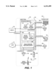
- FIG. 1 is a diagram of an integrated MSC/HLR switch 100 for use in a GSM environment in accordance with this invention.
- Switch 100 which is essentially a central processing unit, is in a Home Public Land Mobile Network (PLMN) 150.
- PLMN 150 includes an equipment identification register (EIR) 130, BSS 135, and MS 140.
- EIR equipment identification register
- BSS 135, and MS 140 are equipment identification registers.
- Home PLMN 150 also connects to Foreign PLMN 160, PSTN 170, and Short Message Service-Service Center SMS-SC 180.
- Switch 100 includes two portions: HLR portion 110 and MSC portion 120. Both portions are preferably implemented in software but can be implemented at least partially in hardware.
- HLR portion 110 includes an HLR database 115 and an AUC database 118 (for authentication).
- MSC portion 120 includes VLR 125 as well as the mobile services switching center functionality 128.
- HLR portion 110 includes circuitry or software to detect an HLR overload condition and generate an HLR overload condition signal in response to that condition.
- MSC portion 120 similarly includes circuitry or software to detect an MSC overload condition and generate an MSC overload condition signal in response to that condition.
- MSC portion 120 also includes throttling circuitry or software, responsive to the HLR overload condition signal, for signalling the need for reducing the number of MSC messages received by the switch means.
- the A-interface connects BSS 135 to MSC/HLR switch 100.
- the majority of traffic occurs on the A-interface.
- BSS 135 includes peripherals that use the connection-oriented peripherals in accordance with GSM protocol.
- the BSS peripherals have circuitry or software to limit the messages sent to the CPU in response to MSC portion 120 signalling of a need to reduce MSC messages. This operation is described in greater detail below.
- a C-interface connects MSC 162 in Foreign PLMN 160 to HLR portion 110, and a D interface connects VLR 164 in foreign PLMN 160 to the HLR portion 110.
- a C/D interface connects the HLR/AUC system 166 in Foreign PLMN 160 to MSC portion 120, and another a C/D interface connects HLR portion 110 and MSC portion 120 in switch 100.
- the C-interfaces connect between MSCs and the HLRs
- the D-interfaces connect between the VLRs and the HLRs. These interfaces are often lumped together, however.
- FIG. 1 also shows three other interfaces.
- An E-interface connects SMS-SC 180 to the MSC portion 120, and an F-interface connects EIR 168 in Foreign PLMN 160 and EIR 130 in Home PLMN 150 to mobile services switching center 128.
- the SMS-SC also connects to HLR portion 110 via an SS7 interface.
- the integrated MSC/HLR switch 100 executes both the MSC and HLR overload controls, which are preferably software procedures. Consistent with nonintegrated systems, the MSC overload control monitors the queuing delay for MSC transactions and reports that delay in a manner that the BSS peripherals can detect. Those peripherals perform overload control functions using this information and throttle selected transactions on the A-interface when necessary to keep the queuing delay within acceptable bounds.
- the HLR overload control operates on the C-interface and the D-interface in the same manner that conventional systems do: When the number of HLR transactions awaiting processing exceeds a threshold, the HLR overload control discards HLR transactions arriving on the C- and D-interfaces to keep the number of queued HLR transactions within acceptable bounds.
- HLR portion 110 enqueues incoming TCAP messages in an HLR work queue in HLR portion 110.
- HLR overload periodically control examines the size of this queue to determine whether the overload status is normal or in one of several overload conditions: Minor overload, Major overload, Critical overload.
- HLR overload control When an overload condition occurs, HLR overload control will either abort or discard the incoming TCAP messages on the C- and D-interfaces depending upon the state of the overload. Normally, this is all HLR overload control can do in a nonintegrated system. In an integrated switch such as switch 100, however, this action may be insufficient because traffic can enter on all interfaces.
- HLR overload control sends an overload indication, through the MSC portion 120, to BSS peripherals to throttle incoming MSC transactions at the A-interface. This invention thus properly recognizes that HLR transactions should receive priority over MSC transactions.
- HLR overload control does not throttle all the BSS peripherals. Traffic studies characterizing typical overload conditions show no need for such drastic action. Instead, one may achieve suitable overload control by sending the overload indications to about one fifth of the peripherals.
- a data table in MSC portion 110 divides the peripherals into five groups of roughly equal size.
- HLR overload control makes overload indications available to a group of peripherals. Then, at one second intervals thereafter, HLR control sends overload indications to different groups of peripherals in some pattern until the overload condition clears.
- HLR portion 110 and the MSC portion 120 must jointly perform overload control, and must do so without violating GSM standards.
- This invention allows HLR overload control to effect more overload control.
- the HLR portion 110 and the MSC portion 120 reside on the same switch 100.
- HLR overload control in portion 110 can thus take advantage of this coresidency with MSC portion 120 to reduce A-interface traffic.
- the A-interface is logically connected only to MSC portion 120, but in an integrated system, HLR overload control in portion 110 can send control messages to the A-interface (i.e., BSS) peripherals through the MSC portion 120 to throttle new traffic.
- A-interface i.e., BSS
- This invention implements a theory that the best way to stabilize switch 100 in overload conditions is to shed work at the switch's entry points, particularly the peripherals.
- the best place to do this in GSM systems is at the A-interface because, as explained above, the majority of traffic occurs on the A-interface in such systems.
- the connection-oriented peripherals specifically those on the A-interface, allow such shedding in accordance with the GSM protocol.
- the overload controls according to this invention do not violate any of the GSM standards, because the overload controls for the MSC and HLR in the nonintegrated system provide all the functions provided in the integrated system. Instead, this invention uses those standards creatively by adding an HLR System Overload Control (HLRSOC) procedure.
- HLRSOC HLR System Overload Control
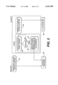
- FIG. 2 shows an example of the relationship between the HLRSOC and standard MSC and HLR overload controls.
- an MSC overload control 210 informs the A-interface peripherals (step 220) when MSC overload conditions occur.
- the HLR overload control algorithm 230 sends discard messages to the C- and D-interfaces when HLR overload conditions occur (step 240).
- HLRSOC procedure 250 queries the existing HLR overload control algorithm (230) every second to look for an overload detection.
- HLRSOC sends a message to selected peripherals on the A-interface (one fifth in the preferred implementation) (step 270).
- This overload control recognizes the fact that the HLR's traffic is to due principally to MSC activity.
- HLR portion 110 becomes overloaded, it alleviates that condition by throttling the MSC traffic.
- Favoring HLR work over MSC work in this manner is proper, especially when the HLR serves other MSCs as well.
- connection-oriented messaging protocol of the A-interface it is better to use the connection-oriented messaging protocol of the A-interface to restore nodal stability rather than the connectionless messaging protocols on the C- and D-interfaces.
- the connection-oriented messaging protocol on the A-interface allows the peripherals to do the actual throttling, thereby relieving the MSC of such responsibilities.
- This system accommodates all the combinations of overload scenarios. For example, if MSC portion 120 is in overload but the HLR portion 110 is not, the overload condition protocol reacts normally to throttle new attempts to make connections on the A-interface.
- HLR portion 110 is in overload on the A-interface, but MSC portion 120 is not, then the HLRSOC will reduce A-interface traffic, as well as discard locally generated transactions, to allow the HLR to stabilize.
- HLR portion 110 If HLR portion 110 is in overload because the external C- and D-interfaces, but MSC portion 120 is not in overload, then the HLR portion 110's internal mechanism will begin aborting transactions and, as indicated above with regard to FIG. 2, will cause throttling of A-interface traffic. This will reduce total nodal loading and allow HLR portion 110's overload control to continue to handle the overload state caused by the external traffic. This allows HLR portion 110 to use as much as switch 100's capacity as possible to reduce its overload condition without starving the MSC portion 120 of work.
- HLR portion 110 and MSC portion 120 are in overload from all interfaces, stabilization will occur quickly. Both HLR portion 110 and MSC portion 120 will send "overloaded" messages to the peripherals which will reduce traffic to the lowest level possible. HLR portion 110 will gain processing time at MSC portion 110's expense, but the overall nodal loading will be reduced.
Abstract
Description
Claims (19)
Priority Applications (1)
| Application Number | Priority Date | Filing Date | Title |
|---|---|---|---|
| US09/121,940 US6151499A (en) | 1995-07-31 | 1998-07-24 | Overload control for an integrated MSC/HLR switch |
Applications Claiming Priority (2)
| Application Number | Priority Date | Filing Date | Title |
|---|---|---|---|
| US08/509,136 US5867787A (en) | 1995-07-31 | 1995-07-31 | Overload control for an integrated MSC/HLR switch |
| US09/121,940 US6151499A (en) | 1995-07-31 | 1998-07-24 | Overload control for an integrated MSC/HLR switch |
Related Parent Applications (1)
| Application Number | Title | Priority Date | Filing Date |
|---|---|---|---|
| US08/509,136 Continuation US5867787A (en) | 1995-07-31 | 1995-07-31 | Overload control for an integrated MSC/HLR switch |
Publications (1)
| Publication Number | Publication Date |
|---|---|
| US6151499A true US6151499A (en) | 2000-11-21 |
Family
ID=24025433
Family Applications (2)
| Application Number | Title | Priority Date | Filing Date |
|---|---|---|---|
| US08/509,136 Expired - Lifetime US5867787A (en) | 1995-07-31 | 1995-07-31 | Overload control for an integrated MSC/HLR switch |
| US09/121,940 Expired - Lifetime US6151499A (en) | 1995-07-31 | 1998-07-24 | Overload control for an integrated MSC/HLR switch |
Family Applications Before (1)
| Application Number | Title | Priority Date | Filing Date |
|---|---|---|---|
| US08/509,136 Expired - Lifetime US5867787A (en) | 1995-07-31 | 1995-07-31 | Overload control for an integrated MSC/HLR switch |
Country Status (1)
| Country | Link |
|---|---|
| US (2) | US5867787A (en) |
Cited By (8)
| Publication number | Priority date | Publication date | Assignee | Title |
|---|---|---|---|---|
| US20020168978A1 (en) * | 1999-07-09 | 2002-11-14 | Valeria Molnar | Method for the restriction of a message service |
| US6718170B1 (en) * | 1999-07-01 | 2004-04-06 | Qualcomm Incorporated | Dynamic allocation of microprocessor resources in a wireless communication device |
| US6751478B1 (en) * | 2000-01-17 | 2004-06-15 | Fujitsu Limited | Mobile-service switch, home memory node, and gateway switch |
| US20060015506A1 (en) * | 2004-06-14 | 2006-01-19 | Nokia Corporation | Full redundant service register in the multi-vendor network |
| US20060248335A1 (en) * | 2005-04-29 | 2006-11-02 | Cisco Technology, Inc. | Configuring interfaces of a switch using templates |
| USRE39878E1 (en) * | 1997-03-14 | 2007-10-09 | Nortel Networks Limited | Method and apparatus for network initiated parameter updating |
| US20110103557A1 (en) * | 2009-11-02 | 2011-05-05 | Alcatel-Lucent Usa Inc. | Overload detection on multi-CPU system |
| CN103118415B (en) * | 2011-11-16 | 2016-06-29 | 华为终端有限公司 | The processing method of a kind of service request and device |
Families Citing this family (18)
| Publication number | Priority date | Publication date | Assignee | Title |
|---|---|---|---|---|
| US6131025A (en) * | 1996-11-20 | 2000-10-10 | Lucent Technologies Inc. | Method for providing ubiquitous service to mobile subscribers using a wireless gateway switch |
| KR100209464B1 (en) * | 1996-11-30 | 1999-07-15 | 김영환 | Dynamic overload controlling method and apparatus in the digital mobile communication system |
| US6169892B1 (en) * | 1997-11-22 | 2001-01-02 | Northern Telecom Limited | Flow control of authentication triplet request for reducing usage time of a central processor |
| US6160875A (en) * | 1997-12-30 | 2000-12-12 | Lg Information & Communications, Ltd. | Method of managing overload of message in the communication system |
| JP2000050362A (en) * | 1998-08-03 | 2000-02-18 | Fujitsu Ltd | Method and device for regulating mobile communication system |
| US7200408B1 (en) * | 1999-12-15 | 2007-04-03 | Lucent Technologies Inc. | Selective blocking in a communication network |
| US7110773B1 (en) * | 2000-04-11 | 2006-09-19 | Telecommunication Systems, Inc. | Mobile activity status tracker |
| EP1310128A1 (en) | 2000-08-09 | 2003-05-14 | Nokia Corporation | Communication system and method for limiting the number of interrogation requests to an information register |
| US7466983B2 (en) * | 2000-09-01 | 2008-12-16 | Telefonaktiebolaget L M Ericsson (Publ) | Overload protection in packet communication networks |
| JP2002171280A (en) * | 2000-12-01 | 2002-06-14 | Sony Corp | Communication system, communication device, and communication method |
| AT411807B (en) * | 2001-02-14 | 2004-05-25 | Universal Comm Platform Ag | METHOD AND DEVICE FOR FORWARDING SHORT MESSAGES FROM A MOBILE TERMINAL |
| GB2372676A (en) * | 2001-02-21 | 2002-08-28 | Ericsson Telefon Ab L M | Preventing overload in a telecommunications system |
| US6819926B2 (en) | 2001-08-03 | 2004-11-16 | Telefonaktiebolaget Lm Ericsson (Publ) | System and method for providing protection from an overload condition within the home location register |
| US7079524B2 (en) * | 2001-10-11 | 2006-07-18 | Tekelec | Methods and systems for off-loading a-interface short message service (SMS) message traffic in a wireless communications network |
| US7310307B1 (en) * | 2002-12-17 | 2007-12-18 | Cisco Technology, Inc. | System and method for authenticating an element in a network environment |
| US20080009284A1 (en) * | 2006-07-07 | 2008-01-10 | Sbc Knowledge Ventures, Lp | Load balancing based on free space of visitor location register |
| US8155056B2 (en) * | 2008-12-11 | 2012-04-10 | Motorola Solutions, Inc. | Method and apparatus for controlling traffic congestion in a wireless communication network |
| US8972455B2 (en) * | 2010-10-19 | 2015-03-03 | Hewlett-Packard Development Company, L.P. | System and method for traffic surge control |
Citations (8)
| Publication number | Priority date | Publication date | Assignee | Title |
|---|---|---|---|---|
| US4670899A (en) * | 1985-05-31 | 1987-06-02 | Northern Telecom Limited | Load balancing for cellular radiotelephone system |
| EP0260763A2 (en) * | 1986-09-18 | 1988-03-23 | Philips Electronics Uk Limited | Radio system |
| US5097499A (en) * | 1990-08-22 | 1992-03-17 | At&T Bell Laboratories | Autonomous registration overload control for cellular mobile radio systems |
| US5257399A (en) * | 1990-11-28 | 1993-10-26 | Telefonaktiebolaget L M Ericsson | Multiple access handling in a cellular communications system |
| US5289179A (en) * | 1991-11-27 | 1994-02-22 | At&T Bell Laboratories | Maintaining stable virtual circuit data connections with spare protocol handler |
| US5396543A (en) * | 1991-11-27 | 1995-03-07 | At&T Corp. | Signaling arrangements in a cellular mobile telecommunications switching system |
| US5548533A (en) * | 1994-10-07 | 1996-08-20 | Northern Telecom Limited | Overload control for a central processor in the switching network of a mobile communications system |
| US5623532A (en) * | 1995-01-12 | 1997-04-22 | Telefonaktiebolaget Lm Ericsson | Hardware and data redundant architecture for nodes in a communications system |
Family Cites Families (1)
| Publication number | Priority date | Publication date | Assignee | Title |
|---|---|---|---|---|
| FR2657477A1 (en) * | 1990-01-19 | 1991-07-26 | Cit Alcatel | METHOD FOR PROTECTION AGAINST DATA SATURATION OF A VISITOR LOCATION RECORDER FOR A CELL RADIOTELEPHONE SYSTEM. |
-
1995
- 1995-07-31 US US08/509,136 patent/US5867787A/en not_active Expired - Lifetime
-
1998
- 1998-07-24 US US09/121,940 patent/US6151499A/en not_active Expired - Lifetime
Patent Citations (8)
| Publication number | Priority date | Publication date | Assignee | Title |
|---|---|---|---|---|
| US4670899A (en) * | 1985-05-31 | 1987-06-02 | Northern Telecom Limited | Load balancing for cellular radiotelephone system |
| EP0260763A2 (en) * | 1986-09-18 | 1988-03-23 | Philips Electronics Uk Limited | Radio system |
| US5097499A (en) * | 1990-08-22 | 1992-03-17 | At&T Bell Laboratories | Autonomous registration overload control for cellular mobile radio systems |
| US5257399A (en) * | 1990-11-28 | 1993-10-26 | Telefonaktiebolaget L M Ericsson | Multiple access handling in a cellular communications system |
| US5289179A (en) * | 1991-11-27 | 1994-02-22 | At&T Bell Laboratories | Maintaining stable virtual circuit data connections with spare protocol handler |
| US5396543A (en) * | 1991-11-27 | 1995-03-07 | At&T Corp. | Signaling arrangements in a cellular mobile telecommunications switching system |
| US5548533A (en) * | 1994-10-07 | 1996-08-20 | Northern Telecom Limited | Overload control for a central processor in the switching network of a mobile communications system |
| US5623532A (en) * | 1995-01-12 | 1997-04-22 | Telefonaktiebolaget Lm Ericsson | Hardware and data redundant architecture for nodes in a communications system |
Cited By (11)
| Publication number | Priority date | Publication date | Assignee | Title |
|---|---|---|---|---|
| USRE39878E1 (en) * | 1997-03-14 | 2007-10-09 | Nortel Networks Limited | Method and apparatus for network initiated parameter updating |
| US6718170B1 (en) * | 1999-07-01 | 2004-04-06 | Qualcomm Incorporated | Dynamic allocation of microprocessor resources in a wireless communication device |
| US20020168978A1 (en) * | 1999-07-09 | 2002-11-14 | Valeria Molnar | Method for the restriction of a message service |
| US6751478B1 (en) * | 2000-01-17 | 2004-06-15 | Fujitsu Limited | Mobile-service switch, home memory node, and gateway switch |
| US20060015506A1 (en) * | 2004-06-14 | 2006-01-19 | Nokia Corporation | Full redundant service register in the multi-vendor network |
| US8295813B2 (en) * | 2004-06-14 | 2012-10-23 | Nokia Siemens Networks Oy | Full redundant service register in the multi-vendor network |
| US20060248335A1 (en) * | 2005-04-29 | 2006-11-02 | Cisco Technology, Inc. | Configuring interfaces of a switch using templates |
| US8108673B2 (en) * | 2005-04-29 | 2012-01-31 | Cisco Technology, Inc. | Configuring interfaces of a switch using templates |
| US8397278B2 (en) | 2005-04-29 | 2013-03-12 | Cisco Technology, Inc. | Configuring interfaces of a switch using templates |
| US20110103557A1 (en) * | 2009-11-02 | 2011-05-05 | Alcatel-Lucent Usa Inc. | Overload detection on multi-CPU system |
| CN103118415B (en) * | 2011-11-16 | 2016-06-29 | 华为终端有限公司 | The processing method of a kind of service request and device |
Also Published As
| Publication number | Publication date |
|---|---|
| US5867787A (en) | 1999-02-02 |
Similar Documents
| Publication | Publication Date | Title |
|---|---|---|
| US6151499A (en) | Overload control for an integrated MSC/HLR switch | |
| EP1142371B1 (en) | System and method for coordinating notification requests for terminal availability | |
| US5579372A (en) | Flow control method for short message service - busy subscriber | |
| EP1033043B1 (en) | Retention of radio resource connection for short message service message deliviery in a cellular telephone network | |
| CA2024305C (en) | Control of overload in communications networks | |
| US5548533A (en) | Overload control for a central processor in the switching network of a mobile communications system | |
| US6064892A (en) | Traffic management system with overload control functions for use in a telecommunications system | |
| EP1185123A1 (en) | Method for limiting the number of simultaneous call forwarding attempts in a cellular communication system | |
| US6233447B1 (en) | Mobile communication system and a method of incoming call restriction | |
| US9681303B2 (en) | Method for fraud recognition in the case of roaming connections in mobile communications networks | |
| US6463291B1 (en) | Short message queuing mechanism | |
| US6850760B2 (en) | Method and devices for improved location updating in a mobile communication system | |
| US6097955A (en) | Apparatus and method for optimizing CPU usage in processing paging messages within a cellular communications system | |
| GB2350918A (en) | Paging in a mobile telecommunications network | |
| JP2000515695A (en) | Dynamic load shedding | |
| US20030048789A1 (en) | Packet call routing in a mobile communication network | |
| WO1999056478A1 (en) | An announcing system and method used in a communications network for holding incoming circuit switched calls | |
| EP2291041A2 (en) | Paging system | |
| JPH09501028A (en) | Intelligent network | |
| KR100199014B1 (en) | Base station call control method for mobile communication system | |
| KR100321081B1 (en) | The method for managing load state of base station controller in personal communication exchange system | |
| KR0175598B1 (en) | Low probability connection call registration method by automatic congestion level | |
| US6317601B1 (en) | Automatic code gapping (ACG) for wireless systems | |
| GB2307374A (en) | Optimised Trigger List For Use in Intelligent Network Communications System | |
| KR20010063353A (en) | Overload control method in the hlr |
Legal Events
| Date | Code | Title | Description |
|---|---|---|---|
| AS | Assignment |
Owner name: NORTEL NETWORKS CORPORATION, CANADA Free format text: CHANGE OF NAME;ASSIGNOR:NORTHERN TELECOM LIMITED;REEL/FRAME:010567/0001 Effective date: 19990429 |
|
| AS | Assignment |
Owner name: NORTEL NETWORKS LIMITED, CANADA Free format text: CHANGE OF NAME;ASSIGNOR:NORTEL NETWORKS CORPORATION;REEL/FRAME:011195/0706 Effective date: 20000830 Owner name: NORTEL NETWORKS LIMITED,CANADA Free format text: CHANGE OF NAME;ASSIGNOR:NORTEL NETWORKS CORPORATION;REEL/FRAME:011195/0706 Effective date: 20000830 |
|
| STCF | Information on status: patent grant |
Free format text: PATENTED CASE |
|
| FPAY | Fee payment |
Year of fee payment: 4 |
|
| FPAY | Fee payment |
Year of fee payment: 8 |
|
| FEPP | Fee payment procedure |
Free format text: PAYOR NUMBER ASSIGNED (ORIGINAL EVENT CODE: ASPN); ENTITY STATUS OF PATENT OWNER: LARGE ENTITY |
|
| AS | Assignment |
Owner name: KAPSCH CARRIERCOM FRANCE S.A.S., FRANCE Free format text: ASSIGNMENT OF ASSIGNORS INTEREST;ASSIGNOR:NORTEL NETWORKS LIMITED;REEL/FRAME:024838/0038 Effective date: 20100331 |
|
| FPAY | Fee payment |
Year of fee payment: 12 |
|
| AS | Assignment |
Owner name: LENOVO GROUP LIMITED, HONG KONG Free format text: ASSIGNMENT OF ASSIGNORS INTEREST;ASSIGNOR:KAPSCH CARRIERCOM FRANCE SAS;REEL/FRAME:033236/0617 Effective date: 20140614 |
|
| AS | Assignment |
Owner name: LENOVO INNOVATIONS LIMITED (HK), HONG KONG Free format text: ASSIGNMENT OF ASSIGNORS INTEREST;ASSIGNOR:LENOVO GROUP LIMITED;REEL/FRAME:038067/0571 Effective date: 20151124 |