US6151537A - Method for determining tractive force required at the wheels of a vehicle - Google Patents
Method for determining tractive force required at the wheels of a vehicle Download PDFInfo
- Publication number
- US6151537A US6151537A US09/092,375 US9237598A US6151537A US 6151537 A US6151537 A US 6151537A US 9237598 A US9237598 A US 9237598A US 6151537 A US6151537 A US 6151537A
- Authority
- US
- United States
- Prior art keywords
- vehicle
- total
- determining
- speed
- effort
- Prior art date
- Legal status (The legal status is an assumption and is not a legal conclusion. Google has not performed a legal analysis and makes no representation as to the accuracy of the status listed.)
- Expired - Lifetime
Links
- 238000000034 method Methods 0.000 title claims abstract description 31
- 238000005096 rolling process Methods 0.000 claims abstract description 14
- 238000012937 correction Methods 0.000 claims abstract description 8
- 230000003068 static effect Effects 0.000 claims description 5
- 230000005540 biological transmission Effects 0.000 description 7
- 238000012360 testing method Methods 0.000 description 7
- 230000003466 anti-cipated effect Effects 0.000 description 5
- 238000013461 design Methods 0.000 description 4
- 238000001816 cooling Methods 0.000 description 2
- 238000006073 displacement reaction Methods 0.000 description 2
- 230000007613 environmental effect Effects 0.000 description 2
- 238000010521 absorption reaction Methods 0.000 description 1
- 239000002826 coolant Substances 0.000 description 1
- 238000011161 development Methods 0.000 description 1
- 238000012986 modification Methods 0.000 description 1
- 230000004048 modification Effects 0.000 description 1
- 238000012546 transfer Methods 0.000 description 1
- XLYOFNOQVPJJNP-UHFFFAOYSA-N water Substances O XLYOFNOQVPJJNP-UHFFFAOYSA-N 0.000 description 1
Images


Classifications
-
- G—PHYSICS
- G01—MEASURING; TESTING
- G01L—MEASURING FORCE, STRESS, TORQUE, WORK, MECHANICAL POWER, MECHANICAL EFFICIENCY, OR FLUID PRESSURE
- G01L5/00—Apparatus for, or methods of, measuring force, work, mechanical power, or torque, specially adapted for specific purposes
- G01L5/13—Apparatus for, or methods of, measuring force, work, mechanical power, or torque, specially adapted for specific purposes for measuring the tractive or propulsive power of vehicles
-
- B—PERFORMING OPERATIONS; TRANSPORTING
- B60—VEHICLES IN GENERAL
- B60W—CONJOINT CONTROL OF VEHICLE SUB-UNITS OF DIFFERENT TYPE OR DIFFERENT FUNCTION; CONTROL SYSTEMS SPECIALLY ADAPTED FOR HYBRID VEHICLES; ROAD VEHICLE DRIVE CONTROL SYSTEMS FOR PURPOSES NOT RELATED TO THE CONTROL OF A PARTICULAR SUB-UNIT
- B60W2300/00—Indexing codes relating to the type of vehicle
- B60W2300/14—Trailers, e.g. full trailers, caravans
-
- B—PERFORMING OPERATIONS; TRANSPORTING
- B60—VEHICLES IN GENERAL
- B60W—CONJOINT CONTROL OF VEHICLE SUB-UNITS OF DIFFERENT TYPE OR DIFFERENT FUNCTION; CONTROL SYSTEMS SPECIALLY ADAPTED FOR HYBRID VEHICLES; ROAD VEHICLE DRIVE CONTROL SYSTEMS FOR PURPOSES NOT RELATED TO THE CONTROL OF A PARTICULAR SUB-UNIT
- B60W2530/00—Input parameters relating to vehicle conditions or values, not covered by groups B60W2510/00 or B60W2520/00
- B60W2530/16—Driving resistance
Definitions
- This invention relates to methods for predicting the performance of a motor vehicle under specified conditions, and more particularly to a method for determining the tractive effort required to propel a vehicle at a given speed under a given set of conditions, to thereby aid designers and engineers in predicting the performance of various engine, drive train and aerodynamic configurations of a vehicle during design and testing of the vehicle.
- Some performance factors to be considered are whether the engine to be used is capable of providing enough power for the tasks which the vehicle will be expected to perform. Such tasks might include towing trailers, boats or other items, traveling frequently in geographic areas where steep grades are frequently encountered or in areas where the altitude may affect the performance of the vehicle engine.
- the gross vehicle weight i.e., the weight of the vehicle plus the additional weight "seen” by the vehicle if the vehicle is towing a trailer
- the gross vehicle weight i.e., the weight of the vehicle plus the additional weight "seen” by the vehicle if the vehicle is towing a trailer
- the engine to be used in the vehicle will be powerful enough to provide sufficient power to move the vehicle under all of the wide ranging conditions that the vehicle may be expected to encounter. It would also be helpful for the designer to be able to predict whether a particular transmission, transfer case or axle will perform adequately when packaged with an engine having a particular displacement.
- the present invention relates to a method for determining the tractive effort required at the wheels of a vehicle under a given set of conditions and loads to maintain the vehicle at a desired speed.
- the method enables an engineer or designer to predict the tractive effort that will be required to move the vehicle at a desired speed under a wide variety of load conditions by simply inputting a number of variables relating to the various components of the vehicle such as the engine, transmission, vehicle weight, etc.
- the method principally involves determining an approximate rolling effort required to maintain the vehicle moving at a speed in accordance with a desired speed; determining an aerodynamic influence factor representative of an aerodynamic resistance which the vehicle is to be exposed to at the desired speed; and using the approximate rolling effort and the dynamic influence factor to determine the total resistance force needed to be overcome to move the vehicle at the desired speed.
- the step of determining the aerodynamic influence factor comprises determining the drag coefficient of the vehicle and the vehicle's frontal area, and using these factors to determine the aerodynamic influence factor.
- the drag coefficient of a trailer or any other implement which the vehicle is expected to tow, as well as the total frontal area of the implement may be taken into consideration to further modify the aerodynamic influence factor.
- a total grade effort value is determined and also used in determining the total tractive effort value.
- the total grade effort value is determined by taking the grade of a surface on which the vehicle is expected to travel together with the gross vehicle weight and using these two factors to produce the total grade effort value. This force represents the force required to move the vehicle at a desired speed while the vehicle is travelling on the specified grade.
- the ambient temperature of the environment in which the vehicle is to be operated is taken into account together with the barometric pressure. These two factors are then combined to produce a correction factor which is also applied in determining the aerodynamic influence factor.
- the static factor of one tire of the vehicle is taken into account together with a variable representing the tire tangential speed when the vehicle is traveling at the desired vehicle speed.
- the method of the present invention therefore provides a means by which an engineer or vehicle designer can predict the tractive force which will be required at the wheels of a vehicle under a wide variety of operating conditions when using a wide variety of vehicle configurations.
- This information can be easily plotted in spread-sheet or graphical format with a personal computer or a lap top computer in readily available commercial software in graphical form and compared with existing data or graphs of output power available from specific engine, transmission and drive train packages. This enables the engineer to quickly determine, without actually testing a vehicle, whether the engine and drive train combination, as well as the vehicle aerodynamics, will likely permit the vehicle to perform under the conditions which engineers and designers expect will be required of the vehicle.
- the method of the present invention further provides the significant advantage of providing a model into which a number of well known variables can be input to produce the tractive effort determinations needed to predict vehicle performance.
- the method of the present invention can be implemented even by individuals not having extensive engineering experience.
- the method further provides the advantage of standardizing how vehicle performance is predicted so that consistency and repeatability among vehicles of the same type, and further between different vehicles, can be achieved.
- FIG. 1 is a flow chart of the method of the present invention illustrating the variables taken into account in determining the tractive force and power required at the wheels of a vehicle for the purpose of predicting vehicle performance under specified operating conditions and with specified engine, drive train and aerodynamic packages;
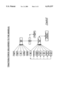
- FIG. 2 is a flowchart of the factors typically taken into account in determining the tractive force available at the wheels of a vehicle.
- FIG. 3 is a graph illustrating the tractive force available at the vehicle wheels for different gears and one vehicle configuration and the tractive effort required at various vehicle speeds.
- a method 10 is illustrated for determining the tractive effort required at the wheels of a vehicle in accordance with a preferred embodiment of the present invention.
- the total tractive effort is determined by summing a total grade effort force value generated at step 14, an approximate value of the rolling effort required to move the vehicle due to the hysterisis of the vehicle's tires, as indicated at step 16, and an aerodynamic influence factor generated at step 20, which is representative of the total air resistance which the vehicle experiences while moving at any given speed.
- the total tractive effort determination made at step 12 which therefore represents all of the train resistance forces (i.e, grade, aerodynamic and rolling forces), may be plotted on a vehicle tractability chart 21 and compared against a tractive force available at the wheels of a given vehicle model having a specific engine, specific drive train and specific aerodynamic package. This feature will be described in more detail in the following paragraphs.
- the method of the present invention further can be used easily with conventional dynamometers. If so used, a dynamometer power absorption factor can be selected, as indicated at step 22, and applied to further help in predicting vehicle performance in a wind tunnel.
- the total grade effort value at step 14 is determined by considering the grade profile, as indicated at step 24, the net weight of a trailer or any other object being towed by the vehicle, as indicated at step 26, and the gross vehicle weight, as indicated at step 28.
- the gross vehicle weight (GVW) is the total weight of the vehicle loaded to the maximum amount that the vehicle's tires or its structure permit, including the tongue weight, obtained at step 30, of the trailer or object being towed.
- the tongue weight is that weight which the hitch of the vehicle "sees" when the trailer or object is secured to the hitch.
- the tongue weight at step 30 is readily derived in a well known manner from the gross trailer weight, as indicated at step 32. Taking the information obtained at steps 24, 26 and 28, the total grade effort value can be determined using the formula:
- GRADE equals the grade percentage value in step 24 of the grade of the surface that the tire pressure of at least one tire, the vehicle must travel on.
- the approximate total rolling effort is determined by taking the static factor of the tire, known in the industry as the tire's "fo-coefficient", as indicated at step 34, the tire tangential speed, which is also available from look-up tables known in the art and designated as the “fs speed coefficient”, as indicated at step 36, and the vehicle speed at step 38, and using these factors in connection with the following formula:
- fo-coefficient equals the rolling resistance of a radial tire as determined from a lookup table
- MPH equals the desired vehicle speed in miles per hour.
- an environmental correction factor can optionally be determined, as indicated at step 40.
- This environmental correction factor if incorporated, is determined by taking into account the ambient temperature, as indicated at step 42, and the barometric pressure, as indicated at step 44. These two factors are then used to generate the correction factor by the following formula:
- T the ambient temperature
- the aerodynamic influence factor determined at step 20 is determined by taking into account the product of the vehicle drag coefficient (Cd v ) and the total frontal area of the vehicle, as indicated at step 46, the air velocity which the vehicle experiences, as indicated at step 48, and the product of the drag coefficient (Cd t ) of a trailer or other implement being towed by the vehicle and the total frontal area of the trailer or implement to calculate a total trailer drag coefficient, as indicated at step 50.
- the air velocity determined at step 48 is determined by taking into account the wind speed that the vehicle experiences, as indicated at step 52, and the vehicle speed, as indicated at step 54.
- the aerodynamic influence factor is determined by the following formula:
- A total frontal area of the vehicle and trailer or other implement being towed
- Total cd total combined drag coefficient of the vehicle and outside mirrors.
- the total tractive effort value, determined at step 12, is determined by summing the force values determined at steps 14, 16 and 18 to produce a total force value representative of all the train resistance forces (i.e., grade, aerodynamic and rolling forces) which make up the tractive effort required at the wheels of the motor vehicle.
- Curve 56 is the tractive force available in first gear at various vehicle speeds
- curve 58 is the force available in second gear
- curve 60 is the force available in third gear
- curve 62 is the force available in fourth gear.
- Curves 64, 66 and 68 represent the tractive force required at the wheels for three different vehicle configurations. From FIG. 3, it can be seen that, for example at point 70, the tractive effort required to sustain a vehicle speed of 75 MPH cannot be met in any one of first, second, third or fourth gears.
- Vehicle configuration number 2 as designated by curve 66, can, however, be met at this speed, as indicated by the intersection of curve 60 with curve 66 at point 72.
- the method of the present invention allows vehicle engineers and designers to quickly determine if the vehicle will be able to provide the tractive force necessary at the wheels of a vehicle to meet the tractive force required under the designated conditions at various operating speeds. Accordingly, the engineer or designer can quickly determine if a particular vehicle configuration will simply not be able to provide sufficient tractive force to meet the tractive effort required under various operating conditions.
- the method of the present invention further enables the engineer or designer to change one or more variables and to predict the tractive effort required at the vehicles wheels in advance of performing any actual testing on the vehicle. It will be appreciated that the method of the present invention can significantly streamline and accelerate the development and testing of various vehicle configurations by allowing designers to predict more closely the tractive effort required for different vehicle configurations and widely varying operating conditions prior to physically assembling and testing a vehicle having a particular configuration.
Abstract
Description
Total Grade Effort=GVW·SIN(TAN.sup.-1 (GRADE/100))
Total rolling effort=combined GVW·(fo+(fs×3.24)×(MPH÷100).sup.2.5)
Temperature Correction Factor (T.sub.COIT)=(0.075÷32.174)·(460+70)·(460+T).multidot.(P.sub.b ÷29.92)
1.076·Total.sub.cd ·A·T.sub.COIT ·MPH.sup.2
Claims (5)
Priority Applications (1)
| Application Number | Priority Date | Filing Date | Title |
|---|---|---|---|
| US09/092,375 US6151537A (en) | 1998-06-05 | 1998-06-05 | Method for determining tractive force required at the wheels of a vehicle |
Applications Claiming Priority (1)
| Application Number | Priority Date | Filing Date | Title |
|---|---|---|---|
| US09/092,375 US6151537A (en) | 1998-06-05 | 1998-06-05 | Method for determining tractive force required at the wheels of a vehicle |
Publications (1)
| Publication Number | Publication Date |
|---|---|
| US6151537A true US6151537A (en) | 2000-11-21 |
Family
ID=22232915
Family Applications (1)
| Application Number | Title | Priority Date | Filing Date |
|---|---|---|---|
| US09/092,375 Expired - Lifetime US6151537A (en) | 1998-06-05 | 1998-06-05 | Method for determining tractive force required at the wheels of a vehicle |
Country Status (1)
| Country | Link |
|---|---|
| US (1) | US6151537A (en) |
Cited By (13)
| Publication number | Priority date | Publication date | Assignee | Title |
|---|---|---|---|---|
| US6604025B2 (en) * | 2000-06-14 | 2003-08-05 | Robert Bosch Gmbh | Method and device for ascertaining the laden state of a vehicle |
| US20050090964A1 (en) * | 2003-10-27 | 2005-04-28 | Jan Ryderstam | Tractive force map |
| US20050275081A1 (en) * | 2004-06-12 | 2005-12-15 | Roger Chang | Embedded chip semiconductor having dual electronic connection faces |
| US20070251740A1 (en) * | 2004-06-15 | 2007-11-01 | Caterpillar Inc. | Method for controlling an electric drive machine |
| US20090006007A1 (en) * | 2007-06-29 | 2009-01-01 | Caterpillar Inc. | System and method for measuring machine rolling resistance |
| US20090143937A1 (en) * | 2007-12-04 | 2009-06-04 | Lockheed Martin Corporation | GPS-based traction control system using wirelessly received weather data |
| US8145402B2 (en) | 2007-12-05 | 2012-03-27 | Lockheed Martin Corporation | GPS-based traction control system and method using data transmitted between vehicles |
| US8229639B2 (en) | 2009-02-17 | 2012-07-24 | Lockheed Martin Corporation | System and method for stability control |
| US8244442B2 (en) | 2009-02-17 | 2012-08-14 | Lockheed Martin Corporation | System and method for stability control of vehicle and trailer |
| US8352120B2 (en) | 2009-02-17 | 2013-01-08 | Lockheed Martin Corporation | System and method for stability control using GPS data |
| US8589049B2 (en) | 2007-12-03 | 2013-11-19 | Lockheed Martin Corporation | GPS-based system and method for controlling vehicle characteristics based on terrain |
| US20210129670A1 (en) * | 2019-10-31 | 2021-05-06 | Deere & Company | Trailing vehicle traction control system with force increase control |
| US20220237952A1 (en) * | 2021-01-27 | 2022-07-28 | Ford Global Technologies, Llc | Systems and methods for modeling electric vehicle towing |
Citations (8)
| Publication number | Priority date | Publication date | Assignee | Title |
|---|---|---|---|---|
| US3695673A (en) * | 1970-09-11 | 1972-10-03 | James H Meadows | Air-flow diverter for tractor-trailer rig |
| US3929369A (en) * | 1973-03-19 | 1975-12-30 | Blair Lefler Inc | Air deflecting vane assembly for a vehicle |
| US4964481A (en) * | 1984-01-13 | 1990-10-23 | Honda Giken Kogyo Kabushiki Kaisha | Steering system for vehicles |
| US5428531A (en) * | 1991-03-13 | 1995-06-27 | Mitsubishi Jidosha Kogyo Kabushiki Kaisha | Speed change control method for setting a gearshift position of an automatic transmission for vehicles based upon driver acceleration intention and external variables |
| US5508924A (en) * | 1992-03-19 | 1996-04-16 | Kabushikikaisha Equos Research | Driving force controller for an electric vehicle with electric motors provided for all driving wheels individually |
| US5517410A (en) * | 1993-07-08 | 1996-05-14 | Toyota Jidosha Kabushiki Kaisha | Apparatus for controlling vehicle drive force depending upon vehicle load determined by engine load and vehicle speed |
| US5563792A (en) * | 1992-11-12 | 1996-10-08 | Ford Motor Company | Vehicular surface traction characteristic estimation techniques |
| US5921780A (en) * | 1996-06-28 | 1999-07-13 | Myers; Nicole J. | Racecar simulator and driver training system and method |
-
1998
- 1998-06-05 US US09/092,375 patent/US6151537A/en not_active Expired - Lifetime
Patent Citations (8)
| Publication number | Priority date | Publication date | Assignee | Title |
|---|---|---|---|---|
| US3695673A (en) * | 1970-09-11 | 1972-10-03 | James H Meadows | Air-flow diverter for tractor-trailer rig |
| US3929369A (en) * | 1973-03-19 | 1975-12-30 | Blair Lefler Inc | Air deflecting vane assembly for a vehicle |
| US4964481A (en) * | 1984-01-13 | 1990-10-23 | Honda Giken Kogyo Kabushiki Kaisha | Steering system for vehicles |
| US5428531A (en) * | 1991-03-13 | 1995-06-27 | Mitsubishi Jidosha Kogyo Kabushiki Kaisha | Speed change control method for setting a gearshift position of an automatic transmission for vehicles based upon driver acceleration intention and external variables |
| US5508924A (en) * | 1992-03-19 | 1996-04-16 | Kabushikikaisha Equos Research | Driving force controller for an electric vehicle with electric motors provided for all driving wheels individually |
| US5563792A (en) * | 1992-11-12 | 1996-10-08 | Ford Motor Company | Vehicular surface traction characteristic estimation techniques |
| US5517410A (en) * | 1993-07-08 | 1996-05-14 | Toyota Jidosha Kabushiki Kaisha | Apparatus for controlling vehicle drive force depending upon vehicle load determined by engine load and vehicle speed |
| US5921780A (en) * | 1996-06-28 | 1999-07-13 | Myers; Nicole J. | Racecar simulator and driver training system and method |
Cited By (19)
| Publication number | Priority date | Publication date | Assignee | Title |
|---|---|---|---|---|
| US6604025B2 (en) * | 2000-06-14 | 2003-08-05 | Robert Bosch Gmbh | Method and device for ascertaining the laden state of a vehicle |
| US20050090964A1 (en) * | 2003-10-27 | 2005-04-28 | Jan Ryderstam | Tractive force map |
| US7769520B2 (en) * | 2003-10-27 | 2010-08-03 | Ford Global Technologies, Llc | Tractive force map |
| US20050275081A1 (en) * | 2004-06-12 | 2005-12-15 | Roger Chang | Embedded chip semiconductor having dual electronic connection faces |
| US20070251740A1 (en) * | 2004-06-15 | 2007-11-01 | Caterpillar Inc. | Method for controlling an electric drive machine |
| US7350611B2 (en) | 2004-06-15 | 2008-04-01 | Caterpillar Inc | Method for controlling an electric drive machine |
| US20090006007A1 (en) * | 2007-06-29 | 2009-01-01 | Caterpillar Inc. | System and method for measuring machine rolling resistance |
| WO2009005660A2 (en) * | 2007-06-29 | 2009-01-08 | Caterpillar Inc. | System and method for measuring machine rolling resistance |
| US7483808B2 (en) * | 2007-06-29 | 2009-01-27 | Caterpillar Inc. | System and method for measuring machine rolling resistance |
| WO2009005660A3 (en) * | 2007-06-29 | 2010-01-14 | Caterpillar Inc. | System and method for measuring machine rolling resistance |
| US8589049B2 (en) | 2007-12-03 | 2013-11-19 | Lockheed Martin Corporation | GPS-based system and method for controlling vehicle characteristics based on terrain |
| US20090143937A1 (en) * | 2007-12-04 | 2009-06-04 | Lockheed Martin Corporation | GPS-based traction control system using wirelessly received weather data |
| US8145402B2 (en) | 2007-12-05 | 2012-03-27 | Lockheed Martin Corporation | GPS-based traction control system and method using data transmitted between vehicles |
| US8229639B2 (en) | 2009-02-17 | 2012-07-24 | Lockheed Martin Corporation | System and method for stability control |
| US8244442B2 (en) | 2009-02-17 | 2012-08-14 | Lockheed Martin Corporation | System and method for stability control of vehicle and trailer |
| US8352120B2 (en) | 2009-02-17 | 2013-01-08 | Lockheed Martin Corporation | System and method for stability control using GPS data |
| US20210129670A1 (en) * | 2019-10-31 | 2021-05-06 | Deere & Company | Trailing vehicle traction control system with force increase control |
| US11872885B2 (en) * | 2019-10-31 | 2024-01-16 | Deere & Company | Trailing vehicle traction control system with force increase control |
| US20220237952A1 (en) * | 2021-01-27 | 2022-07-28 | Ford Global Technologies, Llc | Systems and methods for modeling electric vehicle towing |
Similar Documents
| Publication | Publication Date | Title |
|---|---|---|
| Wong | Theory of ground vehicles | |
| US6151537A (en) | Method for determining tractive force required at the wheels of a vehicle | |
| Sandberg | Heavy truck modeling for fuel consumption. Simulations and measurements | |
| US20180194357A1 (en) | Determining Weight of Electric and Hybrid Vehicles | |
| US20020056314A1 (en) | Vehicle state analysis system and its analysis method | |
| US10612961B2 (en) | Method for real-time mass estimation of a vehicle system | |
| Gillespie | Vehicle dynamics | |
| DiPierro et al. | A reverse-engineering method for powertrain parameters characterization applied to a P2 plug-in hybrid electric vehicle with automatic transmission | |
| Buggaveeti et al. | Longitudinal vehicle dynamics modeling and parameter estimation for plug-in hybrid electric vehicle | |
| Batra et al. | Anti-jerk dynamic modeling and parameter identification of an electric vehicle based on road tests | |
| Buckley Jr | ABCD-An improved coast down test and analysis method | |
| CN111563312A (en) | Heavy commercial vehicle fuel consumption simulation calculation system | |
| Newman et al. | Development of greenhouse gas emissions model (GEM) for heavy-and medium-duty vehicle compliance | |
| Küçükay et al. | Requirement Engineering using the 3D method | |
| Pettersson et al. | Comparison of dual and single clutch transmission based on Global Transport Application mission profiles | |
| da Silva et al. | Simulation-Driven Model-Based Approach for the Performance and Fuel Efficiency Trade-Off Evaluation of Vehicle Powertrain | |
| Beckers et al. | A microscopic energy consumption prediction tool for fully electric delivery vans | |
| Petersen et al. | Nonlinear vehicle performance simulation with test correlation and sensitivity analysis | |
| KR100377810B1 (en) | Apparatus and Method for predicting fuel comsumption rate of vehicle | |
| Nurhadi et al. | Computer simulation of vehicle performance | |
| KR20230158673A (en) | A fuel efficiency prediction apparatus and method according to the driving speed | |
| Hellmold et al. | Aerodynamic Development of a New Coach Generation Based on Wind Tunnel Testing, CFD-Simulation and On Road Tests | |
| Sandberg | Modeling and validation of traveling resistance for heavy trucks | |
| Jehlik et al. | Real-world thermal effects on wheel assembly efficiency of conventional and electric vehicles | |
| Phillips et al. | A PC–based vehicle powertrain simulation for fuel economy and performance studies |
Legal Events
| Date | Code | Title | Description |
|---|---|---|---|
| AS | Assignment |
Owner name: CHRYSLER CORPORATION, MICHIGAN Free format text: ASSIGNMENT OF ASSIGNORS INTEREST;ASSIGNORS:GHEORDUNESCU, CRISTIAN;NAWROCKI, DONALD A.;REEL/FRAME:009302/0305;SIGNING DATES FROM 19980522 TO 19980601 |
|
| STCF | Information on status: patent grant |
Free format text: PATENTED CASE |
|
| FPAY | Fee payment |
Year of fee payment: 4 |
|
| AS | Assignment |
Owner name: WILMINGTON TRUST COMPANY, DELAWARE Free format text: GRANT OF SECURITY INTEREST IN PATENT RIGHTS - FIRST PRIORITY;ASSIGNOR:CHRYSLER LLC;REEL/FRAME:019773/0001 Effective date: 20070803 Owner name: WILMINGTON TRUST COMPANY,DELAWARE Free format text: GRANT OF SECURITY INTEREST IN PATENT RIGHTS - FIRST PRIORITY;ASSIGNOR:CHRYSLER LLC;REEL/FRAME:019773/0001 Effective date: 20070803 |
|
| AS | Assignment |
Owner name: WILMINGTON TRUST COMPANY, DELAWARE Free format text: GRANT OF SECURITY INTEREST IN PATENT RIGHTS - SECOND PRIORITY;ASSIGNOR:CHRYSLER LLC;REEL/FRAME:019767/0810 Effective date: 20070803 Owner name: WILMINGTON TRUST COMPANY,DELAWARE Free format text: GRANT OF SECURITY INTEREST IN PATENT RIGHTS - SECOND PRIORITY;ASSIGNOR:CHRYSLER LLC;REEL/FRAME:019767/0810 Effective date: 20070803 |
|
| FPAY | Fee payment |
Year of fee payment: 8 |
|
| AS | Assignment |
Owner name: DAIMLERCHRYSLER CORPORATION, MICHIGAN Free format text: CHANGE OF NAME;ASSIGNOR:CHRYSLER CORPORATION;REEL/FRAME:021826/0034 Effective date: 19981116 |
|
| AS | Assignment |
Owner name: CHRYSLER LLC, MICHIGAN Free format text: CHANGE OF NAME;ASSIGNOR:DAIMLERCHRYSLER COMPANY LLC;REEL/FRAME:021832/0233 Effective date: 20070727 Owner name: DAIMLERCHRYSLER COMPANY LLC, MICHIGAN Free format text: CHANGE OF NAME;ASSIGNOR:DAIMLERCHRYSLER CORPORATION;REEL/FRAME:021832/0256 Effective date: 20070329 |
|
| AS | Assignment |
Owner name: US DEPARTMENT OF THE TREASURY, DISTRICT OF COLUMBI Free format text: GRANT OF SECURITY INTEREST IN PATENT RIGHTS - THIR;ASSIGNOR:CHRYSLER LLC;REEL/FRAME:022259/0188 Effective date: 20090102 Owner name: US DEPARTMENT OF THE TREASURY,DISTRICT OF COLUMBIA Free format text: GRANT OF SECURITY INTEREST IN PATENT RIGHTS - THIR;ASSIGNOR:CHRYSLER LLC;REEL/FRAME:022259/0188 Effective date: 20090102 |
|
| AS | Assignment |
Owner name: CHRYSLER LLC, MICHIGAN Free format text: RELEASE BY SECURED PARTY;ASSIGNOR:US DEPARTMENT OF THE TREASURY;REEL/FRAME:022910/0273 Effective date: 20090608 |
|
| AS | Assignment |
Owner name: CHRYSLER LLC, MICHIGAN Free format text: RELEASE OF SECURITY INTEREST IN PATENT RIGHTS - FIRST PRIORITY;ASSIGNOR:WILMINGTON TRUST COMPANY;REEL/FRAME:022910/0498 Effective date: 20090604 Owner name: CHRYSLER LLC, MICHIGAN Free format text: RELEASE OF SECURITY INTEREST IN PATENT RIGHTS - SECOND PRIORITY;ASSIGNOR:WILMINGTON TRUST COMPANY;REEL/FRAME:022910/0740 Effective date: 20090604 Owner name: NEW CARCO ACQUISITION LLC, MICHIGAN Free format text: ASSIGNMENT OF ASSIGNORS INTEREST;ASSIGNOR:CHRYSLER LLC;REEL/FRAME:022915/0001 Effective date: 20090610 Owner name: THE UNITED STATES DEPARTMENT OF THE TREASURY, DIST Free format text: SECURITY AGREEMENT;ASSIGNOR:NEW CARCO ACQUISITION LLC;REEL/FRAME:022915/0489 Effective date: 20090610 Owner name: CHRYSLER LLC,MICHIGAN Free format text: RELEASE OF SECURITY INTEREST IN PATENT RIGHTS - FIRST PRIORITY;ASSIGNOR:WILMINGTON TRUST COMPANY;REEL/FRAME:022910/0498 Effective date: 20090604 Owner name: CHRYSLER LLC,MICHIGAN Free format text: RELEASE OF SECURITY INTEREST IN PATENT RIGHTS - SECOND PRIORITY;ASSIGNOR:WILMINGTON TRUST COMPANY;REEL/FRAME:022910/0740 Effective date: 20090604 Owner name: NEW CARCO ACQUISITION LLC,MICHIGAN Free format text: ASSIGNMENT OF ASSIGNORS INTEREST;ASSIGNOR:CHRYSLER LLC;REEL/FRAME:022915/0001 Effective date: 20090610 Owner name: THE UNITED STATES DEPARTMENT OF THE TREASURY,DISTR Free format text: SECURITY AGREEMENT;ASSIGNOR:NEW CARCO ACQUISITION LLC;REEL/FRAME:022915/0489 Effective date: 20090610 |
|
| AS | Assignment |
Owner name: CHRYSLER GROUP LLC, MICHIGAN Free format text: CHANGE OF NAME;ASSIGNOR:NEW CARCO ACQUISITION LLC;REEL/FRAME:022919/0126 Effective date: 20090610 Owner name: CHRYSLER GROUP LLC,MICHIGAN Free format text: CHANGE OF NAME;ASSIGNOR:NEW CARCO ACQUISITION LLC;REEL/FRAME:022919/0126 Effective date: 20090610 |
|
| AS | Assignment |
Owner name: CHRYSLER GROUP GLOBAL ELECTRIC MOTORCARS LLC, NORT Free format text: RELEASE BY SECURED PARTY;ASSIGNOR:THE UNITED STATES DEPARTMENT OF THE TREASURY;REEL/FRAME:026343/0298 Effective date: 20110524 Owner name: CHRYSLER GROUP LLC, MICHIGAN Free format text: RELEASE BY SECURED PARTY;ASSIGNOR:THE UNITED STATES DEPARTMENT OF THE TREASURY;REEL/FRAME:026343/0298 Effective date: 20110524 |
|
| AS | Assignment |
Owner name: CITIBANK, N.A., NEW YORK Free format text: SECURITY AGREEMENT;ASSIGNOR:CHRYSLER GROUP LLC;REEL/FRAME:026404/0123 Effective date: 20110524 |
|
| AS | Assignment |
Owner name: CITIBANK, N.A., NEW YORK Free format text: SECURITY AGREEMENT;ASSIGNOR:CHRYSLER GROUP LLC;REEL/FRAME:026435/0652 Effective date: 20110524 |
|
| FPAY | Fee payment |
Year of fee payment: 12 |
|
| AS | Assignment |
Owner name: JPMORGAN CHASE BANK, N.A., ILLINOIS Free format text: SECURITY AGREEMENT;ASSIGNOR:CHRYSLER GROUP LLC;REEL/FRAME:032384/0640 Effective date: 20140207 |
|
| AS | Assignment |
Owner name: FCA US LLC, MICHIGAN Free format text: CHANGE OF NAME;ASSIGNOR:CHRYSLER GROUP LLC;REEL/FRAME:035553/0356 Effective date: 20141203 |
|
| AS | Assignment |
Owner name: FCA US LLC, FORMERLY KNOWN AS CHRYSLER GROUP LLC, Free format text: RELEASE OF SECURITY INTEREST RELEASING SECOND-LIEN SECURITY INTEREST PREVIOUSLY RECORDED AT REEL 026426 AND FRAME 0644, REEL 026435 AND FRAME 0652, AND REEL 032384 AND FRAME 0591;ASSIGNOR:CITIBANK, N.A.;REEL/FRAME:037784/0001 Effective date: 20151221 |
|
| AS | Assignment |
Owner name: FCA US LLC (FORMERLY KNOWN AS CHRYSLER GROUP LLC), Free format text: RELEASE BY SECURED PARTY;ASSIGNOR:CITIBANK, N.A.;REEL/FRAME:042885/0255 Effective date: 20170224 |
|
| AS | Assignment |
Owner name: FCA US LLC (FORMERLY KNOWN AS CHRYSLER GROUP LLC), Free format text: RELEASE BY SECURED PARTY;ASSIGNOR:JPMORGAN CHASE BANK, N.A.;REEL/FRAME:048177/0356 Effective date: 20181113 |