US6151769A - Method of making a scintillator waveguide - Google Patents

Method of making a scintillator waveguide Download PDF

Info

Publication number
US6151769A
US6151769A US08/924,357 US92435797A US6151769A US 6151769 A US6151769 A US 6151769A US 92435797 A US92435797 A US 92435797A US 6151769 A US6151769 A US 6151769A
Authority
US
United States
Prior art keywords
waveguide
radiation
scintillation
scintillator
optical cable
Prior art date
Legal status (The legal status is an assumption and is not a legal conclusion. Google has not performed a legal analysis and makes no representation as to the accuracy of the status listed.)
Expired - Fee Related
Application number
US08/924,357
Inventor
Mary Bliss
Richard A. Craig
Paul L. Reeder
Current Assignee (The listed assignees may be inaccurate. Google has not performed a legal analysis and makes no representation or warranty as to the accuracy of the list.)
Battelle Memorial Institute Inc
Original Assignee
Battelle Memorial Institute Inc
Priority date (The priority date is an assumption and is not a legal conclusion. Google has not performed a legal analysis and makes no representation as to the accuracy of the date listed.)
Filing date
Publication date
Priority claimed from US08/455,586 external-priority patent/US5704890A/en
Application filed by Battelle Memorial Institute Inc filed Critical Battelle Memorial Institute Inc
Priority to US08/924,357 priority Critical patent/US6151769A/en
Assigned to BATTELLE MEMORIAL INSTITUTE reassignment BATTELLE MEMORIAL INSTITUTE ASSIGNMENT OF ASSIGNORS INTEREST (SEE DOCUMENT FOR DETAILS). Assignors: BLISS, M., CRAIG, RA, REEDER, PL
Priority to US09/669,952 priority patent/US6551231B1/en
Application granted granted Critical
Publication of US6151769A publication Critical patent/US6151769A/en
Anticipated expiration legal-status Critical
Expired - Fee Related legal-status Critical Current

Links

Images

Classifications

    • AHUMAN NECESSITIES
    • A61MEDICAL OR VETERINARY SCIENCE; HYGIENE
    • A61NELECTROTHERAPY; MAGNETOTHERAPY; RADIATION THERAPY; ULTRASOUND THERAPY
    • A61N5/00Radiation therapy
    • A61N5/10X-ray therapy; Gamma-ray therapy; Particle-irradiation therapy
    • A61N5/1048Monitoring, verifying, controlling systems and methods
    • GPHYSICS
    • G01MEASURING; TESTING
    • G01TMEASUREMENT OF NUCLEAR OR X-RADIATION
    • G01T1/00Measuring X-radiation, gamma radiation, corpuscular radiation, or cosmic radiation
    • G01T1/16Measuring radiation intensity
    • G01T1/20Measuring radiation intensity with scintillation detectors
    • G01T1/201Measuring radiation intensity with scintillation detectors using scintillating fibres
    • AHUMAN NECESSITIES
    • A61MEDICAL OR VETERINARY SCIENCE; HYGIENE
    • A61NELECTROTHERAPY; MAGNETOTHERAPY; RADIATION THERAPY; ULTRASOUND THERAPY
    • A61N5/00Radiation therapy
    • A61N5/10X-ray therapy; Gamma-ray therapy; Particle-irradiation therapy
    • A61N5/1048Monitoring, verifying, controlling systems and methods
    • A61N5/1071Monitoring, verifying, controlling systems and methods for verifying the dose delivered by the treatment plan
    • YGENERAL TAGGING OF NEW TECHNOLOGICAL DEVELOPMENTS; GENERAL TAGGING OF CROSS-SECTIONAL TECHNOLOGIES SPANNING OVER SEVERAL SECTIONS OF THE IPC; TECHNICAL SUBJECTS COVERED BY FORMER USPC CROSS-REFERENCE ART COLLECTIONS [XRACs] AND DIGESTS
    • Y10TECHNICAL SUBJECTS COVERED BY FORMER USPC
    • Y10TTECHNICAL SUBJECTS COVERED BY FORMER US CLASSIFICATION
    • Y10T29/00Metal working
    • Y10T29/49Method of mechanical manufacture
    • Y10T29/49002Electrical device making
    • Y10T29/49016Antenna or wave energy "plumbing" making
    • Y10T29/49018Antenna or wave energy "plumbing" making with other electrical component
    • YGENERAL TAGGING OF NEW TECHNOLOGICAL DEVELOPMENTS; GENERAL TAGGING OF CROSS-SECTIONAL TECHNOLOGIES SPANNING OVER SEVERAL SECTIONS OF THE IPC; TECHNICAL SUBJECTS COVERED BY FORMER USPC CROSS-REFERENCE ART COLLECTIONS [XRACs] AND DIGESTS
    • Y10TECHNICAL SUBJECTS COVERED BY FORMER USPC
    • Y10TTECHNICAL SUBJECTS COVERED BY FORMER US CLASSIFICATION
    • Y10T29/00Metal working
    • Y10T29/49Method of mechanical manufacture
    • Y10T29/49002Electrical device making
    • Y10T29/49117Conductor or circuit manufacturing

Definitions

  • the present invention relates generally to a scintillator waveguide for sensing and/or measuring radiation delivery. More specifically the scintillator waveguide has an activator therein.
  • the invention is especially useful for measuring therapeutic radiation delivered to a patient.
  • the primary radiation source is gamma or high energy x-rays. Thermal, epithermal, and high energy neutrons are also used.
  • An error in intensity can either result in excessive tissue damage, or result in not accomplishing its intended purpose.
  • An error in location can inadvertently cause damage to healthy tissue and organs, sometimes to critical organs such as eyes, brain, glands, etc, and cause severe debilitating damage and even death.
  • One method of estimating dose to a patient receiving thermal and epithermal neutron therapy is to insert a gold needle into the patient and then perform a partial exposure.
  • the partial exposure is typically calculated to terminate at about the half-way point.
  • the dose is generally terminated by the operator at the half-way point by turning off the source of radiation, or by closing off the radiation source.
  • the gold needle is removed and a radiation count is taken and dose calculations performed.
  • the activation of the gold needle is assumed to be proportional to exposure to the gold needle. From the count rate taken on the gold needle the estimated dose received by the patient is calculated. Then the operator continues the radiation exposure to the full prescribed dosage.
  • a disadvantage of this method is the invasiveness.
  • gold needles may not be suitable for certain types of radiation.
  • Another method of estimating patient dose is with a stimulated phosphor.
  • Disadvantages of using a stimulated phosphor include use of an infrared laser or other infrared light source to heat the phosphor. Since an infrared source is required, real-time measurement is not practical.
  • a phantom prior to irradiation.
  • a phantom is in essence a model made of "equivalent material" to the object to be examined.
  • a limitation of this method is that it is indirect and is subject to variation in the patient(s) compared to the phantom.
  • the present invention is an apparatus for detecting a ionizing radiation, having:
  • a waveguide having a first end and a second end, the waveguide formed of a scintillator material wherein the therapeutic ionizing radiation isotropically generates scintillation light signals within the waveguide.
  • the apparatus may be modified to permit making a measure of location of radiation dose.
  • the scintillation material is segmented into a plurality of segments; and a connecting cable for each of the plurality of segments is used for conducting scintillation signals to a scintillation detector.
  • FIG. 1 Is a cross section of a probe according to the present invention.
  • FIG. 2 Is a cross section of a waveguide having a cladding and a protective sheath.
  • FIG. 3 Is a block diagram illustrating the components of the probe assembly and components used for signal analysis.
  • FIG. 4 Is a cross-section of a probe having two waveguides.
  • FIG. 5a is a cross-section of a probe using a commercial fiber optic connector.
  • FIG. 5b is a cross-section of a probe with a clad waveguide.
  • the apparatus of the present invention for detecting ionizing radiation has a first waveguide 100 having a first end 102 and a second end 104, the first waveguide 100 formed of a scintillation material wherein the therapeutic ionizing radiation isotropically generates scintillation light signals within the waveguide 100.
  • the scintillation material may be organic, for example plastic including but not limited to polyvinyltoluene, polystyrene, or mixtures.
  • the plastic may be made with or without wavelength shifters, or inorganic, for example lithium silicate glass, and halide scintillators, for example CsI and/or BaF 2 .
  • the scintillation material is doped with an activator selected from the group consisting of 3 Li 6 , Ce +++ and combinations thereof.
  • Epithermal neutrons are preferably detected with glass doped with 3 Li 6 , or with lithium silicate glass doped with light emitting Ce +++ ion.
  • Cerium-activated 3 Li 6 -loaded glasses are fabricated by melting the raw materials under a reducing atmosphere control to prevent the formation of Ce 4+ .
  • Any reducing atmosphere may be used including but not limited to carbon monoxide mixed with carbon dioxide, preferably a non-explosive mixture of CO and CO 2 , wet hydrogen (i.e. hydrogen gas with water vapor), preferably saturated hydrogen, argon with 4 vol % hydrogen, and mixtures.
  • the glass melt is quickly cooled by pouring onto a chilled metal plate. This glass can be made into a scintillating fiber form by remelting shards and drawing the fiber from the melt, coating the fresh fiber with an appropriate organic resin and polymerizing the resin on the fiber.
  • Successful fabrication of neutron-sensitive scintillating glass is critically dependent upon control of the oxidation state during the glass melt and fiberizing processes.
  • the preferred scintillation material depends upon the intensity of radiation to be measured. For large intensity radiation (above about a few rem/minute), the lowest possible Z number should be used to minimize the production of Compton electrons which can cause damage to the patient. A high Z material increases the production of Compton electrons with increasing radiation level. For small intensity radiation (below about a few millirem/hr), the use of high Z number scintillator material improves the detection efficiency. Thus, for maximum detection efficiency, it is preferred to select the highest possible Z material that may be tolerated under a medical protocol. For medium intensity radiation, the choice of scintillator material may be governed by other considerations, for example light output of the scintillator materials and other optical parameters.
  • a threshold may be chosen to separate neutron events from gamma and other radiation events.
  • the first waveguide 100 has a coating 106 encasing the first waveguide 100, thereby forming a probe 108.
  • the coating 106 is preferably a polymer to provide a low activation potential in a radiation field. Polymers specifically preferred are from the group of polysilicones, polypropylenes, polyethylenes and combinations thereof.
  • the first end 109 may be of any shape, but may be tapered as shown for use of the probe 108 as an insertion probe.
  • the waveguide 100 scintillation material produces light signals that may be transmitted over long distances. Accordingly, light signals must propagate through the scintillation material and any optical cable 110. To achieve long distance transmission of light signals, the light must be fully contained within the scintillation material and the optical cable 100. This containment is achieved in practice via total internal reflection.
  • Total internal reflection of the light signals of a given wavelength range occurs when two conditions are met: 1) the refractive index of the material surrounding the scintillation material and/or optical cable 100 is smaller than the refractive index of the scintillation material and/or optical cable 100 itself, and 2) the angle of the light signal is smaller than some angle which is determined by the two refractive indices.
  • the refractive index of the core is greater than that of the cladding
  • the cladding may be air, but in most cases, it is necessary and preferred to surround the waveguide 100 scintillation material and the optical cable 110 with a coating or cladding 106, 111 with an appropriate refractive index. In some cases, it may be desirable to provide a cladding 106 that is further surrounded by a protective sheath 112 as shown in FIG. 2.
  • the first waveguide 100 may be attached to a first optical cable 110 attached to the second end 104 with an optical interface 114 at the contact between the second end 104 and the first optical cable 110.
  • the light signals will either enter the first optical cable 110 or be reflected at the optical interface 114.
  • the reflection is minimized when the difference between the refractive indices of the scintillator material and the first optical cable 110 is minimized and when the quality of the interface is maximized.
  • the light signal entering the first optical cable 110 will be transmitted without reflective loss only if the ray angles in the second fiber meet the condition for total internal reflection. Therefore, it is important to the successful practice of the invention that the refractive indices of the scintillating material of the waveguide 100 and the first optical cable 110 be properly matched.
  • the opposite end of the first optical cable 110 is preferably connected to a first port on a scintillation detector (not shown) for receiving optical scintillation from the first waveguide 100.
  • the first optical cable 110 preferably has a protective outer sheath or coating 111.
  • the scintillation detector may be any scintillation detector which converts the optical signal to an electrical signal including but not limited to photomultiplier tube, and avalance photodiode.
  • the photomultiplier tube When using a photomultiplier tube for measuring neutrons, the photomultiplier tube is preferably operated at a negative high voltage of about 1000 V.
  • the photoelectron signal is pick off the last dynode with a high-speed electronics circuit.
  • the high-speed electronics circuit has a preamplifier connected to a 60-ns integrator which is followed by a discriminating and pulse-counting circuit.
  • the discriminating circuit has a threshold set at least about 1.25 photoelectrons to minimize photomultiplier tube dark count and gamma-ray sensitivity. In a reactor environment, the threshold needs to be set higher for the intense gamma-ray fields therein.
  • the apparatus of the present invention may be used for determining the relative location with respect to the patient of the therapeutic radiation as well as a dose level.
  • a second waveguide 400 is added in addition to the first waveguide 100.
  • the second waveguide 400 is constructed to scintillate a different color light compared to the first waveguide 100. Different color light scintillation is achieved by using different activators, for example a rare earth, (e.g.
  • the scintillation detector 300 or 304 must then be able to distinguish between light signals of the different colors.
  • FIG. 5a An experiment was conducted to demonstrate radiation detection of the present invention. Two probes were constructed as shown in FIG. 5a, 5b.
  • the commercial fiber-optic connector 500 has an outer housing 503 that holds two inner sleeves 505 into which are inserted the first waveguide 100 and the first optical cable 110.
  • Epoxy 507 was used to secure the first waveguide 100 and the first optical cable 110 in the inner sleeves 505.
  • the first waveguide 100 with its cladding 502 is glued with silicon into a first glass capillary 504 as a waveguide assembly.
  • the waveguide assembly is glued within a second capillary 506 together with an adjoining commercial clad optical fiber 110.
  • the second capillary 506 extends over the commercial optical fiber 110 and any annular space therebetween is filled with silicon 508.
  • the response of the waveguide 100 was linear with reactor power at the higher ( ⁇ 10 kW) reactor powers. At lower powers ( ⁇ 10 kW), the residual gamma-ray flux was large enough that the detector response was not linear with reactor power.
  • the pulse-height threshold was not optimized for gamma-ray rejection, the gamma-ray interference was still quite small. The gamma-ray sensitivity would be reduced by more than an order of magnitude by increasing the threshold bias by 50%.

Abstract

The present invention is an apparatus for detecting ionizing radiation, having: a waveguide having a first end and a second end, the waveguide formed of a scintillator material wherein the therapeutic ionizing radiation isotropically generates scintillation light signals within the waveguide. This apparatus provides a measure of radiation dose. The apparatus may be modified to permit making a measure of location of radiation dose. Specifically, the scintillation material is segmented into a plurality of segments; and a connecting cable for each of the plurality of segments is used for conducting scintillation signals to a scintillation detector.

Description

This invention was made with Government support under Contract DE-AC06-76RLO 1830 awarded by the U.S. Department of Energy. The Government has certain rights to the invention.
This application is a continuation-in-part of application Ser. No. 08/455,586 filed May 31, 1995, now U.S. Pat. No. 5,704,890.
FIELD OF THE INVENTION
The present invention relates generally to a scintillator waveguide for sensing and/or measuring radiation delivery. More specifically the scintillator waveguide has an activator therein. The invention is especially useful for measuring therapeutic radiation delivered to a patient.
BACKGROUND OF THE INVENTION
Radiation is widely used for medical treatment. The primary radiation source is gamma or high energy x-rays. Thermal, epithermal, and high energy neutrons are also used.
It is critical that the amount and location of the radiation delivery be controlled as closely as possible. An error in intensity can either result in excessive tissue damage, or result in not accomplishing its intended purpose. An error in location can inadvertently cause damage to healthy tissue and organs, sometimes to critical organs such as eyes, brain, glands, etc, and cause severe debilitating damage and even death.
One method of estimating dose to a patient receiving thermal and epithermal neutron therapy is to insert a gold needle into the patient and then perform a partial exposure. The partial exposure is typically calculated to terminate at about the half-way point. The dose is generally terminated by the operator at the half-way point by turning off the source of radiation, or by closing off the radiation source. At that time the gold needle is removed and a radiation count is taken and dose calculations performed. The activation of the gold needle is assumed to be proportional to exposure to the gold needle. From the count rate taken on the gold needle the estimated dose received by the patient is calculated. Then the operator continues the radiation exposure to the full prescribed dosage. A disadvantage of this method is the invasiveness. In addition, gold needles may not be suitable for certain types of radiation.
Another method of estimating patient dose is with a stimulated phosphor. Disadvantages of using a stimulated phosphor include use of an infrared laser or other infrared light source to heat the phosphor. Since an infrared source is required, real-time measurement is not practical.
Another approach to estimating dose is the use of a phantom prior to irradiation. A phantom is in essence a model made of "equivalent material" to the object to be examined. A limitation of this method is that it is indirect and is subject to variation in the patient(s) compared to the phantom.
Accordingly, there is a need for an apparatus for measuring a non-invasive, real-time actual patient radiation dose.
SUMMARY OF THE INVENTION
The present invention is an apparatus for detecting a ionizing radiation, having:
a waveguide having a first end and a second end, the waveguide formed of a scintillator material wherein the therapeutic ionizing radiation isotropically generates scintillation light signals within the waveguide. This apparatus provides a measure of radiation dose.
The apparatus may be modified to permit making a measure of location of radiation dose. Specifically, the scintillation material is segmented into a plurality of segments; and a connecting cable for each of the plurality of segments is used for conducting scintillation signals to a scintillation detector.
BRIEF DESCRIPTION OF THE DRAWINGS
FIG. 1: Is a cross section of a probe according to the present invention.
FIG. 2: Is a cross section of a waveguide having a cladding and a protective sheath.
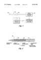
FIG. 3: Is a block diagram illustrating the components of the probe assembly and components used for signal analysis.
FIG. 4: Is a cross-section of a probe having two waveguides.
FIG. 5a: is a cross-section of a probe using a commercial fiber optic connector.
FIG. 5b: is a cross-section of a probe with a clad waveguide.
DESCRIPTION OF THE PREFERRED EMBODIMENT(S)
Referring to FIG. 1, the apparatus of the present invention for detecting ionizing radiation has a first waveguide 100 having a first end 102 and a second end 104, the first waveguide 100 formed of a scintillation material wherein the therapeutic ionizing radiation isotropically generates scintillation light signals within the waveguide 100. The scintillation material may be organic, for example plastic including but not limited to polyvinyltoluene, polystyrene, or mixtures. The plastic may be made with or without wavelength shifters, or inorganic, for example lithium silicate glass, and halide scintillators, for example CsI and/or BaF2.
In a preferred embodiment, the scintillation material is doped with an activator selected from the group consisting of 3 Li6, Ce+++ and combinations thereof. Epithermal neutrons are preferably detected with glass doped with 3 Li6, or with lithium silicate glass doped with light emitting Ce+++ ion.
Cerium-activated 3 Li6 -loaded glasses are fabricated by melting the raw materials under a reducing atmosphere control to prevent the formation of Ce4+. Any reducing atmosphere may be used including but not limited to carbon monoxide mixed with carbon dioxide, preferably a non-explosive mixture of CO and CO2, wet hydrogen (i.e. hydrogen gas with water vapor), preferably saturated hydrogen, argon with 4 vol % hydrogen, and mixtures. The glass melt is quickly cooled by pouring onto a chilled metal plate. This glass can be made into a scintillating fiber form by remelting shards and drawing the fiber from the melt, coating the fresh fiber with an appropriate organic resin and polymerizing the resin on the fiber. Successful fabrication of neutron-sensitive scintillating glass is critically dependent upon control of the oxidation state during the glass melt and fiberizing processes.
When using the present invention to detect the therapeutic dose of gammas and x-rays, the preferred scintillation material depends upon the intensity of radiation to be measured. For large intensity radiation (above about a few rem/minute), the lowest possible Z number should be used to minimize the production of Compton electrons which can cause damage to the patient. A high Z material increases the production of Compton electrons with increasing radiation level. For small intensity radiation (below about a few millirem/hr), the use of high Z number scintillator material improves the detection efficiency. Thus, for maximum detection efficiency, it is preferred to select the highest possible Z material that may be tolerated under a medical protocol. For medium intensity radiation, the choice of scintillator material may be governed by other considerations, for example light output of the scintillator materials and other optical parameters.
Because neutron events produce approximately an order of magnitude more photoelectrons than gamma-ray interactions, a threshold may be chosen to separate neutron events from gamma and other radiation events.
In a preferred embodiment, the first waveguide 100 has a coating 106 encasing the first waveguide 100, thereby forming a probe 108. The coating 106 is preferably a polymer to provide a low activation potential in a radiation field. Polymers specifically preferred are from the group of polysilicones, polypropylenes, polyethylenes and combinations thereof. The first end 109 may be of any shape, but may be tapered as shown for use of the probe 108 as an insertion probe.
The waveguide 100 scintillation material produces light signals that may be transmitted over long distances. Accordingly, light signals must propagate through the scintillation material and any optical cable 110. To achieve long distance transmission of light signals, the light must be fully contained within the scintillation material and the optical cable 100. This containment is achieved in practice via total internal reflection.
Total internal reflection of the light signals of a given wavelength range occurs when two conditions are met: 1) the refractive index of the material surrounding the scintillation material and/or optical cable 100 is smaller than the refractive index of the scintillation material and/or optical cable 100 itself, and 2) the angle of the light signal is smaller than some angle which is determined by the two refractive indices. When these two conditions are met in a waveguiding geometry, i.e., the refractive index of the core is greater than that of the cladding, the radiation will propagate with loss only determined by the absorptive properties of the two materials. In selective circumstances, the cladding may be air, but in most cases, it is necessary and preferred to surround the waveguide 100 scintillation material and the optical cable 110 with a coating or cladding 106, 111 with an appropriate refractive index. In some cases, it may be desirable to provide a cladding 106 that is further surrounded by a protective sheath 112 as shown in FIG. 2.
The first waveguide 100 may be attached to a first optical cable 110 attached to the second end 104 with an optical interface 114 at the contact between the second end 104 and the first optical cable 110.
At the optical interface 114 the light signals will either enter the first optical cable 110 or be reflected at the optical interface 114. The reflection is minimized when the difference between the refractive indices of the scintillator material and the first optical cable 110 is minimized and when the quality of the interface is maximized. The light signal entering the first optical cable 110 will be transmitted without reflective loss only if the ray angles in the second fiber meet the condition for total internal reflection. Therefore, it is important to the successful practice of the invention that the refractive indices of the scintillating material of the waveguide 100 and the first optical cable 110 be properly matched.
The opposite end of the first optical cable 110 is preferably connected to a first port on a scintillation detector (not shown) for receiving optical scintillation from the first waveguide 100. The first optical cable 110 preferably has a protective outer sheath or coating 111.
The scintillation detector may be any scintillation detector which converts the optical signal to an electrical signal including but not limited to photomultiplier tube, and avalance photodiode. When using a photomultiplier tube for measuring neutrons, the photomultiplier tube is preferably operated at a negative high voltage of about 1000 V. The photoelectron signal is pick off the last dynode with a high-speed electronics circuit. The high-speed electronics circuit has a preamplifier connected to a 60-ns integrator which is followed by a discriminating and pulse-counting circuit. The discriminating circuit has a threshold set at least about 1.25 photoelectrons to minimize photomultiplier tube dark count and gamma-ray sensitivity. In a reactor environment, the threshold needs to be set higher for the intense gamma-ray fields therein.
The apparatus of the present invention may be used for determining the relative location with respect to the patient of the therapeutic radiation as well as a dose level. In FIG. 4, in addition to the first waveguide 100, a second waveguide 400 is added. In order to distinguish between scintillation from the first waveguide 100 and the second waveguide 400, the second waveguide 400 is constructed to scintillate a different color light compared to the first waveguide 100. Different color light scintillation is achieved by using different activators, for example a rare earth, (e.g. cerium (Ce+++), erbium) in glasses or crystals; sodium or thallium in alkali halide crystals such as cesium iodide; or different wavelength shifters, for example, 3-hydroxy-flavone. The scintillation detector 300 or 304 must then be able to distinguish between light signals of the different colors.
EXAMPLE 1
An experiment was conducted to demonstrate radiation detection of the present invention. Two probes were constructed as shown in FIG. 5a, 5b. In FIG. 5a, the first waveguide 100 was mounted in a commercial fiber-optic connector 500. The commercial fiber-optic connector 500 has an outer housing 503 that holds two inner sleeves 505 into which are inserted the first waveguide 100 and the first optical cable 110. Epoxy 507 was used to secure the first waveguide 100 and the first optical cable 110 in the inner sleeves 505. In FIG. 5b, the first waveguide 100 with its cladding 502 is glued with silicon into a first glass capillary 504 as a waveguide assembly. The waveguide assembly is glued within a second capillary 506 together with an adjoining commercial clad optical fiber 110. The second capillary 506 extends over the commercial optical fiber 110 and any annular space therebetween is filled with silicon 508.
Fluxes typical of boron neutron capture therapy (about 1019 n/cm2 /sec) and an epicadmium flux have been measured with both probes for periods in excess of an hour. The response of the waveguide 100 was linear with reactor power at the higher (≧10 kW) reactor powers. At lower powers (<10 kW), the residual gamma-ray flux was large enough that the detector response was not linear with reactor power. Even though the pulse-height threshold was not optimized for gamma-ray rejection, the gamma-ray interference was still quite small. The gamma-ray sensitivity would be reduced by more than an order of magnitude by increasing the threshold bias by 50%.
No degradation was observed after leaving a waveguide 100 in the reactor gamma-ray field for 16 hours.
CLOSURE
While a preferred embodiment of the present invention has been shown and described, it will be apparent to those skilled in the art that many changes and modifications may be made without departing from the invention in its broader aspects. The appended claims are therefore intended to cover all such changes and modifications as fall within the true spirit and scope of the invention.

Claims (3)

We claim:
1. A method for making a waveguide for radiation detection, comprising the steps of:
(a) melting a scintillator material and an activator selected from the group consisting of 3 Li6, Ce+++ and combinations thereof in a reducing atmosphere in a doped scintillator melt;
(b) forming the doped scintillator melt into a waveguide by pouring the doped scintillator melt onto a chilled metal plate and forming shards then remelting the shards and drawing the waveguide from the melted shards.
2. The method as recited in claim 1, further comprising the step of coating the waveguide with an organic resin and polymerizing the organic resin.
3. The method as recited in claim 1, wherein said reducing atmosphere is selected from the group consisting of carbon monoxide mixed with carbon dioxide, wet hydrogen, argon with 4 vol % hydrogen, and mixtures.
US08/924,357 1995-05-31 1997-09-05 Method of making a scintillator waveguide Expired - Fee Related US6151769A (en)

Priority Applications (2)

Application Number Priority Date Filing Date Title
US08/924,357 US6151769A (en) 1995-05-31 1997-09-05 Method of making a scintillator waveguide
US09/669,952 US6551231B1 (en) 1995-05-31 2000-09-25 Scintillator waveguide for sensing radiation

Applications Claiming Priority (2)

Application Number Priority Date Filing Date Title
US08/455,586 US5704890A (en) 1995-05-31 1995-05-31 Real time sensor for therapeutic radiation delivery
US08/924,357 US6151769A (en) 1995-05-31 1997-09-05 Method of making a scintillator waveguide

Related Parent Applications (1)

Application Number Title Priority Date Filing Date
US08/455,586 Continuation-In-Part US5704890A (en) 1995-05-31 1995-05-31 Real time sensor for therapeutic radiation delivery

Related Child Applications (1)

Application Number Title Priority Date Filing Date
US09/669,952 Division US6551231B1 (en) 1995-05-31 2000-09-25 Scintillator waveguide for sensing radiation

Publications (1)

Publication Number Publication Date
US6151769A true US6151769A (en) 2000-11-28

Family

ID=46254573

Family Applications (2)

Application Number Title Priority Date Filing Date
US08/924,357 Expired - Fee Related US6151769A (en) 1995-05-31 1997-09-05 Method of making a scintillator waveguide
US09/669,952 Expired - Fee Related US6551231B1 (en) 1995-05-31 2000-09-25 Scintillator waveguide for sensing radiation

Family Applications After (1)

Application Number Title Priority Date Filing Date
US09/669,952 Expired - Fee Related US6551231B1 (en) 1995-05-31 2000-09-25 Scintillator waveguide for sensing radiation

Country Status (1)

Country Link
US (2) US6151769A (en)

Cited By (16)

* Cited by examiner, † Cited by third party
Publication number Priority date Publication date Assignee Title
US6551231B1 (en) * 1995-05-31 2003-04-22 Battelle Memorial Institute Scintillator waveguide for sensing radiation
US6563120B1 (en) 2002-03-06 2003-05-13 Ronan Engineering Co. Flexible radiation detector scintillator
US20030163016A1 (en) * 2002-01-28 2003-08-28 Testardi Louis R. Radiation measurement within the human body
US6713765B2 (en) 2002-03-11 2004-03-30 Galileo Scientific, Inc. Scintillating fiber radiation detector for medical therapy
US20040104347A1 (en) * 2002-12-03 2004-06-03 Bross Alan D. Systems and methods for detecting nuclear radiation in the presence of backgrounds
US20040238751A1 (en) * 2003-05-30 2004-12-02 Penn David G. Coincident neutron detector for providing energy and directional information
US20040252940A1 (en) * 2003-06-16 2004-12-16 Robert Atac Fiber optic light source for display devices
US20040262526A1 (en) * 2003-05-30 2004-12-30 Cti Pet Systems, Inc. Method for fabrication of a detector component using laser technology
US20060138330A1 (en) * 2003-03-28 2006-06-29 Ronan Engineering Company Flexible liquid-filled ionizing radiation scintillator used as a product level detector
US20070092184A1 (en) * 2005-10-26 2007-04-26 Nichia Corporation Optical component, light emitting device, and method for manufacturing optical component
US20100172148A1 (en) * 2009-01-07 2010-07-08 Olympus Corporation Light source device
US20100186173A1 (en) * 2006-07-26 2010-07-29 Farrell Terry C Rescue tool
US20110168899A1 (en) * 2010-01-13 2011-07-14 Andrew Cheshire Detector assemblies and systems having modular housing configuration
WO2014194194A1 (en) * 2013-05-31 2014-12-04 Board Of Regents, The University Of Texas System Large-volume scintillator detector for rapid real-time 3-d dose imaging of advanced radiation therapy modalities
US20160354616A1 (en) * 2008-05-22 2016-12-08 W. Davis Lee Scintillation array apparatus and method of use thereof
US9594184B2 (en) 2015-02-04 2017-03-14 Baker Hughes Incorporated Scintillation detectors and methods for enhanced light gathering

Families Citing this family (9)

* Cited by examiner, † Cited by third party
Publication number Priority date Publication date Assignee Title
US7151261B2 (en) * 2004-01-09 2006-12-19 Crystal Photonics, Incorporated Method of enhancing performance of cerium doped lutetium orthosilicate crystals and crystals produced thereby
US20060049345A1 (en) * 2004-09-09 2006-03-09 Halliburton Energy Services, Inc. Radiation monitoring apparatus, systems, and methods
DE102005018329B4 (en) * 2005-04-20 2008-10-30 Siemens Ag Detector module for X-ray or gamma radiation based on waveguides
JP2009524835A (en) * 2006-01-30 2009-07-02 ザ ユニバーシティ オブ シドニー Fiber optic dosimeter
US20090015814A1 (en) * 2007-07-11 2009-01-15 Carl Zeiss Smt Ag Detector for registering a light intensity, and illumination system equipped with the detector
WO2010057500A1 (en) * 2008-11-21 2010-05-27 Siemens A/S Radiation detector with doped optical guides
US8885986B2 (en) * 2011-05-02 2014-11-11 Radiadyne Llc Small diameter radiation sensor cable
US10365381B1 (en) * 2016-01-22 2019-07-30 Vega Americas, Inc. Flexible nuclear level sensing gauge
FR3089306B1 (en) * 2018-11-30 2021-06-18 Centre Nat Rech Scient Minimally invasive ionizing radiation detector

Family Cites Families (4)

* Cited by examiner, † Cited by third party
Publication number Priority date Publication date Assignee Title
US4788436A (en) * 1986-12-24 1988-11-29 Walter Koechner Radiation sensitive optical fiber and detector
US5588084A (en) * 1995-04-28 1996-12-24 Johnson; Kurtis F. Scintillating optical fibers containing non-uniformly distributed dopants and process for preparing same
US6151769A (en) * 1995-05-31 2000-11-28 Battelle Memorial Institute Method of making a scintillator waveguide
US6360031B1 (en) * 1999-08-24 2002-03-19 Adherent Technologies, Inc. Optical waveguide sensors

Cited By (25)

* Cited by examiner, † Cited by third party
Publication number Priority date Publication date Assignee Title
US6551231B1 (en) * 1995-05-31 2003-04-22 Battelle Memorial Institute Scintillator waveguide for sensing radiation
US20030163016A1 (en) * 2002-01-28 2003-08-28 Testardi Louis R. Radiation measurement within the human body
US6993376B2 (en) 2002-01-28 2006-01-31 Testardi Louis R Radiation measurement within the human body
US6563120B1 (en) 2002-03-06 2003-05-13 Ronan Engineering Co. Flexible radiation detector scintillator
US6713765B2 (en) 2002-03-11 2004-03-30 Galileo Scientific, Inc. Scintillating fiber radiation detector for medical therapy
US20040104347A1 (en) * 2002-12-03 2004-06-03 Bross Alan D. Systems and methods for detecting nuclear radiation in the presence of backgrounds
US6909098B2 (en) * 2002-12-03 2005-06-21 Universities Research Association Inc. Systems and methods for detecting nuclear radiation in the presence of backgrounds
US20060138330A1 (en) * 2003-03-28 2006-06-29 Ronan Engineering Company Flexible liquid-filled ionizing radiation scintillator used as a product level detector
US20040238751A1 (en) * 2003-05-30 2004-12-02 Penn David G. Coincident neutron detector for providing energy and directional information
US8470214B2 (en) * 2003-05-30 2013-06-25 Siemens Medical Solutions Usa, Inc. Method for fabrication of a detector component using laser technology
US20040262526A1 (en) * 2003-05-30 2004-12-30 Cti Pet Systems, Inc. Method for fabrication of a detector component using laser technology
US6989541B2 (en) 2003-05-30 2006-01-24 General Dynamics Advanced Information Systems, Inc. Coincident neutron detector for providing energy and directional information
US7146084B2 (en) 2003-06-16 2006-12-05 Cmc Electronics, Inc. Fiber optic light source for display devices
US20040252940A1 (en) * 2003-06-16 2004-12-16 Robert Atac Fiber optic light source for display devices
US20070092184A1 (en) * 2005-10-26 2007-04-26 Nichia Corporation Optical component, light emitting device, and method for manufacturing optical component
US7600924B2 (en) * 2005-10-26 2009-10-13 Nichia Corporation Optical component, light emitting device, and method for manufacturing optical component
US20100186173A1 (en) * 2006-07-26 2010-07-29 Farrell Terry C Rescue tool
US20160354616A1 (en) * 2008-05-22 2016-12-08 W. Davis Lee Scintillation array apparatus and method of use thereof
US9974978B2 (en) * 2008-05-22 2018-05-22 W. Davis Lee Scintillation array apparatus and method of use thereof
US20100172148A1 (en) * 2009-01-07 2010-07-08 Olympus Corporation Light source device
US8186864B2 (en) * 2009-01-07 2012-05-29 Olympus Corporation Light source device
US20110168899A1 (en) * 2010-01-13 2011-07-14 Andrew Cheshire Detector assemblies and systems having modular housing configuration
WO2014194194A1 (en) * 2013-05-31 2014-12-04 Board Of Regents, The University Of Texas System Large-volume scintillator detector for rapid real-time 3-d dose imaging of advanced radiation therapy modalities
US9625583B2 (en) 2013-05-31 2017-04-18 Board Of Regents, The University Of Texas System Large-volume scintillator detector for rapid real-time 3-D dose imaging of advanced radiation therapy modalities
US9594184B2 (en) 2015-02-04 2017-03-14 Baker Hughes Incorporated Scintillation detectors and methods for enhanced light gathering

Also Published As

Publication number Publication date
US6551231B1 (en) 2003-04-22

Similar Documents

Publication Publication Date Title
US6151769A (en) Method of making a scintillator waveguide
US5704890A (en) Real time sensor for therapeutic radiation delivery
JP3327602B2 (en) Radiation detection optical transmission device
US4598202A (en) Nuclear and pressure sensitive line/perimeter detection system
US9012864B2 (en) Neutron detector
Fernandez et al. Real-time fibre optic radiation dosimeters for nuclear environment monitoring around thermonuclear reactors
JP2001056381A (en) Local dosimeter and medical apparatus using it
JPS60155991A (en) Detection system of neutron or gamma-ray or both neutron andgamma-ray
CA1197024A (en) Radiochromic leuko dye real time dosimeter, one way optical waveguide
Rahman et al. Real-time dosimetry in radiotherapy using tailored optical fibers
Konnoff et al. SSPM based radiation sensing: Preliminary laboratory and clinical results
Bliss et al. Method of making a scintillator waveguide
Takada et al. Application of red and near infrared emission from rare earth ions for radiation measurements based on optical fibers
GB2200984A (en) Fire optic ionizing radiation detector
US11169282B2 (en) Detection apparatus and method
Gaebler Characteristics of fiber optic radiation detectors
Fitzpatrick et al. A large core polymer optical fibre sensor for x-ray dosimetry based on luminescence occurring in the cladding
JPS60164286A (en) Leakage radiation detector
JPH0462031B2 (en)
JPS60159671A (en) Leakage radiation detector
JPS60159670A (en) Leakage radiation detector
JPS59155775A (en) Radiation sensor
Stephenson A Fibre Optic Sensor to Detect Ionising Radiation
JPS6236583A (en) Radiation-measuring apparatus
Jelinek et al. LYSO scintillator with optical fibers to measurement γ radiation

Legal Events

Date Code Title Description
AS Assignment

Owner name: BATTELLE MEMORIAL INSTITUTE, WASHINGTON

Free format text: ASSIGNMENT OF ASSIGNORS INTEREST;ASSIGNORS:BLISS, M.;CRAIG, RA;REEDER, PL;REEL/FRAME:008701/0060

Effective date: 19970829

FEPP Fee payment procedure

Free format text: PAT HOLDER CLAIMS SMALL ENTITY STATUS, ENTITY STATUS SET TO SMALL (ORIGINAL EVENT CODE: LTOS); ENTITY STATUS OF PATENT OWNER: SMALL ENTITY

REFU Refund

Free format text: REFUND - PAYMENT OF MAINTENANCE FEE, 4TH YEAR, LARGE ENTITY (ORIGINAL EVENT CODE: R1551); ENTITY STATUS OF PATENT OWNER: SMALL ENTITY

FPAY Fee payment

Year of fee payment: 4

FPAY Fee payment

Year of fee payment: 8

REMI Maintenance fee reminder mailed
LAPS Lapse for failure to pay maintenance fees
STCH Information on status: patent discontinuation

Free format text: PATENT EXPIRED DUE TO NONPAYMENT OF MAINTENANCE FEES UNDER 37 CFR 1.362

FP Lapsed due to failure to pay maintenance fee

Effective date: 20121128