US6209010B1 - Computer implemented method for wrapping data to an arbitrary path defined by a page description language - Google Patents
Computer implemented method for wrapping data to an arbitrary path defined by a page description language Download PDFInfo
- Publication number
- US6209010B1 US6209010B1 US08/897,467 US89746797A US6209010B1 US 6209010 B1 US6209010 B1 US 6209010B1 US 89746797 A US89746797 A US 89746797A US 6209010 B1 US6209010 B1 US 6209010B1
- Authority
- US
- United States
- Prior art keywords
- path
- data
- wrapping
- text
- bitmap
- Prior art date
- Legal status (The legal status is an assumption and is not a legal conclusion. Google has not performed a legal analysis and makes no representation as to the accuracy of the status listed.)
- Expired - Lifetime
Links
Images


Classifications
-
- G—PHYSICS
- G06—COMPUTING; CALCULATING OR COUNTING
- G06F—ELECTRIC DIGITAL DATA PROCESSING
- G06F40/00—Handling natural language data
- G06F40/10—Text processing
- G06F40/103—Formatting, i.e. changing of presentation of documents
Definitions
- the present invention relates to the high speed printing industry, and more particularly a system and method for flowing variable data into a page description language file in a high speed printing environment.
- Application programs such as word processors, illustrators, and computer-aided design systems are software packages used to create a document (text and graphics) on a computer screen and to simultaneously generate a page description language (“PDL”) specification, which is to be transferred to the printer or to any other type of raster or output device for creating a hard copy or copies of the document.
- PDL page description language
- a PDL specification can be generated by a programmer without the assistance of an application program.
- the printer executes the PDL specification to generate a bitmap of the document, or a raster-data representation of a document, and eventually transfers the bitmap or raster-data to the physical medium.
- a typical PDL language such as PostScript (a registered trademark of Adobe Corporation) defines a page of the document as containing a number of data areas, where each data area contains either graphic or alpha-numeric data.
- Each data area is defined by a “graphic state,” which is a collection of parameters for controlling the representation and appearance of text and graphics.
- the graphic state can include a set of text attributes such as scale-factor, type-font, etc.
- PDL command used to build a graphic state can be: “twenty rotate,” and “/Times-Roman findfont 14 scalefont setfont.”
- Examples of PDL commands used to define the graphic or alpha-numeric data that is displayed in the data area include: 0 0 moveto and (ABC) show.
- the entire group of PDL commands used to define a document is hereinafter referred to as the “PDL specification.”
- each printed document shares a common template and there is at least one area in the template that changes for each printing of the template.
- Typical PDL languages are not designed for high-speed variable data printing because, with PDL languages and PDL interpreters, even if a single item of data in the document changes, an entirely new PDL specification must be created and interpreted. For example, if one-hundred thousand copies of a mass-mailing advertisement were to printed (i.e., each copy of which is identical except for the mailing address), it is typically necessary to generate a new PDL specification for each copy to printed. Hence, to generate one-hundred thousand advertisements, it would be necessary to generate one-hundred thousand PDL specifications, even though each advertisement is virtually the same except for the variable data area. The processing time required to interpret and render one-hundred thousand PDL specifications is enormous, significantly slowing the entire printing system.
- typical PDL languages do not include any text or data flowing capabilities. These features are usually implemented by the application program, and when such an application program flows data (such as text) into a PDL document, the calculations to determine where to place the data are completed prior to the generation to the PDL specification. Accordingly, variable data cannot be flowed into a template document without creating a new PDL specification for each document. Accordingly, there is a need for a high-speed printing operation having the ability to merge variable data into a template defined by a PDL specification; and in particular, having the ability to flow variable data into a template path defined by PDL specification in a high-speed printing operation.
- variable data such as text data, image data, bar code data and the like
- a path of a template defined by a PDL specification in a high-speed printing operation.
- variable data such as text data, image data, bar code data and the like
- a further object of the present invention to provide the ability to generate a plurality of merged bitmaps, which are each essentially a copy of a template, except for at least one portion of the template that contains an arbitrary path. In that path, each merged bitmap can contain a different set of variable data merged into it.
- the template is defined by a page description language, and the page description language only needs to be processed or interpreted once before creating all of the merged bitmaps, thus providing an extremely high-speed variable data printing operation.
- the computer implemented method for flowing data into an arbitrary path defined by a page description language specification generally comprises the steps of: processing (interpreting) the PDL specification to produce a template; designating a path defined in the PDL specification as a wrapping path; associating a block of variable data with the wrapping path; and merging variable data, according to the path boundary and according to a predefined flow rule, into a copy of the template.
- the method of the present invention is accomplished by executing a control task in conjunction with a PDL interpreter program.
- the control task generates a template display list based upon the PDL commands in the PDL specification.
- the display list includes a plurality of rendering commands, where each rendering command designates a particular data area or object to be rendered, the graphics state to be applied to the data area and the offset address at which the rendered object, if any, in the data area is to be overwritten onto the final bit map.
- the graphic states for each data area are set forth in the PDL specification, and pertain to the print attributes that describe how particular graphic or alpha-numeric data is to appear on the printed page. These attributes can include the size, font, position, orientation, location, and the like.
- the control task monitors the data areas defined by the PDL specification to watch for variable data paths defined by the PDL code. If the control task identifies a path as being a variable data path, it reserves the graphic states associated with that variable data path in a cache or memory, and then moves on to the next data area defined in the PDL specification, preferably without allowing the path data to be added to the template display list.
- the control task saves the template display list in memory without dispatching a bitmap of the template to the printer.
- a merge task is initiated which accesses a variable data record from a merge file; associates the variable data record to a particular variable data path; creates representations of the variable data, such as rendering commands according to the reserved graphic states pertaining to that particular variable data path, according to the boundary of the particular variable data path and according to a predefined flow rule; and then generates a merged bitmap by processing the template display list and the variable data rendering commands. The final merged bitmap that may then be dispatched to the printer.
- This merge task is repeated for each variable data record in the merge file associated with that particular variable data path to create a plurality of the merged bitmaps.
- the PDL specification of the template need only be interpreted once, saving significant processing time for the variable printing operation, because the reserved graphic states may be utilized over and over again to create the flowed data bitmap for each variable data record contained in the merge file.
- control task identifies a particular PDL path defined in the PDL specification as being unique, i.e., as being identified as a wrapping path. This is accomplished by providing a text command in the PDL specification that defines one or more characters that are recognized by the control task as being special characters, as opposed to merely being characters that are to be included on the printed page.
- the control task monitors all text strings defined by the PDL specification for such special characters, and responsive to a detection of the special character in the text string defined by the text command, the control task identifies the path command that has a predetermined relationship with the text command in the PDL specification. This predetermined relationship can be satisfied by the first path command to follow the text command in the PDL specification or by the path command that is “grouped” with the text command in the PDL specification.
- the characters “ ⁇ ” and “>>” are used as part of a special text string to define an area as a variable data area. And if that special text string also includes the string wrap then the control task will recognize that the very next path command appearing in the PDL specification will be a unique path, in this case a path for flowing variable text bitmaps into.
- FIG. 1 is a is a schematic, block-diagram representation of a high-speed printing system according to the present invention
- FIG. 2 is an example of a job ticket file for use with the present invention
- FIG. 3 is an example of a merge file for use with the present invention.
- FIG. 4 is a graphical representation of data contained in a PDL specification for use with the present invention.
- FIG. 5 is a graphical representation of a process step of the present invention operating on data contained in the PDL specification of FIG. 4;
- FIG. 6 is a graphical representation of a process step of the present invention following the process step of FIG. 5;
- FIG. 7 is a graphical representation of a process step of the present invention following the process steps of FIGS. 5 and 6;
- FIG. 8 is a graphical representation of a process step of the present invention following the process steps of FIGS. 5 and 6;
- FIG. 9 is an example of a merged document created by the process and system of the present invention.
- FIG. 10 is an example of a merged document created by the process and system of the present invention.
- FIG. 11 is a flow chart representation of a process of the present invention.
- FIG. 12 is an example of a merged document created by the process and system of the present invention.
- FIG. 13 is an example of a merged document created by the process and system of the present invention.
- a system for performing the method of the present invention includes a printer controller 10 having access to a job ticket file 12 , a page description language (“PDL”) file 14 , a source of variable data such as a merge file 16 , and an optional printer configuration file 18 .
- the system also contains an operator control terminal 20 for providing operator controls such as indicating the name and location (file-path) of the job ticket file 12 for the specific print job.
- the job ticket file 12 contains the guidelines for the print job which can include the names and locations of the PDL file(s) 14 , the merge file(s) 16 , the configuration file(s) 18 , etc.; and may also include special instructions pertaining to features such as data wrapping, described below.
- the PDL file 14 is preferably a PostScript specification created by an application program, such as a word processor, illustrator, or computer-aided design system.
- the merge file 16 contains platform independent data, such as text data, image data, bar-code data and the like, which is to be merged into a template bitmap defined by the PDL file during the merging task, as will be described in detail below.
- the configuration file 18 defines the print engines and post processing equipment and other options to be executed.
- the location and name of the job ticket file 12 is specified by the operator using the operator control terminal 20 .
- the printer controller 10 retrieves the job ticket file 12 and then retrieves the PDL files 14 and merge files 16 that are specified in the job ticket file.
- the controller 10 initiates a control task 22 in conjunction with a page description code interpreter program.
- the control task interprets the PDL specification from the PDL file 14 and monitors data areas defined in the PDL specification to watch for areas defined by the specification to become variable data areas. If the control task identifies a data area as being a variable data area, it reserves the graphic states 23 of that variable data area in memory 24 and then moves on to the next data area defined by the PDL specification, usually without allowing any data defined by the variable data area to be added to the template bitmap. Preferably, the control task 22 will also create a font cache (an entire set of character bitmaps generated according to the reserved graphic states) for the reserved graphic states, which will be linked to the reserved graphic states in memory 24 . Once the control task completes its processing of the PDL specification, the control task saves the template bitmap 25 in memory 26 .
- the control task 22 may also create a template display list 25 of static data defined by the PDL file 14 .
- the display list 25 will include a plurality of rendering commands, where each rendering command designates a particular static data area or object to be rendered, the graphics state to be applied to the static data area and the offset address at which the rendered object, if any, in the static data area is to be overwritten onto the final bit map.
- the graphic states for each data area are set forth in the PDL specification, and pertain to the print attributes that describe how particular graphic or alpha-numeric data is to appear on the printed page.
- a merge task 28 having access to the variable data records 17 from the merge file 16 , is executed to apply the reserved graphics states 23 and associated font cache to the variable data records 17 , creating rendering commands for that variable data record as defined by the graphic states.
- the merge task 28 retrieves a copy 25 ′ of the template display list 25 from the memory 26 and merges the variable data rendering commands with the template display list to create a merged display list 30 .
- the controller 10 performs a rendering task 32 to render the merged display list 30 into a plurality of bitmap bands 34 for dispatching to at least one print engine 36 .
- a method for performing the above control task and merge task is described in U.S. patent application Ser. No. 08/373,582 filed Jan. 17, 1995 and entitled “Method of Utilizing Variable Data Fields with a Page Description Language,” the disclosure of which is incorporated herein by reference.
- a method and a system architecture for performing the above merging, banding and dispatching operations are respectively described in U.S. Pat. No. 5,594,860 and U.S. patent application Ser. No. 08/558,007, filed Nov. 13, 1995, and entitled “System Architecture for Processing and Transporting a Pagemap or Bitmap Data to a Raster Print Engine,” the disclosures of which is also incorporated herein by reference.
- the job ticket file 12 can contain a file location statement 38 for determining the location and name of the PDL file, and can contain a file location statement 40 for determining the location and name of the merge file.
- the job ticket file 12 can also contain a descriptive name of a wrapping path 42 , in this case, named “Shape,” for identifying a name of a wrapping path in the PDL file that is to have variable data flowed into it during the merge task.
- the variable data to be flowed into the wrapping path text data in this case, will be taken from the file designated by the file location statement 40 of the merge file.
- the merge file is named “info.text.”
- the group header 44 “[Wrap]” indicates that the group is defining a wrapping path.
- a second group header 46 “[Shape]” can be thereafter defined in the job ticket file to provide information about the wrap path; such as defining the fill rule 48 to be used in the wrapping operation, and such as defining a path drawing rule 50 , i.e., whether the path is to be drawn in the final rendered image.
- Other definable wrapping commands for the particular path “Shape” can include defining the top, bottom or side margins, defining the justification, setting the number of paths to flow the data into, defining an overflow path, etc.
- the merge file 16 is a platform-independent data file that contains the “variable” data to be merged into the path defined in the PDL specification.
- the merge file can contain a field name 52 , corresponding to a field name that will be defined in the PDL specification, which is associated with a particular variable data path.
- the merge file will also contain a number of variable data blocks 54 , text blocks in this case, corresponding to the field name 52 .
- One variable data block 54 will be merged into the variable data path, defined in the PDL specification, at a time.
- the designer will utilize an application program to create a document containing a path 56 and attribute data, such as an attribute string 58 , to be associated with the path 56 .
- the application program will then be directed to create a PDL specification of the document by the designer.
- the attribute string 58 contains a field name 60 surrounded by special characters, “ ⁇ ” and “>>”, a wrap attribute command string 62 , and a path identifier 64 .
- the PDL specification generated by the application program will include the graphic states of the attribute string 58 . These graphic states can include the font size (i.e., 10 point), the type-font (i.e., Script) the orientation (i.e., angled upwardly at 50°) and the like.
- control task 22 will execute a PDL interpreter program to interpret the PDL specification created by the application program to generate a template bitmap 25 of the document, and to also monitor for any variable data paths defined in the PDL specification.
- the control task 22 monitors for variable data areas defined by the PDL specification by monitoring for special characters in the text strings defined by text commands in the PDL specification. As shown in FIG. 4, the special characters “ ⁇ ” and “>>” surround the field name 60 .
- the control task upon identifying the special characters in the text command for the attribute string will thus know that the attribute string 58 is defining a variable data area, and is not merely defining a text string to appear on the printed page (the attribute string will not appear on the final printed page unless the control task is directed to by the job ticket file).
- the field name 60 surrounded by the special characters identifies the associated field name 52 present in the merge file 16 .
- the control task will also monitor for the wrap string 62 within the attribute string, which also includes the path identifier string 64 associated therewith. If found, the control task will know that a path defined in the PDL specification that has a predetermined relationship with the text command for the attribute string will be a wrapping path, where the wrapping path has the wrapping attributes defined in the job ticket file 12 for the particular group header 44 and descriptive name of a path 42 matching the path identifier string 64 set forth in the attribute string 58 .
- the predetermined relationship is satisfied by the first path command to follow the text command for the attribute string in the PDL specification.
- This can be accomplished by using the application program to sequentially type the attribute string 58 and then draw the path 56 , such that the path command will be the first path command to follow the text command in the PDL specification created by the application program.
- the predetermined relationship can be satisfied by the path command that is “grouped” with the text command for the attribute string in the PDL specification. This can be accomplished by using a “GROUP” tool as provided by many application programs to group the attribute string 58 and path 56 together. It will be apparent to one of ordinary skill in the art that there are many similar predetermined relationships available between the text command for the attribute string and the path command for the wrapping path that can be established in the PDL specification, all of which fall within the scope of the present invention.
- the control task 22 will match the wrap attribute command string 62 and path identifier 64 with the group header 44 and descriptive name of the path 42 defined in the job ticket file 12 .
- the control task will save the graphic states 23 of the attribute string 58 in memory.
- the control task may also create a font cache according to the graphic states 23 , and store the font cache along with the graphic states in memory 24 .
- the control task will also save the field name 60 along with the graphic states 23 in memory so that the particular graphic states can be matched to the blocks of text data in the merge file 16 under the matching field name 52 , as will be described below.
- the merge task 28 will apply these graphic states 23 and associated font cache to the variable data 54 prior to merging and flowing the variable data into the path 56 .
- control task 22 Once the control task 22 has identified the path as being a variable data path, and has reserved the graphic states 23 of the attribute string 58 associated with the path in memory 24 , the control task 22 advances to the next data area in the PDL specification, preferably without allowing the attribute string data or the path to be added to the template display list 25 stored in memory 26 . And once the PDL interpreter program has completed interpreting the PDL specification, the control task 22 then passes authority to the merge task 28 .
- the merge task 28 first accesses a set of the saved graphic states 23 and identifies the field name 60 associated with these graphic states.
- the merge task 28 then accesses the merge file 16 and searches the merge file for a field name 52 matching the field name 60 associated with the graphic states.
- the merge task then accesses a variable data block 54 associated with the field name 52 and then generates rendering commands for the variable data block according to the graphic states 23 , the predefined flow rule 48 and the boundary of the path 56 .
- the predefined flow rule 48 may or may not be defined by the job ticket file 12 . Accordingly, when the rendering command is executed the bit map data defined by the rendering command will flow within the path 56 according to a predefined flow rule.
- a method for merging and flowing the variable text data into the path 56 is as follows: as indicated in step 100 and illustrated in FIG. 5, preferably the control task will first “flatten” the path, which involves breaking the complex path 56 (which may contain ellipses and curves) into a series of simple straight lines 64 (i.e., converting the path into a series of “move to” and “line to” commands). Each straight line 64 will comprise a particular portion of a boundary 65 , into which the variable data is to be positioned. Alternatively, it is within the scope of the present invention to have the path 56 itself define the boundary into which the variable data is to be positioned.
- the extent of the boundary may also be defined, in part, by the designation of margins, or the creation of additional paths, etc.
- a horizontal axis 67 of a coordinate system 69 will be aligned with the attribute string 58 .
- a new equivalent boundary 65 ′ is created, whose coordinates are those of the original boundary 65 , but rotated into the same coordinate system 69 as the attribute string 58 (for example, as shown in FIG. 5, the attribute string 58 is rotated a negative 50° in the document, and therefore, in FIG. 6 the boundary 65 ′ is rotated by a positive 50°).
- the stored graphic states 23 are applied to a variable data block 54 to be merged into the boundary 65 ′ so as to calculate the dimensions of a plurality of word bitmaps, the word bitmaps being defined by a collection of characters separated from the rest of the data by white space characters (e.g., a space, tab, new line, etc.).
- the dimensions of paragraphs can be calculated by defining a paragraph as a collection of word bitmaps separated from other paragraphs by “new line” characters. Assuming that the text flow direction will be from top to bottom and left to right, as indicated in step 108 and as illustrated in FIGS.
- the “top” or highest point 66 of the path 65 ′ is determined and a top margin 68 is applied to the boundary 65 ′ by measuring a distance downward from the highest point 66 of the boundary.
- the top margin 68 can be pre-defined, defined in the job ticket file 12 , or by any other sufficient means.
- a rectangular insertion area 70 is defined, having a vertical height corresponding to the calculated vertical height of the bitmap representation of the first word (the point size of the text) to be flowed into the boundary 65 ′, and having a top horizontal border 72 abutting the top margin 68 .
- this insertion area 70 will be overlaid onto the entire boundary 65 ′ at that present vertical level to establish at least one intersection point 74 .
- only those areas between adjacent intersection points 74 will be considered valid candidates for receiving the bitmap representations of the text data.
- intersection points there are more than two intersection points present within insertion area, then the particular flow rule being utilized will determine between which of the intersection points that the bitmap representations of the text data will be inserted. As illustrated in FIGS. 7 and 8, when only two intersection points are established, the bitmap representations of the text data will typically be inserted therebetween.
- left and right margins will then be measured inwardly from each of the intersection points 74 to define left and right borders 77 within the insertion area 70 . Between the left and right borders 77 , therefore, is defined a text placement area 78 for merging the bitmap representations of the text data therein.
- the left and right margins 76 can be pre-defined, defined in the job ticket file 12 , or determined by any other sufficient means.
- the rendering commands to create the bitmap representations of a word of the text data as merged into the text placement area are created and added to the display list 25 , depending upon whether the calculated width of the bitmap is equal to or less than the available width calculated to remain in the text placement area.
- the rendering commands will define the proper orientation of the bitmap representation of the word rotated back into the original orientation of the attribute string 58 .
- bitmap representations of the words “in” and “a” were able to fit therewithin, however, the bitmap representation of the word “world” was too wide for the remaining width. Accordingly, in the final merged bitmap only the bitmaps representing the words “in” and “a” will be rendered into the first text placement area 78 . If no word bitmaps are capable of fitting within the text placement area, then the area is left blank.
- a line-spacing 79 is measured below the present insertion area and then the next rectangular insertion area 80 is created and overlaid onto the boundary 65 ′ below the line-spacing 79 in the same manner as defined above for the first rectangular insertion area 70 .
- the merging process for this particular boundary and text block is finished as shown in step 124 . If the insertion area does not extend below the lowest point of the boundary and there are more bitmaps representing words to insert, then the process returns to step 114 , described above.
- steps 114 - 122 will be repeated thereafter until step 124 is reached.
- bitmaps representing the words “world” and “of” were able to be rendered into the second rectangular insertion area 80 and bitmaps representing the words “interactive,” “media” and “and” were able to rendered into third rectangular insertion area 82 .
- step 122 the merge task will then search for additional variable data areas or variable data paths in which to merge variable data blocks. If no more of such variable data areas or variable data paths exist for the particular document, then the merged display list 30 is transferred to the rendering task 32 , as described above, to generate the bitmap bands 34 for printing.
- FIG. 9 illustrates the entire block of text 54 from the merge file 16 formatted according to the above process and merged into the path 56 to create a first finished document 84 .
- FIG. 10 illustrates the appearance of the next block of text 54 ′ from the merge file 16 formatted according to the above process and merged into the path 56 to create a second finished document 86 .
- the height of the rectangular insertion area is determined by the dimensions calculated for the first word bitmap. And if, for whatever reason, a next word bitmap is calculated to be higher than the first or previous word bitmap, and higher than all other word bitmaps inserted thus far into a particular text placement area, then the entire rectangular insertion area is thrown out, and steps 116 and 118 are repeated again for the higher rectangular insertion area generated according to this higher word bitmap.
- the merge task can mark the path intersections 74 as “positive,” “negative” or “neutral” based upon whether the path enters and leaves from the top or the bottom of the insertion area, or whether it enters and exits the insertion area from the same direction. All of the available fill rules will be apparent to one of ordinary skill in the art, and are thus within the scope of the present invention.
- text flowing into the boundary 65 ′ will continue until it is determined that there are no more word bitmaps to flow into the boundary or until it is determined that there is no more text areas available to flow the word bitmaps into. In the case of the latter, it is within the scope of the invention to define a path as an “overflow” path for continuing the flowing of the text therein, until this overflow path runs out of room. This overflowing process can continue until once again it is determined that there are no more text areas to flow text into. Text can also flowed into more than one path at a time.
- the two flow paths are the circle and square paths, designated as numerals 88 and 90 , respectively; then the two paths essentially comprise one boundary, and text will flow directly from the circle path 88 into the square path 90 .
- the 2nd through 8th lines of text flow from the circle path 88 directly into the square path 90 .
- the flowing operation stops because the area within the two flow paths have been used up. Accordingly, as illustrated in FIG. 13, if an “overflow path” is designated in the job ticket file to be the triangle path 92 , the text flowing will continue into the triangle path 92 until there is no more text to be merged or until the path runs out of additional room.
- the present invention provides capability of identifying particular paths defined in a page description language as data flowing paths, and provides the capability for flowing data within such paths.
- the present invention allows the user to specify margin, paragraph formatting, fill rules, and justification parameters on a path by path basis.
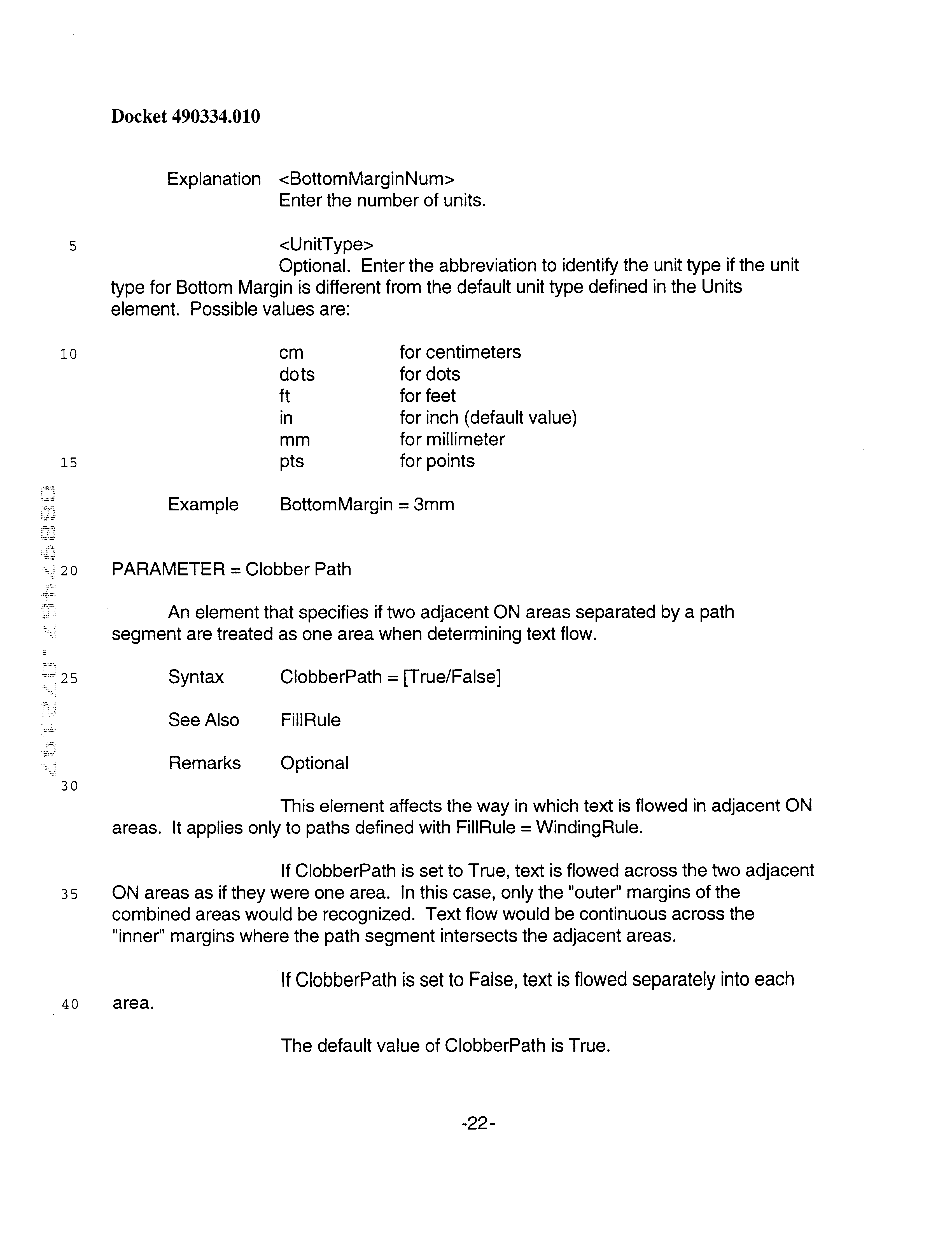
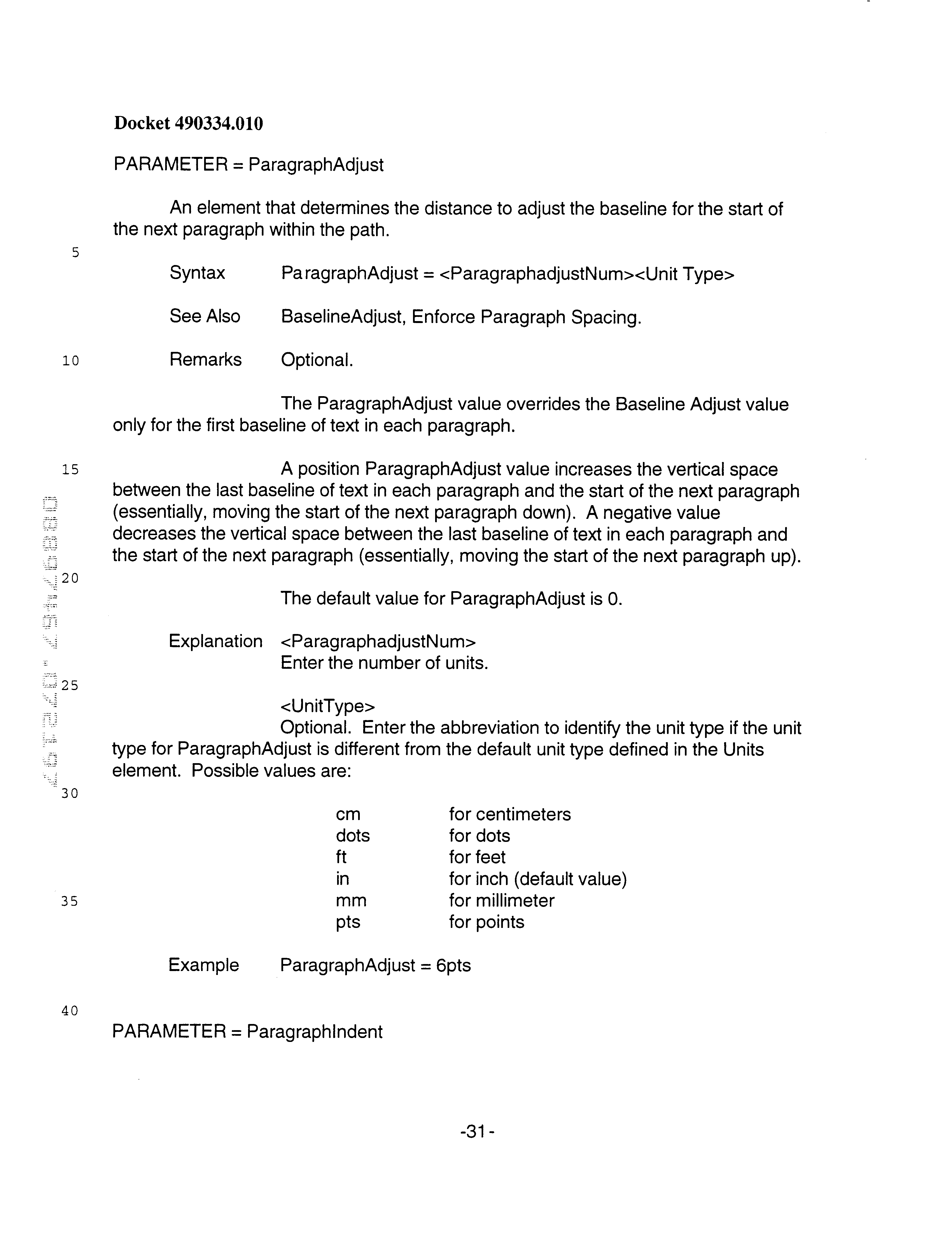
- the following appendix provides a preferred compilation of text wrapping commands and parameter definitions that can be specified in the job ticket file 12 .
- Each entry provides the particular command header, the syntax for the command, any relevant remarks for the use of the command, examples, etc.
Abstract
Description


Claims (20)
Priority Applications (6)
| Application Number | Priority Date | Filing Date | Title |
|---|---|---|---|
| US08/897,467 US6209010B1 (en) | 1997-07-18 | 1997-07-18 | Computer implemented method for wrapping data to an arbitrary path defined by a page description language |
| US09/818,665 US6487568B1 (en) | 1997-07-18 | 2001-03-27 | Method and system for flowing data to an arbitrary path defined by a page description language |
| US10/233,263 US6599325B2 (en) | 1997-07-18 | 2002-08-30 | Method and system for flowing data to an arbitrary path defined by a page description language |
| US10/629,338 US20050076001A1 (en) | 1997-07-18 | 2003-07-29 | Method and system for flowing data to an arbitrary path defined by a page description language |
| US11/153,256 US20050286065A1 (en) | 1997-07-18 | 2005-06-15 | Method and system for flowing data to an arbitrary path defined by a page description language |
| US11/226,850 US7302438B1 (en) | 1997-07-18 | 2005-09-14 | Method and system for flowing data to an arbitrary path defined by a page description language |
Applications Claiming Priority (1)
| Application Number | Priority Date | Filing Date | Title |
|---|---|---|---|
| US08/897,467 US6209010B1 (en) | 1997-07-18 | 1997-07-18 | Computer implemented method for wrapping data to an arbitrary path defined by a page description language |
Related Child Applications (1)
| Application Number | Title | Priority Date | Filing Date |
|---|---|---|---|
| US09/818,665 Continuation-In-Part US6487568B1 (en) | 1997-07-18 | 2001-03-27 | Method and system for flowing data to an arbitrary path defined by a page description language |
Publications (1)
| Publication Number | Publication Date |
|---|---|
| US6209010B1 true US6209010B1 (en) | 2001-03-27 |
Family
ID=25407940
Family Applications (1)
| Application Number | Title | Priority Date | Filing Date |
|---|---|---|---|
| US08/897,467 Expired - Lifetime US6209010B1 (en) | 1997-07-18 | 1997-07-18 | Computer implemented method for wrapping data to an arbitrary path defined by a page description language |
Country Status (1)
| Country | Link |
|---|---|
| US (1) | US6209010B1 (en) |
Cited By (32)
| Publication number | Priority date | Publication date | Assignee | Title |
|---|---|---|---|---|
| US20010051964A1 (en) * | 1995-06-07 | 2001-12-13 | R.R. Donnelley & Sons Company | Imposition process and apparatus for variable imaging system |
| US20020049702A1 (en) * | 2000-02-03 | 2002-04-25 | Jacob Aizikowitz | System and method for creating customized documents for cross media publishing |
| US20030038972A1 (en) * | 2002-09-10 | 2003-02-27 | Benstein Thomas A | Method and system for preparing printed matter |
| US6547831B1 (en) * | 1999-05-26 | 2003-04-15 | Todd Kueny | Method of generating documents having variable data fields |
| US20030189727A1 (en) * | 2002-04-09 | 2003-10-09 | Nexpress Solutions Llc | Method and apparatus for using fields of data to organize variable data print jobs |
| US20030189725A1 (en) * | 2002-04-09 | 2003-10-09 | Nexpress Solutions Llc | Variable data printing using family groupings |
| US20030189724A1 (en) * | 2002-04-09 | 2003-10-09 | Nexpress Solutions Llc | Variable data printing using variants |
| US20030189726A1 (en) * | 2002-04-09 | 2003-10-09 | Nexpress Solutions Llc | Variable data printing dynamic imposition template |
| US20030237054A1 (en) * | 2002-06-21 | 2003-12-25 | Nexpress Solutions Llc | Concept for automated scatter proofing of content elements used in personalized print jobs |
| US20040066527A1 (en) * | 2002-10-02 | 2004-04-08 | Nexpress Solutions Llc | Finish verification in printing |
| US20040130752A1 (en) * | 1995-01-18 | 2004-07-08 | Tesseron, Ltd. | Method of utilizing variable data fields with a page description language |
| US6765595B2 (en) | 2001-08-16 | 2004-07-20 | International Business Machines Corporation | Dual mode data field |
| US20050278614A1 (en) * | 2000-02-03 | 2005-12-15 | Xmpie Inc. | System and method for efficient production of dynamic documents |
| US20050286065A1 (en) * | 1997-07-18 | 2005-12-29 | Gauthier Forrest P | Method and system for flowing data to an arbitrary path defined by a page description language |
| US20060044614A1 (en) * | 2002-08-28 | 2006-03-02 | Amit Cohen | Apparatus and method for processing variable print documents |
| US20070195095A1 (en) * | 2006-02-17 | 2007-08-23 | Microsoft Corporation | Applying effects to a merged text path |
| US20080018935A1 (en) * | 1995-01-18 | 2008-01-24 | Gauthier Forrest P | Method and system for merging variable text and images into bitmaps defined by a page description language |
| US20080144108A1 (en) * | 2002-08-28 | 2008-06-19 | Gal Bezalel Kahana | System and method for processing variable print documents |
| US20080313550A1 (en) * | 2007-06-15 | 2008-12-18 | Fujitsu Limited | RECORDING MEDIUM ON WHICH Web CONFERENCE SUPPORT PROGRAM IS RECORDED AND Web CONFERENCE SUPPORT APPARATUS |
| US20090150394A1 (en) * | 2007-12-06 | 2009-06-11 | Microsoft Corporation | Document Merge |
| US20090157811A1 (en) * | 2007-12-14 | 2009-06-18 | Microsoft Corporation | Collaborative Authoring Modes |
| US20090271696A1 (en) * | 2008-04-28 | 2009-10-29 | Microsoft Corporation | Conflict Resolution |
| US20090282462A1 (en) * | 2008-05-08 | 2009-11-12 | Microsoft Corporation | Controlling Access to Documents Using File Locks |
| US20090327294A1 (en) * | 2008-06-25 | 2009-12-31 | Microsoft Corporation | Structured Coauthoring |
| US20100131836A1 (en) * | 2008-11-24 | 2010-05-27 | Microsoft Corporation | User-authored notes on shared documents |
| US20100281074A1 (en) * | 2009-04-30 | 2010-11-04 | Microsoft Corporation | Fast Merge Support for Legacy Documents |
| US7949945B2 (en) | 2000-05-03 | 2011-05-24 | Rr Donnelley & Sons | Variable text processing for an electronic press |
| US20110184906A1 (en) * | 2007-11-09 | 2011-07-28 | Microsoft Corporation | Client Side Locking |
| US8301588B2 (en) | 2008-03-07 | 2012-10-30 | Microsoft Corporation | Data storage for file updates |
| US20130250325A1 (en) * | 2012-03-21 | 2013-09-26 | Claudia Alimpich | Insertion of job tickets into job tickets of another language |
| US8793572B2 (en) * | 2011-06-30 | 2014-07-29 | Konica Minolta Laboratory U.S.A., Inc. | Positioning graphical objects within previously formatted text |
| US8825594B2 (en) | 2008-05-08 | 2014-09-02 | Microsoft Corporation | Caching infrastructure |
Citations (19)
| Publication number | Priority date | Publication date | Assignee | Title |
|---|---|---|---|---|
| US5103490A (en) | 1990-06-13 | 1992-04-07 | National Computer Systems, Inc. | Method and apparatus for storing and merging multiple optically scanned images |
| US5134669A (en) | 1990-06-13 | 1992-07-28 | National Computer Systems | Image processing system for documentary data |
| US5157765A (en) | 1989-11-15 | 1992-10-20 | International Business Machines Corporation | Method and apparatus for pipelined parallel rasterization |
| US5202206A (en) | 1991-10-04 | 1993-04-13 | Xerox Corporation | Process for simultaneous printing of fixed data and variable data |
| US5208906A (en) | 1988-12-30 | 1993-05-04 | Chipsoft Ca, Corp. | Method and apparatus for representing bordered areas of a generic form with records |
| US5231698A (en) | 1991-03-20 | 1993-07-27 | Forcier Mitchell D | Script/binary-encoded-character processing method and system |
| US5291243A (en) | 1993-02-05 | 1994-03-01 | Xerox Corporation | System for electronically printing plural-color tamper-resistant documents |
| US5459819A (en) | 1993-09-24 | 1995-10-17 | Eastman Kodak Company | System for custom imprinting a variety of articles with images obtained from a variety of different sources |
| US5459826A (en) | 1990-05-25 | 1995-10-17 | Archibald; Delbert M. | System and method for preparing text and pictorial materials for printing using predetermined coding and merging regimen |
| US5467448A (en) | 1991-05-10 | 1995-11-14 | Claris Corporation | Text formatting by the direct selection of borders in an editing display |
| US5506697A (en) | 1990-01-05 | 1996-04-09 | Symbol Technologies, Inc. | Apparatus for processing human-readable and machine-readable documents |
| US5539529A (en) | 1994-04-04 | 1996-07-23 | Merchant; Zaffer S. | Facsimile communication with selective call receivers |
| US5542052A (en) * | 1991-03-04 | 1996-07-30 | Adobe Systems Incorporated | Applying traps to a printed page specified in a page description language format |
| US5600768A (en) * | 1995-06-06 | 1997-02-04 | Apple Computer, Inc. | Image generation with dynamically consolidated list of image data |
| US5611024A (en) * | 1992-08-28 | 1997-03-11 | Compaq Computer Corporation | Data compression of bit map images |
| US5671345A (en) * | 1995-06-06 | 1997-09-23 | Apple Computer, Inc. | System and method for intercepting and reconstructing graphics management tool marking instructions |
| US5754750A (en) * | 1990-08-08 | 1998-05-19 | Peerless Systems Corporation | Method and apparatus for displaying a page with graphics information on a continuous synchronous raster output device |
| US5841420A (en) * | 1995-08-18 | 1998-11-24 | International Business Machines Corporation | Method and system in a data processing system windowing environment for displaying previously obscured information |
| US5926185A (en) * | 1996-05-03 | 1999-07-20 | Barco Graphics N.V. | Method for processing a set of page description language commands to reduce complexity |
-
1997
- 1997-07-18 US US08/897,467 patent/US6209010B1/en not_active Expired - Lifetime
Patent Citations (19)
| Publication number | Priority date | Publication date | Assignee | Title |
|---|---|---|---|---|
| US5208906A (en) | 1988-12-30 | 1993-05-04 | Chipsoft Ca, Corp. | Method and apparatus for representing bordered areas of a generic form with records |
| US5157765A (en) | 1989-11-15 | 1992-10-20 | International Business Machines Corporation | Method and apparatus for pipelined parallel rasterization |
| US5506697A (en) | 1990-01-05 | 1996-04-09 | Symbol Technologies, Inc. | Apparatus for processing human-readable and machine-readable documents |
| US5459826A (en) | 1990-05-25 | 1995-10-17 | Archibald; Delbert M. | System and method for preparing text and pictorial materials for printing using predetermined coding and merging regimen |
| US5103490A (en) | 1990-06-13 | 1992-04-07 | National Computer Systems, Inc. | Method and apparatus for storing and merging multiple optically scanned images |
| US5134669A (en) | 1990-06-13 | 1992-07-28 | National Computer Systems | Image processing system for documentary data |
| US5754750A (en) * | 1990-08-08 | 1998-05-19 | Peerless Systems Corporation | Method and apparatus for displaying a page with graphics information on a continuous synchronous raster output device |
| US5542052A (en) * | 1991-03-04 | 1996-07-30 | Adobe Systems Incorporated | Applying traps to a printed page specified in a page description language format |
| US5231698A (en) | 1991-03-20 | 1993-07-27 | Forcier Mitchell D | Script/binary-encoded-character processing method and system |
| US5467448A (en) | 1991-05-10 | 1995-11-14 | Claris Corporation | Text formatting by the direct selection of borders in an editing display |
| US5202206A (en) | 1991-10-04 | 1993-04-13 | Xerox Corporation | Process for simultaneous printing of fixed data and variable data |
| US5611024A (en) * | 1992-08-28 | 1997-03-11 | Compaq Computer Corporation | Data compression of bit map images |
| US5291243A (en) | 1993-02-05 | 1994-03-01 | Xerox Corporation | System for electronically printing plural-color tamper-resistant documents |
| US5459819A (en) | 1993-09-24 | 1995-10-17 | Eastman Kodak Company | System for custom imprinting a variety of articles with images obtained from a variety of different sources |
| US5539529A (en) | 1994-04-04 | 1996-07-23 | Merchant; Zaffer S. | Facsimile communication with selective call receivers |
| US5600768A (en) * | 1995-06-06 | 1997-02-04 | Apple Computer, Inc. | Image generation with dynamically consolidated list of image data |
| US5671345A (en) * | 1995-06-06 | 1997-09-23 | Apple Computer, Inc. | System and method for intercepting and reconstructing graphics management tool marking instructions |
| US5841420A (en) * | 1995-08-18 | 1998-11-24 | International Business Machines Corporation | Method and system in a data processing system windowing environment for displaying previously obscured information |
| US5926185A (en) * | 1996-05-03 | 1999-07-20 | Barco Graphics N.V. | Method for processing a set of page description language commands to reduce complexity |
Non-Patent Citations (3)
| Title |
|---|
| IDG InfoWorld, Oct. 9, 1995, Review, p. 91. |
| IDS InfoWorld, Mar. 20, 1995, Product Reviews; Desktop publishing software; p. 92. |
| InfoWorld, May 9, 1994, Review; p. 98. |
Cited By (57)
| Publication number | Priority date | Publication date | Assignee | Title |
|---|---|---|---|---|
| US20050185212A1 (en) * | 1995-01-18 | 2005-08-25 | Gauthier Forrest P. | Method of utilizing variable data fields with a page description language |
| US20080018935A1 (en) * | 1995-01-18 | 2008-01-24 | Gauthier Forrest P | Method and system for merging variable text and images into bitmaps defined by a page description language |
| US20040130752A1 (en) * | 1995-01-18 | 2004-07-08 | Tesseron, Ltd. | Method of utilizing variable data fields with a page description language |
| US20040141197A1 (en) * | 1995-01-18 | 2004-07-22 | Tesseron, Ltd. | Method of utilizing variable data fields with a page description language |
| US20040216046A1 (en) * | 1995-06-07 | 2004-10-28 | R.R. Donnelley & Sons Company | Imposition process and apparatus for variable imaging system |
| US20010051964A1 (en) * | 1995-06-07 | 2001-12-13 | R.R. Donnelley & Sons Company | Imposition process and apparatus for variable imaging system |
| US20040141207A1 (en) * | 1995-06-07 | 2004-07-22 | R.R. Donnelley & Sons Company | Imposition process and apparatus for variable imaging system |
| US20050286065A1 (en) * | 1997-07-18 | 2005-12-29 | Gauthier Forrest P | Method and system for flowing data to an arbitrary path defined by a page description language |
| US6547831B1 (en) * | 1999-05-26 | 2003-04-15 | Todd Kueny | Method of generating documents having variable data fields |
| US7406194B2 (en) | 2000-02-03 | 2008-07-29 | Xmpie (Israel) Ltd. | System and method for efficient production of dynamic documents |
| US7757169B2 (en) | 2000-02-03 | 2010-07-13 | Xmpie (Israel) Ltd. | System and method for efficient production of dynamic documents |
| US20020049702A1 (en) * | 2000-02-03 | 2002-04-25 | Jacob Aizikowitz | System and method for creating customized documents for cross media publishing |
| US20050278614A1 (en) * | 2000-02-03 | 2005-12-15 | Xmpie Inc. | System and method for efficient production of dynamic documents |
| US20050278621A1 (en) * | 2000-02-03 | 2005-12-15 | Xmpie Inc. | System and method for efficient production of dynamic documents |
| US7949945B2 (en) | 2000-05-03 | 2011-05-24 | Rr Donnelley & Sons | Variable text processing for an electronic press |
| US6765595B2 (en) | 2001-08-16 | 2004-07-20 | International Business Machines Corporation | Dual mode data field |
| US7375842B2 (en) | 2002-04-09 | 2008-05-20 | Eastman Kodak Company | Variable data printing using variants |
| US20030189726A1 (en) * | 2002-04-09 | 2003-10-09 | Nexpress Solutions Llc | Variable data printing dynamic imposition template |
| US20030189724A1 (en) * | 2002-04-09 | 2003-10-09 | Nexpress Solutions Llc | Variable data printing using variants |
| US20030189725A1 (en) * | 2002-04-09 | 2003-10-09 | Nexpress Solutions Llc | Variable data printing using family groupings |
| US20030189727A1 (en) * | 2002-04-09 | 2003-10-09 | Nexpress Solutions Llc | Method and apparatus for using fields of data to organize variable data print jobs |
| US20030237054A1 (en) * | 2002-06-21 | 2003-12-25 | Nexpress Solutions Llc | Concept for automated scatter proofing of content elements used in personalized print jobs |
| US7548338B2 (en) | 2002-08-28 | 2009-06-16 | Xmpie (Israel) Ltd. | Apparatus and method for processing variable print documents |
| US20080144108A1 (en) * | 2002-08-28 | 2008-06-19 | Gal Bezalel Kahana | System and method for processing variable print documents |
| US8064090B2 (en) | 2002-08-28 | 2011-11-22 | Xmpie (Israel) Ltd. | System and method for processing variable print documents |
| US20060044614A1 (en) * | 2002-08-28 | 2006-03-02 | Amit Cohen | Apparatus and method for processing variable print documents |
| US20030038972A1 (en) * | 2002-09-10 | 2003-02-27 | Benstein Thomas A | Method and system for preparing printed matter |
| US20040066527A1 (en) * | 2002-10-02 | 2004-04-08 | Nexpress Solutions Llc | Finish verification in printing |
| US20070195095A1 (en) * | 2006-02-17 | 2007-08-23 | Microsoft Corporation | Applying effects to a merged text path |
| US7752543B2 (en) * | 2006-02-17 | 2010-07-06 | Microsoft Corporation | Applying effects to a merged text path |
| US20080313550A1 (en) * | 2007-06-15 | 2008-12-18 | Fujitsu Limited | RECORDING MEDIUM ON WHICH Web CONFERENCE SUPPORT PROGRAM IS RECORDED AND Web CONFERENCE SUPPORT APPARATUS |
| US8352418B2 (en) | 2007-11-09 | 2013-01-08 | Microsoft Corporation | Client side locking |
| US8990150B2 (en) | 2007-11-09 | 2015-03-24 | Microsoft Technology Licensing, Llc | Collaborative authoring |
| US9547635B2 (en) | 2007-11-09 | 2017-01-17 | Microsoft Technology Licensing, Llc | Collaborative authoring |
| US10394941B2 (en) | 2007-11-09 | 2019-08-27 | Microsoft Technology Licensing, Llc | Collaborative authoring |
| US20110184906A1 (en) * | 2007-11-09 | 2011-07-28 | Microsoft Corporation | Client Side Locking |
| US8028229B2 (en) * | 2007-12-06 | 2011-09-27 | Microsoft Corporation | Document merge |
| US20090150394A1 (en) * | 2007-12-06 | 2009-06-11 | Microsoft Corporation | Document Merge |
| US20090157811A1 (en) * | 2007-12-14 | 2009-06-18 | Microsoft Corporation | Collaborative Authoring Modes |
| US8825758B2 (en) | 2007-12-14 | 2014-09-02 | Microsoft Corporation | Collaborative authoring modes |
| US10057226B2 (en) | 2007-12-14 | 2018-08-21 | Microsoft Technology Licensing, Llc | Collaborative authoring modes |
| US20140373108A1 (en) | 2007-12-14 | 2014-12-18 | Microsoft Corporation | Collaborative authoring modes |
| US8301588B2 (en) | 2008-03-07 | 2012-10-30 | Microsoft Corporation | Data storage for file updates |
| US8352870B2 (en) | 2008-04-28 | 2013-01-08 | Microsoft Corporation | Conflict resolution |
| US9760862B2 (en) | 2008-04-28 | 2017-09-12 | Microsoft Technology Licensing, Llc | Conflict resolution |
| US20090271696A1 (en) * | 2008-04-28 | 2009-10-29 | Microsoft Corporation | Conflict Resolution |
| US8429753B2 (en) | 2008-05-08 | 2013-04-23 | Microsoft Corporation | Controlling access to documents using file locks |
| US8825594B2 (en) | 2008-05-08 | 2014-09-02 | Microsoft Corporation | Caching infrastructure |
| US20090282462A1 (en) * | 2008-05-08 | 2009-11-12 | Microsoft Corporation | Controlling Access to Documents Using File Locks |
| US8417666B2 (en) | 2008-06-25 | 2013-04-09 | Microsoft Corporation | Structured coauthoring |
| US20090327294A1 (en) * | 2008-06-25 | 2009-12-31 | Microsoft Corporation | Structured Coauthoring |
| US20100131836A1 (en) * | 2008-11-24 | 2010-05-27 | Microsoft Corporation | User-authored notes on shared documents |
| US20100281074A1 (en) * | 2009-04-30 | 2010-11-04 | Microsoft Corporation | Fast Merge Support for Legacy Documents |
| US8346768B2 (en) | 2009-04-30 | 2013-01-01 | Microsoft Corporation | Fast merge support for legacy documents |
| US8793572B2 (en) * | 2011-06-30 | 2014-07-29 | Konica Minolta Laboratory U.S.A., Inc. | Positioning graphical objects within previously formatted text |
| US8885184B2 (en) * | 2012-03-21 | 2014-11-11 | Ricoh Production Print Solutions LLC | Insertion of job tickets into job tickets of another language |
| US20130250325A1 (en) * | 2012-03-21 | 2013-09-26 | Claudia Alimpich | Insertion of job tickets into job tickets of another language |
Similar Documents
| Publication | Publication Date | Title |
|---|---|---|
| US6209010B1 (en) | Computer implemented method for wrapping data to an arbitrary path defined by a page description language | |
| US20030050934A1 (en) | Method and system for flowing data to an arbitrary path defined by a page description language | |
| US20150082154A1 (en) | Method and system for dynamic flowing data to an arbitrary path defined by a page description language | |
| US7532355B2 (en) | Method and system for merging variable text and images into bitmaps defined by a page description language | |
| US7456990B2 (en) | Method of utilizing variable data fields with a page description language | |
| US7302438B1 (en) | Method and system for flowing data to an arbitrary path defined by a page description language | |
| US6205452B1 (en) | Method of reproducing variable graphics in a variable imaging system | |
| US4710885A (en) | Generating figures in a document formatter directly from a declarative tag | |
| US20050093860A1 (en) | Information processing apparatus and method, program for executing said method, and storage medium storing said program | |
| Chamberlin et al. | JANUS: An interactive document formatter based on declarative tags | |
| CN110196697A (en) | Information processing equipment, information processing method and storage medium | |
| WO2000028435A2 (en) | Method and system for dynamic flowing data to an arbitrary path defined by a page description language | |
| JP4276402B2 (en) | Form processing device | |
| JP2001101165A (en) | Document editor | |
| JP2005004785A (en) | Business form information processor, business form information processing system, and program | |
| JPH08287277A (en) | Character layout device | |
| JP2007011574A (en) | Method and apparatus for generating template, and program | |
| JPH06274486A (en) | Handwritten character font registration system | |
| JPH07146865A (en) | Editing device | |
| JPH06187108A (en) | Document presentation controller |
Legal Events
| Date | Code | Title | Description |
|---|---|---|---|
| AS | Assignment |
Owner name: VARIS CORPORATION, OHIO Free format text: ASSIGNMENT OF ASSIGNORS INTEREST;ASSIGNORS:GAUTHIER, FORREST P.;WALKER, JAMES R.;REEL/FRAME:008921/0713 Effective date: 19970723 |
|
| AS | Assignment |
Owner name: STAR BANK, NATIONAL ASSOCIATION, OHIO Free format text: SECURITY AGREEMENT;ASSIGNOR:VARIS CORPORATION;REEL/FRAME:009490/0021 Effective date: 19980924 |
|
| AS | Assignment |
Owner name: VARIS CORPORATION, OHIO Free format text: RELEASE BY SECURED PARTY;ASSIGNOR:STAR BANK, NATIONAL ASSOCIATION (NKA FIRSTAR BANK, N.A.);REEL/FRAME:010144/0346 Effective date: 19990517 |
|
| AS | Assignment |
Owner name: SILICON VALLEY BANK, ILLINOIS Free format text: SECURITY INTEREST;ASSIGNOR:VARIS CORPORATION;REEL/FRAME:010668/0615 Effective date: 19990930 |
|
| STCF | Information on status: patent grant |
Free format text: PATENTED CASE |
|
| AS | Assignment |
Owner name: TESSERON LTD., OHIO Free format text: ASSIGNMENT OF ASSIGNORS INTEREST;ASSIGNOR:VARIS CORPORATION;REEL/FRAME:011944/0233 Effective date: 20010524 |
|
| FEPP | Fee payment procedure |
Free format text: PAYER NUMBER DE-ASSIGNED (ORIGINAL EVENT CODE: RMPN); ENTITY STATUS OF PATENT OWNER: LARGE ENTITY Free format text: PAYOR NUMBER ASSIGNED (ORIGINAL EVENT CODE: ASPN); ENTITY STATUS OF PATENT OWNER: LARGE ENTITY Free format text: PAT HOLDER CLAIMS SMALL ENTITY STATUS, ENTITY STATUS SET TO SMALL (ORIGINAL EVENT CODE: LTOS); ENTITY STATUS OF PATENT OWNER: LARGE ENTITY |
|
| FPAY | Fee payment |
Year of fee payment: 4 |
|
| FEPP | Fee payment procedure |
Free format text: PAT HOLDER NO LONGER CLAIMS SMALL ENTITY STATUS, ENTITY STATUS SET TO UNDISCOUNTED (ORIGINAL EVENT CODE: STOL); ENTITY STATUS OF PATENT OWNER: LARGE ENTITY Free format text: PAYER NUMBER DE-ASSIGNED (ORIGINAL EVENT CODE: RMPN); ENTITY STATUS OF PATENT OWNER: LARGE ENTITY Free format text: PAYOR NUMBER ASSIGNED (ORIGINAL EVENT CODE: ASPN); ENTITY STATUS OF PATENT OWNER: LARGE ENTITY |
|
| FPAY | Fee payment |
Year of fee payment: 8 |
|
| FPAY | Fee payment |
Year of fee payment: 12 |
|
| AS | Assignment |
Owner name: GAUTHIER, FORREST P., FLORIDA Free format text: ASSIGNMENT OF ASSIGNORS INTEREST;ASSIGNOR:TESSERON LTD.;REEL/FRAME:030603/0243 Effective date: 20130530 |
|
| AS | Assignment |
Owner name: TESSERON LTD., OHIO Free format text: ASSIGNMENT OF CORPORATE LOAN AND BANK CLAIM;ASSIGNOR:SILICON VALLEY BANK;REEL/FRAME:030695/0829 Effective date: 20001227 |
|
| AS | Assignment |
Owner name: GAUTHIER, FORREST P., FLORIDA Free format text: RELEASE BY SECURED PARTY;ASSIGNOR:TESSERON LTD.;REEL/FRAME:030727/0438 Effective date: 20130628 |