US6246577B1 - Cradle with combined status indicator light and stylus holder - Google Patents
Cradle with combined status indicator light and stylus holder Download PDFInfo
- Publication number
- US6246577B1 US6246577B1 US09/283,668 US28366899A US6246577B1 US 6246577 B1 US6246577 B1 US 6246577B1 US 28366899 A US28366899 A US 28366899A US 6246577 B1 US6246577 B1 US 6246577B1
- Authority
- US
- United States
- Prior art keywords
- computer
- cradle
- housing
- stylus holder
- stylus
- Prior art date
- Legal status (The legal status is an assumption and is not a legal conclusion. Google has not performed a legal analysis and makes no representation as to the accuracy of the status listed.)
- Expired - Lifetime
Links
Images


Classifications
-
- G—PHYSICS
- G06—COMPUTING; CALCULATING OR COUNTING
- G06F—ELECTRIC DIGITAL DATA PROCESSING
- G06F1/00—Details not covered by groups G06F3/00 - G06F13/00 and G06F21/00
- G06F1/16—Constructional details or arrangements
- G06F1/1613—Constructional details or arrangements for portable computers
- G06F1/1632—External expansion units, e.g. docking stations
-
- G—PHYSICS
- G06—COMPUTING; CALCULATING OR COUNTING
- G06F—ELECTRIC DIGITAL DATA PROCESSING
- G06F2200/00—Indexing scheme relating to G06F1/04 - G06F1/32
- G06F2200/16—Indexing scheme relating to G06F1/16 - G06F1/18
- G06F2200/163—Indexing scheme relating to constructional details of the computer
- G06F2200/1632—Pen holder integrated in the computer
Definitions
- This invention relates to the field of computer docks.
- the invention relates to a cradle for a portable computer.
- a computer cradle serves as a communication interface between a portable computer and a second computer, and also can serve as a charging station for the portable computer.
- the computer cradle also provides a convenient location to place a portable computer so that the screen of the portable computer is easily viewed.
- a user often enters information into a portable computer with a stylus.
- the stylus When not in use, the stylus is stored in a cavity along the side of the portable computer.
- a stylus stored in the cavity can be relatively inaccessible and difficult to remove.
- a computer cradle with a stylus holder capable of supporting a stylus at an accessible position and angle.
- An aspect of various embodiments is to provide a cradle for a computer with a stylus holder at least partially formed from light transmissive material, thereby combining the functionality of a stylus holder and a status indicator light. Consequently, the complexity of manufacturing the cradle is reduced; for example, this reduces the part count, which is advantageous to the manufacturing process.
- One embodiment of the invention includes a computer cradle including a housing, a stylus holder, and a light source.
- the housing forms a hole having a stylus holder positioned at least partially therein.
- the stylus holder is formed at least partially from material that transmits light.
- the light source is positioned in the housing to transmit light through the material that transmits light.
- the stylus holder thereby has the capabilities of both supporting a stylus and indicating, with light transmitted though the material of the stylus holder that transmits light, a status of the computer cradle or a computer coupled to the cradle.
- the functionality of the stylus holder is further increased; for example, combining the light transmissive material with the stylus holder makes the stylus holder easier to locate.
- the housing defines a cavity where the stylus holder is located. At least part of the cavity has a cross section that is substantially hourglass-shaped.
- At least part of the stylus holder includes a cavity with a cross section that is substantially funnel-shaped.
- the funnel-shape of the cavity and the nonperpendicular orientation of the body of the stylus holder on the housing facilitate placing the stylus in the stylus holder and removing the stylus from the stylus holder.
- a front surface of the housing and a base of the housing form an angle approximately 45 degrees from the base.
- the stylus holder can support a stylus so that the stylus and the base form an angle approximately 120 degrees from the base. This example angle makes the stylus more accessible from a user's point of view.
- Light transmitted through the stylus holder communicates significant information to a user of the computer cradle.
- the light can indicate when the computer cradle properly couples with a portable computer, and the light can indicate one or more of several charge statuses of a portable computer.
- the light can indicate information in various ways, such as emitting various colors, emitting various colors of light, emitting a light blinking at various rates, and emitting light at various brightness levels.
- the computer cradle can accept a portable computer.
- Other types of computers the computer cradle can accept include a palm size computer and a handheld computer.
- Another embodiment of the invention includes a computer cradle coupled to both a portable computer and a computer.
- some embodiments of the invention include a method of manufacturing a computer cradle comprises the acts of positioning a stylus holder at least partially in a hole defined by a housing, where the stylus holder is at least partially formed from light transmissive material; and positioning a light source in the housing such that the light source is adapted to provide light to the stylus holder.
- some embodiments of the invention include a method of using a computer cradle, comprises generating a signal in response to coupling a portable computer to a housing, where the housing includes a stylus holder at least partially formed from light transmissive material; transmitting light from at least part of the stylus holder in response to the signal; and supporting a stylus with the stylus holder.
- FIG. 1 illustrates a computer system including the computer cradle coupled with both a portable computer and a second computer.
- FIG. 2 illustrates a front right perspective view of the computer cradle.
- FIG. 3 illustrates a front left perspective view of a partially assembled computer cradle with a stylus inserted.
- FIG. 4 illustrates a front right perspective view of a circuit board.
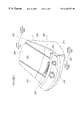
- FIG. 5 illustrates a cross section of a portion of a housing supporting a stylus holder.
- FIG. 6 illustrates a cross section of a stylus holder supporting a stylus.
- a computer cradle 100 is shown in FIG. 1 .
- the computer cradle 100 is an embodiment of the system when the computer cradle 100 is coupled to a computer 105 and a portable computer 110 .
- the computer cradle 100 is substantially enclosed in a housing 115 . Both a docking port 120 and a computer port 125 are coupled to a cradle circuit 130 .
- the portable computer 110 is coupled to the docking port 120 .
- the computer 105 is coupled to the computer port 125 .
- the portable computer 110 and the computer 105 exchange through the cradle circuit 130 , information related to functions such as an address book, a daily organizer, and a to do list.
- inventions include computer cradles of different sizes to accept desktop computers and laptop computers. Further embodiments include computer cradles that couple via the computer port to laptop computers, portable computers, and desktop computers.
- the cradle circuit 130 includes a light source circuit 135 , which comprises a light source 140 .
- the light source circuit 135 activates the light source 140 when the portable computer 110 is coupled to the docking port 120 .
- the light source 140 is active, light 145 is transmitted to a stylus holder 150 .
- the stylus holder 150 is made at least partially of light transmissive material, thereby transmitting at least some of the light 145 through the stylus holder 150 and illuminating the stylus holder 150 from a point of view external to the computer cradle 100 . Combining the stylus holder 150 with a light indicator can simplify some aspects of the manufacturing process of the computer cradle 100 , allows the stylus holder 150 to communicate information, and makes the stylus holder 150 easy to find and use.
- One embodiment of the stylus holder 150 is a light pipe having a cavity to support a stylus.
- Various embodiments of the stylus holder 150 use light transmissive materials such as glass, plastic, Lexanrm, translucent material, transparent material, and other materials that transmit light.
- Other embodiments use multiple materials of varying opacity and color.
- Further embodiments use materials with various patterns such as spots, stripes, and cross-hatching. Such patterns obscure any stray marks inadvertently made on the stylus holder 150 by, for example, a pen placed in the stylus holder 150 .
- Yet further embodiments use a stylus holder 150 integral to the housing 115 .
- the stylus holder 150 in these embodiments is light transmissive by virtue of a housing 115 that is thinner in the region of the stylus holder 150 .
- the stylus holder 150 is coupled to the docking port 120 .
- the light source circuit 135 is included in an electrical connection between the light source 140 and the docking port 120 . Coupling the portable computer 110 to the docking port 120 completes an electrical circuit, activating the light source 140 through the electrical connection. In other embodiments, the light source 140 indicates one of several charge statuses to indicate remaining power of the portable computer 110 . In various embodiments, the light source circuit 135 includes circuits that cause the light source 140 to blink at varying rates and cause the brightness of the light source 140 to vary among several brightness levels. In other embodiments, part of the light source 140 blinks at one rate and another part of the light source blinks at another rate. In further embodiments, part of the light source emits light at one brightness level and another part of the light source emits light at another brightness level.
- These various embodiments of the light source 140 and the light source circuit 135 communicate information to the user, such as ongoing data transfer, a stage of data transfer, data transfer rate, charge state of the portable computer 110 , connection state with the portable computer 110 , connection state with the computer 105 , and/or reminders of an appointment stored in the portable computer 110 or the computer 105 .
- the light source 140 in one embodiment includes one or more light emitting diodes (LEDs) positioned such that light emitted from the LEDs enters the stylus holder 150 .
- LEDs light emitting diodes
- the light source 140 emits multiple colors.
- one or more incandescent bulbs emit the light.
- the particular physics underlying the generation of light, for example incandescence and spontaneous photon emission, is not important. What is important is that the light source 140 generates light.
- FIG. 2 illustrates the computer cradle 100 from a front right perspective view.
- the housing 115 has a front face 200 , a right side 205 , a left side 210 , a base 215 , and a rear face 220 .
- the housing 115 comprises an upper housing 225 and a lower housing 230 .
- Viewing the computer cradle 100 from the right side 205 the line 235 illustrates a line along which the housing 115 is divided into the upper housing 225 and the lower housing 230 .
- the housing 115 includes the stylus holder 150 and the docking port 120 .
- FIG. 3 illustrates from a front left perspective view a computer cradle 100 that is partially assembled.
- the lower housing 230 of the housing 115 is shown, but not the upper housing 225 .
- a circuit board 300 rests in the lower housing 230 .
- the docking port 120 and the cradle circuit 130 (not shown) are positioned on the circuit board 300 .
- a stylus 305 is supported by the stylus holder 150 .
- a ballast (not shown) rests in the lower housing 230 beneath the circuit board 300 . The ballast adds stability to the computer cradle 100 .
- FIG. 4 illustrates the circuit board 300 , which supports the stylus holder 150 .
- the circuit board 300 has a notch 400 that prevents the circuit board 300 from blocking a stylus inserted into stylus holder 150 , allowing the stylus to rest more deeply in the stylus holder 150 .
- the notch 400 also removes from view the circuit board 300 which would otherwise be visible through the stylus holder 150 when the stylus holder 150 is not supporting the stylus.
- the stylus holder 150 is enclosed in a holder housing 405 .
- the holder housing 405 is coupled to the housing 115 via heat stakes.
- the heat stakes on the housing 115 are perpendicular to the front face 200 of the housing 115 to facilitate automated assembly of the holder housing 405 with the housing 115 .
- the heat stake receivers, or holes, on the holder housing 405 are not perpendicular to the front face 200 of the housing 115 .
- the heat stake receivers are sized large enough such that the heat stake receivers, which have a longitudinal axis not parallel to a longitudinal axis of the heat stakes, can accept the heat stakes.
- Other embodiments may use ultrasonic welding, cold stakes, clips, and/or fasteners to couple the holder housing 405 to the housing 115 .
- FIG. 5 illustrates a cross section of the stylus holder 150 supported in a cavity in the holder housing 405 .
- the cross section of the cavity has an hourglass shape, with an upper portion 500 and a lower portion 505 , separated by a line 510 .
- the upper portion 500 is shown as an upper portion first side 500 a and an upper portion second side 500 b .
- the lower portion 505 is shown as a lower portion first side 505 a and a lower portion second side 505 b .
- An upper portion cross sectional width 515 reaches from the upper portion first side 500 a to the upper portion second side 500 b .
- the upper portion cross sectional width 515 narrows with increased proximity to the lower portion 505 .
- a lower portion cross sectional width 520 reaches from the lower portion first side 505 a to the lower portion second side 505 b .
- the lower portion cross sectional width 520 narrows with increased proximity to the upper portion 500 .
- the cavity of the holder housing 405 has a longitudinal axis 525 .
- the stylus holder 150 has a stylus cavity 530 adapted to support a substantially cylindrical stylus.
- the stylus holder 150 has a longitudinal axis 535 .
- Line 540 represents a plane of the base 215 .
- Line 545 is parallel to longitudinal axis 525 .
- the approximately 45 degree angle between the line 545 and the line 540 represents the angle at which a stylus would be supported with respect to the plane of the base 215 , in an embodiment lacking the hourglass-shaped cross section of the housing cavity.
- the approximately 60 degree angle between the line 535 and the line 540 represents the angle at which a stylus would be supported with respect to the plane of the base 215 , in an embodiment having the hourglass-shaped cross section of the housing cavity.
- the hourglass-shaped housing cavity allows the stylus holder 150 to support a stylus at an angle ergonomically advantageous for a user, allowing the user to more easily reach the stylus in the stylus holder 150 and replace the stylus in the stylus holder 150 .
- the approximately 60 degree angle corresponds to an approximately 120 degree angle from the base 215 .
- FIG. 6 illustrates a cross section of the stylus holder 150 included in the holder housing 405 .
- the cross section of the stylus holder 150 has an upper part 150 a and a lower part 150 b .
- Neither the heat stake receivers of the holder housing 405 nor the main body of the holder housing 405 , which includes the stylus holder 150 is perpendicular to the front face 200 of the housing 115 .
- one portion of the stylus holder 150 forms an acute angle 605 with respect to the front face 200 of the housing 115
- another portion of the stylus holder 150 forms an obtuse angle 610 with respect to the front face 200 of the housing 115 .
- the stylus holder 150 has a first end 152 and a second end 154 .
- the first end 152 of the stylus holder 150 is shown in two parts 152 a and 152 b
- the second end 154 of the stylus holder 150 is shown in two parts 154 a and 154 b .
- a cross sectional width 615 reaches from the upper part 150 a to the lower part 150 b .
- the cross sectional width 615 is longer at the first end 152 than at the second end 154 .
- the stylus holder 150 thereby defines a funnel-shaped cavity which is adapted to support a stylus 305 and particularly a stylus 305 with a tapered tip 620 .
- the funnel-shaped cavity has a first opening 625 at the first end 152 of the stylus holder 150 and a second opening 630 at the second end 154 of the stylus holder 150 .
- the funnel-shaped cavity is not centered with respect to a longitudinal axis 635 of the stylus holder 150 .
- the first opening 625 is centered, but the second opening 630 is not centered, with respect to the longitudinal axis 635 .
- Line 640 represents a plane of the base 215 .
- Line 650 is perpendicular to the front face 200 of the housing 115 .
- the approximately 45 degree angle between the line 650 and the line 640 represents the angle at which a stylus 305 would be supported with respect to the plane of the base 215 , in an embodiment lacking both the funnel-shaped cavity of the stylus holder 150 and the non-perpendicular orientation of the stylus holder 150 with respect to the front face 200 of the housing 115 .
- the stylus 305 has a longitudinal axis 655 .
- the approximately 60 degree angle between the line 655 and the line 640 represents the angle at which a stylus 305 would be supported with respect to the plane of the base 215 .
- the stylus holder 150 thereby supports the stylus 305 at an angle ergonomically advantageous for a user, allowing the user to more easily reach the stylus 305 in the stylus holder 150 and replace the stylus 305 in the stylus holder 150 .
- the approximately 60 degree angle also corresponds to an approximately 120 degree angle from the base 215 .
- the stylus 305 would be supported at approximately angles of 30 degrees, 90 degrees, 120 degrees, and 150 degrees with respect to the plane of the base 215 , or any angle between 20-160 degrees with respect to the plane of the base 215 .
- the longitudinal axis of the holder housing 405 forms angles approximately of 30 degrees and 60 degrees, or any angle between 20-80 degrees with respect to the plane of the base 215 . All the above angles are for illustration only and other embodiments include different angle combinations not limited to the angles above.
- Other embodiments include different cross sections of the housing cavity, stylus holders seated at different positions in the housing cavity, adjustable stylus holders adapted to support a stylus at a range of angles with respect to the base 215 , and stylus holders with stylus cavities of various cross sections to accommodate styluses of various shapes and hues.
Abstract
Description
Claims (39)
Priority Applications (1)
| Application Number | Priority Date | Filing Date | Title |
|---|---|---|---|
| US09/283,668 US6246577B1 (en) | 1999-04-01 | 1999-04-01 | Cradle with combined status indicator light and stylus holder |
Applications Claiming Priority (1)
| Application Number | Priority Date | Filing Date | Title |
|---|---|---|---|
| US09/283,668 US6246577B1 (en) | 1999-04-01 | 1999-04-01 | Cradle with combined status indicator light and stylus holder |
Publications (1)
| Publication Number | Publication Date |
|---|---|
| US6246577B1 true US6246577B1 (en) | 2001-06-12 |
Family
ID=23087050
Family Applications (1)
| Application Number | Title | Priority Date | Filing Date |
|---|---|---|---|
| US09/283,668 Expired - Lifetime US6246577B1 (en) | 1999-04-01 | 1999-04-01 | Cradle with combined status indicator light and stylus holder |
Country Status (1)
| Country | Link |
|---|---|
| US (1) | US6246577B1 (en) |
Cited By (17)
| Publication number | Priority date | Publication date | Assignee | Title |
|---|---|---|---|---|
| US6621697B2 (en) | 2001-05-24 | 2003-09-16 | Palm, Inc. | Stylus visual indicator system |
| US20030225939A1 (en) * | 2002-05-28 | 2003-12-04 | Ying Alan J. | Docking stations for transferring data between handheld electronic devices and other devices via infrared communications |
| US20030229793A1 (en) * | 2002-01-11 | 2003-12-11 | Mccall Melvin D. | Transaction terminal comprising imaging module |
| US6672558B2 (en) * | 2000-08-18 | 2004-01-06 | Darfon Electronics Corp. | Holding apparatus for information input devices |
| US20040041797A1 (en) * | 2002-08-28 | 2004-03-04 | Burrus Philip H. | Fuel gauge stylus |
| US20050039052A1 (en) * | 2002-01-11 | 2005-02-17 | O'donnell James | Ease of use transaction terminal |
| US20050085123A1 (en) * | 1999-08-23 | 2005-04-21 | Jerry Moscovitch | Universal quick connector apparatus for an LCD monitor |
| US20050146845A1 (en) * | 1998-11-20 | 2005-07-07 | Jerry Moscovitch | Computer display screen system and adjustable screen mount, and swinging screens therefor |
| US6924791B1 (en) * | 2000-03-09 | 2005-08-02 | Palmone, Inc. | Method and apparatus for automatic power-up and power-down of a computer system based on the positions of an associated stylus and/or hinge |
| US20060133015A1 (en) * | 2004-12-17 | 2006-06-22 | First International Computer Inc. | Stylus attachment structure for it products |
| US20060181637A1 (en) * | 2005-02-16 | 2006-08-17 | Innovative Office Products, Inc. | Quick release assembly for an electronic device |
| US20060244737A1 (en) * | 2005-05-02 | 2006-11-02 | Microsoft Corporation | Flexible pen holder for a computer |
| US20080102675A1 (en) * | 2006-10-31 | 2008-05-01 | Ben Michaeli | Locking Cradle for a mobile device |
| US7748620B2 (en) | 2002-01-11 | 2010-07-06 | Hand Held Products, Inc. | Transaction terminal including imaging module |
| US20100315210A1 (en) * | 2009-06-16 | 2010-12-16 | Travis Ward C | Electronic device dock with replicating status indicator |
| US9904319B2 (en) * | 2016-05-17 | 2018-02-27 | Asustek Computer Inc. | Tablet |
| US10391808B2 (en) * | 2016-12-01 | 2019-08-27 | Wacom Co., Ltd. | Pen holder |
Citations (3)
| Publication number | Priority date | Publication date | Assignee | Title |
|---|---|---|---|---|
| US5375076A (en) * | 1993-09-10 | 1994-12-20 | Compaq Computer Corporation | Combined notepad and notebook computer |
| US5657459A (en) * | 1992-09-11 | 1997-08-12 | Canon Kabushiki Kaisha | Data input pen-based information processing apparatus |
| US5889512A (en) * | 1994-03-02 | 1999-03-30 | Apple Computer, Inc. | Extendible stylus |
-
1999
- 1999-04-01 US US09/283,668 patent/US6246577B1/en not_active Expired - Lifetime
Patent Citations (3)
| Publication number | Priority date | Publication date | Assignee | Title |
|---|---|---|---|---|
| US5657459A (en) * | 1992-09-11 | 1997-08-12 | Canon Kabushiki Kaisha | Data input pen-based information processing apparatus |
| US5375076A (en) * | 1993-09-10 | 1994-12-20 | Compaq Computer Corporation | Combined notepad and notebook computer |
| US5889512A (en) * | 1994-03-02 | 1999-03-30 | Apple Computer, Inc. | Extendible stylus |
Cited By (32)
| Publication number | Priority date | Publication date | Assignee | Title |
|---|---|---|---|---|
| US20050146845A1 (en) * | 1998-11-20 | 2005-07-07 | Jerry Moscovitch | Computer display screen system and adjustable screen mount, and swinging screens therefor |
| US7390211B2 (en) | 1999-08-23 | 2008-06-24 | Jerry Moscovitch | Universal quick connector apparatus for an LCD monitor |
| US20080149796A1 (en) * | 1999-08-23 | 2008-06-26 | Jerry Moscovitch | Universal Quick Connector Apparatus For An LCD Monitor |
| US7594823B2 (en) * | 1999-08-23 | 2009-09-29 | Jerry Moscovitch | Universal quick connector apparatus for an LCD monitor |
| US20050085123A1 (en) * | 1999-08-23 | 2005-04-21 | Jerry Moscovitch | Universal quick connector apparatus for an LCD monitor |
| US6924791B1 (en) * | 2000-03-09 | 2005-08-02 | Palmone, Inc. | Method and apparatus for automatic power-up and power-down of a computer system based on the positions of an associated stylus and/or hinge |
| US7626582B1 (en) | 2000-03-09 | 2009-12-01 | Palm, Inc. | Method and apparatus for automatic power-up and power-down of an electronic device |
| US6672558B2 (en) * | 2000-08-18 | 2004-01-06 | Darfon Electronics Corp. | Holding apparatus for information input devices |
| USRE41637E1 (en) * | 2001-05-24 | 2010-09-07 | Palm, Inc. | Stylus visual indicator system |
| US6621697B2 (en) | 2001-05-24 | 2003-09-16 | Palm, Inc. | Stylus visual indicator system |
| US7748620B2 (en) | 2002-01-11 | 2010-07-06 | Hand Held Products, Inc. | Transaction terminal including imaging module |
| US8544737B2 (en) | 2002-01-11 | 2013-10-01 | Hand Held Products, Inc. | Terminal including imaging assembly |
| US8967468B2 (en) | 2002-01-11 | 2015-03-03 | Hand Held Products, Inc. | Terminal including imaging assembly |
| US9734493B2 (en) | 2002-01-11 | 2017-08-15 | Hand Held Products, Inc. | Terminal including imaging assembly |
| US8561895B2 (en) | 2002-01-11 | 2013-10-22 | Hand Held Products, Inc. | Terminal including imaging assembly |
| US20030229793A1 (en) * | 2002-01-11 | 2003-12-11 | Mccall Melvin D. | Transaction terminal comprising imaging module |
| US20050039052A1 (en) * | 2002-01-11 | 2005-02-17 | O'donnell James | Ease of use transaction terminal |
| US20030225939A1 (en) * | 2002-05-28 | 2003-12-04 | Ying Alan J. | Docking stations for transferring data between handheld electronic devices and other devices via infrared communications |
| US6895445B2 (en) * | 2002-05-28 | 2005-05-17 | Mercurymd, Inc. | Docking stations for transferring data between handheld electronic devices and other devices via infrared communications |
| US7184033B2 (en) * | 2002-08-28 | 2007-02-27 | Motorola Inc. | Fuel gauge stylus |
| US20040041797A1 (en) * | 2002-08-28 | 2004-03-04 | Burrus Philip H. | Fuel gauge stylus |
| US7385596B2 (en) * | 2004-12-17 | 2008-06-10 | First International Computer Inc. | Stylus attachment structure for IT products |
| US20060133015A1 (en) * | 2004-12-17 | 2006-06-22 | First International Computer Inc. | Stylus attachment structure for it products |
| US7673838B2 (en) | 2005-02-16 | 2010-03-09 | Innovative Office Products, Inc. | Quick release assembly for an electronic device |
| US20060181637A1 (en) * | 2005-02-16 | 2006-08-17 | Innovative Office Products, Inc. | Quick release assembly for an electronic device |
| US7623121B2 (en) * | 2005-05-02 | 2009-11-24 | Microsoft Corporation | Flexible pen holder for a computer |
| US20060244737A1 (en) * | 2005-05-02 | 2006-11-02 | Microsoft Corporation | Flexible pen holder for a computer |
| US20080102675A1 (en) * | 2006-10-31 | 2008-05-01 | Ben Michaeli | Locking Cradle for a mobile device |
| US8174380B2 (en) | 2009-06-16 | 2012-05-08 | Apple Inc. | Electronic device dock with replicating status indicator |
| US20100315210A1 (en) * | 2009-06-16 | 2010-12-16 | Travis Ward C | Electronic device dock with replicating status indicator |
| US9904319B2 (en) * | 2016-05-17 | 2018-02-27 | Asustek Computer Inc. | Tablet |
| US10391808B2 (en) * | 2016-12-01 | 2019-08-27 | Wacom Co., Ltd. | Pen holder |
Similar Documents
| Publication | Publication Date | Title |
|---|---|---|
| US6246577B1 (en) | Cradle with combined status indicator light and stylus holder | |
| US6361357B1 (en) | Remotely illuminated electronic connector for improving viewing of status indicators | |
| US10847985B2 (en) | Flashlight with longitudinal cooling fins | |
| US7004596B2 (en) | Illuminated document copyholder | |
| US7270579B2 (en) | Recharging unit | |
| KR100858298B1 (en) | Shelf for depositing a keyboard | |
| US20140292656A1 (en) | Fingertip Mouse and Base | |
| US20120026682A1 (en) | Attachable holder for items | |
| EP1186985A2 (en) | Information processing device | |
| US11063398B2 (en) | Hub | |
| US20030227770A1 (en) | Portable illuminating device for connecting with computer | |
| US6747633B2 (en) | Wireless mouse recharge system | |
| US20050207144A1 (en) | Light retainer | |
| CN101119616A (en) | Cabinet for display module | |
| JP2004013843A (en) | Information processor | |
| US8378977B2 (en) | Device for electronically capturing a handwritten user input | |
| US20030043111A1 (en) | Portable storage device for presentation | |
| JP2003016395A (en) | Ic card reader, ic card reader main body, card holder, and support member | |
| US6517069B1 (en) | Light apparatus for illuminating a compact computer video screen | |
| CN220421862U (en) | Luminous acrylic mobile phone support | |
| US6906917B2 (en) | Web pad module with coupling devices installed on a rear side of a web pad | |
| CN217824384U (en) | Mouse charging device | |
| CN209881023U (en) | Charging wire | |
| US20040061423A1 (en) | Lamps | |
| CN210075771U (en) | Case with touch screen |
Legal Events
| Date | Code | Title | Description |
|---|---|---|---|
| AS | Assignment |
Owner name: 3COM CORPORATION, CALIFORNIA Free format text: ASSIGNMENT OF ASSIGNORS INTEREST;ASSIGNORS:HAN, AMY A.;NEIST, TRACI A.;TAL, ELISHA A.;AND OTHERS;REEL/FRAME:010069/0706;SIGNING DATES FROM 19990609 TO 19990626 |
|
| AS | Assignment |
Owner name: PALM, INC., CALIFORNIA Free format text: ASSIGNMENT OF ASSIGNORS INTEREST;ASSIGNOR:3COM CORPORATION;REEL/FRAME:011333/0953 Effective date: 20000621 |
|
| STCF | Information on status: patent grant |
Free format text: PATENTED CASE |
|
| FPAY | Fee payment |
Year of fee payment: 4 |
|
| FEPP | Fee payment procedure |
Free format text: PAYOR NUMBER ASSIGNED (ORIGINAL EVENT CODE: ASPN); ENTITY STATUS OF PATENT OWNER: LARGE ENTITY Free format text: PAYER NUMBER DE-ASSIGNED (ORIGINAL EVENT CODE: RMPN); ENTITY STATUS OF PATENT OWNER: LARGE ENTITY |
|
| AS | Assignment |
Owner name: JPMORGAN CHASE BANK, N.A., NEW YORK Free format text: SECURITY AGREEMENT;ASSIGNOR:PALM, INC.;REEL/FRAME:020317/0256 Effective date: 20071024 |
|
| FPAY | Fee payment |
Year of fee payment: 8 |
|
| AS | Assignment |
Owner name: PALM, INC., CALIFORNIA Free format text: RELEASE BY SECURED PARTY;ASSIGNOR:JPMORGAN CHASE BANK, N.A., AS ADMINISTRATIVE AGENT;REEL/FRAME:024630/0474 Effective date: 20100701 |
|
| AS | Assignment |
Owner name: HEWLETT-PACKARD DEVELOPMENT COMPANY, L.P., TEXAS Free format text: ASSIGNMENT OF ASSIGNORS INTEREST;ASSIGNOR:PALM, INC.;REEL/FRAME:025204/0809 Effective date: 20101027 |
|
| FPAY | Fee payment |
Year of fee payment: 12 |
|
| AS | Assignment |
Owner name: PALM, INC., CALIFORNIA Free format text: ASSIGNMENT OF ASSIGNORS INTEREST;ASSIGNOR:HEWLETT-PACKARD DEVELOPMENT COMPANY, L.P.;REEL/FRAME:030341/0459 Effective date: 20130430 |
|
| FEPP | Fee payment procedure |
Free format text: PAYER NUMBER DE-ASSIGNED (ORIGINAL EVENT CODE: RMPN); ENTITY STATUS OF PATENT OWNER: LARGE ENTITY Free format text: PAYOR NUMBER ASSIGNED (ORIGINAL EVENT CODE: ASPN); ENTITY STATUS OF PATENT OWNER: LARGE ENTITY |
|
| AS | Assignment |
Owner name: HEWLETT-PACKARD DEVELOPMENT COMPANY, L.P., TEXAS Free format text: ASSIGNMENT OF ASSIGNORS INTEREST;ASSIGNOR:PALM, INC.;REEL/FRAME:031837/0239 Effective date: 20131218 Owner name: HEWLETT-PACKARD DEVELOPMENT COMPANY, L.P., TEXAS Free format text: ASSIGNMENT OF ASSIGNORS INTEREST;ASSIGNOR:PALM, INC.;REEL/FRAME:031837/0659 Effective date: 20131218 Owner name: PALM, INC., CALIFORNIA Free format text: ASSIGNMENT OF ASSIGNORS INTEREST;ASSIGNOR:HEWLETT-PACKARD DEVELOPMENT COMPANY, L.P.;REEL/FRAME:031837/0544 Effective date: 20131218 |
|
| AS | Assignment |
Owner name: QUALCOMM INCORPORATED, CALIFORNIA Free format text: ASSIGNMENT OF ASSIGNORS INTEREST;ASSIGNORS:HEWLETT-PACKARD COMPANY;HEWLETT-PACKARD DEVELOPMENT COMPANY, L.P.;PALM, INC.;REEL/FRAME:032132/0001 Effective date: 20140123 |