US6295278B1 - ATM device - Google Patents
ATM device Download PDFInfo
- Publication number
- US6295278B1 US6295278B1 US09/044,656 US4465698A US6295278B1 US 6295278 B1 US6295278 B1 US 6295278B1 US 4465698 A US4465698 A US 4465698A US 6295278 B1 US6295278 B1 US 6295278B1
- Authority
- US
- United States
- Prior art keywords
- cell
- memory
- extracted
- atm device
- performance monitor
- Prior art date
- Legal status (The legal status is an assumption and is not a legal conclusion. Google has not performed a legal analysis and makes no representation as to the accuracy of the status listed.)
- Expired - Fee Related
Links
Images


Classifications
-
- H—ELECTRICITY
- H04—ELECTRIC COMMUNICATION TECHNIQUE
- H04L—TRANSMISSION OF DIGITAL INFORMATION, e.g. TELEGRAPHIC COMMUNICATION
- H04L12/00—Data switching networks
- H04L12/54—Store-and-forward switching systems
- H04L12/56—Packet switching systems
- H04L12/5601—Transfer mode dependent, e.g. ATM
- H04L2012/5625—Operations, administration and maintenance [OAM]
-
- H—ELECTRICITY
- H04—ELECTRIC COMMUNICATION TECHNIQUE
- H04L—TRANSMISSION OF DIGITAL INFORMATION, e.g. TELEGRAPHIC COMMUNICATION
- H04L12/00—Data switching networks
- H04L12/54—Store-and-forward switching systems
- H04L12/56—Packet switching systems
- H04L12/5601—Transfer mode dependent, e.g. ATM
- H04L2012/5629—Admission control
- H04L2012/5631—Resource management and allocation
- H04L2012/5636—Monitoring or policing, e.g. compliance with allocated rate, corrective actions
Definitions
- the present invention generally relates to ATM (Asynchronous Transfer Mode) devices, and more particularly to an ATM device which serves as an ATM NE (Network Element) provided in a subscriber line which connects connecting an ATM switch and a subscriber home. More particularly, the present invention is concerned with an ATM device which performs a PM (Performance Monitor) process, which is an OAM (Operation And Maintenance) function in the ATM layer.
- PM Performance Monitor
- OAM Operaation And Maintenance
- a conventional ATM device employs a structure as shown in FIG. 1 in order to perform the performance monitor process which is the OAM function in the ATM layer.
- an activation cell that includes an activate cell (hereinafter also referred to Act cell), an activate confirmed cell (hereinafter also referred to as ActConf cell), and activate request denied cell (hereinafter also referred to ActDenied cell).
- Act cell requests to start to execute the performance monitor process for performance test.
- ActConf cell permits starting to execute the performance monitor process.
- ActDenied cell denies starting to execute the performance monitor process.
- a deactivation cell which includes a deactivate cell (hereinafter also referred to as Deact cell), a deactivate confirmed cell (hereinafter also referred to as DeactConf cell), and a deactivate request denied cell (hereinafter also referred to as DeactDenied cell).
- the deactivate cell terminates the performance monitor process that is in progress.
- the deactivate confirmed cell permits terminating the performance test which is in progress.
- the deactivate request denied cell rejects termination of the performance test which is in progress.
- the ATM device shown in FIG. 1 includes an ACT/DACT cell extractor 301 , a cell information notification register 302 , a CPU 303 , a cell output specification register 304 , an ACT/DACT cell inserter 305 .
- the ACT/DACT cell extractor 301 extracts the activation cell and deactivation cell on the ATM network.
- the cell information notification register 302 temporarily stores the information of the cells extracted by the cell extractor 301 in order to notify the CPU 303 of the information.
- the CPU 303 controls the start and termination of the performance monitor process on the basis of the information from the register 302 .
- the cell output specification register 304 stores the activation cell and the deactivation cell to be output under the control of the CPU 303 .
- the ACT/DACT cell inserter 305 inserts, into the ATM network, the activation cell and the deactivation cell specified in the cell output specification register 304 .
- the CPU 303 is notified, via the register 302 , of the cell information concerning the activation cell and the deactivation cell extracted by the ACT/DACT cell extractor 301 , namely, cell information concerning the activate cell, activate confirmed cell, activate request denied cell, deactivate cell, deactivate confirmed cell and deactivate request denied cell.
- the CPU 303 analyzes the received cell information, and controls the start and termination of the performance monitor process and a response to a request issued from a remote terminal.
- the CPU 303 determines whether the performance monitor process should be started in a channel specified by the information provided in the activate cell.
- the CPU 303 instructs the cell output specification register 304 to output the activate confirmed cell.
- the ACT/DACT cell inserter 305 sends the specified activate confirmed cell to the ATM network.
- the CPU 303 instructs the cell output specification register 304 to output the activate request denied cell.
- the ACT/DACT cell inserter 305 sends the specified activate request denied cell to the ATM network.
- the CPU 303 determines whether the performance monitor process which is now in progress should be terminated in a channel specified by the information in the deactivate cell.
- the CPU 303 instructs the cell output specification register 304 to output the deactivate confirmed cell.
- the ACT/DACT cell inserter 305 sends the specified deactivate confirmed cell to the ATM network.
- termination of the performance monitor process is rejected, the CPU 303 instructs the cell output specification register 304 to output the deactivate request denied cell.
- the ACT/DACT cell inserter 305 sends the specified deactivate request denied cell to the ATM network.
- the CPU 303 determines whether the ACT/DACT cell extractor 301 extracts the activate confirmed cell or activate request denied cell. When the activate request denied cell is extracted, the CPU 303 starts the performance monitor process from the own device. When the activate request denied cell is extracted, the CPU 303 cannot start the performance monitor process from the own device.
- the CPU 303 determines whether the ACT/DACT cell extractor 301 extracts the deactivate confirmed cell or the deactivate request denied cell. When the deactivate confirmed cell is extracted, the CPU 303 terminals the performance monitor process which is in progress. When the deactivate request denied cell is extracted, the CPU 303 cannot terminate the performance monitor process that is in progress.
- the cell information notification register 302 of the conventional ATM device includes a memory 311 from which an interrupt request is applied to the CPU 303 when the memory 311 receives the cell information concerning the activate cell, activate confirmed cell, activate request denied cell, deactivate cell, deactivate confirmed cell and deactivate request denied cell.
- the CPU is informed of all the activation cell and the deactivation cell in the performance monitor process of the ATM layer.
- the CPU analyzes all the activation cell and the deactivation cell, and determines, for each VP/VC channel, whether the performance monitor process should be started or terminated. Further, the CPU controls a response to each of all requests from other devices.
- a more specific object of the present invention is to provide an ATM device capable of processing activation and deactivation cells which are really required to be processed by a CPU or the like.
- an ATM device comprising: an extractor which extracts a cell related to a performance monitor process for an ATM layer; a processing unit executing the performance monitor process; a memory which stores information concerning the performance monitor process; and a decision making unit which compares the information stored in the memory with cell information of the cell extracted by the extractor and which makes a decision as to whether the cell extracted by the extractor should be supplied to the process unit.
- the ATM device may be configured so that:
- the memory has memory areas equal in number of channels that can be processed by the processing unit;
- the memory areas respectively store cells extracted by the extractor.
- the ATM device may be configured so that:
- the memory has memory areas equal in number of channels that can be processed by the processing unit;
- the memory areas respectively store cells extracted by the extractor
- a memory state detector which determines whether there is any idle memory area in the memory
- the decision making unit determines that the cell extracted by the extractor should not be supplied to the processing unit when the cell extracted by the extractor requests initiation of the performance monitor process and the memory state detector determines that there is no idle memory area in the memory.
- the ATM device may be configured so that it further comprise a cell sending unit which sends a denied cell back to a network to which the ATM device is connected when it is determined that the cell extracted by the extractor should not be sent to the processing unit.
- the ATM device may be configured so that:
- the memory stores information indicating channels which are now subjected to the performance monitor process.
- the extracted by the extractor is not supplied to the processing unit when the decision making unit determines that cell information of the extracted cell coincides with the information stored in the memory.
- the ATM device may be configured so that: the memory stores information indicating a channel which is now subjected to the performance monitor process in response to a request issued by the ATM device and information indicating that a request to terminate the performance monitor process which is initiated in response to a request issued by the ATM device is issued by another ATM device should be neglected; and the cell extracted by the extractor is not supplied to the processing unit when the decision making unit determines that cell information of the extracted cell coincides with the information stored in the memory.
- the ATM device may be configured so that:
- the memory stores information indicating a channel which is now subjected to the performance monitor process in response to a request issued by the ATM device and information indicating a channel which is now on request for the performance monitor process;
- the cell extracted by the extractor is not supplied to the processing unit when the decision making unit determines that cell information of the extracted cell coincides with the information stored in the memory.
- the ATM device may be configured so that:
- the memory stores information indicating a channel which is now on request for initiation of the performance monitor process issued by the ATM device;
- the cell extracted by the extractor is not supplied to the processing unit when the cell requests a confirmation of initiation of the performance monitor process or denies the request for initiation of the performance monitor process and the decision making unit determines that cell information of the extracted cell does not coincide with the information stored in the memory.
- the ATM device may be configured so that:
- the memory stores information indicating a channel which is now on request for termination of the performance monitor process issued by the ATM device;
- the cell extracted by the extractor is not supplied to the processing unit when the cell requests a confirmation of termination of the performance monitor process or denies the request for termination of the performance monitor process and the decision making unit determines that cell information of the extracted cell does not coincide with the information stored in the memory.
- the ATM device may be configured so that:
- the memory stores information indicating a block size that can be processed by the processing unit
- the cell extracted by the extractor is not supplied to the processing unit when the decision making unit determines that the cell has a block size which is inconsistent with the block size stored in the memory.
- the ATM device may be configured that it may further comprise another memory which temporarily stores the cell extracted by the extractor and which is determined that the cell should be supplied to the processing unit, the processing unit periodically accessing said another memory and determines whether there is any cell to be processed.
- the ATM device may be configured so that a part of an address of said another memory is common to an address of said memory which stores the information concerning the performance monitor process.
- FIG. 1 is a block diagram of a conventional ATM device
- FIG. 2 is a block diagram of a structure which notifies a CPU of cell information of an extracted cell
- FIG. 3 is a block diagram of the principle of an ATM device according to the present invention.
- FIG. 4 is a block diagram of an ATM device according to a first embodiment of the present invention.
- FIG. 5 is a block diagram of an ATM device according to a second embodiment of the present invention.
- FIG. 6 is a block diagram of an ATM device according to a third embodiment of the present invention.
- FIG. 7 is a block diagram of an ATM device according to a fourth embodiment of the present invention.
- FIG. 8 is a block diagram of an ATM device according to a fifth embodiment of the present invention.
- FIG. 9 is a block diagram of an ATM device according to a sixth embodiment of the present invention.
- FIG. 10 is a block diagram of a structure which notifies a CPU of cell information of an extracted cell
- FIG. 11 is a block diagram of a hardware structure applicable to the embodiments of the present invention.
- FIG. 12 is a block diagram of an ATM device according to a seventh embodiment of the present invention.
- FIG. 13 is a diagram showing a format of an activation cell and a deactivation cell
- FIG. 14 is a diagram showing a header of the cell
- FIG. 15 is a diagram showing a message ID
- FIG. 16 is a diagram showing the detail of a direction of action.
- FIG. 17 is a diagram showing a block size of cell.
- FIG. 3 is a block diagram of the principle of the present invention.
- An ATM device shown in FIG. 3 includes an ACT/DACT cell extractor 1 , a performance monitor internal state management unit 2 , an address counter 3 , an ACT/DACT cell information notification register 4 , and a CPU 5 .
- the structure shown in FIG. 3 controls the start and termination of the performance monitor process which is the OAM function in the ATM layer, and a response to a request issued from another device.
- the ACT/DACT cell extractor 1 extracts the activation cell and the deactivation cell.
- the performance monitor internal state management unit 2 includes a performance monitor internal state information memory 6 , a comparator 7 , and a latch circuit 8 .
- the performance monitor internal state management unit 2 identifies only valid cells from among the activation cells and deactivation cells extracted by the extractor 1 on the basis of given information stored in the performance monitor internal state information memory 6 . In other words, invalid cells which are not identified have defective factors such as erroneous inserting, loss of cell and erroneous ordering. Hence, only valid cells are applied to the CPU 5 via the register 4 .
- the comparator 7 compares the extracted activation or deactivation cell with the information stored in the memory 6 , and determines whether the extracted cell is a valid cell to be supplied to the CPU 5 . When it is determined that the extracted cell is a valid cell, the latch circuit 8 latches the address of the memory 6 obtained at that time. The contents of the memory 6 can periodically be rewritten under control of the CPU 5 or a microcomputer (not shown in FIG. 3 ).
- the address counter 3 generates an address applied to the memory 6 when the activation or deactivation cell is extracted by the extractor 1 .
- the ACT/DACT cell information notification register 4 temporarily stores, at the address latched in the latch circuit 8 , the activation or deactivation cell which is determined as being a valid cell. The latched cell is then read from the register 4 and is supplied to the CPU 5 .
- the CPU 5 controls the start and termination of the performance monitor process and a response to a request from another device on the basis of the valid activation or deactivation cell supplied via the register 4 .
- the activation and deactivation cells have a format as shown in FIG. 13 .
- Each of the activation and deactivation cells consists of 54 bytes, and includes a header (1) and a payload (2).
- the payload (2) includes specific information field (3).
- the header (1) includes GFC (Generic Flow Control), VPI (Virtual Path Identifier), VCI (Virtual Channel Identifier), PTI (Payload Type Identifier), CLP (Cell Loss Priority), HEC (Header Error Control), and an OAM type and Fnc type.
- GFC Generic Flow Control
- VPI Virtual Path Identifier
- VCI Virtual Channel Identifier
- PTI Payment Type Identifier
- CLP Cell Loss Priority
- HEC Header Error Control
- OAM type and Fnc Type are respectively 1000 and 0000
- the extracted cell is the activation cell or the deactivation cell.
- the payload (2) includes, as information indicative of the activation and deactivation cells, a message ID, a direction of action (D-o-A), a correction tag, and information concerning the block size.
- the above information is defined every performance monitor subject section (VP segment, VP End to End, VC Segment, VC End to End).
- the message ID indicates to which one of the activate cell, activate confirmed cell, activate denied cell, deactivate cell, deactivate confirmed cell and deactivate denied cell the received cell corresponds (see FIG. 15 ).
- the direction-of-action information indicates the direction of the performance monitor process (see FIG. 16 ).
- the correction tag information indicates the number of times that the performance monitor process is retried.
- the block size indicates the number of user cells to be sent between performance monitor cells when the performance monitor process is executed (see FIG. 17 ).
- FIG. 15 shows the detail of the message ID.
- the message ID is set to 000001 when the received cell is the activate cell.
- the message ID is set to 000010 when the received cell is the activate confirmed cell.
- the message ID is set to 000011 when the received cell is the activate request denied cell.
- the message ID is set to 000101 when the received cell is the deactivate cell.
- the message ID is set to 000110 when the received cell is the deactivate confirmed cell.
- the message ID is set to 000111 when the received cell is the deactivate request denied cell.
- the direction-of-action information is set to 01 when the performance monitor process is oriented from another ATM device to the own ATM device (indicated as B to A in FIG. 16 ).
- the direction-of-action information is set to 10 when the performance monitor process is oriented from the own ATM device to another ATM device.
- the direction-of action information is set to 11 when the performance monitor process can be executed in two directions.
- the block size is set to 0001 when the number of user cells sent between the performance monitor cells when the performance monitor process is executed is equal to 1024.
- the block size is set to 0010 when the number of user cells sent between the performance monitor cells when the performance monitor process is executed is equal to 512.
- the block size is set to 0100 when the number of user cells sent between the performance monitor cells when the performance monitor process is executed is equal to 256.
- the block size is set to 1000 when the number of user cells sent between the performance monitor cells when the performance monitor process is executed is equal to 128.
- the ACT/DACT cell extractor 1 When the activation cell or the deactivation cell is extracted, the ACT/DACT cell extractor 1 generates a trigger signal Trig (FIG. 3) to the address counter 3 .
- the address counter 3 In response to the trigger signal, the address counter 3 generates the address of the performance monitor internal state information memory 6 . Then, the given information to be compared with the extracted activation or deactivation cell is read from the performance monitor internal state information memory 6 .
- the given information includes, for example, the VPI and VCI of the channel subjected to the performance monitor process, the performance monitor subject section, and code information indicative of the state of the performance monitor process.
- the code information indicates the following: non-entry cell; the activate cell is being requested; the performance monitor process is being processed; the deactivate cell is being requested; the activate cell time out; and the deactivate cell time out.
- the ATM device shown in FIG. 3 operates so that the CPU 5 analyzes only the valid activation and deactivation cells. Then, the CPU 5 starts and terminates the performance monitor process for each VP/VC channel, and control a response to a request from another ATM device. Hence, the CPU 5 is not required to process a larger number of VP/VC channels than the number of channels exceeding the allowed number of channels which can definitely be processed by the CPU 5 . The CPU 5 does not process the invalid cells having defective factors. Thus, the CPU 5 processes a reduced amount of data and has a reduced load. Hence, the CPU 5 operates efficiently.
- FIG. 4 is a block diagram of an ATM device according to a first embodiment of the present invention.
- the ATM device shown in FIG. 4 includes an activate cell extractor 11 , a performance monitor internal state management unit 12 , an address counter 13 , an ACT/DACT cell information notification register 14 , a CPU 15 and an activate request denied cell sending unit 16 .
- the activate cell extractor 11 extracts the activate cell on the ATM network.
- the performance monitor internal state management unit 12 includes a performance monitor internal state information memory 17 , a memory state detector 18 , a comparator 19 , an OR gate 20 and a latch circuit 21 .
- the comparator 19 compares the cell extracted by the extractor 11 with given information stored in the memory 17 in order to determine whether the extracted cell is valid.
- the memory state detector 18 monitors the state of the memory 17 and determines whether an idle area is available in the memory 17 .
- the OR gate 20 notifies the activate request denied cell sending unit 16 that the memory 17 is full of data or the extracted cell is invalid.
- the latch circuit 21 latches the address of the memory 17 applied thereto at that time.
- the address counter 13 receives the trigger signal Trig and then generates the address of the memory 17 when the activate cell extractor 11 extracts the activate cell.
- the ACT/DACT cell information notification register 14 temporarily stores the activate cell which is determined as being valid with the address supplied from the address counter 13 via the latch circuit 21 .
- the CPU 15 controls the performance monitor process in response to the activate cell read from the register 14 .
- the memory 17 has memory areas for storing the internal state information of the performance monitor equal in number to the channels for the performance monitor that can be processed by the CPU 5 . If there is no idle area in the memory 17 , the cell information of the extracted activate cell is not supplied to the CPU 5 . Hence, it is possible to prevent the CPU 5 from executing the performance monitor process over a larger number of channels than the tolerable number of channels that can definitely be processed by the CPU 5 . In this case, the ATM device is required to notify the ATM network that the activate cell is rejected. Hence, the memory state detector 18 sends the corresponding signal to the activate request denied cell sending unit 16 via the OR gate 20 in order to send the activate request denied cell to the network.
- the output signal of the comparator 19 is sent to the activate request denied cell sending unit 16 via the OR gate 20 .
- the activate request denied cell sending unit 16 sends the activate request denied cell to the ATM network in order to reject initiation of the performance monitor process when there is no idle area in the memory 17 or when the performance monitor process for the requested channel is already initiated.
- the activate request denied cell sending unit 16 includes an activate request denied cell generator 22 , a buffer 23 and an activate request denied cell inserter 24 .
- the activate request denied cell generator 22 generates the activate request denied cell using the extracted activate cell from the extractor 11 .
- the activate request denied cell thus generated is temporarily stored in the buffer 23 , and is inserted, via the activate request denied cell inserter 24 , into data transferred over the line connected to the ATM network. More particularly, the activate request denied cell is inserted in an idle section equal to one cell in the cell stream transferred over the line.
- the ATM device shown in FIG. 4 is advantageous to the prior art shown in FIG. 1 as follows.
- the CPU 303 shown in FIG. 1 is informed of all the activate cells and analyzes the activate cells.
- the CPU 303 is required to process a larger number of VP/VC channels than the tolerable number of channels for the performance monitor process that can be processed by the CPU 303 .
- the CPU 303 has a very heavy load.
- the CPU 303 is informed of invalid cells which have defective factors.
- the CPU 303 is required to receive and process an activate cell which requests the performance monitor process for a channel for which the performance monitor process is already initiated.
- the structure shown in FIG. 4 employs the memory 17 which has storage areas equal in number to channels which are subjected to the performance monitor process.
- the CPU 15 does not process a larger number of VP/VC channels than the number of channels provided in the memory 17 .
- the extracted activate cell related to the channel which is already subjected to the performance monitor process is rejected.
- the CPU 15 has a reduced load and thus operates efficiently.
- FIG. 5 is a block diagram of an ATM device according to a second embodiment of the present invention.
- the ATM device includes a deactivate cell extractor 31 , a performance monitor internal state management unit 32 , an address counter 33 , an ACT/DACT cell information notification register 34 , a CPU 35 and a deactivate request denied cell sending unit 36 .
- the performance monitor internal state management unit 32 includes a performance monitor internal state information memory 37 , a comparator 38 , an inverter 39 and a latch circuit 40 .
- the deactivate request denied cell sending unit 36 includes a deactivate request denied cell generator 41 , a buffer 42 and a deactivate request denied cell inserter 43 .
- the deactivate cell extractor 31 extracts the deactivate cell from the signal received via the line, and supplies a trigger signal to the address counter 33 , and supplies the management unit 32 with the cell information of the extracted deactivate cell.
- the address counter 33 generates the address of the memory 37 in response to the trigger signal from the extractor 31 .
- the internal state information of the performance monitor specified by the address supplied from the address counter 33 is read from the memory 37 and is supplied to the comparator 38 . Then, the comparator 38 compares the internal state information with the cell information of the extracted deactivate cell. If the internal state information read from the memory 37 shows that the activate cell related to the channel of interest is issued by the own ATM device and the deactivate cell issued by another ATM device should be neglected, it is recognized that the extracted deactivate cell should not be accepted. Then, the comparator 38 notifies the deactivate request denied cell generator 41 that the extracted cell should be neglected when the cell information of the extracted cell coincides with the above read internal state information. Then, the generator 41 generates the deactivate request denied cell from the deactivate cell from the extractor 31 . The above denied cell is send to the line via the buffer 42 and the inserter 43 .
- the output signal of the comparator 38 is applied to the latch circuit 40 via the inverter 39 when the cell information of the extracted deactivate cell coincides with the read initial state information. Then, the cell information from the extractor 31 is written into the register 34 with the address generated by the address counter 33 obtained via the latch circuit 60 .
- FIG. 6 is a block diagram of an ATM device according to a third embodiment of the present invention.
- the ATM device includes a deactivate cell extractor 51 , a performance monitor internal state management unit 52 , an address counter 53 , an ACT/DACT cell information notification register 54 , a CPU 55 and a deactivate confirmed cell sending unit 56 .
- the performance monitor internal state management unit 52 includes a performance monitor internal state information memory 57 , a comparator 58 , an inverter 59 and a latch circuit 60 .
- the deactivate confirmed cell sending unit 56 includes a deactivate confirmed cell generator 61 , a buffer 62 and a deactivate confirmed cell inserter 63 .
- the deactivate cell extractor 51 extracts the deactivate cell from the signal received via the line, and supplies a trigger signal to the address counter 53 , and supplies the management unit 52 with the cell information of the extracted deactivate cell.
- the address counter 53 generates the address of the memory 57 in response to the trigger signal from the extractor 51 .
- the internal state information of the performance monitor specified by the address supplied from the address counter 53 is read from the memory 57 and is supplied to the comparator 58 . Then, the comparator 58 compares the internal state information with the cell information of the extracted deactivate cell. In a case where the internal state information read from the memory 57 shows the VP/VC channel for which the performance monitor process is in progress or is now on request, if the cell information does not coincide with the above internal state information, it is recognized that the extracted deactivate cell is directed to a channel for which the performance monitor process is already deactivated or a channel which is not subjected to the performance monitor process.
- the corresponding output signal of the comparator 58 passes through the inverter 59 , and is applied to the deactivate confirmed cell generator 61 , which generates the deactivate confirmed cell from the extracted deactivate cell supplied from the extractor 51 .
- the deactivate confirmed cell is sent to the line via the buffer 62 and the deactivate confirmed cell inserter 63 .
- the cell information of the extracted deactivate cell coincides with the internal state information concerning the performance monitor, the cell information of the extracted deactivate cell is written into the register 54 with the address generated by the address counter 53 obtained via the latch circuit 60 .
- FIG. 7 is a block diagram of an ATM device according to a fourth embodiment of the present invention.
- the ATM device shown in FIG. 7 includes an activate confirmed cell/deactivate request denied cell extractor 71 , a performance monitor internal state management unit 72 , an address counter 73 , an ACT/DACT cell information notification register 74 and a CPU 75 .
- the performance monitor internal state management unit 72 includes a performance monitor internal state information memory 76 , a comparator 77 and a latch circuit 78 .
- the extractor 71 extracts the deactivate confirmed cell and the deactivate request denied cell from the signal transferred over the line. Then, the extractor 71 supplies a trigger signal to the memory 76 and the cell information of the extracted cell to the management unit 72 .
- the address counter 73 generates an address of the memory 76 .
- the comparator 77 compares the cell information of the extracted cell with the internal state information concerning the performance monitor read from the memory 76 .
- the internal state information stored in the memory 76 includes VP/VC channel information of the activate request issued by the own device. If the internal state information read from the memory 76 does not coincide with the cell information of the extracted cell, it is recognized that the extracted cell is a defective cell which may be erroneously inserted or may have a bit error.
- the comparator 77 disables the latch circuit 78 so that the cell information from the extractor 71 is prevented from being stored in the register 74 . If the internal state information read from the memory 76 coincides with the cell information of the extracted cell, the address generated by the address counter 73 is applied to the register via the latch circuit 78 , so that the cell information of the extracted cell is written into the register 74 .
- the defective cells are not supplied to the CPU 75 .
- the CPU 75 thus a reduced load and operates efficiently.
- FIG. 8 is a block diagram of an ATM device according to a fifth embodiment of the present invention.
- the ATM device shown in FIG. 8 includes a deactivate confirmed cell/deactivate request denied cell extractor 81 , a performance monitor internal state management unit 82 , an address counter 83 , an ACT/DACT cell information notification register 84 , and a CPU 85 .
- the performance monitor internal state management unit 82 includes a performance monitor internal state information memory 86 , a comparator 87 and a latch circuit 88 .
- the extractor 81 extracts the deactivate confirmed cell and the deactivate request denied cell from the signal transferred over the line. Then, the extractor 81 supplies a trigger signal to the memory 86 and the cell information of the extracted cell to the management unit 82 .
- the address counter 83 generates an address of the memory 86 .
- the comparator 87 compares the cell information of the extracted cell with the internal state information concerning the performance monitor read from the memory 86 .
- the internal state information stored in the memory 86 includes VP/VC channel information of the deactivate request issued by the own device. If the internal state information read from the memory 86 does not coincide with the cell information of the extracted cell, it is recognized that the extracted cell is a defective cell which may be erroneously inserted or may have a bit error.
- the comparator 87 disables the latch circuit 88 so that the cell information from the extractor 81 is prevented from being stored in the register 84 . If the internal state information read from the memory 86 coincides with the cell information of the extracted cell, the address generated by the address counter 83 is applied to the register via the latch circuit 88 , so that the cell information of the extracted cell is written into the register 84 .
- the defective cells are not supplied to the CPU 85 .
- the CPU 85 thus a reduced load and operates efficiently.
- FIG. 9 is a block diagram of an ATM device according to a sixth embodiment of the present invention.
- the ATM device shown in FIG. 9 includes an activate cell extractor 91 , an address counter 93 , an ACT/DACT cell information notification register 94 , a CPU 95 and an activate request defined cell sending unit 96 .
- the management unit 92 includes a performance monitor internal state memory 97 , a memory state detector 98 , an OR gate 99 , a block size detector 100 , a register 101 , a comparator 102 and a latch circuit 103 .
- the activate request denied cell sending unit 96 includes an activate request denied cell generator 104 , a buffer 105 and an activate cell request denied cell inserter 106 .
- the ATM device shown in FIG. 9 can be configured by adding the block size detector 100 and the register 101 to the configuration shown in FIG. 4 .
- the ATM device shown FIG. 9 corresponds to a modification of the ATM device shown in FIG. 4 .
- the activate cell extractor 91 extracts the activate cell from the signal transferred over the line. Then, the activate cell extractor 91 supplies a trigger signal to the address counter 93 , and supplies cell information of the extracted cell to the management unit 92 . In response to the trigger signal, the address counter 93 generates an address of the memory 97 . The internal state information concerning the performance monitor specified by the address is read from the memory 97 and is supplied to the memory state detector 98 , which operates in the same manner as the memory state detector 18 shown in FIG. 4 .
- the block size detector 100 detects the block size of the extracted cell by referring to the cell information thereof.
- the register 101 stores information concerning block sizes that can be processed by the CPU 95 .
- the comparator 102 compares the detected block size with the contents of the register 101 . If it is recognized that the block size of the extracted cell can be handled by the CPU 95 . In this case, the cell information of the extracted cell is allowed to the supplied to the CPU 95 via the register 94 . If it is recognized that the block size of the extracted cell cannot be handled by the CPU 95 , the comparator 102 supplies the corresponding signal to the OR gate 99 , which then outputs it to the activate request denied cell sending unit 96 . Hence, the activate cells having the block sizes which are inconsistent with the block sizes that can be handled by the CPU 95 are rejected.
- FIG. 10 is a block diagram of a hardware structure which supplies an extracted cell to a CPU, the above hardware structure being applied to any of the aforementioned embodiments of the present invention.
- An ACT/DACT cell extractor 111 extracts the activation cell and the deactivation cell from the signal transferred over the line. The extracted cell is then stored in a hardware formation in a memory 112 of the ACT/DACT cell information notification register used in each of the aforementioned embodiments of the present invention. Then, the extracted cell is read from the memory 112 and an external memory 113 .
- a CPU 114 to which the external memory 113 is connected via a bus periodically sends a polling signal to the memory 112 in order to periodically determine whether any new cell is stored in the memory 112 .
- the CPU 113 If a new cell stored in the memory 112 is confirmed, the CPU 113 reads the new cell from the external memory 113 and executes the necessary process which is any of the start and termination of the performance monitor process and generation of a response to a request issued by another device.
- the CPU 113 can access the memory 112 with a comparatively long period in order to determine whether there is any new cell in the memory 112 . Hence, it is possible to reduce the time necessary to check the presence/absence of new cells and thus reduce the load of the CPU.
- FIG. 11 is a block diagram of a hardware structure of a notification means that can be employed in any of the aforementioned embodiments of the present invention. More particularly, the notification means shown in FIG. 11 corresponds to the ACT/DACT cell information notification register shown in FIGS. 3 to 9 , and the memory 112 and the external memory 113 shown in FIG. 10 .
- a performance monitor internal state management unit 122 includes a RAM 127 and a comparator 128 .
- the RAM stores given information used to determine whether each extracted activation or deactivation cell should be supplied to the CPU.
- the comparator 128 performs the above determination process.
- An address counter 121 corresponds to the address counter used in each of the embodiments of the present invention.
- the address counter 121 generates an address of the RAM 127 when the valid cell is extracted.
- the structure shown in FIG. 11 includes an upper address generator 123 , a lower address generator 124 , a dual-port RAM 125 and a shifter 126 .
- the upper address generator 123 recites the address generated by the address counter 121 as an upper address of the dual-port RAM 125 when it is determined that the extracted cell should be supplied to the CPU.
- the lower address generator generates a lower address of the dual-port RAM 125 , the lower address being related to items of the cell information to be supplied to the CPU.
- part of the address of the dual-port RAM 125 is common to the address generated by the address counter 121 , so that the hardware can be implemented efficiently.
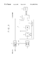
- FIG. 12 is a block diagram of an ATM device according to a seventh embodiment of the present invention.
- the ATM device shown in FIG. 12 includes all the functions of the aforementioned first through sixth embodiments of the present invention.
- An activation cell/deactivation cell extractor 201 corresponds to the cell extractors shown in FIGS. 4 through 9.
- a performance monitor internal state management unit 202 corresponds to those shown in FIGS. 4 through 9.
- An address counter 203 corresponds to those shown in FIGS. 4 through 9.
- a notification unit 204 corresponds to those shown in FIGS. 10 and 11.
- a CPU 205 corresponds to those shown in FIGS. 4 through 9.
- a cell sending unit 206 corresponds to those shown in FIGS. 4, 5 , 6 and 9 .
- the performance monitor internal state management unit 202 includes a performance monitor internal state memory 210 , a shifter 211 , a selector 212 , a dual-port RAM 213 , a comparator 214 , a memory state detector 215 , a block size register 216 , a comparator 217 , and a decision making unit 218 .
- the memory 210 corresponds to those shown in FIGS. 4 through 9.
- the comparator 214 corresponds to those shown in FIGS. 4 through 8.
- the memory state detector 215 corresponds to those shown in FIGS. 3 and 9.
- the register 21 6 corresponds to th at shown in FIG. 9 .
- the comparator 217 corresponds to that shown in FIG. 9 .
- the decision making unit 218 receives the output signals of the comparators 214 and 217 and the output signal of the memory state detector 215 and makes the aforementioned decision as to whether the received cell should be supplied to the CPU 206 .
- the notification unit 204 includes an upper address generator 207 corresponding to that shown in FIG. 11, a lower address generator 208 corresponding to that shown in FIG. 11, a dual-port RAM 206 corresponding to the memory 112 and the external memory 113 shown in FIG. 10 and the dual-port RAM 125 shown in FIG. 11, and a shifter 209 corresponding to that shown in FIG. 11 .
- the cell recognized being valid is stored in the dual-port RAM 206 in accordance with the upper and lower addresses respectively supplied from the generators 207 and 208 .
- the cell stored in the dual-port RAM 206 is then read therefrom in response to the polling signal from the CPU 205 .
- the cell sending unit 223 includes a cell generator corresponding to those shown in FIGS. 4 to 6 and 9 , a cell insertion arbitrator 220 corresponding the buffers shown in FIGS. 4 to 6 and 9 , and an activation/deactivation cell inserter 221 corresponding to the cell inserters shown in FIGS. 4-6 and 9 .
- the cell sending unit 223 can send the line the active request denied cell, deactivate request denied cell and the deactivate confirmed cell.
- the ATM device shown in FIG. 12 has all the functions provided by the aforementioned first to sixth embodiments of the present invention and all the effects thereof.
Abstract
Description
Claims (15)
Applications Claiming Priority (2)
| Application Number | Priority Date | Filing Date | Title |
|---|---|---|---|
| JP28574997A JP3438807B2 (en) | 1997-10-17 | 1997-10-17 | ATM equipment |
| JP9-285749 | 1997-10-17 |
Publications (1)
| Publication Number | Publication Date |
|---|---|
| US6295278B1 true US6295278B1 (en) | 2001-09-25 |
Family
ID=17695559
Family Applications (1)
| Application Number | Title | Priority Date | Filing Date |
|---|---|---|---|
| US09/044,656 Expired - Fee Related US6295278B1 (en) | 1997-10-17 | 1998-03-19 | ATM device |
Country Status (2)
| Country | Link |
|---|---|
| US (1) | US6295278B1 (en) |
| JP (1) | JP3438807B2 (en) |
Cited By (1)
| Publication number | Priority date | Publication date | Assignee | Title |
|---|---|---|---|---|
| US20020027907A1 (en) * | 2000-08-21 | 2002-03-07 | Kabushiki Kaisha Toshiba | Packet transfer apparatus and method, and storage medium which stores program therefor |
Citations (6)
| Publication number | Priority date | Publication date | Assignee | Title |
|---|---|---|---|---|
| JPH05292118A (en) | 1992-04-15 | 1993-11-05 | Fujitsu Ltd | Transmission quality supervisory system in transmitter/ receiver and communication system |
| JPH06334677A (en) | 1993-05-19 | 1994-12-02 | Fujitsu Ltd | First time monitoring cell judging circuit |
| US5661722A (en) * | 1994-09-29 | 1997-08-26 | Hitachi, Ltd. | Usage parameter control and performance monitoring apparatus used for cell stream in ATM network |
| US5878063A (en) * | 1996-11-19 | 1999-03-02 | Fujitsu Limited | Method of detecting cell loss and exchange provided with cell loss detecting function |
| US5974045A (en) * | 1996-10-21 | 1999-10-26 | Fujitsu Limited | OAM processing device in an ATM network |
| US6108782A (en) * | 1996-12-13 | 2000-08-22 | 3Com Corporation | Distributed remote monitoring (dRMON) for networks |
-
1997
- 1997-10-17 JP JP28574997A patent/JP3438807B2/en not_active Expired - Fee Related
-
1998
- 1998-03-19 US US09/044,656 patent/US6295278B1/en not_active Expired - Fee Related
Patent Citations (6)
| Publication number | Priority date | Publication date | Assignee | Title |
|---|---|---|---|---|
| JPH05292118A (en) | 1992-04-15 | 1993-11-05 | Fujitsu Ltd | Transmission quality supervisory system in transmitter/ receiver and communication system |
| JPH06334677A (en) | 1993-05-19 | 1994-12-02 | Fujitsu Ltd | First time monitoring cell judging circuit |
| US5661722A (en) * | 1994-09-29 | 1997-08-26 | Hitachi, Ltd. | Usage parameter control and performance monitoring apparatus used for cell stream in ATM network |
| US5974045A (en) * | 1996-10-21 | 1999-10-26 | Fujitsu Limited | OAM processing device in an ATM network |
| US5878063A (en) * | 1996-11-19 | 1999-03-02 | Fujitsu Limited | Method of detecting cell loss and exchange provided with cell loss detecting function |
| US6108782A (en) * | 1996-12-13 | 2000-08-22 | 3Com Corporation | Distributed remote monitoring (dRMON) for networks |
Cited By (2)
| Publication number | Priority date | Publication date | Assignee | Title |
|---|---|---|---|---|
| US20020027907A1 (en) * | 2000-08-21 | 2002-03-07 | Kabushiki Kaisha Toshiba | Packet transfer apparatus and method, and storage medium which stores program therefor |
| US7116675B2 (en) * | 2000-08-21 | 2006-10-03 | Kabushiki Kaisha Toshiba | Methods and systems for transferring packets and preventing illicit access |
Also Published As
| Publication number | Publication date |
|---|---|
| JP3438807B2 (en) | 2003-08-18 |
| JPH11122263A (en) | 1999-04-30 |
Similar Documents
| Publication | Publication Date | Title |
|---|---|---|
| JP3302578B2 (en) | OAM processing equipment | |
| JP3332474B2 (en) | ATM communication device and failure detection notification device | |
| US5519690A (en) | Communication control apparatus having function for limiting frame reception and switching system with the same | |
| EP0406759B1 (en) | System for controlling data transmission in an ATM switching network | |
| US5661722A (en) | Usage parameter control and performance monitoring apparatus used for cell stream in ATM network | |
| US5790525A (en) | Information collection device and method for use with communications networks | |
| US6628614B2 (en) | Traffic control apparatus and method thereof | |
| US7864774B2 (en) | ATM connection band control method and control system | |
| US8467398B2 (en) | Subscriber network system and method of setting information in concentrator thereof | |
| US6295278B1 (en) | ATM device | |
| US6005844A (en) | Information collection device and method for use with communications networks | |
| US7352754B2 (en) | ATM-based data transmitting and receiving device and method | |
| EP0674825B1 (en) | Device for the conversion of data blocks, frame structured, into atm cells and vice versa | |
| KR0153924B1 (en) | Packet data dividing/reassembling apparatus and method for aal-5 service | |
| JPH1168782A (en) | Signaling processing unit and its method | |
| KR100260900B1 (en) | Segmentation apparatus and method in atm communication system | |
| KR0129606B1 (en) | System for transforming atm header | |
| KR100353714B1 (en) | Dual switching method between rt/qrt cell data | |
| KR100333672B1 (en) | Hierarchical cell header processing apparatus in atm lan system | |
| JP3003660B2 (en) | Asynchronous transfer mode ABR switch device | |
| JP3662796B2 (en) | ATM cell communication system and method | |
| JPH10150449A (en) | Method for setting virtual channel for subscriber line signal between atm exchange and atm line concentrator | |
| JPH05167601A (en) | Control signal transmittal mode | |
| JPH05136809A (en) | Header processing system | |
| JPH07321801A (en) | Effective channel identification circuit |
Legal Events
| Date | Code | Title | Description |
|---|---|---|---|
| AS | Assignment |
Owner name: FUJITSU LIMITED, STATELESS Free format text: ASSIGNMENT OF ASSIGNORS INTEREST;ASSIGNORS:OHKURA, RITSUKI;MOCHIZUKI, HIDEAKI;REEL/FRAME:009069/0237 Effective date: 19980303 |
|
| AS | Assignment |
Owner name: FUJITSU LIMITED, JAPAN Free format text: RECORD TO CORRECT FIRST INVENTOR'S NAME. PREVIOUSLY RECORDED ON REEL 9069, FRAME 0237.;ASSIGNORS:OHKURA, RITSUKO;MOCHIZUKI, HIDEAKI;REEL/FRAME:009246/0681 Effective date: 19980303 |
|
| AS | Assignment |
Owner name: FUJITSU LIMITED, JAPAN Free format text: RECORD TO CORRECT ADDRESS OF ASSIGNEE PREVIOUSLY RECORDED ON REEL 9246 FRAME 0681;ASSIGNORS:OHKURA, RITSUKO;MOCHIZUKI, HIDEAKI;REEL/FRAME:009385/0698 Effective date: 19980303 |
|
| FEPP | Fee payment procedure |
Free format text: PAYOR NUMBER ASSIGNED (ORIGINAL EVENT CODE: ASPN); ENTITY STATUS OF PATENT OWNER: LARGE ENTITY |
|
| FPAY | Fee payment |
Year of fee payment: 4 |
|
| FPAY | Fee payment |
Year of fee payment: 8 |
|
| REMI | Maintenance fee reminder mailed | ||
| LAPS | Lapse for failure to pay maintenance fees | ||
| STCH | Information on status: patent discontinuation |
Free format text: PATENT EXPIRED DUE TO NONPAYMENT OF MAINTENANCE FEES UNDER 37 CFR 1.362 |
|
| FP | Lapsed due to failure to pay maintenance fee |
Effective date: 20130925 |