US6304594B1 - Interference detection and avoidance technique - Google Patents

Interference detection and avoidance technique Download PDF

Info

Publication number
US6304594B1
US6304594B1 US09/123,203 US12320398A US6304594B1 US 6304594 B1 US6304594 B1 US 6304594B1 US 12320398 A US12320398 A US 12320398A US 6304594 B1 US6304594 B1 US 6304594B1
Authority
US
United States
Prior art keywords
signal
data
transceiver
symbol
interference
Prior art date
Legal status (The legal status is an assumption and is not a legal conclusion. Google has not performed a legal analysis and makes no representation as to the accuracy of the status listed.)
Expired - Lifetime
Application number
US09/123,203
Inventor
Sheldon Norman Salinger
Current Assignee (The listed assignees may be inaccurate. Google has not performed a legal analysis and makes no representation or warranty as to the accuracy of the list.)
General Dynamics Government Systems Corp
Original Assignee
General Dynamics Government Systems Corp
Priority date (The priority date is an assumption and is not a legal conclusion. Google has not performed a legal analysis and makes no representation as to the accuracy of the date listed.)
Filing date
Publication date
Application filed by General Dynamics Government Systems Corp filed Critical General Dynamics Government Systems Corp
Assigned to GTE GOVERNMENT SYSTEMS CORPORATION reassignment GTE GOVERNMENT SYSTEMS CORPORATION ASSIGNMENT OF ASSIGNORS INTEREST (SEE DOCUMENT FOR DETAILS). Assignors: SALINGER, SHELDON NORMAN
Priority to US09/123,203 priority Critical patent/US6304594B1/en
Priority to JP2000563008A priority patent/JP2003528476A/en
Priority to PCT/US1999/016864 priority patent/WO2000007302A1/en
Priority to EP99938803A priority patent/EP1114519A4/en
Priority to KR1020017001132A priority patent/KR20010074771A/en
Priority to AU53208/99A priority patent/AU5320899A/en
Assigned to GENERAL DYNAMICS GOVERNMENT SYSTEMS CORPORATION reassignment GENERAL DYNAMICS GOVERNMENT SYSTEMS CORPORATION CHANGE OF NAME (SEE DOCUMENT FOR DETAILS). Assignors: GTE GOVERNMENT SYSTEMS CORPORATION
Publication of US6304594B1 publication Critical patent/US6304594B1/en
Application granted granted Critical
Priority to HK02100229.1A priority patent/HK1040328A1/en
Anticipated expiration legal-status Critical
Expired - Lifetime legal-status Critical Current

Links

Images

Classifications

    • HELECTRICITY
    • H04ELECTRIC COMMUNICATION TECHNIQUE
    • H04BTRANSMISSION
    • H04B1/00Details of transmission systems, not covered by a single one of groups H04B3/00 - H04B13/00; Details of transmission systems not characterised by the medium used for transmission
    • H04B1/06Receivers
    • H04B1/10Means associated with receiver for limiting or suppressing noise or interference
    • HELECTRICITY
    • H04ELECTRIC COMMUNICATION TECHNIQUE
    • H04LTRANSMISSION OF DIGITAL INFORMATION, e.g. TELEGRAPHIC COMMUNICATION
    • H04L1/00Arrangements for detecting or preventing errors in the information received
    • H04L1/0001Systems modifying transmission characteristics according to link quality, e.g. power backoff
    • H04L1/0023Systems modifying transmission characteristics according to link quality, e.g. power backoff characterised by the signalling
    • H04L1/0026Transmission of channel quality indication
    • HELECTRICITY
    • H04ELECTRIC COMMUNICATION TECHNIQUE
    • H04BTRANSMISSION
    • H04B1/00Details of transmission systems, not covered by a single one of groups H04B3/00 - H04B13/00; Details of transmission systems not characterised by the medium used for transmission
    • H04B1/06Receivers
    • H04B1/10Means associated with receiver for limiting or suppressing noise or interference
    • H04B1/1027Means associated with receiver for limiting or suppressing noise or interference assessing signal quality or detecting noise/interference for the received signal
    • HELECTRICITY
    • H04ELECTRIC COMMUNICATION TECHNIQUE
    • H04BTRANSMISSION
    • H04B17/00Monitoring; Testing
    • H04B17/20Monitoring; Testing of receivers
    • H04B17/26Monitoring; Testing of receivers using historical data, averaging values or statistics
    • HELECTRICITY
    • H04ELECTRIC COMMUNICATION TECHNIQUE
    • H04BTRANSMISSION
    • H04B17/00Monitoring; Testing
    • H04B17/30Monitoring; Testing of propagation channels
    • H04B17/309Measuring or estimating channel quality parameters
    • H04B17/345Interference values
    • HELECTRICITY
    • H04ELECTRIC COMMUNICATION TECHNIQUE
    • H04LTRANSMISSION OF DIGITAL INFORMATION, e.g. TELEGRAPHIC COMMUNICATION
    • H04L1/00Arrangements for detecting or preventing errors in the information received
    • H04L1/0001Systems modifying transmission characteristics according to link quality, e.g. power backoff
    • H04L1/0002Systems modifying transmission characteristics according to link quality, e.g. power backoff by adapting the transmission rate
    • H04L1/0003Systems modifying transmission characteristics according to link quality, e.g. power backoff by adapting the transmission rate by switching between different modulation schemes
    • HELECTRICITY
    • H04ELECTRIC COMMUNICATION TECHNIQUE
    • H04LTRANSMISSION OF DIGITAL INFORMATION, e.g. TELEGRAPHIC COMMUNICATION
    • H04L1/00Arrangements for detecting or preventing errors in the information received
    • H04L1/0001Systems modifying transmission characteristics according to link quality, e.g. power backoff
    • H04L1/0015Systems modifying transmission characteristics according to link quality, e.g. power backoff characterised by the adaptation strategy
    • H04L1/0019Systems modifying transmission characteristics according to link quality, e.g. power backoff characterised by the adaptation strategy in which mode-switching is based on a statistical approach
    • HELECTRICITY
    • H04ELECTRIC COMMUNICATION TECHNIQUE
    • H04LTRANSMISSION OF DIGITAL INFORMATION, e.g. TELEGRAPHIC COMMUNICATION
    • H04L1/00Arrangements for detecting or preventing errors in the information received
    • H04L1/0001Systems modifying transmission characteristics according to link quality, e.g. power backoff
    • H04L1/0023Systems modifying transmission characteristics according to link quality, e.g. power backoff characterised by the signalling
    • H04L1/0025Transmission of mode-switching indication
    • HELECTRICITY
    • H04ELECTRIC COMMUNICATION TECHNIQUE
    • H04LTRANSMISSION OF DIGITAL INFORMATION, e.g. TELEGRAPHIC COMMUNICATION
    • H04L1/00Arrangements for detecting or preventing errors in the information received
    • H04L1/20Arrangements for detecting or preventing errors in the information received using signal quality detector
    • H04L1/206Arrangements for detecting or preventing errors in the information received using signal quality detector for modulated signals
    • HELECTRICITY
    • H04ELECTRIC COMMUNICATION TECHNIQUE
    • H04LTRANSMISSION OF DIGITAL INFORMATION, e.g. TELEGRAPHIC COMMUNICATION
    • H04L27/00Modulated-carrier systems
    • H04L27/32Carrier systems characterised by combinations of two or more of the types covered by groups H04L27/02, H04L27/10, H04L27/18 or H04L27/26
    • H04L27/34Amplitude- and phase-modulated carrier systems, e.g. quadrature-amplitude modulated carrier systems
    • H04L27/38Demodulator circuits; Receiver circuits

Definitions

  • the present invention relates generally to data communications, and more particularly, to a method and apparatus for automatically detecting the presence of an interfering signal in a data communications receiver and retuning a transmitter to avoid the detected interfering signal.
  • VDSL very-high-speed digital subscriber lines
  • POTS plain old telephone service
  • VDSL carries digital data at bit rates reaching 52 Mbps using carrierless AM/PM (CAP) modulation, which is related to quadrature amplitude modulation (QAM). Modulation contellations can reach 256 symbol points with symbol rates up to 6480 Kbaud.
  • CAP modulation constellations look the same as the corresponding baseband QAM constellations.
  • the signals are carried within the spectral band up to 30 MHz, which is above the frequency band used by POTS on the same wire pair. Due to the high loss of the copper telephone wires at these frequencies, the VDSL signals are carried on the telephone wires only over the “last mile” (i.e., the last segment of copper wire between a central office and the user's premises).
  • the VDSL transmissions over the telephone wires are subject to radio frequency interference (RFI) from AM radio broadcasts and amateur radio transmissions, which can be picked up by the telephone wires acting as receiving antenna.
  • RFID radio frequency interference
  • the AM broadcast signals remain indefinitely at the same frequencies in any neighborhood within range of the local AM radio transmitters.
  • the amateur radio signals will vary in frequency throughout the day as the operator tunes his transmitter to optimize the HF-band skywave propagation conditions over the communication links he is attempting to maintain.
  • Narrowband interferers such as AM radio broadcasts and amateur radio signals, are not the only interferers that corrupt the CAP/QAM signals. Wideband noise that extends across a large portion of the VDSL spectrum may also interfere, causing undesirable changes in the carrier-to-noise ratio (CNR) and the bit error rate (BER). Wideband noise can be caused, for example, by electrical machinery, internal combustion engines (e.g., lawn mowers) or fluorescent lights operating in the immediate vicinity of a cable drop to the premises. Narrowband interferers tend to be more predictable and hence somewhat easier to avoid, for example, by detecting the frequency of the interferer and subsequent adjustment of the CAP/QAM VDSL signal for avoidance thereof. Wideband interferers, on the other hand, are somewhat more random, and cannot generally be accounted for prior to data transmission and are therefore more difficult to avoid. Especially difficult is detection and characterization of the interferers without interruption of the data signal for analysis.
  • a method and apparatus for recognizing the difference between narrowband interferers and wideband noise sources without relying upon spectrum analysis of the received signal except to locate a new transmission band is accomplished by the present invention whereby a determination is made of the presence or absence of a narrowband or continuous wave (CW) interferer, and in many cases inferring its carrier frequency without the need for interrupting the transmitted data stream.
  • the transmitted data stream is only interrupted when an inteferer is detected and a spectrum analysis is needed to find a new transmission band.
  • the interferer presence determination can generally be accomplished when the interferer level is low enough that the presence of the interferer cannot be inferred by visual examination of the constellation plot of the demodulated signal.
  • the shape of the symbol clusters in the constellation plot changes from a centrally peaked distribution, characteristic of a signal in Gaussian noise, to a ring as shown in FIGS. 1A and 1B.
  • the present invention recognizes this transition automatically and at low interference levels where the transistion to a ring is not yet visually apparent. Adjustment of the transmitted symbol rate, bandwidth and carrier frequency is provided in order to avoid the troublesome interferer and other interferers that may be present in the signal environment.
  • An object of the present invention is to provide an improved modem that detects and avoids interference signals.
  • Another object of the present invention is to provide an improved method for recognizing the presence of a continuous wave (CW) interferer in a digital data transceiver.
  • CW continuous wave
  • Still another object of the present invention is to provide a digital data receiver for recognizing narrowband and wideband interferers with either none or little data interruption by using statistical analysis and adjusting the transmitter accordingly to avoid such inteferers.
  • a method of non-intrusively detecting whether an interference signal is present with a received signal of interest is provided.
  • the interference signal is detected by accumulating statistical information associated with the signal of interest.
  • the statistical information is analyzed to determine whether an interference signal is present and is intrusive. If an intrusive interference signal is present, it is analyzed to determine its frequency. An alternate spectral region is next identified that is free of interferers.
  • communications are adjusted by retuning or modifying data rates to allow continued communications without intrusive interference.
  • a modem capable of non-intrusively detecting an unwanted interferer while a receiving of a data signal.
  • the modem includes a transmitter for transmitting information to a second modem and a receiver for receiving the data signal from the second modem.
  • a memory is connected to the receiver for storing statistical information associated with said data signal, including data sample values in each received symbol cluster in the data signal's amplitude phase constellation.
  • FIGS. 1A and 1B are an illustration of the effect of a sinusoidal tone interferer upon the symbol clusters in a quadrature amplitude modulation (QAM) constellation.
  • QAM quadrature amplitude modulation
  • FIG. 2 is a block diagram of a communication system using the present invention.
  • FIG. 3 is a flow chart of the processing step of measuring the constellation statistics.
  • FIG. 4 is a flow chart of the processing step of determining the carrier-to-noise ratio (CNR) and bit error rate (BER).
  • CNR carrier-to-noise ratio
  • BER bit error rate
  • FIG. 5 is a graph of the standard deviation of determined CNR versus size of the input data set for a 16-QAM signal with a CNR of 12.8 dB.
  • FIG. 6 is a graph of the standard deviation of determined CNR versus size of the input data set for a 64-QAM signal with CNR of 19.1 dB.
  • FIG. 7 is a graph of the ratio of the mean to standard deviation, ⁇ 1 (z), versus z for a Rice distribution.
  • FIG. 8 is a graph of the skewness, ⁇ 3 (Z), versus z for a Rice distribution.
  • FIG. 9 is a graph of the kurtosis, ⁇ 4 (Z), versus z for a Rice distribution.
  • FIG. 10 is a graph depicting cluster skewness as a function of CNR and interferer amplitude versus inteferer power.
  • FIG. 11 is a graph depicting cluster kurtosis as a function of CNR and interferer amplitude versus normalized interferer amplitude.
  • the present invention provides an improved method for recognizing the presence of a CW interferer in the demodulated output of a CAP or QAM digital data receiver.
  • the method relies on the fact that the vector combination of the interferer with a CAP/QAM symbol cluster changes the radial distribution of sample locations in the cluster from a Rayleigh distribution in the presence of only Gaussian noise to a Ricean distribution in the presence of such an interferer.
  • the invention uses statistical analysis of the positions of a set of samples in the demodulated symbol constellation to decide whether the distribution is sufficiently shifted towards Ricean to declare that an interferer is present.
  • the present invention determines that an interferer is present if the average skewness or average kurtosis is below the threshold, and that no interferer is present if the average skewness or average kurtosis is above the threshold.
  • the frequency of the interferer is then determined by spectral analysis of the received transmission band for the signal of interest using, most commonly, an FFT. If the interferer is strong (small CIR), the spectral line of the interferer may show up above the spectrum of the SOI. However, if the amplitude of the interferer is approximately the same as that of the SOI, it will generally be necessary to interrupt transmission of the SOI long enough to collect interference data to spectrum analyze. In some cases, it is possible to infer the frequency of the interferer if there can only be one such frequency. For example, in VDSL transmission there may be only one allocated amateur radio band within the spectral band used for a particular VDSL transmission in which interference is detected. This will then be the interferer frequency. It may then be possible and acceptable to avoid the interferer by reducing the transmission bandwidth (and the corresponding data rate) to the segment of the original transmission band on one side of the interferer, so that the interferer is then outside the new VDSL transmission passband.
  • the present invention detects when an interferer is present that is degrading the BER of the SOI.
  • the invention then provides means for determining a transmission band that will be free of degrading interferers and then retuning the transmitter to the new transmission band.
  • the input bit stream 20 enters the symbol encoder 22 where the input bit stream 20 is encoded into QAM/CAP modulation.
  • the modulator 24 the symbol sequence out of the symbol encoder 22 is modulated onto in-phase and quadrature rails at a carrier frequency derived from carrier oscillator 26 .
  • the modulated signal is then boosted in power by the power amplifier 28 and the signal of interest (SOI) is transmitted over the forward transmission channel 30 to the receiver 18 .
  • SOI signal of interest
  • the combined signal of SOI plus RFI enters the receiver 18 where it is first demodulated in the demodulator 36 .
  • the output of the demodulator 36 is a sequence of in-phase and quadrature component values for the sum of SOI plus noise plus interference at each symbol sample.
  • the output of the demodulator 36 is passed through the equalizer 38 , which compensates for and removes the effects of intersymbol interference and changes in sample values caused by channel distortion, filtering, and multipath propagation (e.g., extraneous paths involving bridged taps, i.e., open circuited twisted pairs connected in shunt with the main-path twisted pair on a VDSL line).
  • the equalized signal goes to slicer 40 which tests the in-phase and quadrature values against decision boundaries and makes a decision as to the symbol state for each equalized sample.
  • the symbol stream 42 out of the slicer then goes to the symbol decoder 44 .
  • the symbol decoder 44 converts each symbol to the binary bit sequence corresponding to the input symbol state and outputs a binary bit stream 46 representing the information conveyed by the system.
  • the bit stream 46 goes to an interpreter (not shown) which separates the payload information from the overhead control bits.
  • the signal at the output of the equalizer 38 is sampled by the left hand pole 66 of double-pole switch 64 , and the signal at the output of the slicer 40 is sampled by the right hand pole 68 of double-pole switch 64 . Both poles of the switch 64 are sampled in synchronism under control of receiver controller 62 . Both sets of sample data are stored in data storage buffer 72 within computer 76 , with the output samples of equalizer 38 being delayed so that they are aligned with the corresponding output samples of the slicer 40 for the same symbols in parallel columns of the buffer 72 . These sample times are determined by control bits in the output bit stream 46 and by constraints imposed by the data collection capabilities and processing rates of the signal processing path within computer 76 .
  • the switch 64 might be commanded to sample only every n-th symbol out of the equalizer 38 and its corresponding sliced value out of slicer 40 .
  • switch 64 will normally be commanded to collect blocks of sample data only at specific times as will be described.
  • data are initially transferred over the forward transmission channel 30 using a relatively low order constellation, say 16-QAM, with a relatively low symbol rate and with a bandwidth and carrier frequency selected to have a high probability of being free of RFI.
  • the receiver 18 is automatically set by the receiver controller 62 to tune to the standard startup carrier frequency, symbol rate, and constellation size. Thereafter, prior to any time that the transmitter 16 plans to change either the carrier frequency, symbol rate or constellation size, the transmitter 16 sends a transmission change notification to the receiver 18 .
  • the receiver controller 62 extracts the new transmission parameters from the output bit stream 46 and sends an acknowledgment over reverse control channel 58 to the transmitter controller 60 . Only when the transmitter controller 60 has received this acknowledgment does it command the transmitter 16 to change the transmission parameters.
  • the receiver controller 62 has commanded the receiver 18 and the computer 76 to expect the new transmission parameters.
  • Knowledge of the new carrier frequency and symbol rate permits the demodulator 36 to rapidly acquire lock to these new parameters, while the slicer 40 decision boundaries are reset to correspond to the new constellation.
  • the transmitter controller 60 informs the receiver controller 62 over the forward transmission channel 30 and then turns off power amplifier 28 to interrupt the transmitted signal.
  • the receiver carrier frequency and symbol rate phase locked loops in demodulator 36 continue to flywheel at the previously acquired carrier frequency and symbol rate during this interruption.
  • switch 70 is closed and switch 64 is opened, so that the radio frequency interference environment is sampled and digitized by analog-to-digital converter 78 .
  • Computer 76 then collects digitized time samples of the interference environment which it spectrum analyzes using an FFT 74 .
  • the resulting interference environment spectrum is transmitted over reverse control channel 58 to transmitter controller 60 , which selects a new carrier frequency, symbol rate and constellation size that are adequate to carry the desired payload data rate while avoiding any RFI that may be present in the environment.
  • transmitter controller 60 After notifying the receiver controller 62 of the new parameters and receiving an acknowledgment, the transmitter controller 60 resets the parameters in the symbol encoder 22 and carrier oscillator 26 , and turns back on the power amplifier 28 to begin data transmission.
  • the first processing step on any block of input data out of data storage buffer 72 is to measure the constellation statistics 48 .
  • the flow chart for this processing step is shown in FIG. 3 .
  • the computer 76 receives information in step 302 from the receiver controller 62 as to the size of the symbol constellation.
  • a block of data storage is then allocated to each symbol cell at step 304 , and the symbol data out of the equalizer 38 are sorted into the appropriate symbol cell locations at step 306 according to the corresponding cell identifiers that come from the output of the slicer 40 .
  • the numbers of samples N m in each cell are counted at step 308 , since these numbers are needed in the above calculations.
  • the next processing step is the calculation of the received signal carrier-to-noise ratio (CNR) and probability of error, or bit error rate (BER).
  • CNR is determined using the method of symbol cluster size analysis, wherein the CNR is determined as a function of the constellation closure ⁇ n /d, where ⁇ n is the RMS noise voltage (equal to the RMS symbol cluster size) and d is the noise margin, i.e., the minimum (perpendicular) distance, in volts, from the ideal symbol point to the nearest decision boundary.
  • the quantity ⁇ n 2 is called the cluster variance. This method is usable for high enough CNRs that each symbol cluster is entirely within its decision cell. A flow chart for the procedure is shown in FIG. 4 .
  • erfc denotes the complementary error function.
  • a lookup table for efrc ( ) can be stored in the memory of computer 76 and interpolated for any value of the argument. The SER is then calculated using the following equation with the appropriate coefficients, as listed in the above table:
  • the BER is calculated at step 410 .
  • the BER is related to the SER by
  • a large enough sample symbol set must be used to reduce the expected uncertainty, or standard deviation, of the calculated CNR to a reasonably small value. Specifying or measuring the CNR to an accuracy of much less than 0.1 dB is generally not meaningful. Therefore, a large enough sample set must be used to assure that the uncertainty in the calculated CNR is no larger than 0.1 dB.
  • Some Monte Carlo simulations have been done with data sets of various sizes to estimate the standard deviation of the calculated CNR for various size constellations for a CNR that is theoretically adequate to achieve a BER of 1 ⁇ 10 ⁇ 7 (the maximum allowed error rate for a VSDL modem).
  • FIG. 5 shows the standard deviation of calculated CNR versus size of the input data set for a 16-QAM signal with a CNR of 12.8 dB (needed to achieve a BER of 1 ⁇ 10 ⁇ 7 )
  • FIG. 6 shows the standard deviation of calculated CNR versus size of the input data set for a 64-QAM signal with a CNR of 19.1 dB (needed to achieve a BER of 1 ⁇ 10 ⁇ 7 ).
  • the standard deviation was calculated using a set of ten simulations at each input data set size, which accounts for the still jagged nature of each graph.
  • the BER that is calculated using the above described procedure is compared to the maximum allowed threshold BER. If the calculated BER is at or below the threshold, no change is made to the signal transmission parameters, and a new set of data is accumulated to update the estimated BER and repeat the test. If the calculated BER is above threshold, this suggests that there may be an interference source that is raising the error rate. To check this, the computer 76 goes to the step of calculating the average cluster skewness and/or kurtosis 54 , rather than updating the estimated BER.
  • the sample data in either RAM block of the data storage buffer 72 must not be overwritten with new data until the testing of the BER 52 is completed, since the data stored in that RAM block will be needed in the subsequent calculation of skewness and/or kurtosis 54 if the BER test 52 indicates that the BER has risen to an unacceptably high value.
  • the computer 76 sends a signal informing of this condition to the receiver controller 62 .
  • the receiver controller 62 then opens both poles of switch 64 to prevent new data from entering into data storage buffer 72 .
  • the x and y components of samples in cluster m are each Gaussian distributed due to noise. If there are no distortions, x and y correspond to the I and Q components. Furthermore, if there is no gain mismatch, the x and y distributions will have the same variance. In that case, the radial distance to the samples from the center of the cluster will have a Rayleigh distribution.
  • the sinusoidal interferer causes each cluster to be ring shaped due to the addition of a randomly rotated interference vector of constant magnitude to each sample, as shown in FIG. 1 . If there were no noise on the system, the interferer would transform each ideal constellation point to a sharp circle of zero thickness. On the other hand, if the interferer had finite amplitude modulation, the locus of the interference vector would have a finite thickness. This thickness would add to the width of the noisy, but interference-free cluster to result in an interference-plus-noisy-symbol cluster ring thicker than the ring that would result from a pure tonal interferer.
  • I 0 (x) is the zero-th order modified Bessel function of the first kind
  • a the amplitude of the interfering signal.
  • various moments and functions of moments may be calculated for the sample distribution for each cluster, and these moment functions may be compared with the theoretical values for the Rayleigh and Rice distributions. This will work as long as the constellation distortion is not severe, so that the Rayleigh and Rice distributions are approximately valid for their appropriate situations.
  • n-th moment of a probability distribution px(x), in the random variable X is here denoted
  • ⁇ 2 is the variance of the distribution.
  • One measure that is useful for characterizing probability distributions is the ratio of the mean to the standard deviation
  • ⁇ 1 ⁇ ′ 1 / ⁇ square root over ( ⁇ 2 +L ) ⁇ . (6)
  • ⁇ 3 ⁇ 3 /( ⁇ 2 ) 3/2 , (7)
  • Equations (6) to (8) are expressed in terms of central moments, except for ⁇ ′ 1 since there is no ⁇ ′ 1 .
  • Equation (10) Equation (14) reduces to Equation (10).
  • z is the interference-to-noise ratio (INR).
  • Rice ′ ⁇ ⁇ 2 ⁇ ⁇ - z [ 2 ⁇ ( 2 + z ) ⁇ F 1 1 ⁇ ( - ; 1 ; z ) + ⁇ ( 4 ⁇ z
  • ⁇ 3 ( z ) ⁇ C 3 ( z ) ⁇ 3 C 2 ( z ) C 1 ( z )+2 [C 1 ( z )] 3 , ⁇ 3 , (18b)
  • Equations (17a) and (18) into Equations (6) to (8) gives the probability distribution shape factors ⁇ n .
  • Equations (19) are plotted in FIGS. 7 to 9 .
  • the Rice distribution is known to approach the Rayleigh distribution as z ⁇ 0, and to approach a Gaussian distribution for large z.
  • the kurtosis, ⁇ 4 approaches the limiting value of 3, as for a Gaussian distribution.
  • the skewness, ⁇ 3 approaches 0, indicating that the distribution is becoming more symmetric, like a Gaussian distribution.
  • ⁇ 3 is large, indicating that the distribution is highly asymmetric.
  • N m is the number of data symbol samples in the bin for symbol cell m, accumulated previously in Step 48 , and N is the total number of data symbol samples in all bins.
  • Equations (9) the second and third central moments are then calculated by
  • s 3 s′ 3 ⁇ 3 s′ 2 s′ 1 +2 s′ 1 3
  • the cluster skewness is then calculated by
  • ⁇ overscore ( ⁇ ) ⁇ 3 s 3 /( s 2 3/2 .
  • Step 54 the fourth central moment is calculated by
  • s 4 s′ 4 ⁇ 4 s′ 3 s′ 1 +6 s′ 2 s′ 1 2 ⁇ 3 s′ 1 4 ,
  • ⁇ overscore ( ⁇ ) ⁇ 4 s 4 /s 2 2 .
  • the calculated skewness and/or kurtosis is compared, in Step 56 , with a threshold level determined from FIG. 8 or 9 , respectively.
  • a skewness less than about 0.50 indicates that the cluster radial distribution is Ricean distributed, indicating that an interferer is present, while a skewness greater than this value indicates a Rayleigh distribution, indicating that no interferer is present.
  • a kurtosis less than about 3.15 indicates that the cluster radial distribution is Ricean distributed, indicating that an interferer is present, while a kurtosis greater than this value indicates a Rayleigh distribution, indicating that no interferer is present.
  • a skewness and/or kurtosis threshold can be selected to determine whether an interferer with amplitude greater than a specified level is present.
  • the combined effect is to expand the size of the symbol clusters so much that they overlap, at which point determination of CNR, SER, and cluster skewness and kurtosis from constellation analysis is no longer possible. Also, when there is much noise (low CNR), the resulting statistical fluctuations cause some uncertainty in the calculated skewness and kurtosis, reducing the significance of the threshold decision. Nevertheless, at moderate and high CNRs, the method works quite well, and has been found valuable in detecting weak interferers.
  • the computer 76 sends a notification message via reverse control channel 58 to transmitter controller 60 .
  • Transmitter controller 60 then interrupts the input bit stream 20 and turns off the power amplifier 28 , so that the only input to the receiver 18 is the external interference 32 .
  • the computer 76 also sends a notification message to receiver controller 62 , which sets the carrier frequency and symbol rate synchronizers to flywheel, opens both poles of switch 64 , and closes switch 70 , so that the received external interference 32 goes (through an amplifier, not shown) to the analog-to-digital conversion 78 and spectrum analysis 74 .
  • the receiver controller 62 also sends an acknowledgment to the transmitter controller 60 that the receiver 18 is temporarily ceasing to process received digital data while the computer is performing the spectrum analysis.
  • the transmitter controller 60 does not turn off the transmitter 16 until this acknowledgment is received.
  • the computer 76 switches its operation entirely over to spectrum analysis 74 .
  • the results of the spectrum analysis are sent via reverse control channel 58 to transmitter controller 60 which analyzes the received spectrum to find a carrier frequency at which the desired data rate may be transferred without encountering any interference. If no pass band of sufficient width is available, the transmitter controller 60 will switch transmission to a higher order constellation with a lower symbol rate, providing that such a combination is available that can provide the desired bit rate, and provided that the noise margin in the new constellation is adequate to provide the required BER. If these conditions cannot be met, the transmitter controller 60 will attempt to reduce the transmitted bit rate with the same or larger constellation in order to reduce the transmitted bandwidth, providing that the information to be transmitted will not be impaired by a reduced bit rate, as would some types of real-time transmissions.
  • the transmitter controller 60 After selecting a new carrier frequency, constellation size, and/or symbol rate, the transmitter controller 60 inserts a control message into the input bit stream 20 to transmit over the forward transmission channel 30 to the receiver 18 .
  • the receiver controller 62 extracts this message out of the output bit stream 46 and then sets the receiver 18 to receive and demodulate a signal with these new parameters.
  • the receiver controller 62 also sends an acknowledgment of the receipt of this control message over the reverse control channel 58 to the transmitter controller 60 . Only after receiving this acknowledgment does the transmitter controller 60 actually change the transmitter parameters to the new values.
  • receiver controller 62 also opens switch 70 , closes both poles of switch 64 , and directs computer 76 to switch back to accumulating statistics on the new received symbol stream: calculating the CNR and BER; testing the BER; and, if necessary; calculating and testing the skewness and/or kurtosis on the new received constellation.

Abstract

The presence of interfering continuous-wave signals are automatically detected in the demodulated output of a quadrature amplitude modulation data communications receiver. The transmitter is re-tuned in order to avoid the detected interferer. Statistical information concerning the received signal is accumulated at a receiver and is analyzed to determine whether a reduction in the received bit-error-rate is due to the presence of an interferer. If an inteferer is determined to be present within the signal transmission bandwidth, then the potentially available transmission band is spectrum analyzed to find a new portion of that band in which the signal can be transmitted free of the interferer. The results of the statistical analysis and the spectral analysis are conveyed back to the transmitter which then readjusts the transmission parameters and forwards the new parameters to the receiver. The system resumes operation in the new transmission band with no interference and with the bit-error-rate restored to its required level.

Description

RELATED PATENT APPLICATION
The present method and Apparatus for Variably Allocating Upstream and Downstream Communication Spectra, by Neil E. Furakawa and Sheldon N. Salinger, filed Dec. 24th, 1997, Ser. No. 08/998,237.
FIELD OF THE INVENTION
The present invention relates generally to data communications, and more particularly, to a method and apparatus for automatically detecting the presence of an interfering signal in a data communications receiver and retuning a transmitter to avoid the detected interfering signal.
BACKGROUND OF THE INVENTION
To meet the growing need for ever increasing digital data bandwidth for new subscriber services (e.g., high-data-rate internet service, video telephony, and high definition television) telephone companies are looking towards the use of very-high-speed digital subscriber lines (VDSL). VDSL provides a means to carry such data into the home or business over the existing copper wires used by plain old telephone service (POTS). VDSL carries digital data at bit rates reaching 52 Mbps using carrierless AM/PM (CAP) modulation, which is related to quadrature amplitude modulation (QAM). Modulation contellations can reach 256 symbol points with symbol rates up to 6480 Kbaud. The CAP modulation constellations look the same as the corresponding baseband QAM constellations. The signals are carried within the spectral band up to 30 MHz, which is above the frequency band used by POTS on the same wire pair. Due to the high loss of the copper telephone wires at these frequencies, the VDSL signals are carried on the telephone wires only over the “last mile” (i.e., the last segment of copper wire between a central office and the user's premises).
Within the spectral band of 0.5 MHz to 30 MHz, the VDSL transmissions over the telephone wires are subject to radio frequency interference (RFI) from AM radio broadcasts and amateur radio transmissions, which can be picked up by the telephone wires acting as receiving antenna. This interference can corrupt the received and demodulated CAP/QAM signals, causing symbol and bit errors in the received data. The AM broadcast signals remain indefinitely at the same frequencies in any neighborhood within range of the local AM radio transmitters. The amateur radio signals, however, will vary in frequency throughout the day as the operator tunes his transmitter to optimize the HF-band skywave propagation conditions over the communication links he is attempting to maintain. There are several narrow spectral bands allocated to amateur radio within the 0.5 MHz to 30 MHz band carried by VDSL transmission lines. A VDSL transmission line will normally be interfered with only by amateur radio transmitters within a few hundred feet of the transmission line.
Narrowband interferers, such as AM radio broadcasts and amateur radio signals, are not the only interferers that corrupt the CAP/QAM signals. Wideband noise that extends across a large portion of the VDSL spectrum may also interfere, causing undesirable changes in the carrier-to-noise ratio (CNR) and the bit error rate (BER). Wideband noise can be caused, for example, by electrical machinery, internal combustion engines (e.g., lawn mowers) or fluorescent lights operating in the immediate vicinity of a cable drop to the premises. Narrowband interferers tend to be more predictable and hence somewhat easier to avoid, for example, by detecting the frequency of the interferer and subsequent adjustment of the CAP/QAM VDSL signal for avoidance thereof. Wideband interferers, on the other hand, are somewhat more random, and cannot generally be accounted for prior to data transmission and are therefore more difficult to avoid. Especially difficult is detection and characterization of the interferers without interruption of the data signal for analysis.
Thus, what is needed is a method and apparatus for recognizing the difference between narrowband interferers and wideband noise sources without relying upon spectrum analysis of the received signal except to locate a new transmission band. This is accomplished by the present invention whereby a determination is made of the presence or absence of a narrowband or continuous wave (CW) interferer, and in many cases inferring its carrier frequency without the need for interrupting the transmitted data stream. The transmitted data stream is only interrupted when an inteferer is detected and a spectrum analysis is needed to find a new transmission band. The interferer presence determination can generally be accomplished when the interferer level is low enough that the presence of the interferer cannot be inferred by visual examination of the constellation plot of the demodulated signal. When a narrowband signal is present, the shape of the symbol clusters in the constellation plot changes from a centrally peaked distribution, characteristic of a signal in Gaussian noise, to a ring as shown in FIGS. 1A and 1B. The present invention recognizes this transition automatically and at low interference levels where the transistion to a ring is not yet visually apparent. Adjustment of the transmitted symbol rate, bandwidth and carrier frequency is provided in order to avoid the troublesome interferer and other interferers that may be present in the signal environment.
SUMMARY OF THE INVENTION
An object of the present invention is to provide an improved modem that detects and avoids interference signals.
Another object of the present invention is to provide an improved method for recognizing the presence of a continuous wave (CW) interferer in a digital data transceiver.
Still another object of the present invention is to provide a digital data receiver for recognizing narrowband and wideband interferers with either none or little data interruption by using statistical analysis and adjusting the transmitter accordingly to avoid such inteferers.
According to a first embodiment of the present invention, a method of non-intrusively detecting whether an interference signal is present with a received signal of interest is provided. The interference signal is detected by accumulating statistical information associated with the signal of interest. The statistical information is analyzed to determine whether an interference signal is present and is intrusive. If an intrusive interference signal is present, it is analyzed to determine its frequency. An alternate spectral region is next identified that is free of interferers. Lastly, communications are adjusted by retuning or modifying data rates to allow continued communications without intrusive interference.
In another embodiment of the present invention, a modem capable of non-intrusively detecting an unwanted interferer while a receiving of a data signal is provided. The modem includes a transmitter for transmitting information to a second modem and a receiver for receiving the data signal from the second modem. A memory is connected to the receiver for storing statistical information associated with said data signal, including data sample values in each received symbol cluster in the data signal's amplitude phase constellation. A processor measures constellation statistics from the statistical information, determining a carrier-to-noise ratio and bit error rate of said data signal, determining whether the bit error rate exceeds an acceptable limit by testing whether symbol cluster changes from a Rayleigh distribution to a Ricean distribution, and when the bit error rate exceeds said acceptable limit, interupting the received data signal to spectrum analyze a transmission band to find an interference free region of the transmission band and communicating the interference free region to the second modem for adjustment of transmission parameters.
The foregoing and other objects, features, and advantages of the invention will be apparent from the following more particular description of a preferred embodiment of the invention, as illustrated in the accompanying drawing.
DESCRIPTION OF THE FIGURES
FIGS. 1A and 1B are an illustration of the effect of a sinusoidal tone interferer upon the symbol clusters in a quadrature amplitude modulation (QAM) constellation.
FIG. 2 is a block diagram of a communication system using the present invention.
FIG. 3 is a flow chart of the processing step of measuring the constellation statistics.
FIG. 4 is a flow chart of the processing step of determining the carrier-to-noise ratio (CNR) and bit error rate (BER).
FIG. 5 is a graph of the standard deviation of determined CNR versus size of the input data set for a 16-QAM signal with a CNR of 12.8 dB.
FIG. 6 is a graph of the standard deviation of determined CNR versus size of the input data set for a 64-QAM signal with CNR of 19.1 dB.
FIG. 7 is a graph of the ratio of the mean to standard deviation, ρ1 (z), versus z for a Rice distribution.
FIG. 8 is a graph of the skewness, ρ3 (Z), versus z for a Rice distribution.
FIG. 9 is a graph of the kurtosis, ρ4 (Z), versus z for a Rice distribution.
FIG. 10 is a graph depicting cluster skewness as a function of CNR and interferer amplitude versus inteferer power.
FIG. 11 is a graph depicting cluster kurtosis as a function of CNR and interferer amplitude versus normalized interferer amplitude.
DETAILED DESCRIPTION
The present invention provides an improved method for recognizing the presence of a CW interferer in the demodulated output of a CAP or QAM digital data receiver. The method relies on the fact that the vector combination of the interferer with a CAP/QAM symbol cluster changes the radial distribution of sample locations in the cluster from a Rayleigh distribution in the presence of only Gaussian noise to a Ricean distribution in the presence of such an interferer. The invention uses statistical analysis of the positions of a set of samples in the demodulated symbol constellation to decide whether the distribution is sufficiently shifted towards Ricean to declare that an interferer is present.
Three different measures of the shape of a probability distribution function were tested: the ratio of the mean to standard deviation, the skewness or third central moment, and the kurtosis or fourth central moment. Of these measures, the skewness was found to be best correlated with the received carrier-to-interference ratio (CIR), and the kurtosis was also found to provide a useful degree of correlation. By calculating either the average skewness or average kurtosis over all clusters in the constellation, and testing this average skewness or average kurtosis against a threshold, the present invention determines that an interferer is present if the average skewness or average kurtosis is below the threshold, and that no interferer is present if the average skewness or average kurtosis is above the threshold.
While a fixed threshold is possible, it has been found that at high CNRs the interference levels (measured as a fraction of the noise margin) that can be positively recognized in this way are higher than the interference levels that can be recognized at low CNRs. In high noise (low CNR) situations there is not much difference in the skewness or kurtosis of an interference-free signal and one that has a moderate level interferer that could otherwise be detected in a high CNR environment. With a small set of sample data, the statistical fluctuations in the computed skewness or kurtosis can be larger than the significant differences in skewness. However, with a large enough sample set, even small differences in skewness or kurtosis and consequent CIR can be detected, even at low CNR, providing that the threshold criterion is made a function of the CNR (which is routinely measured). Generally, skewness has been found to be more stable with respect to sampling fluctuations than is kurtosis. The main limitations will be the speed with which the data samples can be transferred to the data processing computer and the processing speed of the computer. For a cost-limited unit with limited computing resources, such as a VDSL subscriber modem, there may be design limitations on the number of data samples or the sampling rate that can be handled.
According to the present invention, the receiver accumulates certain statistics regarding the data sample values in each received symbol cluster in the signal's amplitude-phase constellation. These statistics are used to calculate the CNR (actually, the carrier to noise-plus-interference ratio) and the BER for the received signal constellation. If the BER falls below an acceptable limit, then the average cluster skewness and/or kurtosis is also computed for the constellation. A table lookup provides the threshold skewness and kurtosis values at the calculated CNR below which a calculated skewness or kurtosis would indicate the presence of an interferer of amplitude sufficient to significantly affect the measured CNR. The calculated skewness and/or kurtosis are then compared to the selected threshold skewness and/or kurtosis, and if the calculated skewness and/or kurtosis are below the threshold, then the presence of an interferer is declared.
The frequency of the interferer is then determined by spectral analysis of the received transmission band for the signal of interest using, most commonly, an FFT. If the interferer is strong (small CIR), the spectral line of the interferer may show up above the spectrum of the SOI. However, if the amplitude of the interferer is approximately the same as that of the SOI, it will generally be necessary to interrupt transmission of the SOI long enough to collect interference data to spectrum analyze. In some cases, it is possible to infer the frequency of the interferer if there can only be one such frequency. For example, in VDSL transmission there may be only one allocated amateur radio band within the spectral band used for a particular VDSL transmission in which interference is detected. This will then be the interferer frequency. It may then be possible and acceptable to avoid the interferer by reducing the transmission bandwidth (and the corresponding data rate) to the segment of the original transmission band on one side of the interferer, so that the interferer is then outside the new VDSL transmission passband.
If reducing the data rate is not an acceptable alternative, then it will be necessary to find another passband within the available VDSL spectral range that is free of interferers. This requires spectrum analyzing the entire VDSL spectral range, not just that passband in current use. This must be done before any bandpass filtering in the receiver, and will again require interrupting the VDSL data transmission long enough to collect data for spectral analysis of the interference environment. The advantage of the present invention is that this interruption of the SOI data transmission need only be done when it has been determined from constellation analysis that there is an interferer present which is causing unacceptable degradation of the BER. If the BER is so degraded, then it does not matter that data transmission is interrupted, since the received data already has too many errors. It is better to interrupt transmission and find an acceptable transmission band so that suitably error-free transmission can be restored as quickly as possible.
The present invention detects when an interferer is present that is degrading the BER of the SOI. The invention then provides means for determining a transmission band that will be free of degrading interferers and then retuning the transmitter to the new transmission band.
Referring now to the figures, and for the present to FIG. 2, therein is shown a block diagram of the present invention. In the transmitter 16, the input bit stream 20 enters the symbol encoder 22 where the input bit stream 20 is encoded into QAM/CAP modulation. The resulting symbol sequence has m bits per symbol in a constellation of M symbols. Generally, m=log2M. In the modulator 24, the symbol sequence out of the symbol encoder 22 is modulated onto in-phase and quadrature rails at a carrier frequency derived from carrier oscillator 26. The modulated signal is then boosted in power by the power amplifier 28 and the signal of interest (SOI) is transmitted over the forward transmission channel 30 to the receiver 18. Along the forward transmission channel 30, external radio-frequency interference 32 is added to the transmitted SOI, the addition being modeled by the summation 34.
The combined signal of SOI plus RFI enters the receiver 18 where it is first demodulated in the demodulator 36. This includes locking to the carrier frequency and symbol clock rate, separating the in-phase and quadrature components, downconverting from the carrier frequency to baseband, and sampling the signal at the symbol clock rate. The output of the demodulator 36 is a sequence of in-phase and quadrature component values for the sum of SOI plus noise plus interference at each symbol sample. The output of the demodulator 36 is passed through the equalizer 38, which compensates for and removes the effects of intersymbol interference and changes in sample values caused by channel distortion, filtering, and multipath propagation (e.g., extraneous paths involving bridged taps, i.e., open circuited twisted pairs connected in shunt with the main-path twisted pair on a VDSL line). The equalized signal goes to slicer 40 which tests the in-phase and quadrature values against decision boundaries and makes a decision as to the symbol state for each equalized sample. The symbol stream 42 out of the slicer then goes to the symbol decoder 44. The symbol decoder 44 converts each symbol to the binary bit sequence corresponding to the input symbol state and outputs a binary bit stream 46 representing the information conveyed by the system. The bit stream 46 goes to an interpreter (not shown) which separates the payload information from the overhead control bits.
The signal at the output of the equalizer 38 is sampled by the left hand pole 66 of double-pole switch 64, and the signal at the output of the slicer 40 is sampled by the right hand pole 68 of double-pole switch 64. Both poles of the switch 64 are sampled in synchronism under control of receiver controller 62. Both sets of sample data are stored in data storage buffer 72 within computer 76, with the output samples of equalizer 38 being delayed so that they are aligned with the corresponding output samples of the slicer 40 for the same symbols in parallel columns of the buffer 72. These sample times are determined by control bits in the output bit stream 46 and by constraints imposed by the data collection capabilities and processing rates of the signal processing path within computer 76. For example, the switch 64 might be commanded to sample only every n-th symbol out of the equalizer 38 and its corresponding sliced value out of slicer 40. In addition, as will be described subsequently, switch 64 will normally be commanded to collect blocks of sample data only at specific times as will be described.
The data storage buffer 72 consists of two blocks of random access memory (RAM) within computer 76. The two blocks of RAM are “pingponged”, that is, while data is being loaded into one block, the data in the other block is being processed. When the data in the one block has been processed, the contents of that block are overwritten with new data and the data in the other block are then processed. As is known by those skilled in the art, other types of storage can be used in place of the RAM, including, for example, EPROM, SDRAM, hard disk, etc.
At system startup, data are initially transferred over the forward transmission channel 30 using a relatively low order constellation, say 16-QAM, with a relatively low symbol rate and with a bandwidth and carrier frequency selected to have a high probability of being free of RFI. At startup, the receiver 18 is automatically set by the receiver controller 62 to tune to the standard startup carrier frequency, symbol rate, and constellation size. Thereafter, prior to any time that the transmitter 16 plans to change either the carrier frequency, symbol rate or constellation size, the transmitter 16 sends a transmission change notification to the receiver 18. The receiver controller 62 extracts the new transmission parameters from the output bit stream 46 and sends an acknowledgment over reverse control channel 58 to the transmitter controller 60. Only when the transmitter controller 60 has received this acknowledgment does it command the transmitter 16 to change the transmission parameters. At this point the receiver controller 62 has commanded the receiver 18 and the computer 76 to expect the new transmission parameters. Knowledge of the new carrier frequency and symbol rate permits the demodulator 36 to rapidly acquire lock to these new parameters, while the slicer 40 decision boundaries are reset to correspond to the new constellation.
Once initial receiver synchronization has been received and acknowledged to the transmitter controller 60 over the reverse control channel 58, the transmitter controller 60 informs the receiver controller 62 over the forward transmission channel 30 and then turns off power amplifier 28 to interrupt the transmitted signal. The receiver carrier frequency and symbol rate phase locked loops in demodulator 36 continue to flywheel at the previously acquired carrier frequency and symbol rate during this interruption. Also during the interruption, switch 70 is closed and switch 64 is opened, so that the radio frequency interference environment is sampled and digitized by analog-to-digital converter 78. Computer 76 then collects digitized time samples of the interference environment which it spectrum analyzes using an FFT 74. The resulting interference environment spectrum is transmitted over reverse control channel 58 to transmitter controller 60, which selects a new carrier frequency, symbol rate and constellation size that are adequate to carry the desired payload data rate while avoiding any RFI that may be present in the environment. After notifying the receiver controller 62 of the new parameters and receiving an acknowledgment, the transmitter controller 60 resets the parameters in the symbol encoder 22 and carrier oscillator 26, and turns back on the power amplifier 28 to begin data transmission.
The first processing step on any block of input data out of data storage buffer 72 is to measure the constellation statistics 48. The flow chart for this processing step is shown in FIG. 3. The computer 76 receives information in step 302 from the receiver controller 62 as to the size of the symbol constellation. A block of data storage is then allocated to each symbol cell at step 304, and the symbol data out of the equalizer 38 are sorted into the appropriate symbol cell locations at step 306 according to the corresponding cell identifiers that come from the output of the slicer 40. After the presliced symbol data is sorted into bins by cell, the number of symbols in each cell are counted (step 308), and the sample mean values and sample variances of the data in the in-phase (x) and quadrature (y) directions are calculated for each bin at steps 310 and 312. This may be done for each symbol cell in the constellation or, for large constellations such as 256-QAM, for just the cells in one quadrant. With M cells and Nm sample symbols in each cell, the sample means and sample variances are given by:
(1) Sample mean x-position of sample set in cell m: x _ m = 1 N m n = 1 N m x mn ,
Figure US06304594-20011016-M00001
(2) Sample mean y-position of sample set in cell m: y _ m = 1 N m n = 1 N m y mn ,
Figure US06304594-20011016-M00002
(3) Sample variance on x-positions of sample set in cell m: s x , m 2 = 1 N m - 1 [ n = 1 N m x mn 2 - x _ m ] ,
Figure US06304594-20011016-M00003
(4) Sample variance on y-positions of sample set in cell m: s y , m 2 = 1 N m - 1 [ n = 1 N m y mn 2 - y _ m ] .
Figure US06304594-20011016-M00004
The numbers of samples Nm in each cell are counted at step 308, since these numbers are needed in the above calculations.
The next processing step (see block 50 of FIG. 2) is the calculation of the received signal carrier-to-noise ratio (CNR) and probability of error, or bit error rate (BER). The CNR is determined using the method of symbol cluster size analysis, wherein the CNR is determined as a function of the constellation closure σn/d, where σn is the RMS noise voltage (equal to the RMS symbol cluster size) and d is the noise margin, i.e., the minimum (perpendicular) distance, in volts, from the ideal symbol point to the nearest decision boundary. The quantity σn 2 is called the cluster variance. This method is usable for high enough CNRs that each symbol cluster is entirely within its decision cell. A flow chart for the procedure is shown in FIG. 4. First at step 402, the RMS cluster size σn is calculated using the following equations: N = m = 1 M N m , var x = 1 N - M m = 1 M ( N m - 1 ) s x , m 2 , var y = 1 N - M m = 1 M ( N m - 1 ) s y , m 2 , σ n = var x + var y 2 .
Figure US06304594-20011016-M00005
Then at step 404 the reciprocal of the constellation closure d/σn is calculated. The CNR is then obtained at step 406 as CNR ( dB ) = 20 log 10 L 2 · d σ n ,
Figure US06304594-20011016-M00006
where L is given for each constellation modulation in the following table:
TABLE 1
Modulation L a b
QPSK
2 2 1/2
16-QAM 10 3 3/4
32-Cross QAM 20 13/4 11/13
64-QAM 42 7/2 7/8
128-Cross QAM 82 29/8 53/58
256 QAM 170 15/4 15/16
9-QPR 5.3333 8/3 2/3
25-QPR 16 16/5 4/5
49-QPR 32 24/7 6/7
81-QPR 53.3333 32/9 8/9
The symbol error rate (SER) is obtained at step 408 by first calculating the quantity Q: Q = 1 2 erfc ( 1 2 d σ n ) ,
Figure US06304594-20011016-M00007
where erfc denotes the complementary error function. A lookup table for efrc ( ) can be stored in the memory of computer 76 and interpolated for any value of the argument. The SER is then calculated using the following equation with the appropriate coefficients, as listed in the above table:
SER=aQ(1−bQ.
As an alternative to using a lookup table for erfc, the function Q(u) can be evaluated by the polynomial approximation Q ( u ) = 1 2 π - u 2 / 2 ( c 1 t + c 2 t 2 + c 3 t 3 + c 4 t 4 + c 5 t 5 ) , where t = 1 1 + pu , u = d / σ n , and p and c 1 , , c 5 are constants given by p = 0.2316419 c 1 = 0.319381530 c 2 = - 0.356563782 c 3 = 1.781477937 c 4 = - 1.821255978 c 5 = 1.330274429
Figure US06304594-20011016-M00008
The inherent accuracy of this approximation is better than 1% down to an error probability of 10−15, and 10% down to 10−148.
Next, the BER is calculated at step 410. For full response QAM and cross-QAM constellations having M symbol cells, the BER is related to the SER by
BER=SER/bits per symbol,
where
bits per symbol=log2 M.
To use the constellation closure to determine CNR, and from it the SER and BER, it is necessary first to be able to resolve the individual symbol clusters, and second, to be able to determine the cluster variance with reasonable accuracy. It is not possible to resolve the individual clusters when the RMS cluster size σn is close to the noise margin d, that is when σn/d≅1. In practice, it is not possible to resolve the individual symbol clusters when σn/d>K, where K is some number in the range 0.5<K<1.0. When σn/d=K, then
(CNR)dB=10 log10(L/2K 2).
This gives the limiting minimum value of CNR below which it is not possible to meaningfully determine the CNR for L corresponding to a particular constellation size and for an assumed value of K. These limiting values of CNR are listed in the following table 2:
TABLE 2
CNR(dB)
Modulation L K = 0.25 K = 0.5 K = 0.75 K = 1.0
QPSK 2 12.0 6.0 2.5 0.0
16-QAM 10 19.0 13.0 9.5 7.0
32-Cross QAM 20 22.0 16.0 12.5 10.0
64-QAM 42 25.2 19.2 15.7 13.2
128-Cross 82 28.2 22.1 18.6 16.1
QAM
256QAM 170 31.3 25.3 21.8 19.3
9-QPR 5.3333 16.3 10.7 6.8 4.3
25-QPR 16 21.0 15.0 11.5 9.0
49-QPR 32 24.0 18.0 14.5 12.0
81-QPR 53.3333 26.3 20.3 16.8 14.3
To achieve reasonable accuracy in determining the CNR from cluster variance analysis, a large enough sample symbol set must be used to reduce the expected uncertainty, or standard deviation, of the calculated CNR to a reasonably small value. Specifying or measuring the CNR to an accuracy of much less than 0.1 dB is generally not meaningful. Therefore, a large enough sample set must be used to assure that the uncertainty in the calculated CNR is no larger than 0.1 dB. Some Monte Carlo simulations have been done with data sets of various sizes to estimate the standard deviation of the calculated CNR for various size constellations for a CNR that is theoretically adequate to achieve a BER of 1×10⁻⁷ (the maximum allowed error rate for a VSDL modem).
FIG. 5 shows the standard deviation of calculated CNR versus size of the input data set for a 16-QAM signal with a CNR of 12.8 dB (needed to achieve a BER of 1×10⁻⁷), and FIG. 6 shows the standard deviation of calculated CNR versus size of the input data set for a 64-QAM signal with a CNR of 19.1 dB (needed to achieve a BER of 1×10⁻⁷). In each case, the standard deviation was calculated using a set of ten simulations at each input data set size, which accounts for the still jagged nature of each graph. FIG. 5 shows that for 16-QAM at least 1500 symbol samples are needed, and for 64-QAM at least 3000 symbol samples are needed to achieve a standard deviation of 0.1 dB in CNR at the critical CNR level. A similar analysis was done for 256-QAM, which needs a CNR of 25.15 dB to achieve a BER of 1×10⁻⁷; it was found that 50,000 samples were needed to achieve a standard deviation of 0.4 dB in the calculated CNR, and it is estimated that 0.2-0.3 million samples would be needed to achieve a BER of 1×10⁻⁷. Consequently, there will be a longer time needed between updates of the estimates of CNR and BER for 256-QAM than for smaller constellations.
For the step of testing the BER (52 in FIG. 2), the BER that is calculated using the above described procedure is compared to the maximum allowed threshold BER. If the calculated BER is at or below the threshold, no change is made to the signal transmission parameters, and a new set of data is accumulated to update the estimated BER and repeat the test. If the calculated BER is above threshold, this suggests that there may be an interference source that is raising the error rate. To check this, the computer 76 goes to the step of calculating the average cluster skewness and/or kurtosis 54, rather than updating the estimated BER. It must be noted that the sample data in either RAM block of the data storage buffer 72 must not be overwritten with new data until the testing of the BER 52 is completed, since the data stored in that RAM block will be needed in the subsequent calculation of skewness and/or kurtosis 54 if the BER test 52 indicates that the BER has risen to an unacceptably high value. To assure this, whenever the BER test 52 registers above threshold, the computer 76 sends a signal informing of this condition to the receiver controller 62. The receiver controller 62 then opens both poles of switch 64 to prevent new data from entering into data storage buffer 72.
When there is no interference present, the x and y components of samples in cluster m are each Gaussian distributed due to noise. If there are no distortions, x and y correspond to the I and Q components. Furthermore, if there is no gain mismatch, the x and y distributions will have the same variance. In that case, the radial distance to the samples from the center of the cluster will have a Rayleigh distribution.
When there is an interferer present (assumed to be a sinusoidal tone at other than the digital carrier frequency), the sinusoidal interferer causes each cluster to be ring shaped due to the addition of a randomly rotated interference vector of constant magnitude to each sample, as shown in FIG. 1. If there were no noise on the system, the interferer would transform each ideal constellation point to a sharp circle of zero thickness. On the other hand, if the interferer had finite amplitude modulation, the locus of the interference vector would have a finite thickness. This thickness would add to the width of the noisy, but interference-free cluster to result in an interference-plus-noisy-symbol cluster ring thicker than the ring that would result from a pure tonal interferer.
When an interferer is present, the radial distance to the samples from the center of the cluster will have a Rice distribution. Thus, to automatically determine whether or not an interferer is present and affecting the digital modem performance, it is necessary to automatically distinguish between a Rayleigh and a Rice distribution, with the same peak radial distance on the Rice distributions for all symbol clusters. For the Rayleigh distribution, the probability density function is given by
P Rayleigh(r)=r/σ 2 e −r 2 /2σ 2 , r≧0,  (1)
where
r = ( x mk - x _ m ) 2 + ( y mk - y _ m ) 2 ( 2 )
Figure US06304594-20011016-M00009
is the radial distance from the centroid ({overscore (x)}m, {overscore (y)}m) of cluster m to the k-th sample in the cluster, located at (xmk, ymk). Also the standard deviations of the cluster distribution in each coordinate are assumed equal, so that σ=σx m y m . Using the same notation, the Rice distribution is given by P Rice ( r ) = r σ 2 - ( r 2 + a 2 ) / 2 σ 2 I 0 ( ra σ 2 ) , r 0 , ( 3 )
Figure US06304594-20011016-M00010
where I0 (x) is the zero-th order modified Bessel function of the first kind, and a the amplitude of the interfering signal. Here, a is the amplitude of the interferer. Note that when a=0, I0(0)=1, so that PRice(r)=PRayleigh(r).
To decide which type of distribution is present, and thus whether or not an interferer is present, various moments and functions of moments may be calculated for the sample distribution for each cluster, and these moment functions may be compared with the theoretical values for the Rayleigh and Rice distributions. This will work as long as the constellation distortion is not severe, so that the Rayleigh and Rice distributions are approximately valid for their appropriate situations.
The n-th moment of a probability distribution px(x), in the random variable X, is here denoted
μ′n =E[X n],  (4)
where E[·] denotes the expected value. μ′1 is the mean value of X. The n-th central moment is denoted
μn =E[(X−μ′ 1)n].  (5)
μ2 is the variance of the distribution. One measure that is useful for characterizing probability distributions is the ratio of the mean to the standard deviation,
 ρ1=μ′1/{square root over (μ2+L )}.  (6)
Two other useful measures are the skewness,
ρ33/(μ2)3/2,  (7)
and the kurtosis,
ρ4μ42 2  (8)
(see N. L. Johnson and S. Kotz, Distributions in Statistics, Vol. 1, Discrete Distributions, Houghton Mifflin Company, 1969, p. 18). The skewness is a measure of the asymmetry of the distribution. Positive values of ρ3 indicate that the distribution is “skewed to the right” so that the right tail is in a certain sense heavier than the left. Similarly, negative values indicate that the left tail is heavier than the right. Kurtosis is a measure of the peakedness of the distribution. For a normal or Gaussian distribution, ρ4=3. For ρ4<3, the distribution is less peaked than a Gaussian; for ρ4>3, it is more peaked.
Equations (6) to (8) are expressed in terms of central moments, except for μ′1 since there is no μ′1. Note that the shape factors ρ1, ρ3, and ρ4 can all be expressed in the form ρnn2)n/2. However, ρ2 is meaningless since ρ2=1. The central moments can be expressed in terms of the moments (4) by μ 2 = μ 2 - μ 1 ′2 μ 3 = μ 3 - 3 μ 2 μ 1 + 2 μ 1 ′3 μ 4 = μ 4 - 4 μ 3 μ 1 + 6 μ 2 μ 1 ′2 - 3 μ 1 ′4 } . ( 9 )
Figure US06304594-20011016-M00011
For a Rayleigh distribution, as in (1), the moments (4) are given by μ n = ( 2 σ 2 ) n / 2 Γ ( 1 + n 2 ) , ( 10 )
Figure US06304594-20011016-M00012
where Γ (k) is the Gamma function, with properties for k>0, Γ ( k + 1 ) = { k Γ ( k ) in general k ! integers (11a) Γ ( 1 2 ) = π , Γ ( 3 2 ) = π 2 . (11b)
Figure US06304594-20011016-M00013
Inserting Equations (11) into (10) gives μ 1 = π 2 σ , (12a) μ 2 = 2 σ 2 , (12b) μ 3 = 3 π 2 σ 3 , (12c) μ 4 = 8 σ 4 . (12d)
Figure US06304594-20011016-M00014
Then, inserting Equations (9) and (12) into Equations (6) to (8) and simplifying gives the shape factors for the Rayleigh distribution as ρ 1 Rayleigh = π 4 - π = 1.9131 , (13a) ρ 3 Rayleigh = 2 π ( π - 3 ) ( 4 - π ) 3 / 2 = 0.6311 , (13b) ρ 4 Rayleigh = 32 - 3 π 2 ( 4 - π ) 2 = 3.2451 . (13c)
Figure US06304594-20011016-M00015
For the Rice distribution in Equation (3), which is equivalent to a noncentral chi-square distribution with two degrees of freedom, the moments (4) are given by μ n = ( 2 σ 2 ) n / 2 - σ 2 / 2 σ 2 Γ ( n 2 + 1 ) F 1 1 ( n 2 + 1 ; 1 ; a 2 2 σ 2 ) , ( 14 )
Figure US06304594-20011016-M00016
where 1F1(α,β;x) is the confluent hypergeometric function, defined as F 1 1 ( α ; β ; x ) = k = 0 Γ ( α + k ) Γ ( β ) x k Γ ( α ) Γ ( β + k ) k ! β 0 , - 1 , - 2 , .
Figure US06304594-20011016-M00017
Comparison of Equations (10) and (14) shows that the moments of the Rice distribution are related to those of the Rayleigh distribution by μ n Rice = μ n Rayleigh - a 2 / 2 σ 2 F 1 1 ( n 2 + 1 ; 1 ; a 2 2 σ 2 ) . ( 15 )
Figure US06304594-20011016-M00018
Furthermore, defining z = a 2 2 σ 2 , ( 16 )
Figure US06304594-20011016-M00019
we have that as z→0, e−z→1 and 1F1(α;1;Z)→1 for arbitrary α, so that μ′n Rice →μ′n Rayleigh , and Equation (14) reduces to Equation (10). Note that z is the interference-to-noise ratio (INR).
Using published transformations of the confluent hypergeometric function, the moments of the Rice distribution may be expressed as μ 1 Rice = π 2 - z [ F 1 1 ( - 0.5 ; 1 ; z ) + 2 z F 1 1 ( 0.5 ; 1 ; z ) σ = Δ C 1 z ( σ ) , (17a) μ 2 Rice = 2 ( 1 + z ) - z F 1 1 ( 1 ; 1 ; z ) σ 2 = Δ C 2 ( z ) σ 2 , (17b) μ 3 Rice = π 2 - z [ 2 ( 2 + z ) F 1 1 ( - 0.5 ; 1 ; z ) + ( 4 z 2 + 8 z - 1 ) F 1 1 ( 0.5 ; 1 ; z ) ] σ 3 = Δ C 3 ( z ) σ 3 , (17c) μ 4 Rice = 8 - z F 1 1 ( 3 ; 1 ; z ) σ 4 = 4 ( z 2 + 4 z + 2 ) σ 4 = Δ C 4 ( z ) σ 2 , (17d)
Figure US06304594-20011016-M00020
where 1F1(−0.5;1;z), 1F1(0;5;1z) and 1F1(1;1;z) are all tabulated functions (see M. Abramowitz and I. Stegun, Handbook of Mathematical Functions, Dover Publications, Inc., 1965, pp. 504-534, incorporated by reference herein). Inserting these expressions into Equations (9) gives the central moments for the Rice distribution as
μ2(z)={C 2(z)−[C 1(z)]22,  (18a)
μ3(z)={C 3(z)−3C 2(z)C 1(z)+2[C 1(z)]3,}σ3,  (18b)
μ4(z)={C 4(z)−4C 3(z)C 1(z)+6C 2(z)[C 1(z)]2−3[C 1(z)]44  (18c)
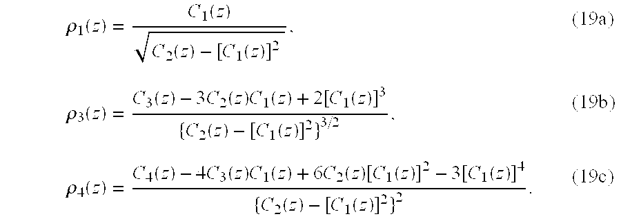
Then, inserting Equations (17a) and (18) into Equations (6) to (8) gives the probability distribution shape factors ρn. The results are ρ 1 ( z ) = C 1 ( z ) C 2 ( z ) - [ C 1 ( z ) ] 2 , (19a) ρ 3 ( z ) = C 3 ( z ) - 3 C 2 ( z ) C 1 ( z ) + 2 [ C 1 ( z ) ] 3 { C 2 ( z ) - [ C 1 ( z ) ] 2 } 3 / 2 , (19b) ρ 4 ( z ) = C 4 ( z ) - 4 C 3 ( z ) C 1 ( z ) + 6 C 2 ( z ) [ C 1 ( z ) ] 2 - 3 [ C 1 ( z ) ] 4 { C 2 ( z ) - [ C 1 ( z ) ] 2 } 2 . (19c)
Figure US06304594-20011016-M00021
Equations (19) are plotted in FIGS. 7 to 9.
The Rice distribution is known to approach the Rayleigh distribution as z→0, and to approach a Gaussian distribution for large z. Note in FIGS. 7 to 9 that the curves for ρn have the values given in Equations (13) for the Rayleigh distribution at z=0. For large values of z, the kurtosis, ρ4, approaches the limiting value of 3, as for a Gaussian distribution. Similarly, the skewness, ρ3, approaches 0, indicating that the distribution is becoming more symmetric, like a Gaussian distribution. For small z, ρ3 is large, indicating that the distribution is highly asymmetric.
It appears from FIGS. 7 to 9 that a reasonable test as to whether a CW interferer is present in the data, and corrupting the constellation, is to calculate the ratios {overscore (ρ)}1, {overscore (ρ)}3, and {overscore (ρ)}4, for the observed data averaged over all symbol clusters, and compare the values with FIGS. 7 to 9. If {overscore (ρ)}1>2.10, {overscore (ρ)}3<0.50, and {overscore (ρ)}4<3.10, one can be reasonably certain that the radial probability distribution of points in the clusters is not Rayleigh, and that there is probably an interferer present. Based upon the curves in these figures, if a single parameter were to be used to make this decision, it should be the skewness, {overscore (ρ)}3, which exhibits a rapid and monotonic departure from the Rayleigh value at z=0. However, the kurtosis, {overscore (ρ)}4, also exibits a useful distinction between large values for small z (small or no interferers) and smaller values for large z (large interferers), although the kurtosis function is not monotonic.
To check the validity of this approach, a number of simulations were run for a range of input CNRs and a range of interferer amplitudes, where the amplitude a was normalized to the noise margin d, and the normalized interferer amplitude was varied over the range 0.000001≦a/d≦0.5. Although most runs were done with an amplitude spread of 0 on the interferer (no amplitude modulation), some runs were also done with a uniformly distributed amplitude spread of 0.1 to represent a modest amplitude distribution. Similar results were obtained with and without the amplitude modulation. The results of these simulations showed a strong correlation between the cluster skewness {overscore (ρ)}3 and the calculated carrier-to-interference ratio (CIR), and a somewhat weaker correlation between the cluster kurtosis {overscore (ρ)}4 and the CIR. The distribution shape parameter {overscore (ρ)}1 showed a much poorer correlation with the CIR. This prediction that the cluster skewness is the best single predictor of the presence of an interferer was subsequently confirmed by tests on a developmental VDSL modem that had the capability to make the various measurements and tests. Consequently, although both the skewness and kurtosis are shown in Step 54 of the procedure in FIG. 2, the skewness is the preferred parameter if just one is to be calculated.
To calculate the skewness in Step 54, the symbol coordinates for each sample symbol in each cell m are adjusted by subtracting the sample mean coordinates {overscore (x)}m and {overscore (y)}m to form the coordinate differences from the cluster center, xmk−{overscore (x)}m and ymk−{overscore (y)}m Then the radial distance of each sample from its cluster center, r mk = ( x mk - x _ m ) 2 + ( y mk - y _ m ) 2 , ( 20 )
Figure US06304594-20011016-M00022
is calculated. If there is no distortion of the constellation, so that the expected values of the sample mean coordinates {overscore (x)}m and {overscore (y)}m coincide with the ideal locations of the cluster centers, then the sample means in Equation 20 may be replaced by the ideal cluster coordinates. This also eliminates statistical fluctuations in the calculated cluster mean coordinates.
Next, within Step 54, the sample moments s n = 1 MN m = 1 M k = 1 N m r mk n , n = 1 , , 4 ,
Figure US06304594-20011016-M00023
are calculated, where Nm is the number of data symbol samples in the bin for symbol cell m, accumulated previously in Step 48, and N is the total number of data symbol samples in all bins. Analogous to Equations (9), the second and third central moments are then calculated by
s 2 =s′ 2 −s′ 1 2,
s 3 =s′ 3−3s′ 2 s′ 1+2s′ 1 3
The cluster skewness is then calculated by
{overscore (ρ)} 3 =s 3/(s 2 3/2.
Similarly, to calculate the kurtosis in Step 54, the fourth central moment is calculated by
s 4 =s′ 4−4s′ 3 s′ 1+6s′ 2 s′ 1 2−3s′ 1 4,
and the cluster kurtosis is then calculated by
{overscore (ρ)}4 =s 4 /s 2 2.
To determine whether an interferer is present, the calculated skewness and/or kurtosis is compared, in Step 56, with a threshold level determined from FIG. 8 or 9, respectively. As seen from FIG. 8, a skewness less than about 0.50 indicates that the cluster radial distribution is Ricean distributed, indicating that an interferer is present, while a skewness greater than this value indicates a Rayleigh distribution, indicating that no interferer is present. Similarly, from FIG. 9 it is seen that a kurtosis less than about 3.15 indicates that the cluster radial distribution is Ricean distributed, indicating that an interferer is present, while a kurtosis greater than this value indicates a Rayleigh distribution, indicating that no interferer is present. In experiments on the developmental VDSL modem, a skewness threshold of 0.3 to 0.5 and a kurtosis threshold of 3.12 to 3.15 have been found to be optimum. However, the lower the CNR of the input signal, i.e., the higher the noise level, the stronger the interferer must generally be to detect it above the noise. Of course, the smaller the interference-to-noise ratio (INR) is, the less proportionate effect the interferer has on the overall SER. When the cluster skewness is plotted as a function of both the CNR and the normalized interferer amplitude, as in FIG. 10 (which was generated for a 4-QAM signal), it is found that, except for some anomalous behavior in the vicinity of CNRs from 15 to 20 dB (which is reproducible, but of undetermined cause), a given skewness threshold level can only detect larger amplitude interferers as the CNR decreases. Similarly jagged and anomalous results have been found when using the cluster kurtosis as the interference detection measure, as shown in FIG. 11. With either approach, neither the skewness nor the kurtosis can be used to determine the interferer's amplitude. But either can be used to determine whether an interferer with amplitude significantly (more so for kurtosis than for skewness) higher than that corresponding to that of the test criterion is present (except at low input CNRs and high interferer amplitudes where the contours of skewness or kurtosis versus CNR are essentially vertical). Within these limits, for any CNR, a skewness and/or kurtosis threshold can be selected to determine whether an interferer with amplitude greater than a specified level is present. For high noise and strong interferers, the combined effect is to expand the size of the symbol clusters so much that they overlap, at which point determination of CNR, SER, and cluster skewness and kurtosis from constellation analysis is no longer possible. Also, when there is much noise (low CNR), the resulting statistical fluctuations cause some uncertainty in the calculated skewness and kurtosis, reducing the significance of the threshold decision. Nevertheless, at moderate and high CNRs, the method works quite well, and has been found valuable in detecting weak interferers.
Note from FIG. 7 that the quantity {overscore (ρ)}1=s′1/{square root over (s2+L )} has a unique value for any value of the quantity z given in Equation (16), which is the INR. Therefore, if it has been concluded that an interferer is present, the value of {overscore (ρ)}1 may be calculated, and the corresponding value of z may be looked up in a tabulated version of FIG. 7 to obtain an estimate of the INR for diagnostic purposes.
When the skewness and/or kurtosis test 56 has found the presence of an interferer, the computer 76 sends a notification message via reverse control channel 58 to transmitter controller 60. Transmitter controller 60 then interrupts the input bit stream 20 and turns off the power amplifier 28, so that the only input to the receiver 18 is the external interference 32. Meanwhile, the computer 76 also sends a notification message to receiver controller 62, which sets the carrier frequency and symbol rate synchronizers to flywheel, opens both poles of switch 64, and closes switch 70, so that the received external interference 32 goes (through an amplifier, not shown) to the analog-to-digital conversion 78 and spectrum analysis 74. The receiver controller 62 also sends an acknowledgment to the transmitter controller 60 that the receiver 18 is temporarily ceasing to process received digital data while the computer is performing the spectrum analysis. The transmitter controller 60 does not turn off the transmitter 16 until this acknowledgment is received. Simultaneously, the computer 76 switches its operation entirely over to spectrum analysis 74. The results of the spectrum analysis are sent via reverse control channel 58 to transmitter controller 60 which analyzes the received spectrum to find a carrier frequency at which the desired data rate may be transferred without encountering any interference. If no pass band of sufficient width is available, the transmitter controller 60 will switch transmission to a higher order constellation with a lower symbol rate, providing that such a combination is available that can provide the desired bit rate, and provided that the noise margin in the new constellation is adequate to provide the required BER. If these conditions cannot be met, the transmitter controller 60 will attempt to reduce the transmitted bit rate with the same or larger constellation in order to reduce the transmitted bandwidth, providing that the information to be transmitted will not be impaired by a reduced bit rate, as would some types of real-time transmissions.
After selecting a new carrier frequency, constellation size, and/or symbol rate, the transmitter controller 60 inserts a control message into the input bit stream 20 to transmit over the forward transmission channel 30 to the receiver 18. The receiver controller 62 extracts this message out of the output bit stream 46 and then sets the receiver 18 to receive and demodulate a signal with these new parameters. The receiver controller 62 also sends an acknowledgment of the receipt of this control message over the reverse control channel 58 to the transmitter controller 60. Only after receiving this acknowledgment does the transmitter controller 60 actually change the transmitter parameters to the new values.
At this point, receiver controller 62 also opens switch 70, closes both poles of switch 64, and directs computer 76 to switch back to accumulating statistics on the new received symbol stream: calculating the CNR and BER; testing the BER; and, if necessary; calculating and testing the skewness and/or kurtosis on the new received constellation.
While the invention has been particularly shown and described with reference to preferred embodiments thereof, it will be understood by those skilled in the art that various changes in form and details may be made therein without departing from the spirit and scope of the invention. Changes in future embodiments of the invention can therefore be made without departing from the teachings herein.

Claims (26)

What is claimed is:
1. In a communication apparatus, a method of detecting whether an interference signal is being received with a received signal of interest (SOI), said method being non-intrusive to a continued reception of the SOI and comprising steps of:
(a) accumulating statistical information associated with said SOI;
(b) determining whether an intrusive interference signal is present with said SOI, said step further comprising substeps of:
(i) determining a root mean square (RMS) cluster size of said intrusive interference signal;
(ii) determining a reciprocal constellation closure of said intrusive interference signal; and
(iii) determining a carrier-to-noise ratio (CNR) of said intrusive interference signal;
(c) analyzing, when an intrusive interference signal is present, said intrusive interference signal to determine the frequency thereof;
(d) identifying a spectral region free of interferers; and
(e) adjusting said communication apparatus to operate in said spectral region identified in step (d).
2. The method of claim 1 wherein said step (b) further comprises determining a symbol error rate of said intrusive interference signal.
3. The method of claim 1 wherein said step (b) further comprises determining a bit error rate of said intrusive interference signal.
4. The method of claim 1 wherein said step (b) further comprises determining an average cluster skewness associated with said intrusive interference signal.
5. The method of claim 1 wherein said step (b) further comprises determining an average cluster kurtosis associated with said intrusive interference signal.
6. A transceiver for transmitting and receiving data signals, said transceiver being capable of non-intrusively detecting an interference signal to said data signals, said transceiver comprising:
storage means for accumulating statistical information associated with said data signals;
interference determining means for determining whether an unacceptable interference signal is present with said data signals;
analysis means for spectrum analyzing said unacceptable interference signal and determining a frequency thereof and further locating a spectral region free of interferers;
conveyance means for communicating to a transmitter said spectral region free of interferers; and
means responsive to said conveyance means for changing operation of the transceiver and transmitter to said spectral region free of interferers.
7. The transceiver of claim 6 wherein said interference signal is a continuous wave signal.
8. The transceiver of claim 7 wherein said transceiver uses quadrature amplitude modulation.
9. The transceiver of claim 7 wherein said transceiver uses carrierless AM/PM data communication methods.
10. The transceiver according to claim 7 wherein said storage means accumulates both presliced quadrature amplitude coordinates and sliced symbol cell identification data.
11. The transceiver according to claim 10 wherein said analysis means processes a sequence of demodulated symbols to calculate the statistics of in-phase and quadrature mean coordinates and in-phase and quadrature sample variances for a subset of symbols in each decision cell from said sequence of demodulated symbols, said sliced data being used to assign said presliced data to a proper symbol cell.
12. The transceiver according to claim 11 wherein said analysis means further determines from said statistics a root mean square (RMS) cluster size for all the symbol clusters in a constellation, a constellation closure, a resulting carrier-to-noise-ratio, a resulting symbol error rate, and a resulting bit error rate (BER).
13. The transceiver according to claim 12 wherein said analysis means further tests the magnitude of said bit error rate to determine whether the quality of said demodulated signal is above an acceptable threshold and if not, then directing the commencement of further processing to determine whether the degradation of the quality of said demodulated signal is due to the presence of said continuous wave interfering signal.
14. The Transceiver according to claim 12 wherein said analysis means determines an average cluster skewness for the symbol clusters in said constellation and tests the magnitude of said skewness to decide whether an interferer is most likely present, which would be the cause of said degradation of said BER.
15. The transceiver according to claim 12 wherein said analysis means determines an average cluster kurtosis for the symbol clusters in said constellation and testing the magnitude of said kurtosis to decide whether an interferer is most likely present, which would be the cause of said degradation of said BER.
16. The transceiver according to claim 14, wherein said conveyance means transmits the results of said test of skewness back to said transmitter over a reverse channel, said transmitter temporarily turning off transmission while said receiver receives only the external interference signals in the RF environment, and spectrum analyzing said environment to determine the frequencies of said interference signals.
17. The transceiver according to claim 15 wherein said conveyance means transmits the results of said test of kurtosis back to said transmitter over a reverse channel, said transmitter temporarily turning off transmission while said receiver receives only the external interference signals in the RF environment, and spectrum analyzing said environment to determine the frequencies of said interference signals.
18. The transceiver according to claim 16 wherein said conveyance means transmits the results of said spectrum analysis back to said transmitter over a reverse channel, said transmitter determining new transmission parameters to avoid said interference signals, and said transmitter transmitting said new transmission parameters to said transceiver.
19. The transceiver according to claim 18 wherein said transceiver and said transmitter reconfigure to transmit and receive the desired data signals with said new transmission parameters and then resuming data transmission using said new transmission parameters.
20. The transceiver according to claim 18 wherein said new transmission parameters include a new carrier frequency, QAM modulation order, and data rate.
21. The transceiver according to claim 7 wherein said transceiver uses quadrature partial response modulation.
22. A modem capable of non-intrusively detecting an unwanted interferer during a receiving of a data signal, comprising:
a transmitter for transmitting information to a communications apparatus;
a receiver for receiving said data signal from said communication apparatus;
a memory coupled to said receiver for storing statistical information associated with said data signal; and
a processor for measuring constellation statistics from said statistical information, determining a carrier-to-noise ratio and bit error rate of said data signal, determining whether a continuous wave or narrowband interferer is present, determining whether said bit error rate exceeds an acceptable limit by testing whether a symbol cluster changes from a Rayleigh distribution to a Ricean distribution, and when said bit error rate exceeds said acceptable limit, interrupting said received data signal to spectrum analyze a transmission band for an interference free region of said transmission band and communicating said interference free region to said communications apparatus for adjustment.
23. The modem according to claim 22 wherein said testing comprises calculating a skewness associated with said symbol cluster.
24. The modem according to claim 22 wherein said testing comprises calculating a kurtosis associated with said symbol cluster.
25. The modem according to claim 21 further comprising an analog-to-digital converter coupled for converting said data signal into a digital signal.
26. The modem according to claim 23 further comprising a fast-Fourier-transform-analysis means for spectrum analyzing said analog signal.
US09/123,203 1998-07-27 1998-07-27 Interference detection and avoidance technique Expired - Lifetime US6304594B1 (en)

Priority Applications (7)

Application Number Priority Date Filing Date Title
US09/123,203 US6304594B1 (en) 1998-07-27 1998-07-27 Interference detection and avoidance technique
KR1020017001132A KR20010074771A (en) 1998-07-27 1999-07-26 Interference detection and avoidance technique
PCT/US1999/016864 WO2000007302A1 (en) 1998-07-27 1999-07-26 Interference detection and avoidance technique
EP99938803A EP1114519A4 (en) 1998-07-27 1999-07-26 Interference detection and avoidance technique
JP2000563008A JP2003528476A (en) 1998-07-27 1999-07-26 Method and apparatus for interference detection and avoidance
AU53208/99A AU5320899A (en) 1998-07-27 1999-07-26 Interference detection and avoidance technique
HK02100229.1A HK1040328A1 (en) 1998-07-27 2002-01-11 Interference detection and avoidance technique

Applications Claiming Priority (1)

Application Number Priority Date Filing Date Title
US09/123,203 US6304594B1 (en) 1998-07-27 1998-07-27 Interference detection and avoidance technique

Publications (1)

Publication Number Publication Date
US6304594B1 true US6304594B1 (en) 2001-10-16

Family

ID=22407276

Family Applications (1)

Application Number Title Priority Date Filing Date
US09/123,203 Expired - Lifetime US6304594B1 (en) 1998-07-27 1998-07-27 Interference detection and avoidance technique

Country Status (7)

Country Link
US (1) US6304594B1 (en)
EP (1) EP1114519A4 (en)
JP (1) JP2003528476A (en)
KR (1) KR20010074771A (en)
AU (1) AU5320899A (en)
HK (1) HK1040328A1 (en)
WO (1) WO2000007302A1 (en)

Cited By (53)

* Cited by examiner, † Cited by third party
Publication number Priority date Publication date Assignee Title
US20010028320A1 (en) * 2000-02-17 2001-10-11 Prendergast Colm J. Isolation system with analog communication across an isolation barrier
US20020007257A1 (en) * 1999-11-04 2002-01-17 Eilon Riess Reliable symbols as a means of improving the performance of information transmission systems
US20020027951A1 (en) * 2000-02-08 2002-03-07 Eamonn Gormley Real-time system for measuring the ricean K-factor
US20020037062A1 (en) * 1999-11-04 2002-03-28 Eilon Riess Reliable symbols as a means of improving the performance of information transmission systems
US20020080896A1 (en) * 1999-11-04 2002-06-27 Verticalband, Limited Fast, blind equalization techniques using reliable symbols
US6487243B1 (en) 1999-03-08 2002-11-26 International Business Machines Corporation Modems, methods, and computer program products for recovering from errors in a tone reversal sequence between two modems
US20020176364A1 (en) * 2001-05-25 2002-11-28 Ntt Docomo, Inc. Interference detection method and interference avoidance system for wireless communication links
US20020181604A1 (en) * 2001-04-27 2002-12-05 Chen Ernest C. Layered modulation for digital signals
US20020191703A1 (en) * 2001-03-23 2002-12-19 Fuyun Ling Method and apparatus for utilizing channel state information in a wireless communication system
US6553518B1 (en) * 1999-03-08 2003-04-22 International Business Machines Corporation Severe error detectors, methods and computer program products that use constellation specific error event thresholds to detect severe error events during demodulation of a signal comprising symbols from a plurality of symbol constellations
US6556366B2 (en) * 1998-11-04 2003-04-29 Stmicroelectronics, Inc. Bimodal biasing of magneto resistive heads
US20030083852A1 (en) * 2001-10-26 2003-05-01 Khurram Muhammad Active removal of aliasing frequencies in a decimating structure by changing a decimation ratio in time and space
US20030118128A1 (en) * 2001-12-20 2003-06-26 Qilian Liang Method, system, device and computer program product for a demodulator with communications link adaptation
US20030171900A1 (en) * 2002-03-11 2003-09-11 The Charles Stark Draper Laboratory, Inc. Non-Gaussian detection
US20030185319A1 (en) * 2002-03-30 2003-10-02 Kolze Thomas J. Modified branch metrics for processing soft decisions to account for phase noise impact on cluster variance
US6661847B1 (en) 1999-05-20 2003-12-09 International Business Machines Corporation Systems methods and computer program products for generating and optimizing signal constellations
US6661849B1 (en) * 2000-03-28 2003-12-09 Advanced Micro Devices, Inc. Multiple payload slicer system with prenormalization integer values
US6661837B1 (en) 1999-03-08 2003-12-09 International Business Machines Corporation Modems, methods, and computer program products for selecting an optimum data rate using error signals representing the difference between the output of an equalizer and the output of a slicer or detector
US20040101035A1 (en) * 2002-11-27 2004-05-27 Jan Boer Data transmission rate adaptation in a wireless communication system
US20040100328A1 (en) * 2000-08-30 2004-05-27 Cirrus Logic, Inc. Circuits and methods for reducing interference from switched mode circuits
KR100441196B1 (en) * 2002-01-14 2004-07-21 기가텔레콤 (주) Apparatus for continuous phase quadrature amplitude modulation and demodulation
US20040264591A1 (en) * 2003-06-30 2004-12-30 Telefonaktiebolaget Lm Ericsson (Publ) Method and system for M-QAM detection in communication systems
US6931074B1 (en) * 2000-08-28 2005-08-16 General Dynamics Decision Systems, Inc. Transmitter having programmable transmission parameters temporally aligned with payload and method therefor
US20050281200A1 (en) * 2004-06-16 2005-12-22 Gerard Terreault QAM signal analysis in a network
EP1624598A1 (en) * 2004-08-05 2006-02-08 The Directv Group, Inc. Carrier to noise ratio estimations from a received signal
US7003030B2 (en) 1999-03-08 2006-02-21 Lenovo (Singapore) Pte. Ltd. Receivers, methods, and computer program products for an analog modem that receives data signals from a digital modem
US20060056283A1 (en) * 2001-09-05 2006-03-16 Santosh Anikhindi Interference mitigation in a wireless communication system
US20060215537A1 (en) * 2005-02-24 2006-09-28 Wen-Rong Wu Apparatus and method for estimating a clipping parameter of an ofdm system
US7173981B1 (en) 2001-04-27 2007-02-06 The Directv Group, Inc. Dual layer signal processing in a layered modulation digital signal system
US7184473B2 (en) 2001-04-27 2007-02-27 The Directv Group, Inc. Equalizers for layered modulated and other signals
US7245671B1 (en) 2001-04-27 2007-07-17 The Directv Group, Inc. Preprocessing signal layers in a layered modulation digital signal system to use legacy receivers
US20080037665A1 (en) * 2006-05-24 2008-02-14 Akira Maeki Radio communication apparatus for controlling bandwidth of channel
US20090149133A1 (en) * 2007-11-02 2009-06-11 Kabushiki Kaisha Toshiba Communication apparatus and program for identifying faults and computer program storage medium
US20090214201A1 (en) * 2008-02-22 2009-08-27 Fujitsu Limited Monitor circuit for monitoring property of optical fiber transmission line and quality of optical signal
US20090245392A1 (en) * 2006-12-12 2009-10-01 Leung Raymond W K Method and system for concealing errors
US7706466B2 (en) 2001-04-27 2010-04-27 The Directv Group, Inc. Lower complexity layered modulation signal processor
US7738587B2 (en) 2002-07-03 2010-06-15 The Directv Group, Inc. Method and apparatus for layered modulation
US7822154B2 (en) 2001-04-27 2010-10-26 The Directv Group, Inc. Signal, interference and noise power measurement
US7920643B2 (en) 2001-04-27 2011-04-05 The Directv Group, Inc. Maximizing power and spectral efficiencies for layered and conventional modulations
US8005035B2 (en) 2001-04-27 2011-08-23 The Directv Group, Inc. Online output multiplexer filter measurement
US8019029B1 (en) 2007-06-26 2011-09-13 Pmc-Sierra, Inc. Interference erasure using soft decision weighting of the Viterbi decoder input in OFDM systems
US8208526B2 (en) 2001-04-27 2012-06-26 The Directv Group, Inc. Equalizers for layered modulated and other signals
US8259641B2 (en) 2001-04-27 2012-09-04 The Directv Group, Inc. Feeder link configurations to support layered modulation for digital signals
US20140074867A1 (en) * 2012-09-12 2014-03-13 Siemens Industry, Inc. Methods and systems for evaluating the performance of building processes
US20140074797A1 (en) * 2012-09-12 2014-03-13 Siemens Industry, Inc. Methods and systems for generating a business process control chart for monitoring building processes
US20140269341A1 (en) * 2013-03-14 2014-09-18 Don Gunasekara Wireless signal interference mitigation in a network
EP2922224A4 (en) * 2012-12-18 2015-12-02 Zte Corp Apparatus and method for detecting frequency spectrum interference
CN105589063A (en) * 2016-01-12 2016-05-18 中国海洋大学 Impulse radio 60 GHz ranging method based on skewness
US20160285654A1 (en) * 2013-11-12 2016-09-29 Telefonaktiebolaget Lm Ericsson (Publ) Improved adjacent channel interference protection
US20180070254A1 (en) * 2016-09-08 2018-03-08 Commscope Technologies Llc Interference detection and identification in wireless network from rf or digitized signal
US10608919B2 (en) 2016-02-19 2020-03-31 Commscope Technologies Llc Passive intermodulation (PIM) testing in distributed base transceiver station architecture
USRE48134E1 (en) 2013-01-14 2020-07-28 Commscope Technologies Llc Interceptor system for characterizing digital data in telecommunication system
CN113242106A (en) * 2021-05-10 2021-08-10 深圳正江信通科技有限公司 Radio communication interference device and adaptive interference method

Families Citing this family (10)

* Cited by examiner, † Cited by third party
Publication number Priority date Publication date Assignee Title
US7460835B1 (en) * 2000-09-22 2008-12-02 Arraycomm Llc Method and apparatus for determining an operating condition in a communications system
DE10130687A1 (en) * 2001-06-26 2003-01-02 Rohde & Schwarz Measuring system with a reference signal between a signal generator and a signal analyzer
US7274731B2 (en) * 2001-11-09 2007-09-25 Adc Dsl Systems, Inc. Non-chronological system statistics
US20050153703A1 (en) * 2003-12-31 2005-07-14 Markku Juntti Method of allocating resources in telecommunications system transceiver, computer program, and telecommunications system
RU2371867C2 (en) 2004-10-20 2009-10-27 Квэлкомм Инкорпорейтед Operation in many frequency ranges of wireless networks
US7983298B2 (en) 2004-10-20 2011-07-19 Qualcomm Incorporated Multiple frequency band operation in wireless networks
EP2048801B1 (en) * 2007-10-11 2012-08-08 Promax Electronica, S.L. Method for identifying and diagnosing interferences in RF signals and particularly television signals
ES2324693B1 (en) * 2007-10-11 2010-07-07 Promax Electronica, S.A. METHOD AND APPLIANCE FOR THE IDENTIFICATION AND DIAGNOSIS OF INTERFERENCES IN RF SIGNALS, IN PARTICULAR TELEVISION SIGNALS.
KR101034949B1 (en) * 2008-11-21 2011-05-17 성균관대학교산학협력단 Method of analyzing performance of css system in the presence of tone jamming signal
EP2390679B1 (en) * 2010-05-27 2012-10-03 Mitsubishi Electric R&D Centre Europe B.V. Automotive radar with radio-frequency interference avoidance

Citations (48)

* Cited by examiner, † Cited by third party
Publication number Priority date Publication date Assignee Title
US3940694A (en) 1971-10-29 1976-02-24 Sperry Rand Corporation Apparatus and method for reducing multiplicative gain variation distortions in data recording and transmission channels
US4291277A (en) 1979-05-16 1981-09-22 Harris Corporation Adaptive predistortion technique for linearizing a power amplifier for digital data systems
US4462001A (en) 1982-02-22 1984-07-24 Canadian Patents & Development Limited Baseband linearizer for wideband, high power, nonlinear amplifiers
US4555790A (en) 1983-06-30 1985-11-26 Betts William L Digital modem having a monitor for signal-to-noise ratio
US4587498A (en) 1983-03-07 1986-05-06 Telecummunications Radioelectriques et Telephoniques T.R.T. Circuit for recovering the carrier of an amplitude-and-phase-modulated input signal
US4615038A (en) 1984-06-06 1986-09-30 At&T Information Systems Inc. Equalization of modulated data signals utilizing tentative and final decisions and replication of non-linear channel distortion
US4731816A (en) 1985-05-20 1988-03-15 Telebit Corporation Ensemble modem structure for imperfect transmission media
US4805191A (en) 1987-11-25 1989-02-14 Motorola, Inc. Modem with improved timing recovery using equalized data
US4827431A (en) 1987-01-20 1989-05-02 General Datacomm, Inc. Methods and systems for the simultaneous quantitative measurement of phase and amplitude jitter impairments and signal to noise ratio in a qam data communication channel
US4890300A (en) 1987-04-28 1989-12-26 Racal Communications Equipment Limited Radio transmitters
US4980897A (en) 1988-08-12 1990-12-25 Telebit Corporation Multi-channel trellis encoder/decoder
US4995057A (en) 1988-11-02 1991-02-19 At&T Bell Laboratories Technique for achieving the theoretical coding gain of digital signals incorporating error correction
US5105445A (en) 1989-10-06 1992-04-14 U.S. Philips Corporation Predistortion arrangement for a digital transmission system
US5107520A (en) 1989-01-24 1992-04-21 U.S. Philips Corporation Adaptive predistortion circuit for a digital transmission system
US5113414A (en) 1989-10-06 1992-05-12 U.S. Philips Corporation Predistortion arrangement for a digital transmission system
US5148448A (en) 1989-03-14 1992-09-15 U.S. Philips Corporation Adaptive predistortion circuit with memory
US5166924A (en) * 1990-03-06 1992-11-24 Mercury Digital Communications, Inc. Echo cancellation in multi-frequency differentially encoded digital communications
US5249200A (en) 1991-07-30 1993-09-28 Codex Corporation Device and method for combining precoding with symbol-rate spectral shaping
US5285474A (en) 1992-06-12 1994-02-08 The Board Of Trustees Of The Leland Stanford, Junior University Method for equalizing a multicarrier signal in a multicarrier communication system
US5295138A (en) 1992-04-21 1994-03-15 Northwest Starscon Limited Partnership Apparatus and method for optimal frequency planning in frequency division multiplexing transmissions
US5313467A (en) 1989-11-15 1994-05-17 Digital Equipment Corporation Integrated communication link having a dynamically allocatable bandwidth and protocol for transmission of allocation information over the link
US5339054A (en) 1992-07-01 1994-08-16 Nec Corporation Modulated signal transmission system compensated for nonlinear and linear distortion
US5394392A (en) 1992-12-14 1995-02-28 At&T Corp. Method for transferring information using modems
US5479447A (en) 1993-05-03 1995-12-26 The Board Of Trustees Of The Leland Stanford, Junior University Method and apparatus for adaptive, variable bandwidth, high-speed data transmission of a multicarrier signal over digital subscriber lines
US5491726A (en) * 1993-08-17 1996-02-13 Tcsi Corp. Method and apparatus to determine the frequency and time slot position in a digital wireless communication session
US5497505A (en) 1990-10-25 1996-03-05 Northern Telecom Limited Call set-up and spectrum sharing in radio communication on systems with dynamic channel allocation
US5519356A (en) 1995-02-13 1996-05-21 National Semiconductor Corporation Methods and apparatuses for fast decision directed carrier recovery with wide locking range
US5519731A (en) * 1994-04-14 1996-05-21 Amati Communications Corporation ADSL compatible discrete multi-tone apparatus for mitigation of T1 noise
US5541955A (en) * 1992-11-06 1996-07-30 Pericle Communications Company Adaptive data rate modem
US5548809A (en) 1992-07-15 1996-08-20 Southwestern Bell Technology Resources, Inc. Spectrum sharing communications system and system for monitoring available spectrum
US5551057A (en) * 1994-06-08 1996-08-27 Lucent Technologies Inc. Cellular mobile radio system power control
US5572553A (en) 1994-03-16 1996-11-05 Alcatel Telspace Digital apparatus for broadband carrier-recovery
US5606577A (en) 1995-01-26 1997-02-25 Motorola Inc. Method and apparatus for a DMT transmitter having a data for matter coupled directly to a constellation encoder
US5621767A (en) 1994-09-30 1997-04-15 Hughes Electronics Method and device for locking on a carrier signal by dividing frequency band into segments for segment signal quality determination and selecting better signal quality segment
US5694440A (en) 1996-01-02 1997-12-02 Motorola, Inc. Data synchronizer lock detector and method of operation thereof
US5705958A (en) 1995-09-27 1998-01-06 Alcatel Telspace Apparatus for correcting quadrature error in a modulator and/or in a demodulator for a signal having a plurality of phase states, a corresponding transmitter, and a corresponding receiver
US5710766A (en) 1995-12-26 1998-01-20 Motorola, Inc. Method and apparatus for sharing a common bandwidth between two protocols in a radio communication system
US5726978A (en) 1995-06-22 1998-03-10 Telefonaktiebolaget L M Ericsson Publ. Adaptive channel allocation in a frequency division multiplexed system
US5732333A (en) 1996-02-14 1998-03-24 Glenayre Electronics, Inc. Linear transmitter using predistortion
US5742639A (en) * 1994-05-13 1998-04-21 Westinghouse Electric Corporation Mobile terminal apparatus and method for a satellite communication system
US5751741A (en) * 1996-11-20 1998-05-12 Motorola, Inc. Rate-adapted communication system and method for efficient buffer utilization thereof
US5751766A (en) 1995-04-27 1998-05-12 Applied Signal Technology, Inc. Non-invasive digital communications test system
US5765113A (en) * 1994-12-29 1998-06-09 Russo; David William Method and apparatus for avoiding desensitization of a radio frequency receiver
US5781582A (en) * 1995-05-04 1998-07-14 Interwave Communications International Ltd. Frequency agile transceiver with multiple frequency synthesizers per transceiver
US5812594A (en) * 1994-10-14 1998-09-22 Rakib; Selim Method and apparatus for implementing carrierless amplitude/phase encoding in a network
US5911120A (en) * 1995-09-08 1999-06-08 At&T Wireless Services Wireless communication system having mobile stations establish a communication link through the base station without using a landline or regional cellular network and without a call in progress
US6055268A (en) * 1996-05-09 2000-04-25 Texas Instruments Incorporated Multimode digital modem
US6075797A (en) * 1997-10-17 2000-06-13 3Com Corporation Method and system for detecting mobility of a wireless-capable modem to minimize data transfer rate renegotiations

Family Cites Families (8)

* Cited by examiner, † Cited by third party
Publication number Priority date Publication date Assignee Title
JP2694138B2 (en) * 1988-07-22 1997-12-24 日本電信電話株式会社 Mobile communication channel switching method
US5668828A (en) * 1992-05-08 1997-09-16 Sanconix, Inc. Enhanced frequency agile radio
US5311541A (en) * 1992-05-08 1994-05-10 Axonn Corporation Frequency agile radio
JPH06343066A (en) * 1993-06-01 1994-12-13 Nippon Telegr & Teleph Corp <Ntt> Spread spectrum radio communications system
JPH0715391A (en) * 1993-06-24 1995-01-17 Sharp Corp Radio communications equipment
JPH07212833A (en) * 1994-01-17 1995-08-11 Matsushita Electric Ind Co Ltd Radio communication equipment
JPH08317000A (en) * 1995-05-17 1996-11-29 Kyocera Corp Line quality detector
JPH09168182A (en) * 1995-12-18 1997-06-24 Matsushita Electric Ind Co Ltd Mobile telephone system and its interference evading method

Patent Citations (49)

* Cited by examiner, † Cited by third party
Publication number Priority date Publication date Assignee Title
US3940694A (en) 1971-10-29 1976-02-24 Sperry Rand Corporation Apparatus and method for reducing multiplicative gain variation distortions in data recording and transmission channels
US4291277A (en) 1979-05-16 1981-09-22 Harris Corporation Adaptive predistortion technique for linearizing a power amplifier for digital data systems
US4462001A (en) 1982-02-22 1984-07-24 Canadian Patents & Development Limited Baseband linearizer for wideband, high power, nonlinear amplifiers
US4587498A (en) 1983-03-07 1986-05-06 Telecummunications Radioelectriques et Telephoniques T.R.T. Circuit for recovering the carrier of an amplitude-and-phase-modulated input signal
US4555790A (en) 1983-06-30 1985-11-26 Betts William L Digital modem having a monitor for signal-to-noise ratio
US4615038A (en) 1984-06-06 1986-09-30 At&T Information Systems Inc. Equalization of modulated data signals utilizing tentative and final decisions and replication of non-linear channel distortion
US4731816A (en) 1985-05-20 1988-03-15 Telebit Corporation Ensemble modem structure for imperfect transmission media
US4827431A (en) 1987-01-20 1989-05-02 General Datacomm, Inc. Methods and systems for the simultaneous quantitative measurement of phase and amplitude jitter impairments and signal to noise ratio in a qam data communication channel
US4890300A (en) 1987-04-28 1989-12-26 Racal Communications Equipment Limited Radio transmitters
US4805191A (en) 1987-11-25 1989-02-14 Motorola, Inc. Modem with improved timing recovery using equalized data
US4980897A (en) 1988-08-12 1990-12-25 Telebit Corporation Multi-channel trellis encoder/decoder
US4995057A (en) 1988-11-02 1991-02-19 At&T Bell Laboratories Technique for achieving the theoretical coding gain of digital signals incorporating error correction
US5107520A (en) 1989-01-24 1992-04-21 U.S. Philips Corporation Adaptive predistortion circuit for a digital transmission system
US5148448A (en) 1989-03-14 1992-09-15 U.S. Philips Corporation Adaptive predistortion circuit with memory
US5105445A (en) 1989-10-06 1992-04-14 U.S. Philips Corporation Predistortion arrangement for a digital transmission system
US5113414A (en) 1989-10-06 1992-05-12 U.S. Philips Corporation Predistortion arrangement for a digital transmission system
US5313467A (en) 1989-11-15 1994-05-17 Digital Equipment Corporation Integrated communication link having a dynamically allocatable bandwidth and protocol for transmission of allocation information over the link
US5166924A (en) * 1990-03-06 1992-11-24 Mercury Digital Communications, Inc. Echo cancellation in multi-frequency differentially encoded digital communications
US5497505A (en) 1990-10-25 1996-03-05 Northern Telecom Limited Call set-up and spectrum sharing in radio communication on systems with dynamic channel allocation
US5249200A (en) 1991-07-30 1993-09-28 Codex Corporation Device and method for combining precoding with symbol-rate spectral shaping
US5295138A (en) 1992-04-21 1994-03-15 Northwest Starscon Limited Partnership Apparatus and method for optimal frequency planning in frequency division multiplexing transmissions
US5285474A (en) 1992-06-12 1994-02-08 The Board Of Trustees Of The Leland Stanford, Junior University Method for equalizing a multicarrier signal in a multicarrier communication system
US5339054A (en) 1992-07-01 1994-08-16 Nec Corporation Modulated signal transmission system compensated for nonlinear and linear distortion
US5548809A (en) 1992-07-15 1996-08-20 Southwestern Bell Technology Resources, Inc. Spectrum sharing communications system and system for monitoring available spectrum
US5541955A (en) * 1992-11-06 1996-07-30 Pericle Communications Company Adaptive data rate modem
US5394392A (en) 1992-12-14 1995-02-28 At&T Corp. Method for transferring information using modems
US5479447A (en) 1993-05-03 1995-12-26 The Board Of Trustees Of The Leland Stanford, Junior University Method and apparatus for adaptive, variable bandwidth, high-speed data transmission of a multicarrier signal over digital subscriber lines
US5491726A (en) * 1993-08-17 1996-02-13 Tcsi Corp. Method and apparatus to determine the frequency and time slot position in a digital wireless communication session
US5572553A (en) 1994-03-16 1996-11-05 Alcatel Telspace Digital apparatus for broadband carrier-recovery
US5519731A (en) * 1994-04-14 1996-05-21 Amati Communications Corporation ADSL compatible discrete multi-tone apparatus for mitigation of T1 noise
US5673290A (en) 1994-04-14 1997-09-30 Amati Communications Corporation ADSL compatible discrete multi-tone apparatus
US5742639A (en) * 1994-05-13 1998-04-21 Westinghouse Electric Corporation Mobile terminal apparatus and method for a satellite communication system
US5551057A (en) * 1994-06-08 1996-08-27 Lucent Technologies Inc. Cellular mobile radio system power control
US5621767A (en) 1994-09-30 1997-04-15 Hughes Electronics Method and device for locking on a carrier signal by dividing frequency band into segments for segment signal quality determination and selecting better signal quality segment
US5812594A (en) * 1994-10-14 1998-09-22 Rakib; Selim Method and apparatus for implementing carrierless amplitude/phase encoding in a network
US5765113A (en) * 1994-12-29 1998-06-09 Russo; David William Method and apparatus for avoiding desensitization of a radio frequency receiver
US5606577A (en) 1995-01-26 1997-02-25 Motorola Inc. Method and apparatus for a DMT transmitter having a data for matter coupled directly to a constellation encoder
US5519356A (en) 1995-02-13 1996-05-21 National Semiconductor Corporation Methods and apparatuses for fast decision directed carrier recovery with wide locking range
US5751766A (en) 1995-04-27 1998-05-12 Applied Signal Technology, Inc. Non-invasive digital communications test system
US5781582A (en) * 1995-05-04 1998-07-14 Interwave Communications International Ltd. Frequency agile transceiver with multiple frequency synthesizers per transceiver
US5726978A (en) 1995-06-22 1998-03-10 Telefonaktiebolaget L M Ericsson Publ. Adaptive channel allocation in a frequency division multiplexed system
US5911120A (en) * 1995-09-08 1999-06-08 At&T Wireless Services Wireless communication system having mobile stations establish a communication link through the base station without using a landline or regional cellular network and without a call in progress
US5705958A (en) 1995-09-27 1998-01-06 Alcatel Telspace Apparatus for correcting quadrature error in a modulator and/or in a demodulator for a signal having a plurality of phase states, a corresponding transmitter, and a corresponding receiver
US5710766A (en) 1995-12-26 1998-01-20 Motorola, Inc. Method and apparatus for sharing a common bandwidth between two protocols in a radio communication system
US5694440A (en) 1996-01-02 1997-12-02 Motorola, Inc. Data synchronizer lock detector and method of operation thereof
US5732333A (en) 1996-02-14 1998-03-24 Glenayre Electronics, Inc. Linear transmitter using predistortion
US6055268A (en) * 1996-05-09 2000-04-25 Texas Instruments Incorporated Multimode digital modem
US5751741A (en) * 1996-11-20 1998-05-12 Motorola, Inc. Rate-adapted communication system and method for efficient buffer utilization thereof
US6075797A (en) * 1997-10-17 2000-06-13 3Com Corporation Method and system for detecting mobility of a wireless-capable modem to minimize data transfer rate renegotiations

Non-Patent Citations (8)

* Cited by examiner, † Cited by third party
Title
Agazzi, O., Tzeng, C.-P.J., Messerchmitt, D.G., and Hodges, D.A., "Timing Recovery in Digital Subscriber Loops," IEEE Trans. on Communications, vol. COM-33, No. 6, pp. 558-569, Jun. 1985.
Brown, R., Sorbaba, M., Wang, T., Segev, R., Van Kerkhove, J.F., Mildonian, H., Hall, C., Zimmerman, G., Martinez, K., Pires, T.K., Mullaney, K., Zain, I., Young B., Gleichauf, P., Hohhof, K., "Draft Interface Specification for a CAP Based RADSL System", Jul. 1996.
Gardner, F.M., "A BPSK/ZPSK Timing-Error Detector for Sampled Receivers," IEEE Trans. on Communications, vol. COM-34, No. 5, pp. 423-429, May 1986.
Karam, G., and Sari, H., "A Data Predistortion Technique with Memory for QAM Radio Systems", IEEE Trans on Communications, vol. 39, No. 2, pp. 336-344, Feb. 1991.
Meyers, M.H., "Robust Control of Decision Directed Loops," IEEE CH2655-9/89/0000-1030, pp. 1030-1036, Sep. 1989.
Sari, H., Desperben, L., and Moridi, S., "A New Class of Frequency Detectors for Carrier Recovery in QAM Systems", IEEE CH2314-3/86/0000-0482, pp. 482-486, 1986.
Sari, Hikmet, and Said, Moridi, "New Phase and Frequency Detectors for Carrier Recovery in PSK and QAM Systems", IEEE Trans. on Communications, vol. 36, No. 9, pp. 1035-1043, Sep. 1988.
Suzuki, T. Takatori, H., Ogawa, M. and Tomooka, K., "Line Equalizer for a Digital Subscriber Loop Employing Switched Capacitor Technology," IEEE Trans on Communications, vol. COM-30, No. 9, pp. 2074-2082, Sep. 1982.

Cited By (87)

* Cited by examiner, † Cited by third party
Publication number Priority date Publication date Assignee Title
US6556366B2 (en) * 1998-11-04 2003-04-29 Stmicroelectronics, Inc. Bimodal biasing of magneto resistive heads
US7003030B2 (en) 1999-03-08 2006-02-21 Lenovo (Singapore) Pte. Ltd. Receivers, methods, and computer program products for an analog modem that receives data signals from a digital modem
US6487243B1 (en) 1999-03-08 2002-11-26 International Business Machines Corporation Modems, methods, and computer program products for recovering from errors in a tone reversal sequence between two modems
US6661837B1 (en) 1999-03-08 2003-12-09 International Business Machines Corporation Modems, methods, and computer program products for selecting an optimum data rate using error signals representing the difference between the output of an equalizer and the output of a slicer or detector
US6553518B1 (en) * 1999-03-08 2003-04-22 International Business Machines Corporation Severe error detectors, methods and computer program products that use constellation specific error event thresholds to detect severe error events during demodulation of a signal comprising symbols from a plurality of symbol constellations
US6661847B1 (en) 1999-05-20 2003-12-09 International Business Machines Corporation Systems methods and computer program products for generating and optimizing signal constellations
US20020080896A1 (en) * 1999-11-04 2002-06-27 Verticalband, Limited Fast, blind equalization techniques using reliable symbols
US7110923B2 (en) 1999-11-04 2006-09-19 Verticalband, Limited Fast, blind equalization techniques using reliable symbols
US7085691B2 (en) * 1999-11-04 2006-08-01 Verticalband, Limited Reliable symbols as a means of improving the performance of information transmission systems
US20020007257A1 (en) * 1999-11-04 2002-01-17 Eilon Riess Reliable symbols as a means of improving the performance of information transmission systems
US20030016769A9 (en) * 1999-11-04 2003-01-23 Verticalband, Limited Fast, blind equalization techniques using reliable symbols
US20020037062A1 (en) * 1999-11-04 2002-03-28 Eilon Riess Reliable symbols as a means of improving the performance of information transmission systems
US7143013B2 (en) 1999-11-04 2006-11-28 Verticalband, Limited Reliable symbols as a means of improving the performance of information transmission systems
US6868120B2 (en) * 2000-02-08 2005-03-15 Clearwire Corporation Real-time system for measuring the Ricean K-factor
US20020027951A1 (en) * 2000-02-08 2002-03-07 Eamonn Gormley Real-time system for measuring the ricean K-factor
US7305037B2 (en) * 2000-02-17 2007-12-04 Analog Devices, Inc. Calibration system for a communications system
US20010028320A1 (en) * 2000-02-17 2001-10-11 Prendergast Colm J. Isolation system with analog communication across an isolation barrier
US20010031012A1 (en) * 2000-02-17 2001-10-18 Olafur Josefsson Calibration system for a communications system
US7110531B2 (en) 2000-02-17 2006-09-19 Analog Devices, Inc. Isolation system with analog communication across an isolation barrier
US6661849B1 (en) * 2000-03-28 2003-12-09 Advanced Micro Devices, Inc. Multiple payload slicer system with prenormalization integer values
US6931074B1 (en) * 2000-08-28 2005-08-16 General Dynamics Decision Systems, Inc. Transmitter having programmable transmission parameters temporally aligned with payload and method therefor
US7010271B2 (en) 2000-08-30 2006-03-07 Cirrus Logic, Inc Circuits and methods for reducing interference from switched mode circuits
US20040100328A1 (en) * 2000-08-30 2004-05-27 Cirrus Logic, Inc. Circuits and methods for reducing interference from switched mode circuits
US6771706B2 (en) * 2001-03-23 2004-08-03 Qualcomm Incorporated Method and apparatus for utilizing channel state information in a wireless communication system
US20040165558A1 (en) * 2001-03-23 2004-08-26 Fuyun Ling Method and apparatus for utilizing channel state information in a wireless communication system
US7590182B2 (en) 2001-03-23 2009-09-15 Qualcomm Incorporated Method and apparatus for utilizing channel state information in a wireless communication system
US20050002326A1 (en) * 2001-03-23 2005-01-06 Fuyung Ling Method and apparatus for utilizing channel state information in a wireless communication system
US7411929B2 (en) 2001-03-23 2008-08-12 Qualcomm Incorporated Method and apparatus for utilizing channel state information in a wireless communication system
US20020191703A1 (en) * 2001-03-23 2002-12-19 Fuyun Ling Method and apparatus for utilizing channel state information in a wireless communication system
US7949060B2 (en) 2001-03-23 2011-05-24 Qualcomm Incorporated Method and apparatus for utilizing channel state information in a wireless communication system
US8208526B2 (en) 2001-04-27 2012-06-26 The Directv Group, Inc. Equalizers for layered modulated and other signals
US7245671B1 (en) 2001-04-27 2007-07-17 The Directv Group, Inc. Preprocessing signal layers in a layered modulation digital signal system to use legacy receivers
US7920643B2 (en) 2001-04-27 2011-04-05 The Directv Group, Inc. Maximizing power and spectral efficiencies for layered and conventional modulations
US7706466B2 (en) 2001-04-27 2010-04-27 The Directv Group, Inc. Lower complexity layered modulation signal processor
US7209524B2 (en) 2001-04-27 2007-04-24 The Directv Group, Inc. Layered modulation for digital signals
US20020181604A1 (en) * 2001-04-27 2002-12-05 Chen Ernest C. Layered modulation for digital signals
US8259641B2 (en) 2001-04-27 2012-09-04 The Directv Group, Inc. Feeder link configurations to support layered modulation for digital signals
US7822154B2 (en) 2001-04-27 2010-10-26 The Directv Group, Inc. Signal, interference and noise power measurement
US7184473B2 (en) 2001-04-27 2007-02-27 The Directv Group, Inc. Equalizers for layered modulated and other signals
US7173981B1 (en) 2001-04-27 2007-02-06 The Directv Group, Inc. Dual layer signal processing in a layered modulation digital signal system
US8005035B2 (en) 2001-04-27 2011-08-23 The Directv Group, Inc. Online output multiplexer filter measurement
US7149205B2 (en) * 2001-05-25 2006-12-12 Ntt Docomo, Inc. Interference detection method and interference avoidance system for wireless communication links
US20020176364A1 (en) * 2001-05-25 2002-11-28 Ntt Docomo, Inc. Interference detection method and interference avoidance system for wireless communication links
US20060056283A1 (en) * 2001-09-05 2006-03-16 Santosh Anikhindi Interference mitigation in a wireless communication system
US7855948B2 (en) * 2001-09-05 2010-12-21 Cisco Technology, Inc. Interference mitigation in a wireless communication system
US20030083852A1 (en) * 2001-10-26 2003-05-01 Khurram Muhammad Active removal of aliasing frequencies in a decimating structure by changing a decimation ratio in time and space
US6856925B2 (en) * 2001-10-26 2005-02-15 Texas Instruments Incorporated Active removal of aliasing frequencies in a decimating structure by changing a decimation ratio in time and space
US20030118128A1 (en) * 2001-12-20 2003-06-26 Qilian Liang Method, system, device and computer program product for a demodulator with communications link adaptation
KR100441196B1 (en) * 2002-01-14 2004-07-21 기가텔레콤 (주) Apparatus for continuous phase quadrature amplitude modulation and demodulation
US20030171900A1 (en) * 2002-03-11 2003-09-11 The Charles Stark Draper Laboratory, Inc. Non-Gaussian detection
EP1349336A3 (en) * 2002-03-30 2006-11-02 Broadcom Corporation Provision of soft decisions which depend on cluster variance
US20030185319A1 (en) * 2002-03-30 2003-10-02 Kolze Thomas J. Modified branch metrics for processing soft decisions to account for phase noise impact on cluster variance
US7738587B2 (en) 2002-07-03 2010-06-15 The Directv Group, Inc. Method and apparatus for layered modulation
US20090129451A1 (en) * 2002-11-27 2009-05-21 Agere Systems Inc. Data Transmission Rate Adaptation in a Wireless Communication System
US7499486B2 (en) * 2002-11-27 2009-03-03 Agere Systems Inc. Data transmission rate adaptation in a wireless communication system
US8615033B2 (en) * 2002-11-27 2013-12-24 Agere Systems Llc Data transmission rate adaptation in a wireless communication system
US20040101035A1 (en) * 2002-11-27 2004-05-27 Jan Boer Data transmission rate adaptation in a wireless communication system
US20040264591A1 (en) * 2003-06-30 2004-12-30 Telefonaktiebolaget Lm Ericsson (Publ) Method and system for M-QAM detection in communication systems
US7154966B2 (en) * 2003-06-30 2006-12-26 Telefonaktiebolaget L M Ericsson (Publ) Method and system for M-QAM detection in communication systems
EP1756599A2 (en) * 2004-06-16 2007-02-28 Sunrise Telecom Incorporated Qam signal analysis in a network
EP1756599A4 (en) * 2004-06-16 2008-05-28 Sunrise Telecom Inc Qam signal analysis in a network
US20050281200A1 (en) * 2004-06-16 2005-12-22 Gerard Terreault QAM signal analysis in a network
EP1624598A1 (en) * 2004-08-05 2006-02-08 The Directv Group, Inc. Carrier to noise ratio estimations from a received signal
US20060215537A1 (en) * 2005-02-24 2006-09-28 Wen-Rong Wu Apparatus and method for estimating a clipping parameter of an ofdm system
US20080037665A1 (en) * 2006-05-24 2008-02-14 Akira Maeki Radio communication apparatus for controlling bandwidth of channel
US20090245392A1 (en) * 2006-12-12 2009-10-01 Leung Raymond W K Method and system for concealing errors
US8019029B1 (en) 2007-06-26 2011-09-13 Pmc-Sierra, Inc. Interference erasure using soft decision weighting of the Viterbi decoder input in OFDM systems
US20090149133A1 (en) * 2007-11-02 2009-06-11 Kabushiki Kaisha Toshiba Communication apparatus and program for identifying faults and computer program storage medium
EP2056497A3 (en) * 2007-11-02 2014-02-19 Kabushiki Kaisha Toshiba Communication apparatus and method for identifying faults in wireless communication
US20090214201A1 (en) * 2008-02-22 2009-08-27 Fujitsu Limited Monitor circuit for monitoring property of optical fiber transmission line and quality of optical signal
US20140074867A1 (en) * 2012-09-12 2014-03-13 Siemens Industry, Inc. Methods and systems for evaluating the performance of building processes
US9652728B2 (en) * 2012-09-12 2017-05-16 Siemens Industry, Inc. Methods and systems for generating a business process control chart for monitoring building processes
US20140074797A1 (en) * 2012-09-12 2014-03-13 Siemens Industry, Inc. Methods and systems for generating a business process control chart for monitoring building processes
US9299051B2 (en) * 2012-09-12 2016-03-29 Siemens Industry, Inc. Methods and systems for evaluating the performance of building processes
EP2922224A4 (en) * 2012-12-18 2015-12-02 Zte Corp Apparatus and method for detecting frequency spectrum interference
US9325437B2 (en) 2012-12-18 2016-04-26 Zte Corporation Apparatus and method for detecting spectrum interference
USRE48134E1 (en) 2013-01-14 2020-07-28 Commscope Technologies Llc Interceptor system for characterizing digital data in telecommunication system
US9236906B2 (en) * 2013-03-14 2016-01-12 Time Warner Cable Enterprises Llc Wireless signal interference mitigation in a network
US20140269341A1 (en) * 2013-03-14 2014-09-18 Don Gunasekara Wireless signal interference mitigation in a network
US20160285654A1 (en) * 2013-11-12 2016-09-29 Telefonaktiebolaget Lm Ericsson (Publ) Improved adjacent channel interference protection
US10355885B2 (en) * 2013-11-12 2019-07-16 Telefonaktiebolaget Lm Ericsson (Publ) Adjacent channel interference protection
CN105589063A (en) * 2016-01-12 2016-05-18 中国海洋大学 Impulse radio 60 GHz ranging method based on skewness
US10608919B2 (en) 2016-02-19 2020-03-31 Commscope Technologies Llc Passive intermodulation (PIM) testing in distributed base transceiver station architecture
US10609582B2 (en) * 2016-09-08 2020-03-31 Commscope Technologies Llc Interference detection and identification in wireless network from RF or digitized signal
US20180070254A1 (en) * 2016-09-08 2018-03-08 Commscope Technologies Llc Interference detection and identification in wireless network from rf or digitized signal
CN113242106A (en) * 2021-05-10 2021-08-10 深圳正江信通科技有限公司 Radio communication interference device and adaptive interference method
CN113242106B (en) * 2021-05-10 2023-06-06 深圳正江信通科技有限公司 Radio communication interference device and adaptive interference method

Also Published As

Publication number Publication date
EP1114519A4 (en) 2005-12-14
EP1114519A1 (en) 2001-07-11
JP2003528476A (en) 2003-09-24
AU5320899A (en) 2000-02-21
HK1040328A1 (en) 2002-05-31
WO2000007302A1 (en) 2000-02-10
KR20010074771A (en) 2001-08-09

Similar Documents

Publication Publication Date Title
US6304594B1 (en) Interference detection and avoidance technique
RU2235435C2 (en) Method for evaluating signal-to-noise ratios of digital carriers in broadcast transmission system for digital audio signals compatible with amplitude-modulated signals
US6212229B1 (en) Adaptive pre-emphasis technique
EP1290810B1 (en) Sliced bandwidth distortion prediction
US8600312B2 (en) Method and apparatus for spectral sensing
US6167095A (en) Method and apparatus for variably allocating upstream and downstream communication spectra
US5469465A (en) Method and apparatus for mitigating distortion effects in the determination of signal usability
US6259391B1 (en) Analog gain control adjustment using a probabilistic algorithm
US20020155811A1 (en) System and method for adapting RF transmissions to mitigate the effects of certain interferences
US20100023990A1 (en) Apparatus and method for sensing a signal using cyclostationarity
US20080080607A1 (en) Dynamic equalizer algorithm in digital communication equipment for multipath compensation and interference cancellation
JPH07170307A (en) Device and method for deciding signal arrangement dimension of quadrature amplitude modulation signal at communication receiver
US7003094B2 (en) Adaptive interference cancellation for ADSL
US20020186799A1 (en) Method and apparatus for adjusting the gain of an if amplifier in a communication system
US20040203465A1 (en) Mode adaptation in wireless systems
US5812600A (en) Method and apparatus for mitigating distortion effects in the determination of signal usability
US7039093B2 (en) Arrangement for adaptive baseband filter selection
US6680932B1 (en) Frequency and time synchronization in severe delay spread channels
US20080159376A1 (en) Receiver with Decision-Feedback Fading Canceller
Torio et al. Mitigation of impulsive noise in digital video broadcasting terrestrial using orthogonal polarization reception
US8842791B2 (en) Synchronization of a receiver to a desired signal
Matsumoto et al. A method of defining emission limits including the gradient of an amplitude-probability-distribution curve
US20110002413A1 (en) Transmitter coverage identification using a continuous wave tone
Hilt et al. QAM radio reception in presence of interference and noise
Torio et al. Impulsive noise rejection by polarization orthogonality in OFDM

Legal Events

Date Code Title Description
AS Assignment

Owner name: GTE GOVERNMENT SYSTEMS CORPORATION, CALIFORNIA

Free format text: ASSIGNMENT OF ASSIGNORS INTEREST;ASSIGNOR:SALINGER, SHELDON NORMAN;REEL/FRAME:009353/0818

Effective date: 19980717

AS Assignment

Owner name: GENERAL DYNAMICS GOVERNMENT SYSTEMS CORPORATION, M

Free format text: CHANGE OF NAME;ASSIGNOR:GTE GOVERNMENT SYSTEMS CORPORATION;REEL/FRAME:010526/0309

Effective date: 19990908

STCF Information on status: patent grant

Free format text: PATENTED CASE

CC Certificate of correction
REMI Maintenance fee reminder mailed
FPAY Fee payment

Year of fee payment: 4

SULP Surcharge for late payment
FPAY Fee payment

Year of fee payment: 8

FPAY Fee payment

Year of fee payment: 12