US6349213B1 - Apparatus for enhanced voice quality in multiple cordless handset environment and method - Google Patents
Apparatus for enhanced voice quality in multiple cordless handset environment and method Download PDFInfo
- Publication number
- US6349213B1 US6349213B1 US09/332,514 US33251499A US6349213B1 US 6349213 B1 US6349213 B1 US 6349213B1 US 33251499 A US33251499 A US 33251499A US 6349213 B1 US6349213 B1 US 6349213B1
- Authority
- US
- United States
- Prior art keywords
- signal
- telephone
- handset
- encoding
- base station
- Prior art date
- Legal status (The legal status is an assumption and is not a legal conclusion. Google has not performed a legal analysis and makes no representation as to the accuracy of the status listed.)
- Expired - Lifetime
Links
Images


Classifications
-
- H—ELECTRICITY
- H04—ELECTRIC COMMUNICATION TECHNIQUE
- H04M—TELEPHONIC COMMUNICATION
- H04M1/00—Substation equipment, e.g. for use by subscribers
- H04M1/72—Mobile telephones; Cordless telephones, i.e. devices for establishing wireless links to base stations without route selection
- H04M1/725—Cordless telephones
- H04M1/72502—Cordless telephones with one base station connected to a single line
- H04M1/72505—Radio link set-up procedures
Definitions
- This invention relates to cordless telephones and, more particularly, to a cordless telephone having a speech encoding/decoding switching system for use within a multiple handset environment.
- Cordless telephones have proven to be popular in domestic, business and industrial environments due to the unrestricted freedom of movement they offer users. In fact, in 1997, for the first time ever, sales of cordless telephones exceeded sales of corded telephones with total cordless units sold being in excess of 28 million. Furthermore, total sales for 1998 are expected to have increased over 1997 sales by at least 25 percent.
- Standard cordless telephones route incoming and outgoing telephone signals through a base station which is hard wire connected to a telephone line.
- the base station communicates with the battery-operated handset using a wireless signal transmitted over a distance. That is, the physical hard wire connection between a conventional handset and telephone base is replaced by a radio frequency (RF) link, which can range from the 46 and 49 MHz bands to the more recent 900 MHz bands.
- RF radio frequency
- the spoken voice is usually communicated between the base and handset by first converting the user's voice into an analog electrical signal and modulating the signal using an RF carrier for radio transmission to the receiver, typically through the use of a Narrow-Band Frequency Modulation (NBFM) technique.
- NBFM Narrow-Band Frequency Modulation
- the modulated analog voice signal is demodulated and directed to a speaker through which the voice is heard.
- Outgoing telephone signals follow a reverse direction through generation at the handset, transmission to the base, and then routing to the outgoing phone line.
- the wireless transmission of the telephone signals between the handset and the base can occur over a range of wavelengths and to varying distances.
- the quality of the wireless signal is of paramount importance to the user of a cordless telephone.
- the quality of a transmission between handset and base is limited by the size of the components and frequency of the signal.
- a more powerful transmitter results in a more powerful signal which can travel longer distances.
- such power comes with the attendant negative factors of bulky handsets and bases and shortened battery life.
- the bandwidth within which cordless telephones are limited is subject to interference from numerous electromagnetic sources.
- Toll quality speech transmission standards comprise the minimum bandwidth needed to assure recognition of the speaker by the receiver at the other end of the link in combination with at least 98% understandability of the speech in context.
- SSB single sideband
- PCM pulse code modulation
- ADPCM is a technique for converting sound or analog information to binary information by taking frequent samples of the sound and expressing the value of the sampled sound modulation in binary terms.
- the G.726 standard specifics the functionality that is required for the receive (ADPCM decoder) and transmit (ADPCM encoder) signal processing functions.
- G.726 allows for the conversion of a 64 kilobit-per-second (kbps) pulse code modulation (PCM) channel to and from a 40, 32, 24, or 16 kbps ADPCM channel.
- PCM pulse code modulation
- G.726 incorporates the previously-existing G.721 (32 kbps) and G.723 (24 kbps) standards.
- ADPCM is used to encode data on CD-ROMS and data transmitted over fiber-optic transmission lines.
- ADPCM Analog to digital converter
- the ADPCM signal conversion device is conventionally known which compresses data and converts that data into PCM signals and further converts from the PCM signals into ADPCM signals.
- Transmitter side voice signals are compressed and coded in the form of ADPCM signals and then transmitted, and in which on the receiver side the ADPCM signals are expanded and demodulated into voice signals.
- ADPCM allows analog voice conversation to be carried within a 32 Kb/s digital channel.
- the sampling rate is 8,000 times per second and three or four bits are used to described each sample.
- ADPCM provides a high quality transmission signal between a cordless telephone's handset and base.
- the latter case is preferable in that it mimics a standard telephone system in which multiple persons can speak on the same subscriber line using different telephones.
- the system must support simultaneous transmission of signals from the multiple handsets.
- the present invention provides a method and apparatus for improving voice transmission quality within an environment containing multiple off-hook cordless handsets coupled to the same base station. This is achieved by coordinating the sending, receiving, and acknowledging (i.e., handshaking) of control and telephone signals between the multiple handsets and the base station.
- the communication between the handsets and the base station takes place through an RF link existing between each handset and the base station.
- Adaptive Differential Pulse Code Modulation ADPCM
- ADPCM Adaptive Differential Pulse Code Modulation
- a cordless telephone system incorporating the present invention may be implemented without requiring additional wiring or a special connection to the existing telephone subscriber line. Furthermore, the invention may be incorporated into any cordless telephone that uses an RF link between its handset and its base station, allowing multiple handsets to be purchased at later date.
- FIG. 1 illustrates a block diagram of a typical multiple handset cordless telephone system
- FIG. 2 a block diagram of circuitry located within a base station of the invention
- FIG. 3 illustrates a block diagram of circuitry located within a handset unit of the invention.
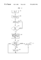
- FIG. 4 illustrates a flowchart describing the handshaking required between the handsets and the base station of FIG. 1 .
- FIGS. 1-4 A preferred embodiment of the present invention will now be described with reference to FIGS. 1-4.
- Other embodiments may be realized and structural, or logical changes may be made to and equivalents used for the disclosed embodiment without departing from the spirit or scope of the present invention.
- FIG. 1 depicts a typical multiple handset cordless telephone environment.
- the FIG. 1 environment consists of a subscriber telephone base station 10 plus a plurality of handsets, e.g. two handsets 20 , 22 , all of which are operating on the same subscriber telephone line 100 and within the same household. Communication between the base station 10 and the handsets 20 , 22 is achieved via wireless transmission of signals.
- each of the handsets 20 , 22 are off-hook and currently engaged in an open line communication with the base station 10 .
- Each handset 20 , 22 and the base station are depicted as being coupled together by an RF link 250 , 252 .
- each of the handsets 20 , 22 may independently communicate with each other as well as the base station 10 , as described in detail later herein.
- the present invention may employ a frequency division duplex system or a time division duplex system, such as that described in U.S. Pat. No. 5,809,417 (Nealon et al.) and incorporated herein by reference.
- a frequency division duplex system for example, each one of the handsets 20 , 22 is configured with a different starting channel from a plurality of communication channels available in a frequency hopping system.
- Frequency division duplexing is a multiplexing scheme in which the available transmission frequency range is divided into narrower bands. Each of these bands is used to carry a separate channel.
- the base station 10 For providing initial communications with the handsets 20 , 22 , the base station 10 transmits a broadcast signal sequentially over a set of communication channels while monitoring each one of the starting channels of each handset 20 , 22 .
- a user-initiated response from the handsets 20 , 22 receiving the broadcast signal from the base station 10 causes a response signal to be transmitted from the handsets 20 , 22 to the base station 10 over the respective starting channel of each handset 20 , 22 .
- the base station 10 and responding handset 20 , 22 then establish communications over a set of communication channels assigned to the respective responding handset 20 , 22 .
- FIG. 2 a block diagram of circuitry located within base station 10 is depicted. Included in the base station 10 are a control unit 110 , a router 114 , a clock 120 for providing synchronization to: 1) the control unit 110 , 2) a time domain duplexer (TDD) 124 and 3) the speech codec 116 and ADPCM module 118 . Also included in the base station 10 are a radio frequency (RF) transceiver 122 , a signal strength monitor circuit 130 , an antenna 102 and a frequency synthesizer 128 . A line interface 112 in the base station 10 connects this unit to a central office or other appropriate switch through tip and ring lines 100 and 101 .
- RF radio frequency
- An interface unit and display 126 contains the switches and a visual display for configuring the base station in its various modes for communicating with one or more of the handsets 20 , 22 .
- the transceiver 122 comprises both an RF transmitter and an RF receiver.
- the transceiver 122 demodulates voice signals transmitted by the handsets 20 , 22 and couples these signals via the router 114 , preferably an analog switch controlled by the controller 110 , and either the speech codec 116 or the ADPCM module 118 to the line interface 112 .
- the transceiver 122 also has as its input speech and other control signals from the line interface 112 which are first coupled through the router 114 and either the speech codec 116 or the ADPCM module 118 before being transmitted to the handsets 20 , 22 by the transceiver 122 .
- the line interface 112 serves as a “plain old telephone service” (POTS) interface for signals on the tip-ring lines 100 and 101 and for those signals received from the handsets 20 , 22 by the RF transceiver 122 .
- POTS plain old telephone service
- the controller 110 advantageously provides a number of control functions and may be implemented through the use of a microcomputer containing read-only-memory (ROM), random-access-memory (RAM) and through use of the proper coding.
- the controller 110 controls and configures the TDD 124 .
- the controller 110 generates a pseudo-random data list and transmits the list to the TDD 124 where it is stored therein.
- the TDD 124 controls the frequencies selected in the frequency hopping cycle of the base station 10 by inputting into the frequency synthesizer 128 at the appropriate time the values stored in the data list generated by the controller 110 .
- the TDD 124 also refreshes the frequency synthesizer 128 as the synthesizer progresses though the frequency hopping cycle.
- the signal strength monitor circuit 135 In order for the base station 10 to achieve effective coverage throughout its operating range, the signal strength monitor circuit 135 continually monitors the strength of the received signal from the handsets 20 , 22 during ongoing communications with the handsets 20 , 22 .
- This signal strength monitor circuit 135 may be, for example, a received signal strength indicator (RSSI) circuit.
- RSSI received signal strength indicator
- This RSSI circuit produces an output voltage that is proportional to the strength of the received signal from the handsets 20 , 22 .
- the controller 110 Responsive to the strength of the received signal from the handset 20 , as determined by the signal strength monitor circuit 135 , the controller 110 is capable of recalculating the amount of power transmitted by the transmitter in the RF transceiver 122 to the handsets 20 , 22 .
- the level of power radiated by the RF transceiver 122 is reduced to a minimum acceptable level.
- the level of power radiated by RF transceiver 122 can be increased to its maximum permitted level.
- the functions of the router 114 , speech codec 116 , and ADPCM module 118 are combined within a single digital signal processing (DSP) chip.
- DSP digital signal processing
- FIG. 3 depicts a block diagram of circuitry located within a handset 20 .
- a controller 158 a router 152 , a clock 160 for providing synchronization to: 1) the controller 158 , 2) a time domain duplexer (TDD) 162 and 3) the speech codec 154 and ADPCM module 156 .
- TDD time domain duplexer
- Also included in the handset 20 are an RF transceiver 150 , a signal strength monitor circuit 170 , an antenna 172 and a frequency synthesizer 168 .
- An interface unit and display 164 contains switches and a visual display for configuring the handset 20 in an appropriate mode for communicating with the base station 10 as well as permits dialing telephone digits and selecting such functions as talk, intercom and page modes for the handset 20 to communicate with the base station 10 .
- Handsets 20 and 22 contain the same components and are operationally identical.
- the transceiver 150 comprises both an RF transmitter and an RF receiver. This transceiver 150 demodulates voice signals transmitted by the base station 10 and couples these signals via the router 152 and either the speech codec 154 or ADPCM module 156 to a speaker 176 on line 252 .
- the transceiver 150 also has as its input digital speech signals which have been transmitted from a microphone 174 in analog form through router 152 , speech codec 154 or ADPCM module 156 , TDD 162 , and frequency synthesizer 168 . Either the ADPCM module 156 or speech codec 154 is used to convert the analog signal to a digital signal which is then provided to the RF transceiver 150 .
- the signal strength monitor 170 monitors the received signal level from the base station 10 and accordingly varies the level of the output power radiated by the 1 I transceiver 150 in proportion to this received signal level.
- the functions of the router 152 , speech codec 154 , and ADPCM module 156 are combined within a single digital signal processing (DSP) chip.
- DSP digital signal processing
- Each of the handsets 20 , 22 must be provided with a security code from the base station 10 during a registration process in order for subsequent radio frequency communications to take place between the base station 10 and a handset 20 , 22 or between handsets 20 , 22 .
- the control unit 158 enables the TDD 162 to establish synchronization with the RF signal being received from the base station 10 . This may be accomplished by tie base station 10 transmitting a unique identification code which must be registered by the individual handset 20 , 22 .
- the security code data is generated in the base station in accordance with the teachings of U.S. Pat. No. 4,736,404 (R. E. Anglikoivski et al.), incorporated herein by reference.
- the starting channel data is a pseudo-random number seed. This seed, used for generating the starting channel and also random subsequent channels, is generated by the control unit in the base station.
- the handset unit automatically acknowledges to the base station when it has received the security code data and the starting channel data. Once this data has been received and acknowledged, both the base station and the handset unit begin frequency hopping in the manner described in U.S. Pat. No. 5,353,341 (M. E. Gillis et al.), incorporated herein by reference.
- a third party calls a subscriber.
- the incoming telephone signal is received by the base station 10 in step S 302 and routed through the line interface 112 to the router 114 on line 200 .
- the controller 110 Upon detection of an incoming telephone signal, the controller 110 signals a user that an incoming call has been received in step S 304 . Such signaling may occur, for example, by the use of an audio alarm contained in the base station 10 or by a signal generated within the base and transmitted to the handsets 20 , 22 .
- the controller 110 monitors the input of router 114 received from RF transceiver 122 until an off-hook signal has been received from at least one handset 20 , 22 in step S 306 .
- Controller 110 controls the router 114 such that the incoming remote signal is routed through the ADPCM module 118 .
- the ADPCM module 118 encodes the incoming remote signal using ADPCM encoding techniques known in the art such as, for example, G.726 compliant ADPCM techniques.
- the encoded signal is routed through the TDD 124 , frequency synthesizer 128 , and RF transceiver 122 for RF transmission to the handsets 20 , 22 in step S 308 .
- a handset 20 , 22 Upon going off-hook through, for example, depression of a specified key by the user in step S 306 , a handset 20 , 22 generates an off-hook control signal which is transmitted to the base station 10 to be detected by the controller 110 . Dependant upon the number of off-hook handsets 20 , 22 the controller 11 has detected in step S 310 , being one or more than one, the controller 110 generates a control signal transmitted to the handsets 20 , 22 to encode outgoing signals using either the ADPCM module 118 in step S 314 or the speech codec 116 in step S 312 , respectively.
- the speech codec 116 is preferably circuitry designed to encode and decode speech on 4, 8 or 16 Kb/s digital channels through techniques such as, for example, waveform coding, linear coding (PCM), differential coding (DPCM), frequency-domain coding, or parametric coding (a vocoder such as format vocoder (synthesizer) or an LPC vocoder).
- the speech codecs 116 and 154 may be permanently configured to encode and decode speech based upon 4, 8 or 16 Kb/s digital channels or may be dynamically configurable to process on 4, 8, and 16 Kb/s channels the choice of which is determined by the number of off-hook handsets the controller 110 detects.
- any change in off-hook status will force the controller 110 to recalculate the current number of off-hook handsets 20 , 22 and send control signals to the handsets 20 , 22 instructing them to route the outgoing signals through either the speech codec 116 if more than handset 20 , 22 is off-hook or the ADPCM module 118 if only one handset 20 or 22 is off-hook.
- Multiple simultaneous signals received by the base station 10 from the handsets 20 share the speech codec 116 through a time division system controlled by the controller 110 and the router 114 .
- one speech codec unit 154 may be present for each handset 20 , 22 .
- the continuous monitoring of the off-hook status of the handsets 20 , 22 by the base station 10 in step S 310 continues until the telephone call has been terminated.
- the handsets 20 , 22 are capable of communication with each other through the use of control/identification signals such as those described in U.S. Pat. No. 5,809,417 (Nealon et al.) and incorporated herein by reference.
- outgoing communications signals are encoded using the speech codec 154 and may be accompanied by a control signal also generated by the speech codec 154 .
- the controller 158 Upon receipt of a speech coded RF signal, the controller 158 recognizes the signal as being speech coded through the use of tie accompanying control signal.
- the controller 158 routes the signals through router 152 to the speech codec 154 for decoding before transmission to the speaker 176 on line 252 .
- Incoming signals which are not accompanied by a control signal or have a control signal corresponding to ADPCM encoding are presumed to come from the base 10 and have been ADPCM encoded.
- the controller 158 routes such signals to the ADPCM module 156 .
- the handsets 20 , 22 communicate to one another through the base station 10 .
- An outgoing signal generated by handset 20 is speech coded by speech codec 154 and transmitted to base station 10 .
- Base station 10 may configured to either automatically rebroadcast the speech coded signal using the router 114 or to decode the incoming signal using speech codec 116 . If the signal is decoded, it must be encoded again, preferably using the ADPCM module 118 to preserve voice quality transmission. The signal is preferably immediately rebroadcast due to the signal loss experienced by double encoded signals.
- cordless telephone handsets 20 , 22 have been depicted in the multi-cordless environment for purposes of simplicity, any number of cordless telephone handsets 20 , 22 with a single base station 10 may be used in successfully practicing the invention.
- the invention may be successfully implemented within any cordless telephone environment employing an RF link between a handset and a base station. It should also be noted that the invention's usefulness is not limited to an RF link of any one specific frequency. Also, although the invention is described using frequency division duplexing techniques, other multiplexing techniques such as time division multiplexing can also be used.
- FIG. 2 and FIG. 3 block diagrams While specific circuitry has been depicted as being located within a base station, design modifications may be made such that the circuitry is located within a handset, and vice versa.
- the control signals are depicted as being generated within the base station 10 , alternatively, some of those signals may be generated within the handsets 20 , 22 . Accordingly, the invention is not limited by the foregoing description or drawings, but is only limited by the scope of the appended claims.
Abstract
Description
Claims (84)
Priority Applications (1)
| Application Number | Priority Date | Filing Date | Title |
|---|---|---|---|
| US09/332,514 US6349213B1 (en) | 1999-06-14 | 1999-06-14 | Apparatus for enhanced voice quality in multiple cordless handset environment and method |
Applications Claiming Priority (1)
| Application Number | Priority Date | Filing Date | Title |
|---|---|---|---|
| US09/332,514 US6349213B1 (en) | 1999-06-14 | 1999-06-14 | Apparatus for enhanced voice quality in multiple cordless handset environment and method |
Publications (1)
| Publication Number | Publication Date |
|---|---|
| US6349213B1 true US6349213B1 (en) | 2002-02-19 |
Family
ID=23298568
Family Applications (1)
| Application Number | Title | Priority Date | Filing Date |
|---|---|---|---|
| US09/332,514 Expired - Lifetime US6349213B1 (en) | 1999-06-14 | 1999-06-14 | Apparatus for enhanced voice quality in multiple cordless handset environment and method |
Country Status (1)
| Country | Link |
|---|---|
| US (1) | US6349213B1 (en) |
Cited By (7)
| Publication number | Priority date | Publication date | Assignee | Title |
|---|---|---|---|---|
| US20020105913A1 (en) * | 2000-06-16 | 2002-08-08 | Kazuyuki Miya | Communication terminal apparatus and radio communication method |
| US20020107036A1 (en) * | 2001-02-07 | 2002-08-08 | Cannon Joseph M. | Cordless telephone active-call enabled intercom |
| US6574486B1 (en) * | 2000-02-08 | 2003-06-03 | Qualcomm, Incorporated | Method and apparatus for selecting among calling options in a wireless communication device |
| WO2004045098A1 (en) * | 2002-11-08 | 2004-05-27 | Carl Underwood | Cellular phone cordless home base unit |
| US20070123251A1 (en) * | 1996-10-23 | 2007-05-31 | Riparius Ventures, Llc | Remote internet telephony device |
| EP2180678A2 (en) * | 2008-10-27 | 2010-04-28 | Gigaset Communications GmbH | Device and method for adjusting bandwidth in a telecommunications network and accompanying computer program product |
| US20110268276A1 (en) * | 2005-07-14 | 2011-11-03 | Tara Chand Singhal | Apparatus and method for communication security in a nationwide wireless network |
Citations (13)
| Publication number | Priority date | Publication date | Assignee | Title |
|---|---|---|---|---|
| US4747096A (en) | 1985-04-17 | 1988-05-24 | Eci Telecom Limited | Combination TASI and ADPCM apparatus |
| US5050601A (en) | 1990-05-29 | 1991-09-24 | Joel Kupersmith | Cardiac defibrillator electrode arrangement |
| US5228076A (en) | 1989-06-12 | 1993-07-13 | Emil Hopner | High fidelity speech encoding for telecommunications systems |
| US5297203A (en) | 1991-05-29 | 1994-03-22 | Video Technology Engineering, Ltd. | Digital cordless telephone apparatus |
| US5325420A (en) | 1992-09-30 | 1994-06-28 | Fujitsu Limited | Cordless phone haaving a plurality of personal stations |
| US5367570A (en) | 1993-06-25 | 1994-11-22 | Figueroa Hector D | Dual telephone |
| US5689549A (en) | 1994-12-01 | 1997-11-18 | Lucent Technologies Inc. | Cordless telephone base unit arranged for operating with multiple portable units |
| US5754642A (en) | 1993-09-01 | 1998-05-19 | Hitachi Telecom Technologies, Ltd. | Telephone terminal having multiple handsets |
| US5784456A (en) | 1995-06-29 | 1998-07-21 | Cyracom International, Inc. | Single-line multi-handset telephone |
| US5809417A (en) * | 1994-07-05 | 1998-09-15 | Lucent Technologies Inc. | Cordless telephone arranged for operating with multiple portable units in a frequency hopping system |
| US5855003A (en) * | 1996-10-11 | 1998-12-29 | Motorola, Inc. | Method and apparatus for establishing a link in a wireless communication system |
| US5991642A (en) * | 1995-01-10 | 1999-11-23 | Ntt Mobile Communications Network Inc. | Mobile communication system having a control station which selects speech coding schemes for a mobile station |
| US6188884B1 (en) * | 1997-03-11 | 2001-02-13 | U.S. Philips Corporation | Telephony device comprising a digital processing element for speech signals and method implemented in such a device |
-
1999
- 1999-06-14 US US09/332,514 patent/US6349213B1/en not_active Expired - Lifetime
Patent Citations (13)
| Publication number | Priority date | Publication date | Assignee | Title |
|---|---|---|---|---|
| US4747096A (en) | 1985-04-17 | 1988-05-24 | Eci Telecom Limited | Combination TASI and ADPCM apparatus |
| US5228076A (en) | 1989-06-12 | 1993-07-13 | Emil Hopner | High fidelity speech encoding for telecommunications systems |
| US5050601A (en) | 1990-05-29 | 1991-09-24 | Joel Kupersmith | Cardiac defibrillator electrode arrangement |
| US5297203A (en) | 1991-05-29 | 1994-03-22 | Video Technology Engineering, Ltd. | Digital cordless telephone apparatus |
| US5325420A (en) | 1992-09-30 | 1994-06-28 | Fujitsu Limited | Cordless phone haaving a plurality of personal stations |
| US5367570A (en) | 1993-06-25 | 1994-11-22 | Figueroa Hector D | Dual telephone |
| US5754642A (en) | 1993-09-01 | 1998-05-19 | Hitachi Telecom Technologies, Ltd. | Telephone terminal having multiple handsets |
| US5809417A (en) * | 1994-07-05 | 1998-09-15 | Lucent Technologies Inc. | Cordless telephone arranged for operating with multiple portable units in a frequency hopping system |
| US5689549A (en) | 1994-12-01 | 1997-11-18 | Lucent Technologies Inc. | Cordless telephone base unit arranged for operating with multiple portable units |
| US5991642A (en) * | 1995-01-10 | 1999-11-23 | Ntt Mobile Communications Network Inc. | Mobile communication system having a control station which selects speech coding schemes for a mobile station |
| US5784456A (en) | 1995-06-29 | 1998-07-21 | Cyracom International, Inc. | Single-line multi-handset telephone |
| US5855003A (en) * | 1996-10-11 | 1998-12-29 | Motorola, Inc. | Method and apparatus for establishing a link in a wireless communication system |
| US6188884B1 (en) * | 1997-03-11 | 2001-02-13 | U.S. Philips Corporation | Telephony device comprising a digital processing element for speech signals and method implemented in such a device |
Cited By (12)
| Publication number | Priority date | Publication date | Assignee | Title |
|---|---|---|---|---|
| US20070123251A1 (en) * | 1996-10-23 | 2007-05-31 | Riparius Ventures, Llc | Remote internet telephony device |
| US6574486B1 (en) * | 2000-02-08 | 2003-06-03 | Qualcomm, Incorporated | Method and apparatus for selecting among calling options in a wireless communication device |
| US20020105913A1 (en) * | 2000-06-16 | 2002-08-08 | Kazuyuki Miya | Communication terminal apparatus and radio communication method |
| US20020107036A1 (en) * | 2001-02-07 | 2002-08-08 | Cannon Joseph M. | Cordless telephone active-call enabled intercom |
| US8131308B2 (en) * | 2001-02-07 | 2012-03-06 | Agere Systems Inc. | Active-call intercom-enabled cordless telephone |
| US8423055B2 (en) | 2001-02-07 | 2013-04-16 | Agere Systems Llc | Cordless telephone active-call enabled intercom |
| US8688149B2 (en) | 2001-02-07 | 2014-04-01 | Agere Systems Llc | Cordless telephone active-call enabled intercom |
| WO2004045098A1 (en) * | 2002-11-08 | 2004-05-27 | Carl Underwood | Cellular phone cordless home base unit |
| US20110268276A1 (en) * | 2005-07-14 | 2011-11-03 | Tara Chand Singhal | Apparatus and method for communication security in a nationwide wireless network |
| US9686684B2 (en) * | 2005-07-14 | 2017-06-20 | Tara Chand Singhal | Apparatus and method for communication security in a nationwide wireless network |
| EP2180678A2 (en) * | 2008-10-27 | 2010-04-28 | Gigaset Communications GmbH | Device and method for adjusting bandwidth in a telecommunications network and accompanying computer program product |
| EP2180678A3 (en) * | 2008-10-27 | 2010-07-21 | Gigaset Communications GmbH | Device and method for adjusting bandwidth in a telecommunications network and accompanying computer program product |
Similar Documents
| Publication | Publication Date | Title |
|---|---|---|
| US6381472B1 (en) | TDD/TTY-digital access | |
| US5398258A (en) | Wireless communication system | |
| CA2147976C (en) | Radio link parameter control in wireless personal communications system | |
| US7221662B2 (en) | Tone detection elimination | |
| US4560832A (en) | Telephone system | |
| JPH0833040A (en) | Personal telephone extension system | |
| KR100547088B1 (en) | System and method for providing intercom and multiple voice channels in a private telephone system | |
| JPH08130775A (en) | Digital cordless telephone system | |
| US5384807A (en) | ADPCM transcoder with integral tone generation and method therefor | |
| US4682350A (en) | Equipment for wireless telephone transmission | |
| US7561873B2 (en) | Mobile handset as TTY device | |
| US6349213B1 (en) | Apparatus for enhanced voice quality in multiple cordless handset environment and method | |
| WO1997034433A1 (en) | A communication method and an adapter between a wireless telephone terminal and a data source | |
| JP3170161B2 (en) | Digital cordless telephone system and digital cordless telephone | |
| KR100240280B1 (en) | Data communication method using cordless telephone | |
| JP2684125B2 (en) | Audio processing device | |
| JP2002314680A (en) | Wired-radio telephone conversion device | |
| WO2005086431A1 (en) | Ip phone with dual mode bluetooth stack | |
| JPH066304A (en) | Cordless telephone set capable of dialing from external terminal equipment | |
| KR20010018915A (en) | Apparatus and method for transmitting user information byuse of dtmf in portable radio communication terminal | |
| JPH02162932A (en) | Transmitter-receiver | |
| JP2003309528A (en) | Wireless mobile communications system | |
| JP2001223635A (en) | Portable telephone system | |
| JPH05188985A (en) | Speech compression system, communication system, and radio communication device | |
| JPH08317077A (en) | Device for connecting portable telephone set to wired line |
Legal Events
| Date | Code | Title | Description |
|---|---|---|---|
| AS | Assignment |
Owner name: LUCENT TECHNOLOGIES, INC, NEW JERSEY Free format text: ASSIGNMENT OF ASSIGNORS INTEREST;ASSIGNORS:IYENGAR, VASU;UBOWSKI, RICHARD;REEL/FRAME:010031/0224 Effective date: 19990607 |
|
| STCF | Information on status: patent grant |
Free format text: PATENTED CASE |
|
| FPAY | Fee payment |
Year of fee payment: 4 |
|
| FPAY | Fee payment |
Year of fee payment: 8 |
|
| FPAY | Fee payment |
Year of fee payment: 12 |
|
| AS | Assignment |
Owner name: DEUTSCHE BANK AG NEW YORK BRANCH, AS COLLATERAL AG Free format text: PATENT SECURITY AGREEMENT;ASSIGNORS:LSI CORPORATION;AGERE SYSTEMS LLC;REEL/FRAME:032856/0031 Effective date: 20140506 |
|
| AS | Assignment |
Owner name: AVAGO TECHNOLOGIES GENERAL IP (SINGAPORE) PTE. LTD Free format text: ASSIGNMENT OF ASSIGNORS INTEREST;ASSIGNOR:AGERE SYSTEMS LLC;REEL/FRAME:035365/0634 Effective date: 20140804 |
|
| AS | Assignment |
Owner name: LSI CORPORATION, CALIFORNIA Free format text: TERMINATION AND RELEASE OF SECURITY INTEREST IN PATENT RIGHTS (RELEASES RF 032856-0031);ASSIGNOR:DEUTSCHE BANK AG NEW YORK BRANCH, AS COLLATERAL AGENT;REEL/FRAME:037684/0039 Effective date: 20160201 Owner name: AGERE SYSTEMS LLC, PENNSYLVANIA Free format text: TERMINATION AND RELEASE OF SECURITY INTEREST IN PATENT RIGHTS (RELEASES RF 032856-0031);ASSIGNOR:DEUTSCHE BANK AG NEW YORK BRANCH, AS COLLATERAL AGENT;REEL/FRAME:037684/0039 Effective date: 20160201 |
|
| AS | Assignment |
Owner name: BANK OF AMERICA, N.A., AS COLLATERAL AGENT, NORTH CAROLINA Free format text: PATENT SECURITY AGREEMENT;ASSIGNOR:AVAGO TECHNOLOGIES GENERAL IP (SINGAPORE) PTE. LTD.;REEL/FRAME:037808/0001 Effective date: 20160201 Owner name: BANK OF AMERICA, N.A., AS COLLATERAL AGENT, NORTH Free format text: PATENT SECURITY AGREEMENT;ASSIGNOR:AVAGO TECHNOLOGIES GENERAL IP (SINGAPORE) PTE. LTD.;REEL/FRAME:037808/0001 Effective date: 20160201 |
|
| AS | Assignment |
Owner name: AVAGO TECHNOLOGIES GENERAL IP (SINGAPORE) PTE. LTD., SINGAPORE Free format text: TERMINATION AND RELEASE OF SECURITY INTEREST IN PATENTS;ASSIGNOR:BANK OF AMERICA, N.A., AS COLLATERAL AGENT;REEL/FRAME:041710/0001 Effective date: 20170119 Owner name: AVAGO TECHNOLOGIES GENERAL IP (SINGAPORE) PTE. LTD Free format text: TERMINATION AND RELEASE OF SECURITY INTEREST IN PATENTS;ASSIGNOR:BANK OF AMERICA, N.A., AS COLLATERAL AGENT;REEL/FRAME:041710/0001 Effective date: 20170119 |
|
| AS | Assignment |
Owner name: AVAGO TECHNOLOGIES INTERNATIONAL SALES PTE. LIMITE Free format text: MERGER;ASSIGNOR:AVAGO TECHNOLOGIES GENERAL IP (SINGAPORE) PTE. LTD.;REEL/FRAME:047195/0026 Effective date: 20180509 |
|
| AS | Assignment |
Owner name: AVAGO TECHNOLOGIES INTERNATIONAL SALES PTE. LIMITE Free format text: CORRECTIVE ASSIGNMENT TO CORRECT THE EFFECTIVE DATE OF MERGER PREVIOUSLY RECORDED ON REEL 047195 FRAME 0026. ASSIGNOR(S) HEREBY CONFIRMS THE MERGER;ASSIGNOR:AVAGO TECHNOLOGIES GENERAL IP (SINGAPORE) PTE. LTD.;REEL/FRAME:047477/0423 Effective date: 20180905 |