US6357031B1 - Serial data transmission apparatus and method with a data checking feature - Google Patents
Serial data transmission apparatus and method with a data checking feature Download PDFInfo
- Publication number
- US6357031B1 US6357031B1 US09/021,939 US2193998A US6357031B1 US 6357031 B1 US6357031 B1 US 6357031B1 US 2193998 A US2193998 A US 2193998A US 6357031 B1 US6357031 B1 US 6357031B1
- Authority
- US
- United States
- Prior art keywords
- data
- checking
- detection
- source data
- generate
- Prior art date
- Legal status (The legal status is an assumption and is not a legal conclusion. Google has not performed a legal analysis and makes no representation as to the accuracy of the status listed.)
- Expired - Lifetime
Links
Images


Classifications
-
- H—ELECTRICITY
- H04—ELECTRIC COMMUNICATION TECHNIQUE
- H04L—TRANSMISSION OF DIGITAL INFORMATION, e.g. TELEGRAPHIC COMMUNICATION
- H04L1/00—Arrangements for detecting or preventing errors in the information received
-
- H—ELECTRICITY
- H04—ELECTRIC COMMUNICATION TECHNIQUE
- H04L—TRANSMISSION OF DIGITAL INFORMATION, e.g. TELEGRAPHIC COMMUNICATION
- H04L1/00—Arrangements for detecting or preventing errors in the information received
- H04L1/004—Arrangements for detecting or preventing errors in the information received by using forward error control
- H04L1/0056—Systems characterized by the type of code used
- H04L1/0061—Error detection codes
-
- G—PHYSICS
- G11—INFORMATION STORAGE
- G11B—INFORMATION STORAGE BASED ON RELATIVE MOVEMENT BETWEEN RECORD CARRIER AND TRANSDUCER
- G11B20/00—Signal processing not specific to the method of recording or reproducing; Circuits therefor
- G11B20/10—Digital recording or reproducing
- G11B20/18—Error detection or correction; Testing, e.g. of drop-outs
- G11B20/1833—Error detection or correction; Testing, e.g. of drop-outs by adding special lists or symbols to the coded information
-
- H—ELECTRICITY
- H04—ELECTRIC COMMUNICATION TECHNIQUE
- H04L—TRANSMISSION OF DIGITAL INFORMATION, e.g. TELEGRAPHIC COMMUNICATION
- H04L1/00—Arrangements for detecting or preventing errors in the information received
- H04L1/004—Arrangements for detecting or preventing errors in the information received by using forward error control
- H04L1/0041—Arrangements at the transmitter end
-
- H—ELECTRICITY
- H04—ELECTRIC COMMUNICATION TECHNIQUE
- H04L—TRANSMISSION OF DIGITAL INFORMATION, e.g. TELEGRAPHIC COMMUNICATION
- H04L1/00—Arrangements for detecting or preventing errors in the information received
- H04L1/004—Arrangements for detecting or preventing errors in the information received by using forward error control
- H04L1/0045—Arrangements at the receiver end
-
- H—ELECTRICITY
- H04—ELECTRIC COMMUNICATION TECHNIQUE
- H04L—TRANSMISSION OF DIGITAL INFORMATION, e.g. TELEGRAPHIC COMMUNICATION
- H04L25/00—Baseband systems
- H04L25/38—Synchronous or start-stop systems, e.g. for Baudot code
- H04L25/40—Transmitting circuits; Receiving circuits
- H04L25/49—Transmitting circuits; Receiving circuits using code conversion at the transmitter; using predistortion; using insertion of idle bits for obtaining a desired frequency spectrum; using three or more amplitude levels ; Baseband coding techniques specific to data transmission systems
- H04L25/4904—Transmitting circuits; Receiving circuits using code conversion at the transmitter; using predistortion; using insertion of idle bits for obtaining a desired frequency spectrum; using three or more amplitude levels ; Baseband coding techniques specific to data transmission systems using self-synchronising codes, e.g. split-phase codes
-
- H—ELECTRICITY
- H04—ELECTRIC COMMUNICATION TECHNIQUE
- H04L—TRANSMISSION OF DIGITAL INFORMATION, e.g. TELEGRAPHIC COMMUNICATION
- H04L1/00—Arrangements for detecting or preventing errors in the information received
- H04L1/12—Arrangements for detecting or preventing errors in the information received by using return channel
- H04L1/16—Arrangements for detecting or preventing errors in the information received by using return channel in which the return channel carries supervisory signals, e.g. repetition request signals
- H04L1/18—Automatic repetition systems, e.g. Van Duuren systems
Definitions
- the present invention relates to a serial data transmission apparatus, and more particularly, to an improved serial data transmission apparatus which is capable of enhancing operational speed and is well adapted for serial data transmission using a cyclic redundancy checking (CRC) method.
- CRC cyclic redundancy checking
- the present invention is suitable for a wide scope of applications, it is particularly suitable for serially transmitting a large amount of data.
- the present invention also relates to a corresponding method for serially transmitting data.
- FIG. 1 illustrates a conventional serial data transmission apparatus.
- the conventional serial data transmission apparatus includes a transceiver 10 and a receiver 20 .
- the transceiver 10 includes a data storing unit 11 for storing source data to be transmitted and a data checking unit 12 for checking the data from the data storing unit 11 based on a cyclic redundancy checking (CRC) method.
- the transceiver 10 also includes a data combining unit 13 for combining the outputs from the data storing unit 11 and the data checking unit 12 to generate new data.
- the transceiver 10 further includes a data encoding unit 14 for encoding the data output from the data combining unit 13 using a non-return-zero-inverted (NRZI) method and serially transmitting the encoded data via a channel.
- NRZI non-return-zero-inverted
- the receiver 20 includes a data decoding unit 21 for receiving and decoding the NRZI type data transmitted from the transceiver 10 and a data separation unit 22 for separating the data from the data decoding unit 21 to restore it to the form before the data combination by the transceiver 10 . Also, the receiver 20 includes a data storing unit 23 for temporarily storing the source data separated by the data separation unit 22 , a data checking unit 24 for checking the output from the data storing unit 23 based on the CRC method, and a data comparison unit 25 for comparing the data in order to judge whether the output from the data checking unit 24 and the detection data separated by the data separation unit 22 are identical.
- the data storing unit 11 of the transceiver 10 outputs source data D 1 to the data checking unit 12 .
- the data checking unit 12 checks the data D 1 based on the CRC method and outputs the detection data d 1 .
- the data combining unit 13 combines the data D 1 from the data storing unit 11 and the detection data d 1 from the data checking unit 12 , and generates a new data (D 1 +d 1 ).
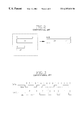
- the data (D 1 +d 1 ) is not to be confused as a mathematical sum of the data D 1 and d 1 . Instead, the data (D 1 +d 1 ) is generated by combining the bits of the data D 1 and d 1 , i.e., attaching the data d 1 to the end of the data D 1 as shown in FIG. 2 .
- the data combining unit 13 changes the data D 1 and d 1 having different lengths A and B, respectively, into a new (A+B)-bit data (D 1 +d 1 ).
- the data encoding unit 14 encodes the data (D 1 +d 1 ) by the non-return-to-zero-inverted (NRZI) method.
- the encoded data (D 1 +d 1 )′ is transmitted to the receiver 20 .
- the non-return-to-zero-inverted (NRZI) method is a data encoding method for changing the magnetized state of the encoded data only at falling edges, i.e., when the source data changes the state from 1 to 0, thus generating a different type of data.
- the method may also be set to change the magnetized state of the encoded data only at rising edges.
- the data decoding unit 21 of the receiver 20 decodes the transmitted data (D 1 +d 1 )′ to restore the original form of the data (D 1 +d 1 ) and outputs the data to the data separation unit 22 .
- the data separation unit 22 separates the data (D 1 +d 1 ) into the source data D 1 and the detection data d 1 , and outputs the separated data D 1 and d 1 .
- the source data D 1 separated by the data separation unit 22 is transmitted to the data checking unit 24 through the data storing unit 23 .
- the data checking unit 24 checks the source data D 1 based on the CRC method and outputs a different detection data d 1 ′.
- the data comparison unit 25 decides whether the detection data d 1 ′ output by the data checking unit 25 and the restored detection data d 1 separated by the data separation unit 22 are identical.
- the data comparison unit 25 outputs a first signal.
- the transceiver 10 transmits the next data D 2 to the receiver 20 , and the source data D 1 is outputted from the data storing unit 23 .
- the first bit signal has a value of 0 or 1.
- the data comparison unit 25 outputs a second bit signal. In response to the second bit signal, the transceiver 10 does not transmit the next data D 2 to the receiver 2 , and the previously transmitted source data D 1 is transmitted again.
- the conventional serial data transmission apparatus only after the decoding, data separation, cyclic redundancy checking, and comparison processes are sequentially performed to determine that the data transmitted from the transceiver to the receiver is correct, the transceiver can transmit the next data to the receiver.
- the conventional serial data transmission apparatus has an inherent problem of lengthy transmission delay.
- the present invention is directed to a serial data transmission apparatus that substantially obviates one or more of the problems due to limitations and disadvantages of the related art.
- Another object of the present invention is to provide an improved serial data transmission apparatus which is capable of rapidly transmitting a large amount of data at a high speed by configuring a transceiver to have a function of performing an encoding operation before a cyclic redundancy checking operation is performed and by configuring a receiver to have a function of concurrently performing a decoding operation and a cyclic redundancy checking operation.
- a serial data transmission apparatus which includes a transceiver for encoding source data D 1 to be transmitted, performing a cyclic redundancy checking (CRC) operation on the encoded data D 1 ′, combining a detection data d 1 generated by a cyclic redundancy checking (CRC) operation and the encoded data D 1 ′ generated by the encoding, and outputting a combined data (D 1 ′+d 1 ); and a receiver for separating the combined data (D 1 ′+d 1 ) received from the transceiver into the data D 1 ′ and d 1 which are in formats before the data D 1 ′ and d 1 were combined by the transceiver, concurrently performing a decoding operation of the separated data D 1 ′ and a cyclic redundancy checking operation of the separated data D 1 ′, comparing the separated data d 1 with a detection data d 1 ′ generated
- CRC cyclic redundancy checking
- a serial data transmission apparatus which includes a transceiver for transmitting a source data, said transceiver having storing means for storing said source data, encoding means for encoding said source data, first checking means for checking the encoded source data to generate a first detection data, and combining means for combining said first detection data generated by said means for checking and said encoded source data to output a combined data; and a receiver for receiving said combined data.
- a method in a serial data transmission system having a transceiver with a storage means for storing a source data and a receiver, for serially transmitting said source data from said transceiver to said receiver comprising steps of encoding said source data, checking said encoded source data to generate a first detection data, combining said first detection data and said encoded source data to generate a combined data, and receiving said combined data.
- FIG. 1 is a block diagram illustrating a conventional serial data transmission apparatus
- FIG. 2 is a diagram illustrating the operation of a data summation unit in the apparatus of FIG. 1;
- FIG. 3 is a diagram illustrating data which is encoded by using a non-return-to-zero-inverted method in the apparatus of FIG. 1;
- FIG. 4 is a block diagram illustrating a serial data transmission apparatus according to the present invention.
- a serial data transmission apparatus includes a transceiver 30 for transmitting data and a receiver 40 for receiving and processing the data.
- the transceiver 30 is configured to perform an encoding operation before a cyclic redundancy checking operation is performed with respect to source data.
- the transceiver 30 is also configured to combine a detection data d 1 generated from the cyclic redundancy checking operation and a data D 1 ′ which is generated by performing the encoding operation on the source data D 1 .
- the combined data is defined as (D 1 ′+d 1 ) which is formed by attaching the data d 1 to the end of the data D 1 ′.
- the receiver 40 is configured to separate the data (D 1 ′+d 1 ) received from the transceiver 30 into data having the same format as before the data was combined by the transceiver 30 .
- the receiver 40 is configured to concurrently perform a decoding operation on the separated data D 1 ′ to restore it into its original form D 1 and a cyclic redundancy checking operation.
- the receiver 40 is configured to compare the separated data d 1 with the detection data d 1 ′ generated from the cyclic redundancy checking operation and to judge whether the received data is correct based on the comparison.
- the data storing unit 31 of the transceiver 30 outputs the source data D 1 to the data encoding unit 32 .
- the data encoding unit 32 encodes the data D 1 by a non-return-to-zero-inverted (NRZI) method and outputs the encoded data D 1 ′ to the data checking unit 33 and a data combining unit 34 , respectively.
- the data checking unit 33 checks the data D 1 ′ based on the cyclic redundancy checking (CRC) method and outputs the detection data d 1 .
- CRC cyclic redundancy checking
- the data combining unit 34 combines the detection data d 1 from the data checking unit 33 and the data D 1 ′ from the data encoding unit 32 and generates the data (D 1 ′+d 1 ).
- the data (D 1 ′+d 1 ) is not to be confused as a mathematical sum of the data D 1 ′ and d 1 . Instead, the data (D 1 ′+d 1 ) is generated by combining the bits of the data D 1 ′ and d 1 , i.e., attaching the data d 1 to the end of the data D 1 ′. Then, the data combining unit 34 transmits the data (D 1 ′+d 1 ) to the receiver 40 via a channel.
- the data separation unit 41 of the receiver 40 receives the data (D 1 ′+d 1 ) from the data combining unit 34 of the transceiver and separates it into the data D 1 ′ and d 1 , the formats before the data are combined by the data combining unit 34 of the transceiver 30 .
- the decoding unit 42 decodes the data D 1 ′ separated by the data separation unit 41 and outputs the restored source data D 1 .
- the data checking unit 43 checks the data D 1 ′ based on the cyclic redundancy checking (CRC) method and outputs the detection data d 1 ′.
- CRC cyclic redundancy checking
- the data comparison unit 44 compares the detection data d 1 ′ from the data detection unit 43 with the detection data d 1 from the data separation unit 41 . If d 1 ′ is identical to d 1 , the data D 1 decoded by the decoding unit 42 is judged to be correct, and the data comparison unit 44 outputs an acknowledge signal (ACK) to the transceiver. In response to the acknowledge signal, the transceiver 30 transmits the next data to the receiver 40 .
- ACK acknowledge signal
- d 1 ′ is not identical to d 1 , the data D 1 is judged to be incorrect, and the data comparison unit 44 outputs an error signal (NAK) to the transceiver. In response to the NAK signal, transceiver 30 transmits the data D 1 again instead of transmitting the next data.
- NAK error signal
- the serial data transmission apparatus includes a transceiver capable of encoding data before a cyclic redundancy checking operation is performed, and a receiver capable of concurrently performing the decoding operation and the cyclic redundancy checking operation after separating the data received from the transceiver. Since the serial data transmission apparatus according to the present invention is capable of performing some operations concurrently, the operational speed of the serial data transmission apparatus is significantly enhanced. Also, because of the enhanced operational speed, the serial data transmission apparatus according to the present invention is much better suited for serial transmission of a large amount of data than the conventional art.
Abstract
Description
Claims (21)
Applications Claiming Priority (2)
| Application Number | Priority Date | Filing Date | Title |
|---|---|---|---|
| KR97/4407 | 1997-02-14 | ||
| KR1019970004407A KR100234026B1 (en) | 1997-02-14 | 1997-02-14 | Dc data transfer unit |
Publications (1)
| Publication Number | Publication Date |
|---|---|
| US6357031B1 true US6357031B1 (en) | 2002-03-12 |
Family
ID=19497002
Family Applications (1)
| Application Number | Title | Priority Date | Filing Date |
|---|---|---|---|
| US09/021,939 Expired - Lifetime US6357031B1 (en) | 1997-02-14 | 1998-02-11 | Serial data transmission apparatus and method with a data checking feature |
Country Status (4)
| Country | Link |
|---|---|
| US (1) | US6357031B1 (en) |
| JP (1) | JP2852922B2 (en) |
| KR (1) | KR100234026B1 (en) |
| TW (1) | TW349297B (en) |
Cited By (3)
| Publication number | Priority date | Publication date | Assignee | Title |
|---|---|---|---|---|
| US6760010B1 (en) * | 2000-03-15 | 2004-07-06 | Figaro Systems, Inc. | Wireless electronic libretto display apparatus and method |
| CN103546240A (en) * | 2013-09-24 | 2014-01-29 | 许继集团有限公司 | Ethernet CRC (cyclic redundancy check) checking method |
| US10142060B2 (en) * | 2017-04-01 | 2018-11-27 | Qualcomm Incorporated | Communication system and method having polar coding with two concatenated cyclic redundancy check codes |
Families Citing this family (3)
| Publication number | Priority date | Publication date | Assignee | Title |
|---|---|---|---|---|
| US5838267A (en) * | 1996-10-09 | 1998-11-17 | Ericsson, Inc. | Method and apparatus for encoding and decoding digital information |
| KR100555450B1 (en) * | 1998-06-30 | 2006-04-21 | 삼성전자주식회사 | High speed serial data decoder and decoding method thereof |
| CA2467429C (en) | 2001-11-15 | 2010-08-17 | Riken Keiki Co., Ltd. | Gas sensor |
Citations (12)
| Publication number | Priority date | Publication date | Assignee | Title |
|---|---|---|---|---|
| US5097507A (en) * | 1989-12-22 | 1992-03-17 | General Electric Company | Fading bit error protection for digital cellular multi-pulse speech coder |
| US5349589A (en) * | 1991-07-01 | 1994-09-20 | Ericsson Ge Mobile Communications Inc. | Generalized viterbi algorithm with tail-biting |
| US5434847A (en) * | 1993-02-26 | 1995-07-18 | Nec Corporation | Random access satellite communication system using random numbers generated in a range variable with channel traffic |
| US5519603A (en) * | 1992-06-12 | 1996-05-21 | The Dow Chemical Company | Intelligent process control communication system and method having capability to time align corresponding data sets |
| US5694428A (en) * | 1992-03-12 | 1997-12-02 | Ntp Incorporated | Transmitting circuitry for serial transmission of encoded information |
| WO1998038764A1 (en) * | 1997-02-27 | 1998-09-03 | Siemens Aktiengesellschaft | Frame-error detection method and device for error masking, specially in gsm transmissions |
| US5859859A (en) * | 1995-10-31 | 1999-01-12 | Samsung Electronics Co., Ltd. | Parallel cyclic redundancy code error detection |
| US5875202A (en) * | 1996-03-29 | 1999-02-23 | Adtran, Inc. | Transmission of encoded data over reliable digital communication link using enhanced error recovery mechanism |
| US5917837A (en) * | 1996-09-11 | 1999-06-29 | Qualcomm, Incorporated | Method and apparatus for performing decoding of codes with the use of side information associated with the encoded data |
| US5923679A (en) * | 1995-10-17 | 1999-07-13 | Oki Electric Industry Co., Ltd. | Error correction encoder, error correction decoder, and communication system |
| US6011817A (en) * | 1996-07-04 | 2000-01-04 | U.S. Philips Corporation | Transmission system and receiver with improved detection, and improved detection method |
| US6163873A (en) * | 1996-12-27 | 2000-12-19 | Kabushiki Kaisha Toshiba | Data communication method and system |
-
1997
- 1997-02-14 KR KR1019970004407A patent/KR100234026B1/en not_active IP Right Cessation
- 1997-10-20 TW TW086115441A patent/TW349297B/en active
-
1998
- 1998-02-09 JP JP10027189A patent/JP2852922B2/en not_active Expired - Fee Related
- 1998-02-11 US US09/021,939 patent/US6357031B1/en not_active Expired - Lifetime
Patent Citations (13)
| Publication number | Priority date | Publication date | Assignee | Title |
|---|---|---|---|---|
| US5097507A (en) * | 1989-12-22 | 1992-03-17 | General Electric Company | Fading bit error protection for digital cellular multi-pulse speech coder |
| US5349589A (en) * | 1991-07-01 | 1994-09-20 | Ericsson Ge Mobile Communications Inc. | Generalized viterbi algorithm with tail-biting |
| US5694428A (en) * | 1992-03-12 | 1997-12-02 | Ntp Incorporated | Transmitting circuitry for serial transmission of encoded information |
| US5519603A (en) * | 1992-06-12 | 1996-05-21 | The Dow Chemical Company | Intelligent process control communication system and method having capability to time align corresponding data sets |
| US5434847A (en) * | 1993-02-26 | 1995-07-18 | Nec Corporation | Random access satellite communication system using random numbers generated in a range variable with channel traffic |
| US5923679A (en) * | 1995-10-17 | 1999-07-13 | Oki Electric Industry Co., Ltd. | Error correction encoder, error correction decoder, and communication system |
| US5859859A (en) * | 1995-10-31 | 1999-01-12 | Samsung Electronics Co., Ltd. | Parallel cyclic redundancy code error detection |
| US5875202A (en) * | 1996-03-29 | 1999-02-23 | Adtran, Inc. | Transmission of encoded data over reliable digital communication link using enhanced error recovery mechanism |
| US6011817A (en) * | 1996-07-04 | 2000-01-04 | U.S. Philips Corporation | Transmission system and receiver with improved detection, and improved detection method |
| US5917837A (en) * | 1996-09-11 | 1999-06-29 | Qualcomm, Incorporated | Method and apparatus for performing decoding of codes with the use of side information associated with the encoded data |
| US6163873A (en) * | 1996-12-27 | 2000-12-19 | Kabushiki Kaisha Toshiba | Data communication method and system |
| WO1998038764A1 (en) * | 1997-02-27 | 1998-09-03 | Siemens Aktiengesellschaft | Frame-error detection method and device for error masking, specially in gsm transmissions |
| US6233708B1 (en) | 1997-02-27 | 2001-05-15 | Siemens Aktiengesellschaft | Method and device for frame error detection |
Non-Patent Citations (3)
| Title |
|---|
| "Universal Serial Bus" Specification, Version 1.0, Jan. 19, 1996, pp. 2, 147-151. |
| Rice, Comparative analysis of two realizations for hybird-ARQ error control, IEEE, p. 115-119, 1994.* |
| Souissi et al., A diversity combining DS/CDMA system with convolutional encoding and Viterbi decoding, IEEE, p. 304-312.* |
Cited By (3)
| Publication number | Priority date | Publication date | Assignee | Title |
|---|---|---|---|---|
| US6760010B1 (en) * | 2000-03-15 | 2004-07-06 | Figaro Systems, Inc. | Wireless electronic libretto display apparatus and method |
| CN103546240A (en) * | 2013-09-24 | 2014-01-29 | 许继集团有限公司 | Ethernet CRC (cyclic redundancy check) checking method |
| US10142060B2 (en) * | 2017-04-01 | 2018-11-27 | Qualcomm Incorporated | Communication system and method having polar coding with two concatenated cyclic redundancy check codes |
Also Published As
| Publication number | Publication date |
|---|---|
| KR19980068002A (en) | 1998-10-15 |
| JPH10233763A (en) | 1998-09-02 |
| TW349297B (en) | 1999-01-01 |
| JP2852922B2 (en) | 1999-02-03 |
| KR100234026B1 (en) | 1999-12-15 |
Similar Documents
| Publication | Publication Date | Title |
|---|---|---|
| US5923679A (en) | Error correction encoder, error correction decoder, and communication system | |
| US5953378A (en) | Frame synchronization circuit and communications system | |
| US4271520A (en) | Synchronizing technique for an error correcting digital transmission system | |
| US6725412B1 (en) | Low latency data encoder | |
| US5724391A (en) | Apparatus for transmission of variable length data | |
| US3646518A (en) | Feedback error control system | |
| US20080320375A1 (en) | Data transmitting apparatus and data receiving apparatus | |
| JP2000516415A (en) | Decoder using soft information output to minimize error rate | |
| US6163873A (en) | Data communication method and system | |
| JPH0412658B2 (en) | ||
| JP2003229838A (en) | Decoding method, decoding device and digital transmission system | |
| WO2003017501A9 (en) | System and method for encoding and decoding data utilizing modified reed-solomon codes | |
| US6357031B1 (en) | Serial data transmission apparatus and method with a data checking feature | |
| CN113507289B (en) | Encoder, decoder and code word generation method | |
| US20030051204A1 (en) | Interconnect system with error correction | |
| US5341384A (en) | Error detection method using CRC | |
| EP1300976A1 (en) | Method of blind transport format detection | |
| US5878061A (en) | Providing serial data clock signal transitions with parity bits | |
| US6226768B1 (en) | Coded frame synchronizing method and circuit | |
| JP2005012452A (en) | Device, method, and program for receiving digital signal | |
| US20050257117A1 (en) | Method and circuit for determining an ending of an ethernet frame | |
| KR20230050256A (en) | Data encoding method, encoder, and data decoding method | |
| US5544179A (en) | Mis-synchronization detection system using a combined error correcting and cycle identifier code | |
| US6007238A (en) | Communication method and communication system using the same | |
| US6408037B1 (en) | High-speed data decoding scheme for digital communication systems |
Legal Events
| Date | Code | Title | Description |
|---|---|---|---|
| AS | Assignment |
Owner name: LG SEMICON CO., LTD., KOREA, REPUBLIC OF Free format text: ASSIGNMENT OF ASSIGNORS INTEREST;ASSIGNOR:LEE, DAE-HUN;REEL/FRAME:008982/0235 Effective date: 19980125 |
|
| AS | Assignment |
Owner name: HYUNDAI ELECTRONICS INDUSTRIES, CO., LTD., KOREA, Free format text: MERGER;ASSIGNOR:LG SEMICON CO., LTD.;REEL/FRAME:010951/0606 Effective date: 19991020 |
|
| FEPP | Fee payment procedure |
Free format text: PAYOR NUMBER ASSIGNED (ORIGINAL EVENT CODE: ASPN); ENTITY STATUS OF PATENT OWNER: LARGE ENTITY |
|
| STCF | Information on status: patent grant |
Free format text: PATENTED CASE |
|
| AS | Assignment |
Owner name: HYNIX SEMICONDUCTOR INC., KOREA, REPUBLIC OF Free format text: CHANGE OF NAME;ASSIGNOR:HYUNDAI ELECTRONICS INDUSTRIES CO., LTD.;REEL/FRAME:015242/0899 Effective date: 20010329 |
|
| AS | Assignment |
Owner name: MAGNACHIP SEMICONDUCTOR, LTD., KOREA, REPUBLIC OF Free format text: ASSIGNMENT OF ASSIGNORS INTEREST;ASSIGNOR:HYNIX SEMICONDUCTOR, INC.;REEL/FRAME:016216/0649 Effective date: 20041004 |
|
| AS | Assignment |
Owner name: U.S. BANK NATIONAL ASSOCIATION, AS COLLATERAL TRUS Free format text: SECURITY INTEREST;ASSIGNOR:MAGNACHIP SEMICONDUCTOR, LTD.;REEL/FRAME:016470/0530 Effective date: 20041223 |
|
| FPAY | Fee payment |
Year of fee payment: 4 |
|
| AS | Assignment |
Owner name: HYUNDAI MICROELECTRONICS CO., LTD., KOREA, REPUBLI Free format text: CORRECTIVE ASSIGNMENT TO CORRECT THE CONVEYANCE TYPE, RECEIVING PARTY AND EXECUTION DATE PREVIOUSLY RECORDED ON REEL 010951 FRAME 0606;ASSIGNOR:LG SEMICON CO., LTD.;REEL/FRAME:022708/0564 Effective date: 19990726 |
|
| AS | Assignment |
Owner name: HYUNDAI ELECTRONICS INDUSTRIES CO., LTD., GEORGIA Free format text: MERGER;ASSIGNOR:HYUNDAI MICRO ELECTRONICS CO., LTD.;REEL/FRAME:022742/0478 Effective date: 19991014 |
|
| AS | Assignment |
Owner name: HYUNDAI ELECTRONICS INDUSTRIES CO., LTD., KOREA, R Free format text: CORRECTIVE ASSIGNMENT TO CORRECT THE COUNTRY IN THE ADDRESS OF THE RECEIVING PARTY PREVIOUSLY RECORDED ON REEL 022742 FRAME 0478;ASSIGNOR:HYUNDAI MICRO ELECTRONICS CO., LTD.;REEL/FRAME:022746/0279 Effective date: 19991014 |
|
| AS | Assignment |
Owner name: MAGNACHIP SEMICONDUCTOR, LTD., KOREA, REPUBLIC OF Free format text: PARTIAL RELEASE OF SECURITY INTEREST;ASSIGNOR:U.S. BANK NATIONAL ASSOCIATION, AS COLLATERAL TRUSTEE;REEL/FRAME:022746/0870 Effective date: 20090527 Owner name: CROSSTEK CAPITAL, LLC, DELAWARE Free format text: ASSIGNMENT OF ASSIGNORS INTEREST;ASSIGNOR:MAGNACHIP SEMICONDUCTOR, LTD.;REEL/FRAME:022764/0270 Effective date: 20090514 Owner name: CROSSTEK CAPITAL, LLC,DELAWARE Free format text: ASSIGNMENT OF ASSIGNORS INTEREST;ASSIGNOR:MAGNACHIP SEMICONDUCTOR, LTD.;REEL/FRAME:022764/0270 Effective date: 20090514 |
|
| AS | Assignment |
Owner name: YAT-SEN HOLDINGS, LLC, DELAWARE Free format text: ASSIGNMENT OF ASSIGNORS INTEREST;ASSIGNOR:CROSSTEK CAPITAL, LLC;REEL/FRAME:023094/0034 Effective date: 20090812 |
|
| FPAY | Fee payment |
Year of fee payment: 8 |
|
| FEPP | Fee payment procedure |
Free format text: PAYOR NUMBER ASSIGNED (ORIGINAL EVENT CODE: ASPN); ENTITY STATUS OF PATENT OWNER: LARGE ENTITY Free format text: PAYER NUMBER DE-ASSIGNED (ORIGINAL EVENT CODE: RMPN); ENTITY STATUS OF PATENT OWNER: LARGE ENTITY |
|
| AS | Assignment |
Owner name: INTELLECTUAL VENTURES II LLC, DELAWARE Free format text: MERGER;ASSIGNOR:YAT-SEN HOLDINGS, LLC;REEL/FRAME:025467/0090 Effective date: 20101207 |
|
| FPAY | Fee payment |
Year of fee payment: 12 |
|
| AS | Assignment |
Owner name: HANGER SOLUTIONS, LLC, GEORGIA Free format text: ASSIGNMENT OF ASSIGNORS INTEREST;ASSIGNOR:INTELLECTUAL VENTURES ASSETS 158 LLC;REEL/FRAME:051486/0425 Effective date: 20191206 |
|
| AS | Assignment |
Owner name: INTELLECTUAL VENTURES ASSETS 158 LLC, DELAWARE Free format text: ASSIGNMENT OF ASSIGNORS INTEREST;ASSIGNOR:INTELLECTUAL VENTURES II LLC;REEL/FRAME:051777/0107 Effective date: 20191126 |