US6483632B1 - Multistage optical amplifier with gain flattening - Google Patents
Multistage optical amplifier with gain flattening Download PDFInfo
- Publication number
- US6483632B1 US6483632B1 US09/214,248 US21424899A US6483632B1 US 6483632 B1 US6483632 B1 US 6483632B1 US 21424899 A US21424899 A US 21424899A US 6483632 B1 US6483632 B1 US 6483632B1
- Authority
- US
- United States
- Prior art keywords
- gain
- optical
- amplifier module
- amplifier
- concatenation
- Prior art date
- Legal status (The legal status is an assumption and is not a legal conclusion. Google has not performed a legal analysis and makes no representation as to the accuracy of the status listed.)
- Expired - Lifetime
Links
- 230000003287 optical effect Effects 0.000 title claims abstract description 100
- 238000001228 spectrum Methods 0.000 claims abstract description 35
- 229910052761 rare earth metal Inorganic materials 0.000 claims abstract description 9
- 150000002910 rare earth metals Chemical class 0.000 claims abstract description 9
- 230000001105 regulatory effect Effects 0.000 claims abstract description 8
- 230000005540 biological transmission Effects 0.000 claims description 25
- 230000033228 biological regulation Effects 0.000 claims description 16
- 230000003595 spectral effect Effects 0.000 claims description 14
- 238000000638 solvent extraction Methods 0.000 claims description 9
- 238000000034 method Methods 0.000 claims description 8
- 230000003321 amplification Effects 0.000 claims description 4
- 238000003199 nucleic acid amplification method Methods 0.000 claims description 4
- 230000009123 feedback regulation Effects 0.000 claims description 3
- 229910052691 Erbium Inorganic materials 0.000 claims description 2
- UYAHIZSMUZPPFV-UHFFFAOYSA-N erbium Chemical compound [Er] UYAHIZSMUZPPFV-UHFFFAOYSA-N 0.000 claims description 2
- 230000001747 exhibiting effect Effects 0.000 claims 1
- 238000010586 diagram Methods 0.000 description 6
- 230000000295 complement effect Effects 0.000 description 3
- 230000010355 oscillation Effects 0.000 description 3
- 238000011144 upstream manufacturing Methods 0.000 description 3
- 230000015556 catabolic process Effects 0.000 description 2
- 238000006731 degradation reaction Methods 0.000 description 2
- 230000000694 effects Effects 0.000 description 2
- 238000001914 filtration Methods 0.000 description 2
- 239000013307 optical fiber Substances 0.000 description 2
- 238000002310 reflectometry Methods 0.000 description 2
- 238000004458 analytical method Methods 0.000 description 1
- 230000003247 decreasing effect Effects 0.000 description 1
- 230000007935 neutral effect Effects 0.000 description 1
- 230000003019 stabilising effect Effects 0.000 description 1
Images


Classifications
-
- H—ELECTRICITY
- H04—ELECTRIC COMMUNICATION TECHNIQUE
- H04B—TRANSMISSION
- H04B10/00—Transmission systems employing electromagnetic waves other than radio-waves, e.g. infrared, visible or ultraviolet light, or employing corpuscular radiation, e.g. quantum communication
- H04B10/29—Repeaters
- H04B10/291—Repeaters in which processing or amplification is carried out without conversion of the main signal from optical form
- H04B10/2912—Repeaters in which processing or amplification is carried out without conversion of the main signal from optical form characterised by the medium used for amplification or processing
-
- H—ELECTRICITY
- H01—ELECTRIC ELEMENTS
- H01S—DEVICES USING THE PROCESS OF LIGHT AMPLIFICATION BY STIMULATED EMISSION OF RADIATION [LASER] TO AMPLIFY OR GENERATE LIGHT; DEVICES USING STIMULATED EMISSION OF ELECTROMAGNETIC RADIATION IN WAVE RANGES OTHER THAN OPTICAL
- H01S3/00—Lasers, i.e. devices using stimulated emission of electromagnetic radiation in the infrared, visible or ultraviolet wave range
- H01S3/10—Controlling the intensity, frequency, phase, polarisation or direction of the emitted radiation, e.g. switching, gating, modulating or demodulating
- H01S3/10007—Controlling the intensity, frequency, phase, polarisation or direction of the emitted radiation, e.g. switching, gating, modulating or demodulating in optical amplifiers
- H01S3/10023—Controlling the intensity, frequency, phase, polarisation or direction of the emitted radiation, e.g. switching, gating, modulating or demodulating in optical amplifiers by functional association of additional optical elements, e.g. filters, gratings, reflectors
-
- H—ELECTRICITY
- H04—ELECTRIC COMMUNICATION TECHNIQUE
- H04B—TRANSMISSION
- H04B10/00—Transmission systems employing electromagnetic waves other than radio-waves, e.g. infrared, visible or ultraviolet light, or employing corpuscular radiation, e.g. quantum communication
- H04B10/29—Repeaters
- H04B10/291—Repeaters in which processing or amplification is carried out without conversion of the main signal from optical form
- H04B10/293—Signal power control
- H04B10/294—Signal power control in a multiwavelength system, e.g. gain equalisation
- H04B10/2941—Signal power control in a multiwavelength system, e.g. gain equalisation using an equalising unit, e.g. a filter
-
- H—ELECTRICITY
- H04—ELECTRIC COMMUNICATION TECHNIQUE
- H04B—TRANSMISSION
- H04B2210/00—Indexing scheme relating to optical transmission systems
- H04B2210/003—Devices including multiple stages, e.g., multi-stage optical amplifiers or dispersion compensators
Definitions
- This invention relates to optical amplifier modules in which homogeneous gain broadening is dominant, such as modules incorporating optically pumped rare-earth doped optical waveguide amplifiers.
- Such optical amplifiers have an optical gain spectrum that is liable to depart significantly from flatness over the whole of its spectral range, not merely at the extremities of that range.
- the shape of the gain spectrum is not uniquely defined, but changes significantly when the magnitude of the gain exhibited at any particular wavelength within its gain spectrum is changed.
- the gain spectrum of the amplifier results in different signal channels having a different optical gain. Whilst small differences in gain may be tolerable, significant differences in gain are common causing degradation to some of the optical signal channels. In principle these differences can be cancelled out to some degree using selective optical filtering.
- the operating gain of the amplifier changes due to a change in the incoming optical signal power, or the demanded optical output power, the resulting change in amplifier gain causes a change in the gain spectrum shape.
- the spectral gain characteristic shows a slight rounded peak at the short wavelength end of the characteristic spaced by a shallow trough from a much broader, and slightly higher, peak extending to the long wavelength end of the characteristic, this broader peak having a slight upward tilt towards its long wavelength end
- the amplitude of the broad peak increases unevenly, with the result that its tilt is first evened out, and end.
- the amplitude of the broad peak increases unevenly, with the result that its tilt is first evened out, and then reversed.
- the amplitude of the short wavelength peak increases at a faster rate, overtaking the gain of the broad peak, and also broadening slightly to longer wavelengths.
- dynamic gain tilt This change in the spectral gain characteristic consequent upon change of gain level is referred to as dynamic gain tilt. Because the effect is ‘dynamic’ it can not be compensated by optical filtering that is entirely passive. If dynamic gain tilt is present ,and is not compensated, then different signal channels of a wavelength division multiplexed (WDM) transmission system will be subject to different differential gain under different conditions, with the result that some channels may suffer significant degradation limiting system performance.
- WDM wavelength division multiplexed
- the present invention is directed to the circumvention of the problem of dynamic gain tilt.
- a variable gain amplifier module having a gain spectrum in which homogeneous broadening is dominant, which amplifier module includes at least two optical gain-providing regions and at least one loss-providing region, wherein the loss provided by said at least one loss-providing region is substantially uniform across the gain spectrum and is electrically variable, and wherein the amplifier module includes gain regulation means adapted to maintain substantially constant the spectral gain characteristic of the amplifier module by maintaining substantially constant, at a selected wavelength within the gain spectrum of the amplifier module, the aggregate gain of all the gain-providing regions of the amplifier module.
- One preferred form of module has two gain-providing regions with a variable loss-providing region optically between them.
- a method of operating a variable gain amplifier module having a gain spectrum in which homogeneous broadening is dominant and which amplifier module includes at least two optical gain-providing regions and at least one loss-providing region, wherein the loss provided by said at least one loss-providing region is substantially uniform across the gain spectrum and is electrically variable, in which method of operating the amplifier module substantial invariance of the spectral gain characteristic of the amplifier module is maintained by maintaining substantially constant, at a selected wavelength within the gain spectrum of the amplifier module, the aggregate gain of all the gain-providing regions of the amplifier module.
- a method of amplification by an amplifier module of optical wavelength division multiplexed traffic transmitted along a transmission path from a transmitter to a receiver in which module the traffic is operated on by the module in succession first to amplify it for a first time using a first fixed gain optical waveguide optical amplifier, next to attenuate it by an amount that is variable, and then to amplify it for a second time using a second fixed gain rare-earth doped optical waveguide optical amplifier, wherein the first and second amplifiers are amplifiers that, under variable gain operating conditions, exhibit gain tilt.
- a wavelength division multiplexed transmission system having a concatenation of optical amplifier modules in a transmission path between a transmitter and a receiver, each of which amplifier modules of the concatenation is a variable gain amplifier module having a gain spectrum in which homogeneous broadening is dominant, each containing at least one optical gain-providing region and at least one loss-providing region, wherein the loss provided by said at least one loss-providing region is substantially uniform across the gain spectrum and is electrically variable, wherein the concatenation includes gain regulation means adapted to maintain, under changes in the partitioning of the gain between the individual amplifier modules of the concatenation, substantially constant the spectral gain characteristic of the concatenation by maintaining substantially constant, at a selected wavelength within the gain spectrum of the amplifier modules, the aggregate gain of all the optical gain-providing regions of the concatenation.
- a fifth aspect of the present invention there is provided, in a wavelength division multiplexed transmission system having an optical transmitter optically coupled with an optical receiver via a transmission path that includes a concatenation of optical amplifier modules having a gain spectrum in which homogeneous broadening is dominant, each containing at least one optical gain-providing region and at least one loss-providing region that provides a loss that is substantially uniform across the gain spectrum of the gain-providing regions and is electrically variable, a method of operating the concatenation to provide it with a substantially invariant spectral gain characteristic by regulating the gain, at a selected wavelength within the gain spectrum of the concatenation, of the amplifier modules of the concatenation so as to maintain, under changes in the partitioning of the gain between the individual amplifier modules of the concatenation, the aggregate gain of all the optical gain-providing regions of the concatenation.
- WDM wavelength division multiplexed
- FIG. 1 is a block diagram of the WDM transmission system
- FIG. 2 is a block diagram of one example of one of the optical amplifier modules of the transmission system of FIG. 1,
- FIGS. 3 & 4 are block diagrams of the module of FIG. 2, connected respectively in a feed-forward and in a feed-back control environment,
- FIG. 5 is a block diagram of an alternative example of one of the optical amplifier modules of the transmission system of FIG. 1,
- FIG. 6 is a block diagram of a modified form of the amplifier module of FIG. 5, and
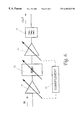
- FIG. 7 is a block diagram of a particular form of concatenation of amplifiers of the transmission system of FIG. 1 .
- the transmission system of FIG. 1 comprises a WDM transmitter 10 typically arranged to launch a plurality of optical signals that are wavelength division multiplexed into one end of an optical fibre transmission path 11 . At the far end of this path these signals are detected by a WDM receiver 12 . At spaced intervals along the transmission path 11 are inserted a set of optical amplifier modules 13 . Each optical amplifier module 13 includes at least one optical gain providing optically pumped rare-earth doped optical fibre amplifier.
- FIG. 2 shows the attenuator 22 located downstream of the amplifier 21 , but alternatively it may be located upstream of it.
- the module 13 typically includes a passive gain-flattening filter 23 whose function is to smooth out the spectral gain characteristic of the fixed gain optical waveguide optical amplifier 21 .
- the filter 23 may conveniently be a filter constructed in the manner described in EP 0 736 784 A and, though represented separately from the waveguide optical amplifier 21 in FIG. 2, in practice may be incorporated within it.
- a preferred way employs a supervisory laser (not shown) emitting at a wavelength, ⁇ 1 , within the amplification band but outside the signal band.
- the output of the supervisory laser is launched into the amplifier, and the amplitude of the portion of the output of the amplifier lying at the emission wavelength of the supervisory laser is measured.
- the amount of supervisory power launched into the amplifier is also measured, and a comparison of the two measures provides a measure of the gain provided by the amplifier at the supervisory laser wavelength.
- a feedback control loop adjusts the pump power to the amplifier to stabilise the value of this gain to a predetermined value. Stabilising the gain at one wavelength, in this instance the emission wavelength, ⁇ 1 , of the supervisory laser, stabilises the gain values at all other wavelengths in a manner that is nominally independent of the input signal power levels so long as there is sufficient pump power available.
- An alternative preferred method of clamping the gain of the amplifier 21 employs a pair of narrow-band reflectors, typically Bragg reflectors, located respectively at the upstream and downstream ends of the amplifier waveguide so as to combine to form a Fabry Pérot laser cavity lasing at a wavelength, ⁇ 1 , within the amplification band but outside the signal waveband.
- the laser oscillation means that the round-trip amplifier gain at the laser oscillation wavelength is unity. This round-trip gain is determined in part by the reflectivity of the reflectors and in part by the (single transit) gain of the amplifier, and so that gain of the amplifier at this wavelength can be set to a desired value by choice of appropriate reflectivity values for the reflectors.
- variable attenuation optical attenuator may take comprises a fibre-pigtailed module in which a linear variable neutral-density filter is mounted on a high precision linear sliding motor.
- a fibre-pigtailed module in which a linear variable neutral-density filter is mounted on a high precision linear sliding motor.
- OVA-610 Such a module is marketed by Santec under the designation OVA-610.
- Regulation of the overall gain provided by the amplifier module is provided by regulation of the optical attenuation provided by its optical attenuator 22 .
- Such regulation may for instance comprise feed-forward regulation in which the magnitude of the gain of the amplifier module is determined by the amplitude of the signal power applied to it, or it may comprise feed-back regulation in which the magnitude is determined by the amplitude of the signal power delivered by the module.
- the basic components of the feed-forward and feed-back regulation configurations are depicted respectively in FIGS. 3 and 4. In each case an optical tap 30 taps a small proportion of the optical power flowing through the amplifier and feeds it via an optical filter 31 to a photodetector 32 .
- the output of the photodetector is fed to a differential amplifier 33 where it is compared with a reference level applied to terminal 34 .
- the output of the differential amplifier is then applied as a control signal regulating the optical attenuation provided by the attenuator 22 .
- the amplifier module 13 is specifically depicted with its attenuator 22 located downstream of its optical waveguide amplifier 21 .
- This may be considered the preferred arrangement because the input optical signal power to the module is typically quite low, and hence it is generally preferable, having regard to signal-to-noise considerations, to amplify the input signal before attenuating it rather than performing these operations in the reverse order.
- module power output considerations it may be seen as desirable for the output of the module to be taken direct from the output of its optical waveguide amplifier rather than from that of its attenuator.
- the attenuator 52 of FIG. 5 performs the same function as the attenuator 22 of FIG. 2, and so these attenuators may be identical.
- the waveguide amplifiers 51 and 53 are typically doped with erbium.
- the module of FIG. 5 may additionally include a filter 54 to perform a gain-flattening function like that performed by filter 23 of the module of FIG. 2 .
- the filter 54 though represented separately from the waveguide optical amplifiers 51 and 53 in FIG. 5 as a single integer, in practice may be constituted in two parts, one incorporated within each of those amplifiers 51 and 53 .
- the conditions of operation may change so much as to make it desirable to be able to alter the gain of the upstream waveguide amplifier 51 , increasing its gain if the level of input signal power is particularly low, or decreasing it if the level is so high as to run the risk of producing saturation effects in the waveguide amplifier.
- this is entirely possible, provided that a complementary adjustment is made to the gain of the other waveguide amplifier, This complementary adjustment is such that if the gain at some wavelength, ⁇ 1 , of the waveguide amplifier 51 is change by some factor, k, then the gain at wavelength, ⁇ 1 , of waveguide amplifier 53 must be changed by the factor, 1/k.
- FIG. 6 depicts the amplifier module of FIG. 5 modified by the replacement of the fixed gain waveguide amplifiers 51 and 53 by variable gain waveguide amplifiers 61 and 63 .
- These variable gain waveguide amplifiers are depicted as being indirectly ganged via an element 64 that functions to provide the requisite complementary relationship between the values of gains at wavelength, ⁇ 1 , that they provide.
- the partitioning of the aggregate gain between these individual modules can be changed to suit changes in operating conditions without changing the overall gain spectrum of the concatenation. This partitioning is effected under the control of a network manager 70 .
Abstract
Description
Claims (16)
Priority Applications (1)
| Application Number | Priority Date | Filing Date | Title |
|---|---|---|---|
| US10/209,625 US6894829B2 (en) | 1996-06-26 | 2002-07-30 | Optical amplifier modules |
Applications Claiming Priority (3)
| Application Number | Priority Date | Filing Date | Title |
|---|---|---|---|
| GB9613413A GB2314714B (en) | 1996-06-26 | 1996-06-26 | Optical amplifier modules |
| GB9613413 | 1996-06-26 | ||
| PCT/GB1997/001701 WO1997050157A1 (en) | 1996-06-26 | 1997-06-25 | Optical amplifier modules |
Related Child Applications (1)
| Application Number | Title | Priority Date | Filing Date |
|---|---|---|---|
| US10/209,625 Continuation US6894829B2 (en) | 1996-06-26 | 2002-07-30 | Optical amplifier modules |
Publications (1)
| Publication Number | Publication Date |
|---|---|
| US6483632B1 true US6483632B1 (en) | 2002-11-19 |
Family
ID=10795928
Family Applications (2)
| Application Number | Title | Priority Date | Filing Date |
|---|---|---|---|
| US09/214,248 Expired - Lifetime US6483632B1 (en) | 1996-06-26 | 1997-06-25 | Multistage optical amplifier with gain flattening |
| US10/209,625 Expired - Lifetime US6894829B2 (en) | 1996-06-26 | 2002-07-30 | Optical amplifier modules |
Family Applications After (1)
| Application Number | Title | Priority Date | Filing Date |
|---|---|---|---|
| US10/209,625 Expired - Lifetime US6894829B2 (en) | 1996-06-26 | 2002-07-30 | Optical amplifier modules |
Country Status (6)
| Country | Link |
|---|---|
| US (2) | US6483632B1 (en) |
| EP (1) | EP0907993B1 (en) |
| JP (1) | JP2000513144A (en) |
| DE (1) | DE69723841T2 (en) |
| GB (1) | GB2314714B (en) |
| WO (1) | WO1997050157A1 (en) |
Cited By (16)
| Publication number | Priority date | Publication date | Assignee | Title |
|---|---|---|---|---|
| US20030185485A1 (en) * | 2002-03-27 | 2003-10-02 | Bennett Kevin W. | Optical processing module |
| US6687461B1 (en) * | 1998-11-04 | 2004-02-03 | Board Of Regents, The University Of Texas System | Active optical lattice filters |
| US20040100688A1 (en) * | 2002-11-18 | 2004-05-27 | Hiroshi Iizuka | Optical amplifier and optical amplifier control method |
| US20040197105A1 (en) * | 2003-02-14 | 2004-10-07 | Jds Uniphase Corporation | Variable gain multi-stage optical amplifier |
| US20040247327A1 (en) * | 2003-06-06 | 2004-12-09 | Walid Kamali | Optical receiver having an open loop automatic gain control circuit |
| US20050046925A1 (en) * | 2003-08-28 | 2005-03-03 | Macfarlane Duncan L. | Filter for selectively processing optical and other signals |
| US20050078354A1 (en) * | 2003-09-19 | 2005-04-14 | Sun-Hyok Chang | Optical fiber amplifier |
| US20050111078A1 (en) * | 2003-11-21 | 2005-05-26 | Lijie Qiao | Optical signal amplifier and method |
| US20060198017A1 (en) * | 1998-03-19 | 2006-09-07 | Fujitsu Limited | Gain and signal level adjustments of cascaded optical amplifiers |
| US20070058241A1 (en) * | 2005-09-13 | 2007-03-15 | Electronics And Telecommunications Research Institute | Optical amplification apparatus having function of flattening channel output spectrum |
| US20070133822A1 (en) * | 2005-12-14 | 2007-06-14 | May Michael R | Digital gain adjustment in a wireless receiver |
| US20080130101A1 (en) * | 2006-03-31 | 2008-06-05 | Motoki Kakui | Optical fiber amplifying module |
| US20080273876A1 (en) * | 2003-05-29 | 2008-11-06 | Paul Lundquist | Transient optical power suppressing apparatus, method, and network |
| US20080316591A1 (en) * | 2007-06-21 | 2008-12-25 | Fujitsu Limited | Optical amplifier |
| US20090225403A1 (en) * | 1996-05-28 | 2009-09-10 | Yasushi Sugaya | Multi-wavelength light amplifier |
| US20120182602A1 (en) * | 2009-09-04 | 2012-07-19 | Nokia Siemens Networks Oy | Optical fiber amplifier comprising an embedded filter and a control method with improved feedforward control performace |
Families Citing this family (17)
| Publication number | Priority date | Publication date | Assignee | Title |
|---|---|---|---|---|
| US5900969A (en) * | 1997-02-14 | 1999-05-04 | Lucent Technologies Inc. | Broadband flat gain optical amplifier |
| SE509968C2 (en) * | 1997-02-14 | 1999-03-29 | Ericsson Telefon Ab L M | Variable amplifier optical amplifier |
| EP0883255A3 (en) * | 1997-06-05 | 2002-01-09 | Nortel Networks Limited | Optically amplified WDM transmission system |
| FR2773425B1 (en) * | 1998-01-08 | 2000-02-04 | Alsthom Cge Alcatel | OPTICAL AMPLIFIER WITH OPTIMAL GAIN EXCURSION FOR DIFFERENT INPUT POWER |
| JP3779054B2 (en) | 1998-01-23 | 2006-05-24 | 富士通株式会社 | Variable optical filter |
| JP3638777B2 (en) * | 1998-02-04 | 2005-04-13 | 富士通株式会社 | Method for gain equalization and apparatus and system used to implement the method |
| US5963361A (en) * | 1998-05-22 | 1999-10-05 | Ciena Corporation | Optical amplifier having a variable attenuator controlled based on detected ASE |
| US6057959A (en) * | 1998-05-22 | 2000-05-02 | Ciena Corporation | Optical amplifier having substantially uniform spectral gain |
| US6061171A (en) * | 1998-05-22 | 2000-05-09 | Ciena Corporation | Optical amplifier having a variable attenuator controlled based on input power |
| JP2002518855A (en) * | 1998-06-19 | 2002-06-25 | ルーセント テクノロジーズ インコーポレーテッド | Method for controlling the gain tilt of an erbium-doped fiber amplifier using an intermediate attenuator |
| GB2386777A (en) * | 2002-03-19 | 2003-09-24 | Bookham Technology Plc | Polarisation insensitive optical amplifier |
| KR100442658B1 (en) * | 2002-08-14 | 2004-08-02 | 삼성전자주식회사 | Light source device for wavelength division multiplexing optical communication system |
| US7054059B1 (en) * | 2003-05-14 | 2006-05-30 | Cisco Technoloy, Inc. | Lumped Raman amplification structure for very wideband applications |
| US7999999B2 (en) * | 2004-10-29 | 2011-08-16 | Unopsys, Llc | Article comprising a multichannel optical amplified transmission system with functional upgrade capabilities and universal modules |
| JP5331950B2 (en) * | 2006-03-31 | 2013-10-30 | 株式会社メガオプト | Optical fiber laser light source |
| JP5811546B2 (en) * | 2011-02-23 | 2015-11-11 | 富士通株式会社 | Optical receiver and optical amplifier |
| US20130343751A1 (en) * | 2012-06-23 | 2013-12-26 | Pavel Mamyshev | Optical Receiver with a Wide Power Sensitivity Dynamic Range |
Citations (11)
| Publication number | Priority date | Publication date | Assignee | Title |
|---|---|---|---|---|
| US5050949A (en) * | 1990-06-22 | 1991-09-24 | At&T Bell Laboratories | Multi-stage optical fiber amplifier |
| US5115338A (en) * | 1990-05-30 | 1992-05-19 | At&T Bell Laboratories | Multi-stage optical amplifier |
| JPH08248455A (en) | 1995-03-09 | 1996-09-27 | Fujitsu Ltd | Optical amplifier for wavelength multiplexing |
| JPH09191303A (en) * | 1996-01-09 | 1997-07-22 | Kokusai Denshin Denwa Co Ltd <Kdd> | Optical transmission line |
| GB2310094A (en) | 1996-02-07 | 1997-08-13 | Fujitsu Ltd | Optical equalization and amplification of multi-wavelength light |
| US5764406A (en) * | 1996-10-01 | 1998-06-09 | Corning Incorporated | Hydrid optical amplifier having improved dynamic gain tilt |
| US5900969A (en) * | 1997-02-14 | 1999-05-04 | Lucent Technologies Inc. | Broadband flat gain optical amplifier |
| US6049413A (en) * | 1998-05-22 | 2000-04-11 | Ciena Corporation | Optical amplifier having first and second stages and an attenuator controlled based on the gains of the first and second stages |
| US6157481A (en) * | 1996-05-02 | 2000-12-05 | Fujitsu Limited | Controller which controls a variable optical attenuator to control the power level of a wavelength-multiplexed optical signal when the number of the channels are varied |
| US6172803B1 (en) * | 1997-02-18 | 2001-01-09 | Nippon Telegraph And Telephone Corporation | Optical amplifier and transmission system using the same |
| US6215584B1 (en) * | 1999-05-10 | 2001-04-10 | Jds Uniphase Inc. | Input independent tilt free actively gain flattened broadband amplifier |
Family Cites Families (15)
| Publication number | Priority date | Publication date | Assignee | Title |
|---|---|---|---|---|
| US5099489A (en) * | 1989-09-15 | 1992-03-24 | At&T Bell Laboratories | Apparatus comprising a quantum well device |
| JPH03206427A (en) * | 1990-01-08 | 1991-09-09 | Mitsubishi Electric Corp | Fiber type optical amplifier |
| US5187610A (en) * | 1991-12-19 | 1993-02-16 | At&T Bell Laboratories | Low noise, optical amplifier having post-amplification loss element |
| JPH05343784A (en) * | 1992-06-09 | 1993-12-24 | Nippon Telegr & Teleph Corp <Ntt> | Light amplifier |
| JPH0653588A (en) * | 1992-07-31 | 1994-02-25 | Nec Corp | Optical fiber amplifier |
| JPH07281219A (en) * | 1994-04-14 | 1995-10-27 | Matsushita Electric Ind Co Ltd | Optical fiber amplifier |
| PE41196A1 (en) * | 1994-07-25 | 1996-12-17 | Pirelli Cavi Spa | AMPLIFIED TELECOMMUNICATION SYSTEM FOR MULTIPLEX TRANSMISSIONS BY WAVE LENGTH DIVISION, ABLE TO LIMIT THE VARIATIONS IN THE OUTPUT POWER |
| US6400497B1 (en) * | 1994-11-16 | 2002-06-04 | Oki Electric Industry Co., Ltd. | Optical fiber amplifier |
| JPH09321701A (en) * | 1996-05-31 | 1997-12-12 | Fujitsu Ltd | Optical communication system and optical amplifier |
| SE509968C2 (en) * | 1997-02-14 | 1999-03-29 | Ericsson Telefon Ab L M | Variable amplifier optical amplifier |
| US6049418A (en) * | 1998-02-06 | 2000-04-11 | Lucent Technologies, Inc. | Noise figure in optical amplifiers with a split-band architecture |
| US6061171A (en) * | 1998-05-22 | 2000-05-09 | Ciena Corporation | Optical amplifier having a variable attenuator controlled based on input power |
| JP3740849B2 (en) * | 1998-07-13 | 2006-02-01 | 日立電線株式会社 | Optical amplifier |
| JP3134854B2 (en) * | 1998-09-07 | 2001-02-13 | 日本電気株式会社 | Optical amplifier |
| US6236499B1 (en) * | 1999-04-15 | 2001-05-22 | Nortel Networks Limited | Highly scalable modular optical amplifier based subsystem |
-
1996
- 1996-06-26 GB GB9613413A patent/GB2314714B/en not_active Revoked
-
1997
- 1997-06-25 EP EP97928354A patent/EP0907993B1/en not_active Expired - Lifetime
- 1997-06-25 WO PCT/GB1997/001701 patent/WO1997050157A1/en active IP Right Grant
- 1997-06-25 US US09/214,248 patent/US6483632B1/en not_active Expired - Lifetime
- 1997-06-25 DE DE69723841T patent/DE69723841T2/en not_active Expired - Lifetime
- 1997-06-25 JP JP10502547A patent/JP2000513144A/en active Pending
-
2002
- 2002-07-30 US US10/209,625 patent/US6894829B2/en not_active Expired - Lifetime
Patent Citations (13)
| Publication number | Priority date | Publication date | Assignee | Title |
|---|---|---|---|---|
| US5115338A (en) * | 1990-05-30 | 1992-05-19 | At&T Bell Laboratories | Multi-stage optical amplifier |
| US5050949A (en) * | 1990-06-22 | 1991-09-24 | At&T Bell Laboratories | Multi-stage optical fiber amplifier |
| US6055092A (en) * | 1995-03-09 | 2000-04-25 | Fujitsu Limited | Multi-wavelength light amplifier |
| JPH08248455A (en) | 1995-03-09 | 1996-09-27 | Fujitsu Ltd | Optical amplifier for wavelength multiplexing |
| JPH09191303A (en) * | 1996-01-09 | 1997-07-22 | Kokusai Denshin Denwa Co Ltd <Kdd> | Optical transmission line |
| GB2310094A (en) | 1996-02-07 | 1997-08-13 | Fujitsu Ltd | Optical equalization and amplification of multi-wavelength light |
| US6157481A (en) * | 1996-05-02 | 2000-12-05 | Fujitsu Limited | Controller which controls a variable optical attenuator to control the power level of a wavelength-multiplexed optical signal when the number of the channels are varied |
| US6198572B1 (en) * | 1996-05-02 | 2001-03-06 | Fujitsu Limited | Controller which controls a variable optical attenuator to control the power level of a wavelength-multiplexed optical signal when the number of channels are varied |
| US5764406A (en) * | 1996-10-01 | 1998-06-09 | Corning Incorporated | Hydrid optical amplifier having improved dynamic gain tilt |
| US5900969A (en) * | 1997-02-14 | 1999-05-04 | Lucent Technologies Inc. | Broadband flat gain optical amplifier |
| US6172803B1 (en) * | 1997-02-18 | 2001-01-09 | Nippon Telegraph And Telephone Corporation | Optical amplifier and transmission system using the same |
| US6049413A (en) * | 1998-05-22 | 2000-04-11 | Ciena Corporation | Optical amplifier having first and second stages and an attenuator controlled based on the gains of the first and second stages |
| US6215584B1 (en) * | 1999-05-10 | 2001-04-10 | Jds Uniphase Inc. | Input independent tilt free actively gain flattened broadband amplifier |
Non-Patent Citations (4)
| Title |
|---|
| Dentai et al., "Electrically Tunable Semiconductor Fabry-Perot Filter", IEEE Photonics Technology Letters, vol. 6, No. 5, May 1994, pp. 629-631.* * |
| Desurvire, Emmanuel. "Erbium-Doped Fiber Amplifiers, Principles and Applications", 1994, pp. 469-472.* * |
| Jolley et al., "Out-of-band electronic gain clamping for a variable gain and output power EDFA with low dynaic gain tilt", OFC'97 Technical Digest, 1997, pp. 134-135.* * |
| Zhou; "Power Management System Design Modelling of Optical Multi-Wavelength Transport Networks", IEEE, Nov. 28, 1994, pp. 1503-1507. |
Cited By (36)
| Publication number | Priority date | Publication date | Assignee | Title |
|---|---|---|---|---|
| US20090225403A1 (en) * | 1996-05-28 | 2009-09-10 | Yasushi Sugaya | Multi-wavelength light amplifier |
| US8699126B2 (en) | 1996-05-28 | 2014-04-15 | Fujitsu Limited | Multi-wavelength light amplifier |
| US8320040B2 (en) | 1996-05-28 | 2012-11-27 | Fujitsu Limited | Multi-wavelength light amplifier |
| US8004752B2 (en) | 1996-05-28 | 2011-08-23 | Fujitsu Limited | Multi-wavelength light amplifier |
| US20110164309A1 (en) * | 1998-03-19 | 2011-07-07 | Fujitsu Limited | Gain and signal level adjustments of cascaded optical amplifiers |
| US20100272445A1 (en) * | 1998-03-19 | 2010-10-28 | Fujitsu Limited | Gain and signal level adjustments of cascaded optical amplifiers |
| US8547629B2 (en) | 1998-03-19 | 2013-10-01 | Fujitsu Limited | Gain and signal level adjustments of cascaded optical amplifiers |
| US20060198017A1 (en) * | 1998-03-19 | 2006-09-07 | Fujitsu Limited | Gain and signal level adjustments of cascaded optical amplifiers |
| US7969648B2 (en) * | 1998-03-19 | 2011-06-28 | Fujitsu Limited | Gain and signal level adjustments of cascaded optical amplifiers |
| US7924499B2 (en) | 1998-03-19 | 2011-04-12 | Fujitsu Limited | Gain and signal level adjustments of cascaded optical amplifiers |
| US6687461B1 (en) * | 1998-11-04 | 2004-02-03 | Board Of Regents, The University Of Texas System | Active optical lattice filters |
| US20030185485A1 (en) * | 2002-03-27 | 2003-10-02 | Bennett Kevin W. | Optical processing module |
| US7202997B2 (en) * | 2002-11-18 | 2007-04-10 | Fujitsu Limited | Optical amplifier and optical amplifier control method |
| US20040100688A1 (en) * | 2002-11-18 | 2004-05-27 | Hiroshi Iizuka | Optical amplifier and optical amplifier control method |
| US20040197105A1 (en) * | 2003-02-14 | 2004-10-07 | Jds Uniphase Corporation | Variable gain multi-stage optical amplifier |
| US7589889B2 (en) * | 2003-05-29 | 2009-09-15 | Ciena Corporation | Transient optical power suppressing apparatus, method, and network |
| US20080273876A1 (en) * | 2003-05-29 | 2008-11-06 | Paul Lundquist | Transient optical power suppressing apparatus, method, and network |
| US20040247327A1 (en) * | 2003-06-06 | 2004-12-09 | Walid Kamali | Optical receiver having an open loop automatic gain control circuit |
| US7599629B2 (en) * | 2003-06-06 | 2009-10-06 | Scientific-Atlanta, Inc. | Optical receiver having an open loop automatic gain control circuit |
| US20050046925A1 (en) * | 2003-08-28 | 2005-03-03 | Macfarlane Duncan L. | Filter for selectively processing optical and other signals |
| US7042657B2 (en) | 2003-08-28 | 2006-05-09 | Board Of Regents The University Of Texas System | Filter for selectively processing optical and other signals |
| US7215462B2 (en) | 2003-08-28 | 2007-05-08 | Board Of Regents, The University Of Texas System | Filter for selectively processing optical and other signals |
| US20060209391A1 (en) * | 2003-08-28 | 2006-09-21 | Board Of Regents, The University Of Texas System | Filter for selectively processing optical and other signals |
| US20050078354A1 (en) * | 2003-09-19 | 2005-04-14 | Sun-Hyok Chang | Optical fiber amplifier |
| US20050111078A1 (en) * | 2003-11-21 | 2005-05-26 | Lijie Qiao | Optical signal amplifier and method |
| US7324268B2 (en) | 2003-11-21 | 2008-01-29 | Bti Photonic Systems Inc. | Optical signal amplifier and method |
| US20070058241A1 (en) * | 2005-09-13 | 2007-03-15 | Electronics And Telecommunications Research Institute | Optical amplification apparatus having function of flattening channel output spectrum |
| US7856073B2 (en) * | 2005-12-14 | 2010-12-21 | Sigma Tel, Inc. | Digital gain adjustment in a wireless receiver |
| US20070133822A1 (en) * | 2005-12-14 | 2007-06-14 | May Michael R | Digital gain adjustment in a wireless receiver |
| US8098424B2 (en) * | 2006-03-31 | 2012-01-17 | Sumitomo Electric Industries, Ltd. | Optical fiber amplifying module |
| US8493653B2 (en) | 2006-03-31 | 2013-07-23 | Megaopto Co., Ltd. | Multi-stage optical fiber amplifier with high gain and low duty cycle |
| US20080130101A1 (en) * | 2006-03-31 | 2008-06-05 | Motoki Kakui | Optical fiber amplifying module |
| US7929201B2 (en) * | 2007-06-21 | 2011-04-19 | Fujitsu Limited | Multistage optical amplifier with gain control using pump ratio |
| US20080316591A1 (en) * | 2007-06-21 | 2008-12-25 | Fujitsu Limited | Optical amplifier |
| US20120182602A1 (en) * | 2009-09-04 | 2012-07-19 | Nokia Siemens Networks Oy | Optical fiber amplifier comprising an embedded filter and a control method with improved feedforward control performace |
| US8908265B2 (en) * | 2009-09-04 | 2014-12-09 | Xieon Networks S.A.R.L. | Optical fiber amplifier comprising an embedded filter and a control method with improved feedforward control performance |
Also Published As
| Publication number | Publication date |
|---|---|
| EP0907993A1 (en) | 1999-04-14 |
| JP2000513144A (en) | 2000-10-03 |
| EP0907993B1 (en) | 2003-07-30 |
| DE69723841D1 (en) | 2003-09-04 |
| DE69723841T2 (en) | 2004-03-04 |
| GB2314714A (en) | 1998-01-07 |
| WO1997050157A1 (en) | 1997-12-31 |
| GB9613413D0 (en) | 1996-08-28 |
| US20020196528A1 (en) | 2002-12-26 |
| GB2314714B (en) | 2000-04-05 |
| US6894829B2 (en) | 2005-05-17 |
Similar Documents
| Publication | Publication Date | Title |
|---|---|---|
| US6483632B1 (en) | Multistage optical amplifier with gain flattening | |
| US6215584B1 (en) | Input independent tilt free actively gain flattened broadband amplifier | |
| US6038061A (en) | Doped fiber amplifier using bidirectional pumping with pump lights having different frequencies | |
| CN100454689C (en) | Optical amplifier and a method of controlling the optical amplifier | |
| US6459527B1 (en) | Optical amplifier apparatus and control method thereof, and optical transmission system using optical amplifier apparatus | |
| US6963681B2 (en) | Automatic raman gain control | |
| EP1037337B1 (en) | Optical amplifier | |
| RU2202151C2 (en) | Pump oscillator wavelength adjustment for optical amplifiers and its use in wavelength- division multiplex systems | |
| US6757099B2 (en) | Optical power transient control scheme for EDFA amplifiers | |
| CA2341726A1 (en) | Gain control and shaping of edfas via dual cavity gain control | |
| RU2176433C1 (en) | Procedure setting level of optical signals | |
| US6791745B2 (en) | Optical communication system | |
| US7158288B2 (en) | Long-wavelength-band gain-controlled optical amplifier | |
| US7365903B2 (en) | Apparatus and method for all-optical control of gain and gain flattening on an optical amplifier | |
| US6151156A (en) | Optical fibre amplifier and transmission system with optical fibre-amplifier | |
| KR100305757B1 (en) | Gain-Flat Maintenance Optical Amplifiers for Wavelength Division Multiplexing Systems | |
| TW369613B (en) | Pump wavelength tuning of optical amplifiers and use of same in wavelength division multiplexed systems | |
| JP2004511007A (en) | Raman amplifier | |
| JP2000156671A (en) | Wdm transmission system having plural amplifiers | |
| JP2000031572A (en) | Optical amplifier | |
| KR20000039037A (en) | Optical amplifier for wavelength division optical transmission apparatus |
Legal Events
| Date | Code | Title | Description |
|---|---|---|---|
| AS | Assignment |
Owner name: NORTEL NETWORKS CORPORATION, CANADA Free format text: ASSIGNMENT OF ASSIGNORS INTEREST;ASSIGNORS:JOLLEY, NIGEL EDWARD;DAVIS, FIONA;EPWORTH, RICHARD EDWARD;REEL/FRAME:010329/0728;SIGNING DATES FROM 19990920 TO 19990923 |
|
| AS | Assignment |
Owner name: NORTEL NETWORKS CORPORATION, CANADA Free format text: CHANGE OF NAME;ASSIGNOR:NORTHERN TELECOM LIMITED;REEL/FRAME:010567/0001 Effective date: 19990429 |
|
| AS | Assignment |
Owner name: NORTEL NETWORKS LIMITED, CANADA Free format text: CHANGE OF NAME;ASSIGNOR:NORTEL NETWORKS CORPORATION;REEL/FRAME:011195/0706 Effective date: 20000830 Owner name: NORTEL NETWORKS LIMITED,CANADA Free format text: CHANGE OF NAME;ASSIGNOR:NORTEL NETWORKS CORPORATION;REEL/FRAME:011195/0706 Effective date: 20000830 |
|
| AS | Assignment |
Owner name: NORTEL NETWORKS LIMITED, CANADA Free format text: CHANGE OF NAME;ASSIGNOR:NORTEL NETWORKS CORPORATION;REEL/FRAME:013341/0159 Effective date: 20000501 |
|
| STCF | Information on status: patent grant |
Free format text: PATENTED CASE |
|
| AS | Assignment |
Owner name: JPMORGAN CHASE BANK N.A., AS COLLATERAL AGENT, NEW Free format text: SECURITY AGREEMENT;ASSIGNOR:NORTEL NETWORKS LIMITED;REEL/FRAME:017198/0151 Effective date: 20060214 |
|
| FPAY | Fee payment |
Year of fee payment: 4 |
|
| AS | Assignment |
Owner name: NORTEL NETWORKS LIMITED, CANADA Free format text: RELEASE OF PATENT SECURITY AGREEMENT;ASSIGNOR:JPMORGAN CHASE BANK N.A., AS COLLATERAL AGENT;REEL/FRAME:017914/0962 Effective date: 20060705 |
|
| AS | Assignment |
Owner name: CIENA LUXEMBOURG S.A.R.L.,LUXEMBOURG Free format text: ASSIGNMENT OF ASSIGNORS INTEREST;ASSIGNOR:NORTEL NETWORKS LIMITED;REEL/FRAME:024213/0653 Effective date: 20100319 Owner name: CIENA LUXEMBOURG S.A.R.L., LUXEMBOURG Free format text: ASSIGNMENT OF ASSIGNORS INTEREST;ASSIGNOR:NORTEL NETWORKS LIMITED;REEL/FRAME:024213/0653 Effective date: 20100319 |
|
| AS | Assignment |
Owner name: CIENA CORPORATION,MARYLAND Free format text: ASSIGNMENT OF ASSIGNORS INTEREST;ASSIGNOR:CIENA LUXEMBOURG S.A.R.L.;REEL/FRAME:024252/0060 Effective date: 20100319 Owner name: CIENA CORPORATION, MARYLAND Free format text: ASSIGNMENT OF ASSIGNORS INTEREST;ASSIGNOR:CIENA LUXEMBOURG S.A.R.L.;REEL/FRAME:024252/0060 Effective date: 20100319 |
|
| FPAY | Fee payment |
Year of fee payment: 8 |
|
| FPAY | Fee payment |
Year of fee payment: 12 |
|
| AS | Assignment |
Owner name: DEUTSCHE BANK AG NEW YORK BRANCH, NEW YORK Free format text: SECURITY INTEREST;ASSIGNOR:CIENA CORPORATION;REEL/FRAME:033329/0417 Effective date: 20140715 |
|
| AS | Assignment |
Owner name: BANK OF AMERICA, N.A., AS ADMINISTRATIVE AGENT, NO Free format text: PATENT SECURITY AGREEMENT;ASSIGNOR:CIENA CORPORATION;REEL/FRAME:033347/0260 Effective date: 20140715 |
|
| AS | Assignment |
Owner name: CIENA CORPORATION, MARYLAND Free format text: RELEASE BY SECURED PARTY;ASSIGNOR:DEUTSCHE BANK AG NEW YORK BRANCH;REEL/FRAME:050938/0389 Effective date: 20191028 |
|
| AS | Assignment |
Owner name: BANK OF AMERICA, N.A., AS COLLATERAL AGENT, ILLINO Free format text: PATENT SECURITY AGREEMENT;ASSIGNOR:CIENA CORPORATION;REEL/FRAME:050969/0001 Effective date: 20191028 |
|
| AS | Assignment |
Owner name: CIENA CORPORATION, MARYLAND Free format text: RELEASE BY SECURED PARTY;ASSIGNOR:BANK OF AMERICA, N.A.;REEL/FRAME:065630/0232 Effective date: 20231024 |