US6493123B1 - Modulated-retroreflector based optical identification system - Google Patents
Modulated-retroreflector based optical identification system Download PDFInfo
- Publication number
- US6493123B1 US6493123B1 US09/427,830 US42783099A US6493123B1 US 6493123 B1 US6493123 B1 US 6493123B1 US 42783099 A US42783099 A US 42783099A US 6493123 B1 US6493123 B1 US 6493123B1
- Authority
- US
- United States
- Prior art keywords
- modulated
- reflected beam
- identification system
- optical identification
- detector
- Prior art date
- Legal status (The legal status is an assumption and is not a legal conclusion. Google has not performed a legal analysis and makes no representation as to the accuracy of the status listed.)
- Expired - Fee Related
Links
Images

Classifications
-
- H—ELECTRICITY
- H04—ELECTRIC COMMUNICATION TECHNIQUE
- H04B—TRANSMISSION
- H04B10/00—Transmission systems employing electromagnetic waves other than radio-waves, e.g. infrared, visible or ultraviolet light, or employing corpuscular radiation, e.g. quantum communication
- H04B10/25—Arrangements specific to fibre transmission
- H04B10/2587—Arrangements specific to fibre transmission using a single light source for multiple stations
-
- H—ELECTRICITY
- H04—ELECTRIC COMMUNICATION TECHNIQUE
- H04B—TRANSMISSION
- H04B10/00—Transmission systems employing electromagnetic waves other than radio-waves, e.g. infrared, visible or ultraviolet light, or employing corpuscular radiation, e.g. quantum communication
- H04B10/50—Transmitters
- H04B10/516—Details of coding or modulation
- H04B10/532—Polarisation modulation
Definitions
- the present invention generally relates to identification systems and more particularly to an optical identification system that has a low probability of being intercepted.
- Determining the position of personnel and vehicles in the field can be difficult due to battlefield conditions. Personnel and vehicles may be camouflaged such that a visual identification may be difficult. Additionally, personnel and vehicles may be turned away from the battlefield commander such that markings on the vehicle cannot be seen and a positive identification cannot be made.
- Prior art optical identification systems have relied upon a laser beam for interrogation of units.
- the battlefield commander will direct a laser beam from a transmitter onto a target located on the desired unit.
- the target will respond by transmitting its own laser back to a receiver whereby information contained within the laser beam about the identification of the unit will be decoded.
- the target may modify the transmitted beam and return the modified beam to the battlefield commander whereby the modified beam will be decoded in order to determine the identification of the unit.
- a problem associated with the prior art laser identification systems is that the systems are bulky and highly complex. In this respect, the transmitter and target are highly complex and prone to failure.
- the lasers used in the prior art systems are bulky and consume large amounts of power thereby needing to be cooled and making it difficult to implement a portable system for the battlefield.
- a problem associated with the prior art optical identification systems is that the laser beam is subject to divergence and scattering thereby allowing such systems to be vulnerable to detection and jamming by the enemy.
- the present invention addresses the problems associated with the prior art identification systems by providing a system that provides covert identification of units on the battlefield.
- the present invention provides an optical identification system that is easily transportable and consumes a low amount of power.
- the present invention provides a laser based optical identification system that is extremely difficult to detect and jam.
- An optical identification system for identifying a vehicle.
- the system comprises a laser source for generating a transmitted beam and a reflector in optical communication therewith.
- the reflector is operative to reflect the transmitted beam to thereby generate a reflected beam.
- the system further includes a shutter in optical communication with the reflected beam and operative to modulate the polarization of the reflected beam with identification information to thereby generate a modulated reflected beam.
- the optical identification system further includes a detector in optical communication with the reflected beam. The detector is operative to pass the modulated reflected beam and decode the identification information modulated thereon.
- the detector of the optical identification system will include a polarizer to pass the correct polarization of the reflected beam.
- the polarizer is configured to pass the modulated reflected beam when the polarization of the modulated reflected beam matches the polarization modulated by the shutter.
- the detector of the optical identification system further includes an optical filter that is operative to only pass the modulated reflected beam when the wavelength thereof matches the wavelength of the transmitted beam.
- the laser source and the detector will be mounted on a common platform such as a pair of binoculars to form a sighting device.
- the laser is a low power (20 mW) eye safe laser that emits light having a wavelength of about 1.55 ⁇ m.
- the shutter and the reflector of the present invention will be mounted as a target upon the vehicle to be identified.
- the shutter will be an electronically driven liquid crystal that modulates the reflected beam by rotating the polarization thereof.
- the shutter will modulate the polarization with a prescribed code that is the identification information.
- the identification information corresponds to the identity of the vehicle.
- the reflector is typically a corner cube operative to reflect the transmitted beam back to the source.
- the shutter will be mounted in front of the corner cube such that the transmitted beam must pass through the shutter before striking the reflector.
- the detector of the present invention is a photodetector operative to convert the modulated reflected beam into an electrical signal.
- the detector is configured to decode the modulated reflected beam to determine the identification information.
- a method of optical identification with a laser source, a shutter, a reflector, a polarizer and a detector comprises generating a transmitted beam with the laser source.
- the transmitted beam is reflected with the reflector to generate a reflected beam.
- the polarization of the reflected beam is modulated with identification information by the shutter to thereby generate a modulated reflected beam.
- the modulated reflected beam is passed by the polarizer when the polarization of the modulated reflected beam matches the polarization modulated by the shutter.
- the modulated reflected beam is decoded with the detector to determine the identification information.
- the reflector and the shutter are mounted on a vehicle and the identification information modulated on the reflected beam corresponds to an identification code of the vehicle.
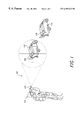
- FIG. 1 perspectively illustrates an optical identification system constructed in accordance with a preferred embodiment of the present invention.
- FIG. 2 is a block level diagram of the optical identification system shown in FIG. 1 .
- FIG. 1 perspectively illustrates an optical identification system 10 used by a soldier 12 to identify a vehicle 14 .
- the optical identification system 10 comprises a sighting unit 16 used to locate a target 18 mounted on the vehicle 14 .
- the soldier 12 uses an ocular of the sighting unit 16 to identify the target 18 on the vehicle 14 .
- the sighting unit 16 includes a laser 20 for generating a transmitted laser beam 22 .
- the laser 20 is co-aligned with the ocular of the sighting unit such that as the soldier 12 sights the target 18 with the ocular, the laser 20 will direct the laser beam 22 toward the target 18 .
- the laser 20 is a low power 20-mW continuous wave diode laser.
- the laser 20 operates in the near infrared and produces a wavelength of approximately 1.55 ⁇ m. Accordingly, the laser 20 is entirely eye safe and is outside the passband of many deployed military infrared systems.
- the laser 20 does not require any cooling and/or temperature control thereby allowing the laser 20 to be easily transportable.
- a single lens (not shown) is placed in front of the laser 20 , in order to collimate the transmitted laser beam 22 .
- the laser 20 transmits the transmitted laser beam 22 to the target 18 mounted on the vehicle 14 .
- the target 18 includes a reflector 24 that is operative to reflect the transmitted laser beam 22 .
- the reflector 24 is a corner cube having three mirrored surfaces each at 90 degrees to one another (i.e., similar to a corner of a room).
- the reflector 24 is operative to precisely reflect the transmitted laser beam 22 back to the sighting unit 16 .
- the reflector 24 reflects the transmitted laser beam 22 precisely back in the direction of transmission. Any beam reflected by the reflector 24 is not affected by the relative angle or motion of the reflector 24 within a cone of approximately 45 degrees. Therefore, the reflector 24 does not scatter the transmitted laser beam 22 after reflection.
- the reflector 24 may be a planar reflective surface or have other configurations such that the transmitted laser beam 22 is precisely reflected back to the sighting unit 16 .
- the target 18 includes a shutter 26 disposed in the optical path of the transmitted laser beam 22 .
- the shutter 26 is disposed between the laser 20 and the reflector 24 such that the transmitted laser beam 22 must pass therethrough before striking the reflector 24 .
- the shutter 26 is an electrically driven liquid crystal operated by a small electronic shutter controller 28 .
- the shutter controller 28 is powered by a battery and consumes a minimal amount of power.
- the shutter 26 is a flat window-like liquid crystal structure that rotates the polarization of the transmitted beam 22 depending on the voltage applied to it.
- the shutter controller 28 is operative to apply a voltage to the shutter 26 such that the shutter 26 can rotate the polarization of any beam transmitted therethrough.
- the polarization of the reflected beam 30 may be rotated a total of 90 degrees by the shutter 26 depending on the voltage applied thereto by shutter controller 28 .
- the shutter controller 28 applies a voltage to the shutter 26 in a manner that will modulate the reflected beam's 30 polarization with a prescribed code or pattern.
- the shutter 26 operates in a continuous, closed loop mode by the shutter controller 28 such that the code applied to shutter 26 is repeated.
- the shutter 26 modulates the polarization of the reflected beam 30 with a prescribed code or pattern.
- the code or pattern can correspond to a binary representation of a number or name of the vehicle 14 that the target 18 is mounted upon.
- the shutter controller 28 of each target 18 will operate a respective shutter 26 with a unique code such that the reflected beam 30 of each target 18 will be modulated with the unique code.
- the reflected beam 30 is returned precisely to the sighting unit 16 by the reflector 24 .
- the sighting unit 16 includes a photodetector 32 , an optical filter 41 and a polarizer 40 in optical communication with the reflected beam 30 .
- the optical filter 41 will only pass light of a prescribed wavelength. Accordingly, the optical filter 41 will only pass light having a wavelength corresponding to the wavelength of light generated by the laser 20 .
- the optical filter 41 will pass the reflected beam 30 to the photodetector 32 if the light has a wavelength 1.55 ⁇ m corresponding to the wavelength of light generated by the laser source 20 .
- the polarizer 40 will only pass light with a correct polarization. Specifically, the polarizer 40 will pass the reflected beam 30 if the light has the same polarization generated by the shutter 26 . Therefore, the reflected beam 30 will pass to the photodetector 32 only when the shutter 26 has modulated the polarization of the reflected beam 30 to match the polarization of the polarizer 40 . Therefore, a series of pulses of the reflected beam 30 with the same polarization as the polarizer 40 will strike the photodetector 32 . If the polarization of the reflected beam 30 is crossed to the polarization as the polarizer 40 (i.e. the polarization of the reflected beam 30 has not been modulated by the shutter 26 ), then the reflected beam 30 will not pass through the polarizer 40 and will not strike the photodetector 32 .
- the photodetector 32 will detect the pulses of the reflected beam 30 and convert the same into an electrical signal that is passed onto the photodetector controller 34 .
- the photodetector 32 is operative to detect the wavelength of the pulses of the reflected beam 30 . In the preferred embodiment of the present invention, the photodetector 32 detects light having a wavelength of about 1.55 ⁇ m.
- the controller 34 is operative to decode the pulses of the reflected beam 30 in order to form the unique code from the target 18 .
- the photodetector controller 34 is in electrical communication with a video display 36 and an audio output 38 . In this respect, the photodetector controller 34 is operative to display the code from the target 18 and/or output an audio signal at audio output 38 .
- the display 36 may be a LED display that displays a code word to the soldier 12 .
- the audio output 38 may broadcast a recorded message to a pair of audio headsets worn by the soldier 12 .
- the soldier 12 aims the sighting device 16 at the target 18 mounted on the vehicle 14 .
- the laser 20 transmits the transmitted beam 22 to the target 18 .
- the reflector 24 reflects the transmitted beam 22 to generate the reflected beam 30 .
- the shutter 26 modulates the polarization of the reflected beam 30 with a code from the shutter controller 28 . After the shutter 26 modulates the polarization of the reflected beam 30 , the reflected beam is returned to the sighting unit 16 .
- the reflected beam 30 is focused onto the photodetector 32 by the optical filter 41 and the polarizer 40 when the polarization and the wavelength of the reflected beam 30 are correct.
- the photodetector 32 detects the reflected beam 30 and decodes the identification information.
- the code is either visually presented on the display 36 and/or presented at audio output 38 .
- the solder 12 can aim the sighting device 16 of the optical identification system 10 on multiple vehicles 14 on the battlefield to determine their identity.
- the optical identification system 10 is ideally suited for battlefield applications because it offers little chance for interception of information during transfer. Specifically, the reflector 24 precisely reflects the reflected beam 30 to the photodetector 32 . Tests with the optical identification system 10 constructed in accordance with the present invention have been performed and have proven that both the audio and visual codes can be transmitted over distances exceeding one mile.
- the system 10 may be used as an interrogator to determine whether the vehicle 14 is friend or foe. Specifically, if the target 18 does not respond with the correct code, the soldier 12 then knows that the vehicle 14 is the enemy. Accordingly, the optical identification system 10 can be used to determine friendly forces such that fratricide can be reduced.
- the present invention can additionally be used in air-to-ground identification.
- the sighting unit 16 may be mounted on an aircraft with a stabilized platform (i.e., gimbals) to interrogate ground units having a target 18 .
- a stabilized platform i.e., gimbals
- air-to-air identification and satellite-to-air identification may be possible.
- the present invention has application in other types of fields rather than just military operations.
- the optical identification system 10 may be used in civilian applications such as search and rescue operations, field level communications, unattended ground sensor data retrieval and communications to miniature unmanned aerial vehicles where weight and power consumption are important.
- the target 18 may be used as a remote bar code generator for applications in which visibility over long distances is a limiting factor. Further, the target 18 of the optical identification system 10 is ideally suited for applications where standard RF communications present a safety hazard. It will be recognized by those of ordinary skill in the art that because the shutter 26 is electrically driven, it may be reprogrammed to transmit other coded messages such as emergency requests, inventory lists or even voice transmissions.
- the shutter 26 may be equipped with a sensor for determining whether a transmitted beam 22 is being projected thereon.
- the beam 22 would be coded such that the shutter would only begin operating if the code of the beam 22 matches a prescribed code for the target 18 . Accordingly, the target 18 would only create a modulated reflected beam 30 if the code of the transmitted beam 22 were correct thereby inhibiting detection from enemy forces.
Abstract
Description
Claims (34)
Priority Applications (1)
| Application Number | Priority Date | Filing Date | Title |
|---|---|---|---|
| US09/427,830 US6493123B1 (en) | 1999-10-27 | 1999-10-27 | Modulated-retroreflector based optical identification system |
Applications Claiming Priority (1)
| Application Number | Priority Date | Filing Date | Title |
|---|---|---|---|
| US09/427,830 US6493123B1 (en) | 1999-10-27 | 1999-10-27 | Modulated-retroreflector based optical identification system |
Publications (1)
| Publication Number | Publication Date |
|---|---|
| US6493123B1 true US6493123B1 (en) | 2002-12-10 |
Family
ID=23696475
Family Applications (1)
| Application Number | Title | Priority Date | Filing Date |
|---|---|---|---|
| US09/427,830 Expired - Fee Related US6493123B1 (en) | 1999-10-27 | 1999-10-27 | Modulated-retroreflector based optical identification system |
Country Status (1)
| Country | Link |
|---|---|
| US (1) | US6493123B1 (en) |
Cited By (31)
| Publication number | Priority date | Publication date | Assignee | Title |
|---|---|---|---|---|
| US20050105914A1 (en) * | 2003-11-17 | 2005-05-19 | Chen Chungte W. | Method for identifying an interrogated object using a dynamic optical tag identification system |
| US20050135812A1 (en) * | 2003-12-18 | 2005-06-23 | Pease David M. | Laser-based communications with a remote information source |
| US20060060651A1 (en) * | 2004-09-23 | 2006-03-23 | Mcintyre Timothy J | Laser scanning system for object monitoring |
| US20060266917A1 (en) * | 2005-05-23 | 2006-11-30 | Baldis Sisinio F | Wireless Power Transmission System |
| US20070177880A1 (en) * | 2004-03-15 | 2007-08-02 | Nir Karasikov | Retromodulation-based data communication |
| US20070205890A1 (en) * | 2006-03-06 | 2007-09-06 | Brown Karen K | Location awareness system |
| US7484857B2 (en) | 2004-11-30 | 2009-02-03 | Massachusetts Institute Of Technology | Light modulating mirror device and array |
| US20090034985A1 (en) * | 2007-07-30 | 2009-02-05 | Fattal David A | Optical interconnect |
| US20090058712A1 (en) * | 2002-02-01 | 2009-03-05 | Cubic Corporation | Secure covert combat identification friend-or-foe (IFF) system for the dismounted soldier |
| US20090079616A1 (en) * | 2007-09-20 | 2009-03-26 | Lockheed Martin Corporation | Covert long range positive friendly identification system |
| US20090103925A1 (en) * | 2005-09-27 | 2009-04-23 | Ortal Alpert | Directional Light Transmitter and Receiver |
| US20090116025A1 (en) * | 2007-11-06 | 2009-05-07 | Cubic Corporation | Field test of a retro-reflector and detector assembly |
| US20090116850A1 (en) * | 2007-10-29 | 2009-05-07 | Cubic Corporation | Resonant quantum well modulator driver |
| US20090202254A1 (en) * | 2008-02-12 | 2009-08-13 | Arun Kumar Majumdar | Wide field-of-view amplified fiber-retro for secure high data rate communications and remote data transfer |
| WO2009121003A1 (en) * | 2008-03-27 | 2009-10-01 | Cubic Corporation | Modulating retro-reflector optical communication using polarization differential signaling |
| US20090285583A1 (en) * | 2008-05-15 | 2009-11-19 | Winker Bruce K | Snr enhancement in modulating retroreflector optical communication links |
| US20100028021A1 (en) * | 2008-07-30 | 2010-02-04 | Shimada Shigehito | Method and apparatus for visible light communication using single light source |
| US20100054755A1 (en) * | 2008-09-01 | 2010-03-04 | Samsung Electronics Co., Ltd. | Method and apparatus for optical communication using a retro-reflector |
| US20100135670A1 (en) * | 2008-11-21 | 2010-06-03 | Cubic Corporation | Phase-modulating communication device |
| CN101822127A (en) * | 2007-10-12 | 2010-09-01 | 皇家飞利浦电子股份有限公司 | Sensing coded light using retro reflectors |
| US20100320362A1 (en) * | 2008-01-03 | 2010-12-23 | Ortal Alpert | Wireless laser power transmitter |
| DE102009040863A1 (en) * | 2009-09-10 | 2011-03-24 | Carl Zeiss Ag | Device, method and reflector arrangement for position determination |
| US20110231035A1 (en) * | 2010-03-22 | 2011-09-22 | Lasermax,, Inc. | System and method for friend or foe identification |
| US8224189B1 (en) | 2007-02-02 | 2012-07-17 | Sunlight Photonics Inc. | Retro-directive target for free-space optical communication and method of producing the same |
| US20120200700A1 (en) * | 2011-02-04 | 2012-08-09 | Raytheon Company | Integrated optical detection system |
| US20140240165A1 (en) * | 2013-02-25 | 2014-08-28 | Honeywell International Inc. | Multimode device for locating and identifying items |
| US20160285551A1 (en) * | 2015-03-24 | 2016-09-29 | The United States Of America As Represented By The Secretary Of The Navy | Methods and systems for identification and communication using free space optical systems including wearable systems |
| US9494385B2 (en) | 2010-05-04 | 2016-11-15 | Lasermax, Inc. | Encoded signal detection and display |
| US10727943B2 (en) | 2015-09-07 | 2020-07-28 | Signify Holding B.V. | Embedding data into light |
| US20220277535A1 (en) * | 2019-01-08 | 2022-09-01 | Chemimage Corporation | Systems and methods of covert identification |
| US11863236B2 (en) * | 2017-12-19 | 2024-01-02 | Panasonic Intellectual Property Corporation Of America | Transmission method, reception method, transmission device, and reception device |
Citations (11)
| Publication number | Priority date | Publication date | Assignee | Title |
|---|---|---|---|---|
| US3527949A (en) | 1967-02-15 | 1970-09-08 | Gen Electric | Low energy,interference-free,pulsed signal transmitting and receiving device |
| US3727061A (en) | 1970-07-06 | 1973-04-10 | Us Army | Pulse laser communication system |
| US3989942A (en) | 1974-12-13 | 1976-11-02 | International Telephone And Telegraph Corporation | Retro-reflecting laser responser and data modulator |
| US4731878A (en) | 1985-11-29 | 1988-03-15 | American Telephone And Telegraph Company, At&T Bell Laboratories | Self-routing switch node combining electronic and photonic switching |
| US4983021A (en) | 1988-08-10 | 1991-01-08 | Fergason James L | Modulated retroreflector system |
| US4995101A (en) | 1989-09-19 | 1991-02-19 | Gte Government Systems Corporation | Secure two-way communications with submerged submarines |
| US5355241A (en) | 1991-12-09 | 1994-10-11 | Kelley Clifford W | Identification friend or foe discriminator |
| US5375008A (en) | 1991-07-17 | 1994-12-20 | Electronic Warfare Associates, Inc. | Systems for distinguishing between friendly ground targets and those of a foe |
| US5459470A (en) | 1992-04-01 | 1995-10-17 | Electronics & Space Corp. | Beam steered laser IFF system |
| US5485301A (en) | 1992-10-24 | 1996-01-16 | British Aerospace Plc | Optical communications |
| US5801866A (en) | 1992-08-27 | 1998-09-01 | Trex Communications Corporation | Laser communication device |
-
1999
- 1999-10-27 US US09/427,830 patent/US6493123B1/en not_active Expired - Fee Related
Patent Citations (11)
| Publication number | Priority date | Publication date | Assignee | Title |
|---|---|---|---|---|
| US3527949A (en) | 1967-02-15 | 1970-09-08 | Gen Electric | Low energy,interference-free,pulsed signal transmitting and receiving device |
| US3727061A (en) | 1970-07-06 | 1973-04-10 | Us Army | Pulse laser communication system |
| US3989942A (en) | 1974-12-13 | 1976-11-02 | International Telephone And Telegraph Corporation | Retro-reflecting laser responser and data modulator |
| US4731878A (en) | 1985-11-29 | 1988-03-15 | American Telephone And Telegraph Company, At&T Bell Laboratories | Self-routing switch node combining electronic and photonic switching |
| US4983021A (en) | 1988-08-10 | 1991-01-08 | Fergason James L | Modulated retroreflector system |
| US4995101A (en) | 1989-09-19 | 1991-02-19 | Gte Government Systems Corporation | Secure two-way communications with submerged submarines |
| US5375008A (en) | 1991-07-17 | 1994-12-20 | Electronic Warfare Associates, Inc. | Systems for distinguishing between friendly ground targets and those of a foe |
| US5355241A (en) | 1991-12-09 | 1994-10-11 | Kelley Clifford W | Identification friend or foe discriminator |
| US5459470A (en) | 1992-04-01 | 1995-10-17 | Electronics & Space Corp. | Beam steered laser IFF system |
| US5801866A (en) | 1992-08-27 | 1998-09-01 | Trex Communications Corporation | Laser communication device |
| US5485301A (en) | 1992-10-24 | 1996-01-16 | British Aerospace Plc | Optical communications |
Non-Patent Citations (2)
| Title |
|---|
| Swenson, Charles M. and Clark A. Steed. Low Power FLC-based Retromodulator Communications System. SPIE vol. 2990, Feb. 14, 1997. |
| Swenson, Charles M. and Gary L. Jensen. "Low-Power Optical Transceiver for low Earth Orbit", SPIE vol. 2553. Jul. 14, 1995. |
Cited By (59)
| Publication number | Priority date | Publication date | Assignee | Title |
|---|---|---|---|---|
| US7831150B2 (en) | 2002-02-01 | 2010-11-09 | Cubic Defense Systems, Inc. | Secure covert combat identification friend-or-foe (IFF) system for the dismounted soldier |
| US20090058712A1 (en) * | 2002-02-01 | 2009-03-05 | Cubic Corporation | Secure covert combat identification friend-or-foe (IFF) system for the dismounted soldier |
| US7308207B2 (en) * | 2003-11-17 | 2007-12-11 | Raytheon Company | Method for identifying an interrogated object using a dynamic optical tag identification system |
| US20050105914A1 (en) * | 2003-11-17 | 2005-05-19 | Chen Chungte W. | Method for identifying an interrogated object using a dynamic optical tag identification system |
| WO2005062506A1 (en) * | 2003-12-18 | 2005-07-07 | Electronic Data Systems Corporation | Laser-based communications with a remote information source |
| US7693426B2 (en) | 2003-12-18 | 2010-04-06 | Hewlett-Packard Development Company, L.P. | Laser-based communications with a remote information source |
| US20050135812A1 (en) * | 2003-12-18 | 2005-06-23 | Pease David M. | Laser-based communications with a remote information source |
| US20070177880A1 (en) * | 2004-03-15 | 2007-08-02 | Nir Karasikov | Retromodulation-based data communication |
| US7360703B2 (en) | 2004-09-23 | 2008-04-22 | Ut-Battelle, Llc | Laser scanning system for object monitoring |
| US20060060651A1 (en) * | 2004-09-23 | 2006-03-23 | Mcintyre Timothy J | Laser scanning system for object monitoring |
| US7484857B2 (en) | 2004-11-30 | 2009-02-03 | Massachusetts Institute Of Technology | Light modulating mirror device and array |
| WO2006127562A3 (en) * | 2005-05-23 | 2008-11-27 | Sapien Systems Inc | Wireless power transmission system |
| WO2006127562A2 (en) * | 2005-05-23 | 2006-11-30 | Sapien Systems, Inc. | Wireless power transmission system |
| US20060266917A1 (en) * | 2005-05-23 | 2006-11-30 | Baldis Sisinio F | Wireless Power Transmission System |
| US20090103925A1 (en) * | 2005-09-27 | 2009-04-23 | Ortal Alpert | Directional Light Transmitter and Receiver |
| US9705606B2 (en) * | 2005-09-27 | 2017-07-11 | Wi-Charge, Ltd. | Directional light transmitter and receiver |
| US20070205890A1 (en) * | 2006-03-06 | 2007-09-06 | Brown Karen K | Location awareness system |
| US8224189B1 (en) | 2007-02-02 | 2012-07-17 | Sunlight Photonics Inc. | Retro-directive target for free-space optical communication and method of producing the same |
| US20090034985A1 (en) * | 2007-07-30 | 2009-02-05 | Fattal David A | Optical interconnect |
| US8929741B2 (en) * | 2007-07-30 | 2015-01-06 | Hewlett-Packard Development Company, L.P. | Optical interconnect |
| US8269664B2 (en) * | 2007-09-20 | 2012-09-18 | Lockheed Martin Corporation | Covert long range positive friendly identification system |
| US20090079616A1 (en) * | 2007-09-20 | 2009-03-26 | Lockheed Martin Corporation | Covert long range positive friendly identification system |
| US8227995B2 (en) * | 2007-10-12 | 2012-07-24 | Koninklijke Philips Electronics N.V. | Sensing coded light using retro reflectors |
| CN101822127A (en) * | 2007-10-12 | 2010-09-01 | 皇家飞利浦电子股份有限公司 | Sensing coded light using retro reflectors |
| US20100219761A1 (en) * | 2007-10-12 | 2010-09-02 | Koninklijke Philips Electronics N.V. | Sensing coded light using retro reflectors |
| US8027591B2 (en) | 2007-10-29 | 2011-09-27 | Cubic Corporation | Resonant quantum well modulator driver |
| US20090116850A1 (en) * | 2007-10-29 | 2009-05-07 | Cubic Corporation | Resonant quantum well modulator driver |
| US7859675B2 (en) | 2007-11-06 | 2010-12-28 | Cubic Corporation | Field test of a retro-reflector and detector assembly |
| US20090116025A1 (en) * | 2007-11-06 | 2009-05-07 | Cubic Corporation | Field test of a retro-reflector and detector assembly |
| US20100320362A1 (en) * | 2008-01-03 | 2010-12-23 | Ortal Alpert | Wireless laser power transmitter |
| US8525097B2 (en) | 2008-01-03 | 2013-09-03 | Wi-Charge Ltd. | Wireless laser system for power transmission utilizing a gain medium between retroreflectors |
| US20090202254A1 (en) * | 2008-02-12 | 2009-08-13 | Arun Kumar Majumdar | Wide field-of-view amplified fiber-retro for secure high data rate communications and remote data transfer |
| US8301032B2 (en) * | 2008-02-12 | 2012-10-30 | Arun Kumar Majumdar | Wide field-of-view amplified fiber-retro for secure high data rate communications and remote data transfer |
| WO2009121003A1 (en) * | 2008-03-27 | 2009-10-01 | Cubic Corporation | Modulating retro-reflector optical communication using polarization differential signaling |
| US8396373B2 (en) | 2008-03-27 | 2013-03-12 | Cubic Corporation | Modulating retro-reflector optical communication using polarization differential signaling |
| US9203513B2 (en) * | 2008-05-15 | 2015-12-01 | Teledyne Scientific & Imaging, Llc | SNR enhancement in modulating retroreflector optical communication links |
| US20090285583A1 (en) * | 2008-05-15 | 2009-11-19 | Winker Bruce K | Snr enhancement in modulating retroreflector optical communication links |
| US8160454B2 (en) * | 2008-07-30 | 2012-04-17 | Kabushiki Kaisha Toshiba | Method and apparatus for visible light communication using single light source |
| US20100028021A1 (en) * | 2008-07-30 | 2010-02-04 | Shimada Shigehito | Method and apparatus for visible light communication using single light source |
| US20100054755A1 (en) * | 2008-09-01 | 2010-03-04 | Samsung Electronics Co., Ltd. | Method and apparatus for optical communication using a retro-reflector |
| US9118420B2 (en) * | 2008-09-01 | 2015-08-25 | Samsung Electronics Co., Ltd | Method and apparatus for optical communication using a retro-reflector |
| US20100135670A1 (en) * | 2008-11-21 | 2010-06-03 | Cubic Corporation | Phase-modulating communication device |
| US8204384B2 (en) * | 2008-11-21 | 2012-06-19 | Cubic Corporation | Phase-modulating communication device |
| DE102009040863A1 (en) * | 2009-09-10 | 2011-03-24 | Carl Zeiss Ag | Device, method and reflector arrangement for position determination |
| US9715000B2 (en) * | 2010-03-22 | 2017-07-25 | Lasermax, Inc. | System and method for friend or foe identification |
| US20110231035A1 (en) * | 2010-03-22 | 2011-09-22 | Lasermax,, Inc. | System and method for friend or foe identification |
| US11598608B2 (en) | 2010-05-04 | 2023-03-07 | Lmd Applied Science, Llc | Encoded signal detection and display |
| US9494385B2 (en) | 2010-05-04 | 2016-11-15 | Lasermax, Inc. | Encoded signal detection and display |
| US10323902B2 (en) | 2010-05-04 | 2019-06-18 | Lasermax Inc | Encoded signal detection and display |
| US8994819B2 (en) * | 2011-02-04 | 2015-03-31 | Raytheon Company | Integrated optical detection system |
| US20120200700A1 (en) * | 2011-02-04 | 2012-08-09 | Raytheon Company | Integrated optical detection system |
| US20140240165A1 (en) * | 2013-02-25 | 2014-08-28 | Honeywell International Inc. | Multimode device for locating and identifying items |
| US9562973B2 (en) * | 2013-02-25 | 2017-02-07 | Honeywell International Inc. | Multimode device for locating and identifying items |
| US9602203B2 (en) * | 2015-03-24 | 2017-03-21 | The United States Of America As Represented By The Secretary Of The Navy | Methods and systems for identification and communication using free space optical systems including wearable systems |
| US20160285551A1 (en) * | 2015-03-24 | 2016-09-29 | The United States Of America As Represented By The Secretary Of The Navy | Methods and systems for identification and communication using free space optical systems including wearable systems |
| US10727943B2 (en) | 2015-09-07 | 2020-07-28 | Signify Holding B.V. | Embedding data into light |
| US11863236B2 (en) * | 2017-12-19 | 2024-01-02 | Panasonic Intellectual Property Corporation Of America | Transmission method, reception method, transmission device, and reception device |
| US20220277535A1 (en) * | 2019-01-08 | 2022-09-01 | Chemimage Corporation | Systems and methods of covert identification |
| US11499912B2 (en) * | 2019-01-08 | 2022-11-15 | Chemimage Corporation | Systems and methods of covert identification |
Similar Documents
| Publication | Publication Date | Title |
|---|---|---|
| US6493123B1 (en) | Modulated-retroreflector based optical identification system | |
| US5966227A (en) | Active cooperative tuned identification friend or foe (ACTIFF) | |
| US20090045996A1 (en) | Combined IR-RF combat identification friend-or-foe (IFF) system for the dismounted soldier | |
| US5686722A (en) | Selective wavelength identification friend or foe (SWIFF) | |
| US7983565B2 (en) | Integrated optical communication and range finding system and application thereof | |
| US5870215A (en) | Covert selective acquisition device for identifying friend or foe | |
| US6450816B1 (en) | Identification system | |
| US4143263A (en) | Receiver-transmitter device for transmitting data by means of focused modulated, light beams | |
| US20070236384A1 (en) | Cost-effective friend-or-foe (IFF) combat infrared alert and identification system (CID) | |
| CA2055198A1 (en) | Optical identification friend-or-foe | |
| US9602203B2 (en) | Methods and systems for identification and communication using free space optical systems including wearable systems | |
| US8269664B2 (en) | Covert long range positive friendly identification system | |
| EP0634021A1 (en) | Beam steered laser iff system | |
| US5748138A (en) | Synchronous identification of friendly targets | |
| WO2015009979A1 (en) | Long-range electronic identification system | |
| US8648914B1 (en) | Laser communication system for spatial referencing | |
| US7308207B2 (en) | Method for identifying an interrogated object using a dynamic optical tag identification system | |
| US5539565A (en) | Method and apparatus for a selective optical retroreflector | |
| EP2287556B1 (en) | Network centric system and method for active thermal stealth or deception | |
| US20050001756A1 (en) | Target designation system | |
| GB2186457A (en) | Optical communications | |
| CN110637517B (en) | Individual soldier enemy and my identification and laser warning device | |
| CA2549727C (en) | Cost-effective friend-or-foe (iff) battlefield infrared alarm and identification system | |
| JP3665308B2 (en) | Laser transmission device for identifying allies | |
| EP4318975A1 (en) | Network node for a non-detectable laser communication system |
Legal Events
| Date | Code | Title | Description |
|---|---|---|---|
| AS | Assignment |
Owner name: NORTHROP GRUMMAN CORPORATION, CALIFORNIA Free format text: ASSIGNMENT OF ASSIGNORS INTEREST;ASSIGNORS:MANSELL, DENNIS NEAL;DURKIN, PETER SAMUEL;WHITFIELD, GREGORY NEWTON;AND OTHERS;REEL/FRAME:010354/0223 Effective date: 19991025 |
|
| FPAY | Fee payment |
Year of fee payment: 4 |
|
| FEPP | Fee payment procedure |
Free format text: PAYOR NUMBER ASSIGNED (ORIGINAL EVENT CODE: ASPN); ENTITY STATUS OF PATENT OWNER: LARGE ENTITY |
|
| AS | Assignment |
Owner name: NORTHROP GRUMMAN INFORMATION TECHNOLOGY, INC., CAL Free format text: ASSIGNMENT OF ASSIGNORS INTEREST;ASSIGNOR:NORTHROP GRUMMAN CORPORATION;REEL/FRAME:023574/0761 Effective date: 20091125 Owner name: NORTHROP GRUMMAN INFORMATION TECHNOLOGY, INC.,CALI Free format text: ASSIGNMENT OF ASSIGNORS INTEREST;ASSIGNOR:NORTHROP GRUMMAN CORPORATION;REEL/FRAME:023574/0761 Effective date: 20091125 |
|
| AS | Assignment |
Owner name: NORTHROP GRUMMAN SYSTEMS CORPORATION,CALIFORNIA Free format text: ASSIGNMENT OF ASSIGNORS INTEREST;ASSIGNOR:NORTHROP GRUMMAN INFORMATION TECHNOLOGY, INC.;REEL/FRAME:023915/0539 Effective date: 20091210 Owner name: NORTHROP GRUMMAN SYSTEMS CORPORATION, CALIFORNIA Free format text: ASSIGNMENT OF ASSIGNORS INTEREST;ASSIGNOR:NORTHROP GRUMMAN INFORMATION TECHNOLOGY, INC.;REEL/FRAME:023915/0539 Effective date: 20091210 |
|
| REMI | Maintenance fee reminder mailed | ||
| LAPS | Lapse for failure to pay maintenance fees | ||
| STCH | Information on status: patent discontinuation |
Free format text: PATENT EXPIRED DUE TO NONPAYMENT OF MAINTENANCE FEES UNDER 37 CFR 1.362 |
|
| FP | Lapsed due to failure to pay maintenance fee |
Effective date: 20101210 |