US6545445B1 - Multiple battery system and method - Google Patents

Multiple battery system and method Download PDF

Info

Publication number
US6545445B1
US6545445B1 US09/566,766 US56676600A US6545445B1 US 6545445 B1 US6545445 B1 US 6545445B1 US 56676600 A US56676600 A US 56676600A US 6545445 B1 US6545445 B1 US 6545445B1
Authority
US
United States
Prior art keywords
battery
control module
starter
auxiliary
electronics control
Prior art date
Legal status (The legal status is an assumption and is not a legal conclusion. Google has not performed a legal analysis and makes no representation as to the accuracy of the status listed.)
Expired - Fee Related
Application number
US09/566,766
Inventor
Joseph K. McDermott
James W. Wagner
Richard T. Johnson
James W. Spencer
Daniel A. Schwob
Paul C. Brantner
Art S. Homa
Current Assignee (The listed assignees may be inaccurate. Google has not performed a legal analysis and makes no representation or warranty as to the accuracy of the list.)
GP Batteries International Ltd
Original Assignee
GP Batteries International Ltd
Priority date (The priority date is an assumption and is not a legal conclusion. Google has not performed a legal analysis and makes no representation as to the accuracy of the date listed.)
Filing date
Publication date
Priority to US09/566,766 priority Critical patent/US6545445B1/en
Application filed by GP Batteries International Ltd filed Critical GP Batteries International Ltd
Priority to PCT/US2001/040698 priority patent/WO2001086737A2/en
Priority to AU2001273576A priority patent/AU2001273576A1/en
Priority to EP01952861A priority patent/EP1297601A4/en
Priority to JP2001582854A priority patent/JP2003533159A/en
Assigned to BOULDER TECHNOLOGIES CORPORATION reassignment BOULDER TECHNOLOGIES CORPORATION ASSIGNMENT OF ASSIGNORS INTEREST (SEE DOCUMENT FOR DETAILS). Assignors: SPENCER JAMES W., BRANTNER, PAUL C., SCHWOB, DANIEL A., HOMA, ART S., JOHNSON RICHARD T., WAGNER, JAMES W., MCDERMOTT, JOSEPH J.
Assigned to GP BATTERIES INTERNATIONAL, LTD. reassignment GP BATTERIES INTERNATIONAL, LTD. ASSIGNMENT OF ASSIGNORS INTEREST (SEE DOCUMENT FOR DETAILS). Assignors: BOLDER TECHNOLOGIES CORPORATION
Priority to NO20025374A priority patent/NO20025374L/en
Application granted granted Critical
Publication of US6545445B1 publication Critical patent/US6545445B1/en
Anticipated expiration legal-status Critical
Expired - Fee Related legal-status Critical Current

Links

Images

Classifications

    • FMECHANICAL ENGINEERING; LIGHTING; HEATING; WEAPONS; BLASTING
    • F02COMBUSTION ENGINES; HOT-GAS OR COMBUSTION-PRODUCT ENGINE PLANTS
    • F02NSTARTING OF COMBUSTION ENGINES; STARTING AIDS FOR SUCH ENGINES, NOT OTHERWISE PROVIDED FOR
    • F02N11/00Starting of engines by means of electric motors
    • F02N11/08Circuits or control means specially adapted for starting of engines
    • F02N11/0862Circuits or control means specially adapted for starting of engines characterised by the electrical power supply means, e.g. battery
    • F02N11/0866Circuits or control means specially adapted for starting of engines characterised by the electrical power supply means, e.g. battery comprising several power sources, e.g. battery and capacitor or two batteries
    • HELECTRICITY
    • H02GENERATION; CONVERSION OR DISTRIBUTION OF ELECTRIC POWER
    • H02JCIRCUIT ARRANGEMENTS OR SYSTEMS FOR SUPPLYING OR DISTRIBUTING ELECTRIC POWER; SYSTEMS FOR STORING ELECTRIC ENERGY
    • H02J1/00Circuit arrangements for dc mains or dc distribution networks
    • H02J1/10Parallel operation of dc sources
    • H02J1/122Provisions for temporary connection of DC sources of essentially the same voltage, e.g. jumpstart cables
    • HELECTRICITY
    • H02GENERATION; CONVERSION OR DISTRIBUTION OF ELECTRIC POWER
    • H02JCIRCUIT ARRANGEMENTS OR SYSTEMS FOR SUPPLYING OR DISTRIBUTING ELECTRIC POWER; SYSTEMS FOR STORING ELECTRIC ENERGY
    • H02J7/00Circuit arrangements for charging or depolarising batteries or for supplying loads from batteries
    • H02J7/0047Circuit arrangements for charging or depolarising batteries or for supplying loads from batteries with monitoring or indicating devices or circuits
    • H02J7/0048Detection of remaining charge capacity or state of charge [SOC]
    • H02J7/0049Detection of fully charged condition
    • HELECTRICITY
    • H02GENERATION; CONVERSION OR DISTRIBUTION OF ELECTRIC POWER
    • H02JCIRCUIT ARRANGEMENTS OR SYSTEMS FOR SUPPLYING OR DISTRIBUTING ELECTRIC POWER; SYSTEMS FOR STORING ELECTRIC ENERGY
    • H02J7/00Circuit arrangements for charging or depolarising batteries or for supplying loads from batteries
    • H02J7/14Circuit arrangements for charging or depolarising batteries or for supplying loads from batteries for charging batteries from dynamo-electric generators driven at varying speed, e.g. on vehicle
    • H02J7/1423Circuit arrangements for charging or depolarising batteries or for supplying loads from batteries for charging batteries from dynamo-electric generators driven at varying speed, e.g. on vehicle with multiple batteries

Definitions

  • This invention relates to batteries and more particularly to batteries used to start internal combustion engines. Even more particularly, the invention relates to batteries used to start internal combustion engines that also provide power for auxiliary functions when the engine is off.
  • batteries refers to any electrical energy storage device including, but not limited to, a battery, a capacitor, a super capacitor, etc.
  • the operator of the boat or vehicle may periodically turn off the engine and continue to use the battery to power auxiliary features of the boat or vehicle, such as, but not limited to, lights, two-way radio, telephone, stereo, television, loud speaker, electric blanket, pump, tail gate lift, and/or winch.
  • the alternator Since the boat or vehicle engine is not running, the alternator is not recharging the battery while the operator is using these auxiliary features.
  • the battery is continuously drained while powering these auxiliary features. If the battery is drained too much, there may be insufficient power remaining to restart the engine of the boat or vehicle.
  • the operator of the boat or vehicle has several options to choose from to restart the engine.
  • the operator could simply replace the battery. But unless the operator has a spare battery on the boat or vehicle, getting a new battery may be difficult to do, especially if the operator is stranded in a remote location.
  • the operator could try to “jumpstart” the dead or weak battery. Jumpstarting involves attaching jumper cables between the battery of a second boat or vehicle that is running to the dead or weak battery. This solution puts the operator at the mercy of a passing boater or motorist, or having to wait until a tow truck or rescue boat can be summoned.
  • the operator should only use the auxiliary features of the boat or vehicle for a limited amount of time while the engine is not running to ensure that enough power will be available in the battery to start the engine.
  • this is problematic because the operator will only be able to use the boat or vehicle's auxiliary features for a limited amount of time.
  • Still another aspect of the present invention is to provide a multiple battery system and method where a first battery used to start an internal combustion engine is switchably connected to a second battery used to power auxiliary functions when the engine is not running.
  • Yet still another aspect of the present invention is to provide a multiple battery system and method that automatically selects between a first battery and a second battery by monitoring circuit parameters.
  • a further aspect of the present invention is to provide a multiple battery system and method where additional batteries may be connected to the multiple battery system.
  • a still further aspect of the present invention is to provide a multiple battery system and method that displays the charge status of a first battery and the charge status of a second or more batteries in the multiple battery system.
  • Another aspect of the present invention is to provide a multiple battery system and method that optimizes recharging of a first battery and optimizes recharging of a second battery in the multiple battery system, and optimizes the recharging of additional batteries connectable to the multiple battery system.
  • Another aspect of the invention is to provide a multiple battery system and method that controls the discharge of one or more batteries in a multiple battery system.
  • Another aspect of the invention is to provide for the assurance of starting power by maintaining a high state of charge of a first battery of a multiple battery system by charging the first battery from a second or additional batteries during periods of non-operation of an internal combustion engine and charging system.
  • the present invention achieves one or more of these aspects by providing a multiple battery system and method for starting internal combustion engines, such as on a boat or vehicle, and powering auxiliary functions that operate primarily when the engine is not running.
  • a first battery is used for starting the engine.
  • a second battery is used to power the auxiliary features associated with the boat or vehicle.
  • This invention permits an operator of the boat or vehicle to use all or nearly all of the power in the boat's second battery while the engine is turned off.
  • the first battery referred to as the starter battery, is used to start the engine.
  • the starter battery is a thin metal film battery (“TMF®” battery) described in U.S. Pat. No. 5,047,300 which is herein incorporated by reference for all that is taught and disclosed therein.
  • the TMF® battery is a high output battery that produces high bursts of energy for limited amounts of time.
  • the second battery referred to as the auxiliary battery
  • the auxiliary battery is used to power auxiliary features and functions when the engine is not running.
  • the auxiliary battery is a standard deep cycle battery.
  • a deep cycle battery has a low power output over a fairly long period of time, is capable of being completely drained without harming the battery, and is capable of being fully recharged.
  • the starter battery and the auxiliary battery are connected by a circuit that has an on/off switch controlled by an electronics control module.
  • the auxiliary battery is typically on line in the circuit.
  • the electronics control module monitors the circuit to detect a start engine event. When a start engine event is detected, the electronics control module connects the starter battery to the circuit with the switch.
  • the electronics control module disconnects the starter battery from the circuit with the switch.
  • the electronics control module prevents the starter battery from being drained when power is being drawn from the auxiliary battery during non-start events.
  • the multiple battery system of the present invention may have a display to show the amount of power remaining in the auxiliary battery.
  • the display may be one or more LED lights, a liquid crystal display, or any other suitable visual display device.
  • the multiple battery system may have a test button which allows a user to test the amount of power remaining in the starter battery.
  • the multiple battery system may have a cable connection which permits the operator to connect an external display device to the dual battery, whereby the external display shows information regarding the status of the starter battery and the auxiliary battery. An audible beep or tone may also be utilized to indicate battery status.
  • the starter battery and the auxiliary battery are initially fully charged.
  • the alternator charges both the starter battery and the auxiliary battery.
  • the circuit switch between the starter battery and the auxiliary battery removes the starter battery from the circuit so that neither the direct current loads and/or the auxiliary battery can drain power from the starter battery.
  • the operator can then use the auxiliary features and functions on the boat or vehicle, powering these features and functions with the auxiliary battery.
  • the operator does not have to worry about conserving enough power in the auxiliary battery to start the engine, but can power the auxiliary features and functions until the auxiliary battery is fully drained and the features cease to work.
  • the electronics control module detects the start event and connects the starter battery to the circuit with the switch and the starter battery starts the engine.
  • the alternator once again recharges both the starter battery and the auxiliary battery. Therefore, since the auxiliary battery is not needed to start the engine, there is no danger that the operator may use too much power from the auxiliary battery and thus be unable to start the engine.
  • FIG. 1 shows a schematic/block diagram of the multiple battery system of the present invention
  • FIG. 2 shows a schematic/block diagram of the multiple battery system of the present invention with one or more additional connected batteries
  • FIG. 3 shows a schematic diagram of the multiple battery system of the present invention as shown in FIG. 1 connected to a boat or vehicle electrical power system;
  • FIG. 4 shows a schematic diagram of the multiple battery system of the present invention with one or more additional connected batteries as shown in FIG. 2 connected to a boat or vehicle electrical power system;
  • FIG. 5 shows a representation of a remote display panel of the multiple battery system of the present invention as shown in FIG. 3;
  • FIG. 6 shows another representation of a remote display panel of the multiple battery system of the present invention as shown in FIG. 3;
  • FIG. 7 shows another representation of a remote display panel of the multiple battery system of the present invention having one or more additional connected batteries as shown in FIG. 4;
  • FIG. 8 is a flow chart of the multiple battery method of the present invention.
  • FIG. 1 shows a schematic/block diagram of the multiple battery system of the present invention.
  • multiple battery system 100 has starter battery 102 and auxiliary battery 104 connected by parallel circuit 106 .
  • Starter battery 102 is typically a high output, low impedance battery, such as a TMF® battery.
  • Auxiliary battery 104 is a typically a deep cycle battery which provides low power output over an extended period of time.
  • Electronics control module 108 monitors parallel circuit 106 for various parameters, including a start event.
  • Electronics control module 108 may be a microprocessor, PROM, EPROM, or any other suitable processing device.
  • Electronics control module 108 receives current input 116 from shunt 114 , and voltage input 118 from starter battery 102 .
  • electronics control module 108 Upon detecting a start event, electronics control module 108 sends a close switch signal via switch control 120 to high current switch 122 , connecting starter battery 102 to parallel circuit 106 .
  • Between positive terminal 110 and negative terminal 112 is starter and auxiliary electrical loads 128 .
  • Electronics control module 108 can control the discharge of starter battery 102 and auxiliary battery 104 .
  • the amount of discharge of starter battery 102 may be restricted by electronics control module 108 sending an open switch signal at a predetermined time or based upon monitored parameters.
  • Electronics control module 108 may control the discharge of auxiliary battery 104 in a similar fashion.
  • the display 124 displays the charge status of starter battery 102 and auxiliary battery 104 .
  • Connector interface 126 allows a cable to be connected to multiple battery system 100 that connects to a remote display panel (not shown in FIG. 1 ).
  • the remote display panel may be positioned in a place convenient to the operator, such as an existing instrument panel, in order to more conveniently display the charge status of starter battery 102 and auxiliary battery 104 .
  • Electronics control module 108 also monitors parallel circuit 106 to determine when charging current is available. If either starter battery 102 or auxiliary battery 104 needs recharging, electronics control module 108 optimizes the recharging process by maintaining an optimal recharge protocol and decreasing the current as battery 102 or auxiliary battery 104 charge back up. For example, starter battery 102 may be charged by auxiliary battery 104 during periods of non-operation of the vehicle or boat engine and charging system. Electronics control module 108 controls the electronic voltage conversion from a level achieved during discharge of auxiliary battery 104 to a higher voltage required to charge starter battery 102 . In another embodiment, the operating voltage of starter battery 102 is less than auxiliary battery 104 .
  • the charging current is controlled by electronics control module 108 opening and closing a switch within electronics control module 108 as appropriate to the state of charge of starter battery 102 .
  • FIG. 2 shows a schematic/block diagram of the multiple battery system of the present invention with one or more additional connected batteries.
  • multiple battery system 200 has components 202 through 228 that correspond to similarly identified components 102 through 128 in FIG. 1, including starter battery 202 , auxiliary battery 204 , parallel circuit 206 , electronics control module 208 , positive terminal 210 , negative terminal 212 , shunt 214 , current input 216 , voltage input 218 , switch control 220 , high current switch 222 , display 224 , connector interface 226 , and starter and auxiliary electrical loads 228 .
  • multiple battery system 200 has additional terminals 230 and 232 between which one or more additional batteries 234 are connected in parallel to starter battery 202 and auxiliary battery 204 in parallel circuit 206 .
  • Electronics control module 208 receives additional voltage inputs 236 .
  • Electronics control module 208 can send close switch and open switch signals via switch control 238 and switch control 240 to high current switches 242 and 244 in order connect or disconnect auxiliary battery 204 or additional batteries 234 to parallel circuit 206 .
  • Electronics control module 208 can control the discharge of starter battery 202 , auxiliary battery 204 , and additional batteries 234 .
  • the amount of discharge of starter battery 202 may be restricted by electronics control module 208 sending an open switch signal at a predetermined time or based upon monitored parameters.
  • Electronics control module 208 may control the discharge of auxiliary battery 204 in a similar fashion.
  • the passage of energy from auxiliary battery 204 to additional batteries 234 or their electrical loads may also be controlled by electronics control module 208 to optimize the availability of energy from auxiliary battery 204 based on the priority of electrical loads connected to auxiliary battery 204 .
  • Electronics control module 208 can also optimize the recharging of starter battery 202 , auxiliary battery 204 , and additional batteries 234 in the similar manner described above.
  • starter battery 202 may be charged by auxiliary battery 204 or additional batteries 234 during periods of non-operation of the vehicle or boat engine and charging system.
  • Electronics control module 208 controls the electronic voltage conversion from a level achieved during discharge of auxiliary battery 204 to a higher voltage required to charge starter battery 202 .
  • the operating voltage of starter battery 202 is less than auxiliary battery 204 or additional batteries 234 . This may be achieved by a reduction in the number of cells in starter battery 202 from six to five, or in the more generic case, from n to n ⁇ 1 cells.
  • the charging current is controlled by electronics control module 208 opening and closing a switch within electronics control module 208 as appropriate to the state of charge of starter battery 202 .
  • FIG. 3 shows a schematic diagram of the multiple battery system of the present invention as shown in FIG. 1 connected to a boat or vehicle electrical power system.
  • multiple battery system 300 has upper housing 302 and lower housing 304 .
  • Lower housing 304 contains auxiliary battery 104 (FIG. 1 ).
  • Upper housing 302 contains starter battery 102 , electronics control module 108 , and high current switch 122 (FIG. 1 ).
  • Positive terminal 306 and negative terminal 308 each have a wing nut 310 for securing a cable 312 .
  • the terminal ends of each cable (not shown in FIG. 3) are connected to the electrical power system of a boat or vehicle (also not shown in FIG. 3 ).
  • Connecter interface 314 receives remote display panel cable 316 .
  • the terminal end of remote display panel cable 316 (not shown in FIG. 3) connects to a remote panel display (also not shown in FIG. 3 ).
  • Auxiliary battery display 318 and starter battery display 320 provide visual information regarding the charge of each battery.
  • multiple battery system 300 may have storage mode switch 322 , which when pressed, disconnects multiple battery system 300 from all electrical loads.
  • Multiple battery system 300 is shown in FIG. 3 as one integral unit containing auxiliary battery 104 and starter battery 102 .
  • auxiliary battery 104 or starter battery 102 or both may be located external to the rest of the components of multiple battery system 300 .
  • FIG. 4 shows a schematic diagram of the multiple battery system of the present invention with one or more additional connected batteries as shown in FIG. 2 connected to a boat or vehicle electrical power system.
  • multiple battery system 400 has components 402 through 422 that correspond to similarly identified components 302 through 322 in FIG. 3, including top housing 402 , bottom housing 404 , positive terminal 406 , negative terminal 408 , wing nuts 410 , starter cables 412 , connector interface 414 , remote display panel cable 416 , auxiliary battery display 418 , starter battery display 420 , storage mode switch 422 .
  • Upper housing 402 contains starter battery 102 and lower housing 404 contains auxiliary battery 104 (FIG. 1 ).
  • multiple battery system 400 has additional terminal 424 and terminal 426 (not visible in FIG. 4) between which one or more additional batteries 430 are connected via connector cables 428 . Only one additional battery 430 is shown in FIG. 4 .
  • Multiple battery system 400 is shown in FIG. 4 as one integral unit containing auxiliary battery 104 and starter battery 102 .
  • auxiliary battery 104 or starter battery 102 or both may be located external to the rest of the components of multiple battery system 400 .
  • FIG. 5 shows a representation of a remote display panel of the multiple battery system of the present invention as shown in FIG. 3 .
  • remote display panel 500 is connected via remote display panel cable 316 to multiple battery system 300 (FIG. 3 ).
  • Pressing activate button 502 sends a signal to the electronics control module triggering an output signal sent back to remote display panel 500 regarding the status of the starter battery. If the starter battery needs recharging, then the signal sent back from the electronics control module will activate needs recharging indicator 504 . If the starter battery is usable, then the signal sent back from the electronics control module will activate usable indicator 506 . If the starter battery is fully charged, then the signal sent back from the electronics control module will activate fully charged indicator 508 . If the auxiliary battery should become fully discharged, an audible beep or tone from speaker 510 will sound, indicating to the operator that the auxiliary battery needs to be recharged immediately.
  • FIG. 6 shows another representation of a remote display panel of the multiple battery system of the present invention as shown in FIG. 3 .
  • remote display panel 600 is connected via remote display panel cable 316 to multiple battery system 300 (FIG. 3 ).
  • Pressing activate button 602 sends a signal to the electronics control module triggering an output signal sent back to starter battery section 604 of remote display panel 600 regarding the status of the starter battery. If the starter battery needs recharging, then the signal sent back from the electronics control module will activate needs recharging indicator 606 . If the starter battery is usable, then the signal sent back from the electronics control module will activate usable indicator 608 . If the starter battery is fully charged, then the signal sent back from the electronics control module will activate fully charged indicator 610 . If the auxiliary battery should become fully discharged, an audible beep from speaker 612 will sound, indicating to the operator that the auxiliary battery needs to be recharged immediately.
  • Pressing activate button 614 sends a signal to the electronics control module triggering an output signal sent back to auxiliary battery section 616 of remote display panel 600 regarding the status of the auxiliary battery. If the auxiliary battery needs recharging, then the signal sent back from the electronics control module will activate needs recharging indicator 618 . If the auxiliary battery is usable, then the signal sent back from the electronics control module will activate usable indicator 620 . If the auxiliary battery is fully charged, then the signal sent back from the electronics control module will activate fully charged indicator 622 .
  • FIG. 7 shows another representation of a remote display panel of the multiple battery system of the present invention having one or more additional connected batteries as shown in FIG. 4 .
  • remote display panel 700 is connected via remote display panel cable 416 to multiple battery system 400 (FIG. 4 ).
  • Pressing activate button 702 sends a signal to the electronics control module triggering an output signal sent back to starter battery section 704 of remote display panel 700 regarding the status of the starter battery. If the starter battery needs recharging, then the signal sent back from the electronics control module will activate needs recharging indicator 706 . If the starter battery is usable, then the signal sent back from the electronics control module will activate usable indicator 708 .
  • Pressing activate button 714 sends a signal to the electronics control module triggering an output signal sent back to auxiliary battery section 716 of remote display panel 700 regarding the status of the auxiliary battery. If the auxiliary battery needs recharging, then the signal sent back from the electronics control module will activate needs recharging indicator 718 . If the auxiliary battery is usable, then the signal sent back from the electronics control module will activate usable indicator 720 . If the auxiliary battery is fully charged, then the signal sent back from the electronics control module will activate fully charged indicator 722 .
  • Pressing activate button 724 sends a signal to the electronics control module triggering an output signal sent back to additional battery section 726 of remote display panel 700 regarding the status of the additional battery. If the additional battery needs recharging, then the signal sent back from the electronics control module will activate needs recharging indicator 728 . If the additional battery is usable, then the signal sent back from the electronics control module will activate usable indicator 730 . If the additional battery is fully charged, then the signal sent back from the electronics control module will activate fully charged indicator 732 .
  • FIG. 8 is a flow chart of the multiple battery method of the present invention.
  • the multiple battery is connected to the electrical power system of a boat or vehicle, activating the electronics control module.
  • the electronics control module begins monitoring the parallel circuit for triggering events and waits for user input from the remote display panel. If in step 804 it is determined that no triggering event occurred and no user input was received, then control returns to step 802 .
  • step 806 determines if the user input was a starter battery button down input (a signal generated when the user presses the starter battery button on the remote display panel and is received in the electronics control module), auxiliary battery button down input (a signal generated when the user presses the auxiliary battery button on the remote display panel and is received in the electronics control module), or additional battery button down input (a signal generated when the user presses the additional battery button on the remote display panel and is received in the electronics control module).
  • a starter battery button down input a signal generated when the user presses the starter battery button on the remote display panel and is received in the electronics control module
  • auxiliary battery button down input a signal generated when the user presses the auxiliary battery button on the remote display panel and is received in the electronics control module
  • additional battery button down input a signal generated when the user presses the additional battery button on the remote display panel and is received in the electronics control module.
  • step 808 the electronics control module checks the charge status of the starter battery and returns a signal indicating that status to the starter battery section of the remote display panel, activating the appropriate indicator. If auxiliary battery button down input was received in step 806 , then in step 810 the electronics control module checks the charge status of the auxiliary battery and returns a signal indicating that status to the auxiliary battery section of the remote display panel, activating the appropriate indicator. Similarly, if additional battery button down input was received in step 806 , then in step 812 the electronics control module checks the charge status of the additional battery and returns a signal indicating that status to the additional battery section of the remote display panel, activating the appropriate indicator. After any of steps 808 , 810 , or 812 , control then passes to step 822 .
  • step 804 determines that a triggering event was detected, then step 814 determines if the triggering event was a start event, an engine running event, or a recharge event. If a start event was detected in step 814 , then in step 816 the electronics control module sends an on signal to a switch that connects the starter battery to the parallel circuit. If an engine running event was detected step 814 , then in step 818 the electronics control module sends an off signal to a switch that disconnects the starter battery from the parallel circuit. Similarly, if a recharge event was detected in step 814 , then in step 820 the electronics control module optimizes the recharging of the starter battery, the auxiliary battery, or the additional battery. After any of steps 816 , 818 , or 820 , control then passes to step 822 .
  • Step 822 determines if the battery is still connected to the electrical loads. If yes, control returns to step 802 . If not, such as when storage mode switch 322 (FIG. 3) or storage mode switch 422 (FIG. 4) are pressed, the multiple battery method ends.

Abstract

A multiple battery system and method for starting internal combustion engines, such as on a boat or vehicle, and for powering auxiliary functions that operate primarily when the engine is not running is disclosed. A first battery is used for starting the engine. A second battery is used to power the auxiliary features associated with the boat or vehicle primarily when the engine is not running. The first battery, referred to as the starter battery, is a high output battery that produces high bursts of energy for limited amounts of time. The second battery, referred to as the auxiliary battery, has a low power output over a fairly long period of time, is capable of being completely drained without harming the battery, and is capable of being fully recharged. The starter battery and the auxiliary battery are connected by a circuit that has an on/off switch controlled by an electronics control module. The auxiliary battery is always on line in the circuit. The electronics control module monitors the circuit to detect certain parameters, such as a start engine event. When a start engine event is detected, the electronics control module connects the starter battery to the circuit with the switch. When the start event is over, the electronics control module disconnects the starter battery from the circuit with the switch. Thus, the electronics control module prevents the starter battery from being drained when power is being drawn from the auxiliary battery during non-start events.

Description

FIELD OF THE INVENTION
This invention relates to batteries and more particularly to batteries used to start internal combustion engines. Even more particularly, the invention relates to batteries used to start internal combustion engines that also provide power for auxiliary functions when the engine is off.
BACKGROUND OF THE INVENTION
Presently, many types of boats and vehicles, such as recreational vehicles, ambulances, police cars, fire trucks, tow trucks, and semi tractor-trailer trucks, are normally powered with a single battery or a bank of batteries. The term “battery” as used in this application refers to any electrical energy storage device including, but not limited to, a battery, a capacitor, a super capacitor, etc. The operator of the boat or vehicle may periodically turn off the engine and continue to use the battery to power auxiliary features of the boat or vehicle, such as, but not limited to, lights, two-way radio, telephone, stereo, television, loud speaker, electric blanket, pump, tail gate lift, and/or winch. Since the boat or vehicle engine is not running, the alternator is not recharging the battery while the operator is using these auxiliary features. The battery is continuously drained while powering these auxiliary features. If the battery is drained too much, there may be insufficient power remaining to restart the engine of the boat or vehicle.
Traditionally, in such instances where there is not enough power to restart the engine, or in the case where the battery has gone completely dead, the operator of the boat or vehicle has several options to choose from to restart the engine. First, the operator could simply replace the battery. But unless the operator has a spare battery on the boat or vehicle, getting a new battery may be difficult to do, especially if the operator is stranded in a remote location. Second, the operator could try to “jumpstart” the dead or weak battery. Jumpstarting involves attaching jumper cables between the battery of a second boat or vehicle that is running to the dead or weak battery. This solution puts the operator at the mercy of a passing boater or motorist, or having to wait until a tow truck or rescue boat can be summoned. Thirdly, in a similar jumpstarting operation, the operator could attach a portable power supply to jumpstart the dead or weak battery. Such portable power supplies are known, for example, from U.S. Pat. No. 5,589,292 and U.S. Pat. No. 5,993,983. However, this solution requires the expense of purchasing the portable power supply, the operator must remember to keep the portable power supply in the boat or vehicle, and after one or more uses, the operator must remember to recharge the portable power supply.
In the absence of being prepared to utilize the above mentioned solutions, the operator should only use the auxiliary features of the boat or vehicle for a limited amount of time while the engine is not running to ensure that enough power will be available in the battery to start the engine. However, this is problematic because the operator will only be able to use the boat or vehicle's auxiliary features for a limited amount of time. In addition, it may be difficult for the operator to judge how long the boat or vehicle's auxiliary features powered by the battery may be used and still leave enough power to start the engine.
SUMMARY OF THE INVENTION
Therefore, it is an aspect of the present invention to provide a multiple battery system and method to provide assured power for starting internal combustion engines.
It is another aspect of the present invention to provide a multiple battery system and method to start internal combustion engines and provide maximum power to auxiliary functions when the engine is not running.
It is yet another aspect of the present invention to provide a multiple battery system and method where a first battery is used to start an internal combustion engine and a second battery is used to power auxiliary functions when the engine is not running.
Still another aspect of the present invention is to provide a multiple battery system and method where a first battery used to start an internal combustion engine is switchably connected to a second battery used to power auxiliary functions when the engine is not running.
Yet still another aspect of the present invention is to provide a multiple battery system and method that automatically selects between a first battery and a second battery by monitoring circuit parameters.
A further aspect of the present invention is to provide a multiple battery system and method where additional batteries may be connected to the multiple battery system.
A still further aspect of the present invention is to provide a multiple battery system and method that displays the charge status of a first battery and the charge status of a second or more batteries in the multiple battery system.
It is yet another aspect of the present invention to provide a multiple battery system and method that displays the charge status of a first battery and the charge status of a second battery in the multiple battery system, and the charge status of additional batteries connectable to the multiple battery system.
It is yet another aspect of the present invention to provide a multiple battery system and method that optimizes recharging of a first battery and optimizes recharging of a second battery in the multiple battery system.
Another aspect of the present invention is to provide a multiple battery system and method that optimizes recharging of a first battery and optimizes recharging of a second battery in the multiple battery system, and optimizes the recharging of additional batteries connectable to the multiple battery system.
Another aspect of the invention is to provide a multiple battery system and method that controls the discharge of one or more batteries in a multiple battery system.
Another aspect of the invention is to provide for the assurance of starting power by maintaining a high state of charge of a first battery of a multiple battery system by charging the first battery from a second or additional batteries during periods of non-operation of an internal combustion engine and charging system.
The present invention achieves one or more of these aspects by providing a multiple battery system and method for starting internal combustion engines, such as on a boat or vehicle, and powering auxiliary functions that operate primarily when the engine is not running. A first battery is used for starting the engine. A second battery is used to power the auxiliary features associated with the boat or vehicle. This invention permits an operator of the boat or vehicle to use all or nearly all of the power in the boat's second battery while the engine is turned off. The first battery, referred to as the starter battery, is used to start the engine. In one aspect of the invention, the starter battery is a thin metal film battery (“TMF®” battery) described in U.S. Pat. No. 5,047,300 which is herein incorporated by reference for all that is taught and disclosed therein. The TMF® battery is a high output battery that produces high bursts of energy for limited amounts of time.
The second battery, referred to as the auxiliary battery, is used to power auxiliary features and functions when the engine is not running. In one aspect of the invention, the auxiliary battery is a standard deep cycle battery. A deep cycle battery has a low power output over a fairly long period of time, is capable of being completely drained without harming the battery, and is capable of being fully recharged. The starter battery and the auxiliary battery are connected by a circuit that has an on/off switch controlled by an electronics control module. The auxiliary battery is typically on line in the circuit. The electronics control module monitors the circuit to detect a start engine event. When a start engine event is detected, the electronics control module connects the starter battery to the circuit with the switch. When the start event is over, and/or a controlled amount of recharge has occurred, the electronics control module disconnects the starter battery from the circuit with the switch. Thus, the electronics control module prevents the starter battery from being drained when power is being drawn from the auxiliary battery during non-start events.
In different embodiments, the multiple battery system of the present invention may have a display to show the amount of power remaining in the auxiliary battery. The display may be one or more LED lights, a liquid crystal display, or any other suitable visual display device. In addition, the multiple battery system may have a test button which allows a user to test the amount of power remaining in the starter battery. Finally, the multiple battery system may have a cable connection which permits the operator to connect an external display device to the dual battery, whereby the external display shows information regarding the status of the starter battery and the auxiliary battery. An audible beep or tone may also be utilized to indicate battery status.
In use, the starter battery and the auxiliary battery are initially fully charged. When the boat or vehicle engine is running, the alternator charges both the starter battery and the auxiliary battery. When the boat or vehicle engine is turned off, the circuit switch between the starter battery and the auxiliary battery removes the starter battery from the circuit so that neither the direct current loads and/or the auxiliary battery can drain power from the starter battery. The operator can then use the auxiliary features and functions on the boat or vehicle, powering these features and functions with the auxiliary battery. However, the operator does not have to worry about conserving enough power in the auxiliary battery to start the engine, but can power the auxiliary features and functions until the auxiliary battery is fully drained and the features cease to work. Then, when the operator wants to start the engine, the electronics control module detects the start event and connects the starter battery to the circuit with the switch and the starter battery starts the engine. When the engine is running, the alternator once again recharges both the starter battery and the auxiliary battery. Therefore, since the auxiliary battery is not needed to start the engine, there is no danger that the operator may use too much power from the auxiliary battery and thus be unable to start the engine.
BRIEF DESCRIPTION OF THE DRAWINGS
The above and other aspects, features, and advantages of the invention will be better understood by reading the following more particular description of the invention, presented in conjunction with the following drawings, wherein:
FIG. 1 shows a schematic/block diagram of the multiple battery system of the present invention;
FIG. 2 shows a schematic/block diagram of the multiple battery system of the present invention with one or more additional connected batteries;
FIG. 3 shows a schematic diagram of the multiple battery system of the present invention as shown in FIG. 1 connected to a boat or vehicle electrical power system;
FIG. 4 shows a schematic diagram of the multiple battery system of the present invention with one or more additional connected batteries as shown in FIG. 2 connected to a boat or vehicle electrical power system;
FIG. 5 shows a representation of a remote display panel of the multiple battery system of the present invention as shown in FIG. 3;
FIG. 6 shows another representation of a remote display panel of the multiple battery system of the present invention as shown in FIG. 3;
FIG. 7 shows another representation of a remote display panel of the multiple battery system of the present invention having one or more additional connected batteries as shown in FIG. 4; and
FIG. 8 is a flow chart of the multiple battery method of the present invention.
DETAILED DESCRIPTION OF THE INVENTION
The following description is of the best presently contemplated mode of carrying out he present invention. This description is not to be taken in a limiting sense but is made merely for the purpose of describing the general principles of the invention. The scope of the invention should be determined by referencing the appended claims.
FIG. 1 shows a schematic/block diagram of the multiple battery system of the present invention. Referring now to FIG. 1, multiple battery system 100 has starter battery 102 and auxiliary battery 104 connected by parallel circuit 106. Starter battery 102 is typically a high output, low impedance battery, such as a TMF® battery. Auxiliary battery 104 is a typically a deep cycle battery which provides low power output over an extended period of time.
Electronics control module 108 monitors parallel circuit 106 for various parameters, including a start event. Electronics control module 108 may be a microprocessor, PROM, EPROM, or any other suitable processing device. Electronics control module 108 receives current input 116 from shunt 114, and voltage input 118 from starter battery 102. Upon detecting a start event, electronics control module 108 sends a close switch signal via switch control 120 to high current switch 122, connecting starter battery 102 to parallel circuit 106. Between positive terminal 110 and negative terminal 112 is starter and auxiliary electrical loads 128.
Electronics control module 108 can control the discharge of starter battery 102 and auxiliary battery 104. The amount of discharge of starter battery 102 may be restricted by electronics control module 108 sending an open switch signal at a predetermined time or based upon monitored parameters. Electronics control module 108 may control the discharge of auxiliary battery 104 in a similar fashion.
The display 124 displays the charge status of starter battery 102 and auxiliary battery 104. Connector interface 126 allows a cable to be connected to multiple battery system 100 that connects to a remote display panel (not shown in FIG. 1). The remote display panel may be positioned in a place convenient to the operator, such as an existing instrument panel, in order to more conveniently display the charge status of starter battery 102 and auxiliary battery 104.
Electronics control module 108 also monitors parallel circuit 106 to determine when charging current is available. If either starter battery 102 or auxiliary battery 104 needs recharging, electronics control module 108 optimizes the recharging process by maintaining an optimal recharge protocol and decreasing the current as battery 102 or auxiliary battery 104 charge back up. For example, starter battery 102 may be charged by auxiliary battery 104 during periods of non-operation of the vehicle or boat engine and charging system. Electronics control module 108 controls the electronic voltage conversion from a level achieved during discharge of auxiliary battery 104 to a higher voltage required to charge starter battery 102. In another embodiment, the operating voltage of starter battery 102 is less than auxiliary battery 104. This may be achieved by a reduction in the number of cells in starter battery 102 from six to five, or in the more generic case, from n to n−1 cells. The charging current is controlled by electronics control module 108 opening and closing a switch within electronics control module 108 as appropriate to the state of charge of starter battery 102.
FIG. 2 shows a schematic/block diagram of the multiple battery system of the present invention with one or more additional connected batteries. Referring now to FIG. 2, multiple battery system 200 has components 202 through 228 that correspond to similarly identified components 102 through 128 in FIG. 1, including starter battery 202, auxiliary battery 204, parallel circuit 206, electronics control module 208, positive terminal 210, negative terminal 212, shunt 214, current input 216, voltage input 218, switch control 220, high current switch 222, display 224, connector interface 226, and starter and auxiliary electrical loads 228. In addition, multiple battery system 200 has additional terminals 230 and 232 between which one or more additional batteries 234 are connected in parallel to starter battery 202 and auxiliary battery 204 in parallel circuit 206. Electronics control module 208 receives additional voltage inputs 236. Electronics control module 208 can send close switch and open switch signals via switch control 238 and switch control 240 to high current switches 242 and 244 in order connect or disconnect auxiliary battery 204 or additional batteries 234 to parallel circuit 206. Electronics control module 208 can control the discharge of starter battery 202, auxiliary battery 204, and additional batteries 234. The amount of discharge of starter battery 202 may be restricted by electronics control module 208 sending an open switch signal at a predetermined time or based upon monitored parameters. Electronics control module 208 may control the discharge of auxiliary battery 204 in a similar fashion. The passage of energy from auxiliary battery 204 to additional batteries 234 or their electrical loads may also be controlled by electronics control module 208 to optimize the availability of energy from auxiliary battery 204 based on the priority of electrical loads connected to auxiliary battery 204.
Electronics control module 208 can also optimize the recharging of starter battery 202, auxiliary battery 204, and additional batteries 234 in the similar manner described above. For example, starter battery 202 may be charged by auxiliary battery 204 or additional batteries 234 during periods of non-operation of the vehicle or boat engine and charging system. Electronics control module 208 controls the electronic voltage conversion from a level achieved during discharge of auxiliary battery 204 to a higher voltage required to charge starter battery 202. In another embodiment, the operating voltage of starter battery 202 is less than auxiliary battery 204 or additional batteries 234. This may be achieved by a reduction in the number of cells in starter battery 202 from six to five, or in the more generic case, from n to n−1 cells. The charging current is controlled by electronics control module 208 opening and closing a switch within electronics control module 208 as appropriate to the state of charge of starter battery 202.
FIG. 3 shows a schematic diagram of the multiple battery system of the present invention as shown in FIG. 1 connected to a boat or vehicle electrical power system. Referring now to FIG. 3, multiple battery system 300 has upper housing 302 and lower housing 304. Lower housing 304 contains auxiliary battery 104 (FIG. 1). Upper housing 302 contains starter battery 102, electronics control module 108, and high current switch 122 (FIG. 1). Positive terminal 306 and negative terminal 308 each have a wing nut 310 for securing a cable 312. The terminal ends of each cable (not shown in FIG. 3) are connected to the electrical power system of a boat or vehicle (also not shown in FIG. 3).
Connecter interface 314 receives remote display panel cable 316. The terminal end of remote display panel cable 316 (not shown in FIG. 3) connects to a remote panel display (also not shown in FIG. 3). Auxiliary battery display 318 and starter battery display 320 provide visual information regarding the charge of each battery. To avoid inadvertent battery drain when the boat or vehicle is put into storage for an extended period of time, multiple battery system 300 may have storage mode switch 322, which when pressed, disconnects multiple battery system 300 from all electrical loads.
Multiple battery system 300 is shown in FIG. 3 as one integral unit containing auxiliary battery 104 and starter battery 102. One skilled in the art will recognize that auxiliary battery 104 or starter battery 102 or both may be located external to the rest of the components of multiple battery system 300.
FIG. 4 shows a schematic diagram of the multiple battery system of the present invention with one or more additional connected batteries as shown in FIG. 2 connected to a boat or vehicle electrical power system. Referring now to FIG. 4, multiple battery system 400 has components 402 through 422 that correspond to similarly identified components 302 through 322 in FIG. 3, including top housing 402, bottom housing 404, positive terminal 406, negative terminal 408, wing nuts 410, starter cables 412, connector interface 414, remote display panel cable 416, auxiliary battery display 418, starter battery display 420, storage mode switch 422. Upper housing 402 contains starter battery 102 and lower housing 404 contains auxiliary battery 104 (FIG. 1). In addition, multiple battery system 400 has additional terminal 424 and terminal 426 (not visible in FIG. 4) between which one or more additional batteries 430 are connected via connector cables 428. Only one additional battery 430 is shown in FIG. 4.
Multiple battery system 400 is shown in FIG. 4 as one integral unit containing auxiliary battery 104 and starter battery 102. One skilled in the art will recognize that auxiliary battery 104 or starter battery 102 or both may be located external to the rest of the components of multiple battery system 400.
FIG. 5 shows a representation of a remote display panel of the multiple battery system of the present invention as shown in FIG. 3. Referring now to FIG. 5, remote display panel 500 is connected via remote display panel cable 316 to multiple battery system 300 (FIG. 3). Pressing activate button 502 sends a signal to the electronics control module triggering an output signal sent back to remote display panel 500 regarding the status of the starter battery. If the starter battery needs recharging, then the signal sent back from the electronics control module will activate needs recharging indicator 504. If the starter battery is usable, then the signal sent back from the electronics control module will activate usable indicator 506. If the starter battery is fully charged, then the signal sent back from the electronics control module will activate fully charged indicator 508. If the auxiliary battery should become fully discharged, an audible beep or tone from speaker 510 will sound, indicating to the operator that the auxiliary battery needs to be recharged immediately.
FIG. 6 shows another representation of a remote display panel of the multiple battery system of the present invention as shown in FIG. 3. Referring now to FIG. 6, remote display panel 600 is connected via remote display panel cable 316 to multiple battery system 300 (FIG. 3). Pressing activate button 602 sends a signal to the electronics control module triggering an output signal sent back to starter battery section 604 of remote display panel 600 regarding the status of the starter battery. If the starter battery needs recharging, then the signal sent back from the electronics control module will activate needs recharging indicator 606. If the starter battery is usable, then the signal sent back from the electronics control module will activate usable indicator 608. If the starter battery is fully charged, then the signal sent back from the electronics control module will activate fully charged indicator 610. If the auxiliary battery should become fully discharged, an audible beep from speaker 612 will sound, indicating to the operator that the auxiliary battery needs to be recharged immediately.
Pressing activate button 614 sends a signal to the electronics control module triggering an output signal sent back to auxiliary battery section 616 of remote display panel 600 regarding the status of the auxiliary battery. If the auxiliary battery needs recharging, then the signal sent back from the electronics control module will activate needs recharging indicator 618. If the auxiliary battery is usable, then the signal sent back from the electronics control module will activate usable indicator 620. If the auxiliary battery is fully charged, then the signal sent back from the electronics control module will activate fully charged indicator 622.
FIG. 7 shows another representation of a remote display panel of the multiple battery system of the present invention having one or more additional connected batteries as shown in FIG. 4. Referring now to FIG. 7, remote display panel 700 is connected via remote display panel cable 416 to multiple battery system 400 (FIG. 4). Pressing activate button 702 sends a signal to the electronics control module triggering an output signal sent back to starter battery section 704 of remote display panel 700 regarding the status of the starter battery. If the starter battery needs recharging, then the signal sent back from the electronics control module will activate needs recharging indicator 706. If the starter battery is usable, then the signal sent back from the electronics control module will activate usable indicator 708. If the starter battery is fully charged, then the signal sent back from the electronics control module will activate fully charged indicator 710. If the auxiliary battery should become fully discharged, an audible beep from speaker 712 will sound, indicating to the operator that the auxiliary battery needs to be recharged immediately.
Pressing activate button 714 sends a signal to the electronics control module triggering an output signal sent back to auxiliary battery section 716 of remote display panel 700 regarding the status of the auxiliary battery. If the auxiliary battery needs recharging, then the signal sent back from the electronics control module will activate needs recharging indicator 718. If the auxiliary battery is usable, then the signal sent back from the electronics control module will activate usable indicator 720. If the auxiliary battery is fully charged, then the signal sent back from the electronics control module will activate fully charged indicator 722.
Pressing activate button 724 sends a signal to the electronics control module triggering an output signal sent back to additional battery section 726 of remote display panel 700 regarding the status of the additional battery. If the additional battery needs recharging, then the signal sent back from the electronics control module will activate needs recharging indicator 728. If the additional battery is usable, then the signal sent back from the electronics control module will activate usable indicator 730. If the additional battery is fully charged, then the signal sent back from the electronics control module will activate fully charged indicator 732.
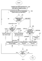
FIG. 8 is a flow chart of the multiple battery method of the present invention. Referring now to FIG. 8, in step 800 the multiple battery is connected to the electrical power system of a boat or vehicle, activating the electronics control module. In step 802 the electronics control module begins monitoring the parallel circuit for triggering events and waits for user input from the remote display panel. If in step 804 it is determined that no triggering event occurred and no user input was received, then control returns to step 802. If step 804 determines that user input was received, then step 806 determines if the user input was a starter battery button down input (a signal generated when the user presses the starter battery button on the remote display panel and is received in the electronics control module), auxiliary battery button down input (a signal generated when the user presses the auxiliary battery button on the remote display panel and is received in the electronics control module), or additional battery button down input (a signal generated when the user presses the additional battery button on the remote display panel and is received in the electronics control module).
If starter battery button down input was received in step 806, then in step 808 the electronics control module checks the charge status of the starter battery and returns a signal indicating that status to the starter battery section of the remote display panel, activating the appropriate indicator. If auxiliary battery button down input was received in step 806, then in step 810 the electronics control module checks the charge status of the auxiliary battery and returns a signal indicating that status to the auxiliary battery section of the remote display panel, activating the appropriate indicator. Similarly, if additional battery button down input was received in step 806, then in step 812 the electronics control module checks the charge status of the additional battery and returns a signal indicating that status to the additional battery section of the remote display panel, activating the appropriate indicator. After any of steps 808, 810, or 812, control then passes to step 822.
If step 804 determines that a triggering event was detected, then step 814 determines if the triggering event was a start event, an engine running event, or a recharge event. If a start event was detected in step 814, then in step 816 the electronics control module sends an on signal to a switch that connects the starter battery to the parallel circuit. If an engine running event was detected step 814, then in step 818 the electronics control module sends an off signal to a switch that disconnects the starter battery from the parallel circuit. Similarly, if a recharge event was detected in step 814, then in step 820 the electronics control module optimizes the recharging of the starter battery, the auxiliary battery, or the additional battery. After any of steps 816, 818, or 820, control then passes to step 822.
Step 822 determines if the battery is still connected to the electrical loads. If yes, control returns to step 802. If not, such as when storage mode switch 322 (FIG. 3) or storage mode switch 422 (FIG. 4) are pressed, the multiple battery method ends.
Having described a presently preferred embodiment of the present invention, it will be understood by those skilled in the art that many changes in construction and widely differing embodiments and applications of the invention will suggest themselves without departing from the scope of the present invention, as defined in the claims. The disclosures and the description herein are intended to be illustrative and are not in any sense limiting of the invention, defined in scope by the following claims.

Claims (6)

We claim:
1. A multiple battery method for a vehicle comprising:
(a) monitoring a circuit having an electrical load with an electronics control module;
(b) detecting a start event, an engine running event, a recharge event or user input in said circuit with said electronics control module;
(c) when a start event is detected, connecting a starter battery to the electrical load; when an engine running event is detected, disconnecting the starter battery and connecting an auxiliary battery to the electrical load; and when a recharge event is detected optimizing the recharging of the starter battery and auxiliary battery with the electronics control module; and
(d) when a user input is detected, checking and displaying a charge status of the first or second battery.
2. A multiple battery system comprising:
a starter battery and an auxiliary battery switchably connected to a parallel circuit, the circuit being configured for connection to an electrical load;
an electronics control module that monitors the circuit for start events and charge status requests, the control module connecting the starter battery to the circuit when a start event is detected and generating signals indicative of the starter and auxiliary battery charge status when a charge status request is detected; and
a display for showing the charge status of the starter and auxiliary batteries.
3. A multiple battery system as claimed in claim 2, wherein the electronics control module also monitors the circuit to determine when the batteries need recharging and, when charging current is available, initiates a recharge process that decreases the charging current as the batteries charge back up.
4. A multiple battery system as claimed in claim 3, and further comprising one or more additional batteries switchably connected in parallel to the starter battery and auxiliary battery.
5. A multiple battery system as claimed in claim 4, and further comprising a remote display panel for displaying the battery charge status.
6. A multiple battery system as claimed in claim 5, and further comprising a storage mode switch for disconnecting all batteries from the circuit.
US09/566,766 2000-05-08 2000-05-08 Multiple battery system and method Expired - Fee Related US6545445B1 (en)

Priority Applications (6)

Application Number Priority Date Filing Date Title
US09/566,766 US6545445B1 (en) 2000-05-08 2000-05-08 Multiple battery system and method
AU2001273576A AU2001273576A1 (en) 2000-05-08 2001-05-08 Multiple battery system and method
EP01952861A EP1297601A4 (en) 2000-05-08 2001-05-08 Multiple battery system and method
JP2001582854A JP2003533159A (en) 2000-05-08 2001-05-08 Multiple battery system and method
PCT/US2001/040698 WO2001086737A2 (en) 2000-05-08 2001-05-08 Multiple battery system and method
NO20025374A NO20025374L (en) 2000-05-08 2002-11-08 Multi-battery system and method

Applications Claiming Priority (1)

Application Number Priority Date Filing Date Title
US09/566,766 US6545445B1 (en) 2000-05-08 2000-05-08 Multiple battery system and method

Publications (1)

Publication Number Publication Date
US6545445B1 true US6545445B1 (en) 2003-04-08

Family

ID=24264289

Family Applications (1)

Application Number Title Priority Date Filing Date
US09/566,766 Expired - Fee Related US6545445B1 (en) 2000-05-08 2000-05-08 Multiple battery system and method

Country Status (6)

Country Link
US (1) US6545445B1 (en)
EP (1) EP1297601A4 (en)
JP (1) JP2003533159A (en)
AU (1) AU2001273576A1 (en)
NO (1) NO20025374L (en)
WO (1) WO2001086737A2 (en)

Cited By (33)

* Cited by examiner, † Cited by third party
Publication number Priority date Publication date Assignee Title
US20030052649A1 (en) * 2001-07-11 2003-03-20 Webasto Vehicle Systems International Gmbh Electrical accessory device controlling system for a motor vehicle and process for operation thereof
US20050035741A1 (en) * 2003-08-11 2005-02-17 David Elder Multiple battery management system, auxiliary battery attachment system, and network controlled multiple battery system
US20050035740A1 (en) * 2003-08-11 2005-02-17 Reserve Power Cell, Llc Multiple battery system and network controlled multiple battery system
US20050130712A1 (en) * 2003-12-16 2005-06-16 Saghbini Michael G. [Mobile communication system powered by multiple batteries]
US7009350B1 (en) * 2004-02-13 2006-03-07 Great Systems, Inc. Energy collection and storage system
US20060103352A1 (en) * 2004-11-18 2006-05-18 Jones Carl E Staggered backup battery charging system
US20060192528A1 (en) * 2003-12-03 2006-08-31 Borje Maleus Method and device for managing batteries of a battery system
US20060244421A1 (en) * 2005-04-14 2006-11-02 Kailas Narendran Method and apparatus of extracting residual charge from energy storage device
US7165641B2 (en) * 2003-04-01 2007-01-23 Shimano, Inc. Bicycle power supply with discharge function
US20070188129A1 (en) * 2006-01-20 2007-08-16 Kochan John R Jr Pump Control with Multiple Rechargeable Battery Docking Stations
US20070195711A1 (en) * 2006-02-22 2007-08-23 Terrel Morris Automated cable identification and verification system
US20070229032A1 (en) * 2006-07-14 2007-10-04 David Elder Battery monitoring, warranty, and performance tracking system
US20080019068A1 (en) * 2002-05-06 2008-01-24 Reynolds Gregory A Current protection apparatus and method
US20080019067A1 (en) * 2002-05-06 2008-01-24 Reynolds Gregory A Current protection apparatus and method
US20090174362A1 (en) * 2008-01-03 2009-07-09 F.D. Richardson Enterprises, Inc. Doing Business As Richardson Jumpstarters Method and apparatus for providing supplemental power to an engine
US20090218988A1 (en) * 2008-01-03 2009-09-03 Richardson Francis D Method and apparatus for providing supplemental power to an engine
US20090309540A1 (en) * 2005-03-30 2009-12-17 David Elder Method of operating a networl with a programmable battery and programming same
US20100271006A1 (en) * 2009-04-28 2010-10-28 Darby Group Inc. Start test electronic device and system and method of use thereof
US20110031046A1 (en) * 2008-04-21 2011-02-10 International Truck Intellectual Property Company, Multiple battery system of a motor vehicle
WO2012048478A1 (en) * 2010-10-12 2012-04-19 皆盈绿电池股份有限公司 Battery module
WO2012060766A1 (en) * 2010-11-01 2012-05-10 Scania Cv Ab Activation device and activation method for a dual-battery system
US20130154543A1 (en) * 2008-01-03 2013-06-20 Francis D. Richardson Method and apparatus for providing supplemental power to an engine
CN101544196B (en) * 2008-03-27 2013-07-17 福特环球技术公司 Dual battery vehicle electrical systems
US8519563B2 (en) 2008-02-04 2013-08-27 Scania Cv Ab (Publ) Electrical system for a motor vehicle and method for control of a starter motor and a battery isolator in such an electrical system
US8749193B1 (en) 2013-05-10 2014-06-10 Inpower Llc Battery protection circuit for multiple battery power supply and charging system
US20160236693A1 (en) * 2016-04-21 2016-08-18 Caterpillar Inc. Electric power supply system for machine
US9490662B2 (en) 2012-10-19 2016-11-08 Sun Medical Technology Research Corporation Power supply switching circuit and artificial heart system
US9672400B2 (en) * 2014-07-08 2017-06-06 Aila Technologies Inc. Imaging and peripheral enhancements for mobile devices
WO2018151665A1 (en) * 2017-02-16 2018-08-23 Razer (Asia-Pacific) Pte. Ltd. Power supply circuits, wearable devices and methods for providing power supply to a wearable device
WO2020043682A1 (en) * 2018-08-28 2020-03-05 Renault S.A.S Electrical circuit and motor vehicle comprising such a circuit
US20210380018A1 (en) * 2018-07-23 2021-12-09 Aulton New Energy Automotive Technology Group Battery Replacement Device and Control Method Therefor
US11549477B1 (en) 2022-07-29 2023-01-10 Ford Global Technologies, Llc Split charge battery start assist
US11764594B2 (en) * 2018-12-17 2023-09-19 Seiko Epson Corporation Electronic device, battery condition display method, and printing apparatus

Families Citing this family (6)

* Cited by examiner, † Cited by third party
Publication number Priority date Publication date Assignee Title
JP2004112900A (en) * 2002-09-18 2004-04-08 Nissan Motor Co Ltd Power generation controller for vehicle
FR2848736B1 (en) * 2002-12-17 2005-03-18 Peugeot Citroen Automobiles Sa POWER SUPPLY SYSTEM OF AT LEAST ONE LOAD
KR100969529B1 (en) * 2009-02-02 2010-07-12 (주) 엔네비솔루션 Apparatus for portable auxiliary power supply for automobile
JP6409635B2 (en) * 2015-03-17 2018-10-24 日立化成株式会社 Power storage system
FR3036862B1 (en) * 2015-06-01 2018-12-07 Sam Outillage SAFETY DEVICE AND METHOD FOR STARTER DEVICES ("BOOSTERS") OF MOTOR VEHICLES REQUIRING AN ELECTRIC STARTING OR STARTING POWER SOURCE
FR3098165B1 (en) * 2019-07-02 2021-10-15 Renault Sas electrical circuit and motor vehicle comprising such a circuit

Citations (3)

* Cited by examiner, † Cited by third party
Publication number Priority date Publication date Assignee Title
US5963010A (en) * 1996-10-31 1999-10-05 Hitachi, Ltd. Battery controller for controlling batteries of different kinds and including battery monitoring means for calculating remaining operation time and an information processing apparatus including such battery controller
US6229279B1 (en) * 1998-09-17 2001-05-08 Volkswagen Ag Dual battery system
US6275001B1 (en) * 1998-09-17 2001-08-14 Volkswagen Ag Dual-battery system

Family Cites Families (6)

* Cited by examiner, † Cited by third party
Publication number Priority date Publication date Assignee Title
US5397991A (en) * 1988-07-13 1995-03-14 Electronic Development Inc. Multi-battery charging system for reduced fuel consumption and emissions in automotive vehicles
US5488283A (en) * 1993-09-28 1996-01-30 Globe-Union, Inc. Vehicle battery system providing battery back-up and opportunity charging
GB9612932D0 (en) * 1995-06-22 1996-08-21 Glorywin Int Group Ltd Battery controller
FR2749814B1 (en) * 1996-06-14 1998-07-31 Renault ELECTRIC POWER SUPPLY DEVICE FOR A MOTOR VEHICLE
EP0753925A3 (en) * 1995-07-13 1997-07-02 Renault Electrical supply device for a motor vehicle and methods for control of such a device
DE19813369B4 (en) * 1998-03-26 2006-11-23 Robert Bosch Gmbh Device for power supply in a motor vehicle

Patent Citations (3)

* Cited by examiner, † Cited by third party
Publication number Priority date Publication date Assignee Title
US5963010A (en) * 1996-10-31 1999-10-05 Hitachi, Ltd. Battery controller for controlling batteries of different kinds and including battery monitoring means for calculating remaining operation time and an information processing apparatus including such battery controller
US6229279B1 (en) * 1998-09-17 2001-05-08 Volkswagen Ag Dual battery system
US6275001B1 (en) * 1998-09-17 2001-08-14 Volkswagen Ag Dual-battery system

Cited By (77)

* Cited by examiner, † Cited by third party
Publication number Priority date Publication date Assignee Title
US6762513B2 (en) * 2001-07-11 2004-07-13 Webasto Thermosysteme International Gmbh Electrical accessory device controlling system for a motor vehicle and process for operation thereof
US20030052649A1 (en) * 2001-07-11 2003-03-20 Webasto Vehicle Systems International Gmbh Electrical accessory device controlling system for a motor vehicle and process for operation thereof
US7672104B2 (en) 2002-05-06 2010-03-02 Cyber Switching, Inc. Current protection apparatus and method
US7630186B2 (en) * 2002-05-06 2009-12-08 Cyber Switching, Inc. Current protection apparatus and method
US20080019067A1 (en) * 2002-05-06 2008-01-24 Reynolds Gregory A Current protection apparatus and method
US20080019068A1 (en) * 2002-05-06 2008-01-24 Reynolds Gregory A Current protection apparatus and method
US7165641B2 (en) * 2003-04-01 2007-01-23 Shimano, Inc. Bicycle power supply with discharge function
US20100055546A1 (en) * 2003-08-11 2010-03-04 David Elder Multiple battery system
US20080111427A1 (en) * 2003-08-11 2008-05-15 Reserve Power Cell, Llc Auxiliary battery attachment apparatus for use in a multiple battery system that reliably supplies electrical energy to an electrical system
US20050035737A1 (en) * 2003-08-11 2005-02-17 Whodathought Holdings, Inc. [Multiple Battery System and Auxiliary Battery Attachment System]
US8120364B2 (en) 2003-08-11 2012-02-21 Reserve Power Cell, Llc Stand alone battery monitoring system with alert
US20080315686A1 (en) * 2003-08-11 2008-12-25 David Elder System and method of detecting a battery fault
US20100076706A1 (en) * 2003-08-11 2010-03-25 David Elder Stand alone battery monitoring system with alert
US7839117B2 (en) * 2003-08-11 2010-11-23 Reserve Power Cell, Llc System and method of detecting a battery fault
US7834583B2 (en) * 2003-08-11 2010-11-16 Reserve Power Cell, Llc Remotely controlled multiple battery system
US20080315837A1 (en) * 2003-08-11 2008-12-25 David Elder Remotely controlled multiple battery system
US7675261B2 (en) 2003-08-11 2010-03-09 Reserve Power Cell, Llc Auxiliary battery attachment apparatus for use in a multiple battery system that reliably supplies electrical energy to an electrical system
US20050035741A1 (en) * 2003-08-11 2005-02-17 David Elder Multiple battery management system, auxiliary battery attachment system, and network controlled multiple battery system
US7427865B2 (en) 2003-08-11 2008-09-23 Reserve Power Cell, Llc Method for detecting a discharge condition fault in an electrical system of a vehicle or piece of machinery
US7339347B2 (en) * 2003-08-11 2008-03-04 Reserve Power Cell, Llc Apparatus and method for reliably supplying electrical energy to an electrical system
US20050035740A1 (en) * 2003-08-11 2005-02-17 Reserve Power Cell, Llc Multiple battery system and network controlled multiple battery system
US7679314B2 (en) 2003-08-11 2010-03-16 Reserve Power Cell, Llc Multiple battery system for reliably supplying electrical energy to an electrical system
US20080111557A1 (en) * 2003-08-11 2008-05-15 Reserve Power Cell, Llc Method for detecting a discharge condition fault in an electrical system of a vehicle or piece of machinery
US7567057B2 (en) 2003-08-11 2009-07-28 Reserve Power Cell, Llc Multiple battery management system, auxiliary battery attachment system, and network controlled multiple battery system
US20080111426A1 (en) * 2003-08-11 2008-05-15 Reserve Power Cell, Llc Multiple battery system for reliably supplying electrical energy to an electrical system
US7388349B2 (en) * 2003-08-11 2008-06-17 Reserve Power Cell, Llc Multiple battery switching method and apparatus
US7638974B2 (en) * 2003-12-03 2009-12-29 Creator Teknisk Utveckling Ab Method and device for managing batteries of a battery system
US20060192528A1 (en) * 2003-12-03 2006-08-31 Borje Maleus Method and device for managing batteries of a battery system
US20050130712A1 (en) * 2003-12-16 2005-06-16 Saghbini Michael G. [Mobile communication system powered by multiple batteries]
US7020500B2 (en) * 2003-12-16 2006-03-28 Michael Gabriel Saghbini Mobile communication system powered by multiple batteries
US7205732B1 (en) * 2004-02-13 2007-04-17 Great Systems, Inc. Energy collection and storage system
US7009350B1 (en) * 2004-02-13 2006-03-07 Great Systems, Inc. Energy collection and storage system
US7345455B2 (en) 2004-11-18 2008-03-18 International Business Machines Corporation Staggered backup battery charging system
US7605566B2 (en) 2004-11-18 2009-10-20 International Business Machines Corporation Staggered backup battery charging system
US20060103352A1 (en) * 2004-11-18 2006-05-18 Jones Carl E Staggered backup battery charging system
US20070236185A1 (en) * 2004-11-18 2007-10-11 International Business Machines Corporation Staggered Backup Battery Charging System
US20080094033A1 (en) * 2004-11-18 2008-04-24 Jones Carl E Staggered Backup Battery Charging System
US7646172B2 (en) 2004-11-18 2010-01-12 International Business Machines Corporation Staggered backup battery charging system
US20090309540A1 (en) * 2005-03-30 2009-12-17 David Elder Method of operating a networl with a programmable battery and programming same
US20060244421A1 (en) * 2005-04-14 2006-11-02 Kailas Narendran Method and apparatus of extracting residual charge from energy storage device
US7612529B2 (en) * 2006-01-20 2009-11-03 Metropolitan Industries, Inc. Pump control with multiple rechargeable battery docking stations
US20070188129A1 (en) * 2006-01-20 2007-08-16 Kochan John R Jr Pump Control with Multiple Rechargeable Battery Docking Stations
US8488472B2 (en) * 2006-02-22 2013-07-16 Hewlett-Packard Development Company, L.P. Automated cable identification and verification system
CN103873295A (en) * 2006-02-22 2014-06-18 惠普开发有限公司 Automated cable identification and verification system
US20070195711A1 (en) * 2006-02-22 2007-08-23 Terrel Morris Automated cable identification and verification system
US8013611B2 (en) 2006-07-14 2011-09-06 Reserve Power Cell, Llc Vehicle battery product and battery monitoring system
US20070229032A1 (en) * 2006-07-14 2007-10-04 David Elder Battery monitoring, warranty, and performance tracking system
US20130154543A1 (en) * 2008-01-03 2013-06-20 Francis D. Richardson Method and apparatus for providing supplemental power to an engine
US9662991B2 (en) * 2008-01-03 2017-05-30 F.D. Richardson Enterprises, Inc. Method and apparatus for providing supplemental power to an engine
US20160082854A1 (en) * 2008-01-03 2016-03-24 F.D. Richardson Enterprises, Inc. Dba Richardson Jumpstarters Method and apparatus for providing supplemental power to an engine
US9263907B2 (en) * 2008-01-03 2016-02-16 F.D. Richardson Enterprises, Inc. Method and apparatus for providing supplemental power to an engine
US20090218988A1 (en) * 2008-01-03 2009-09-03 Richardson Francis D Method and apparatus for providing supplemental power to an engine
US20090174362A1 (en) * 2008-01-03 2009-07-09 F.D. Richardson Enterprises, Inc. Doing Business As Richardson Jumpstarters Method and apparatus for providing supplemental power to an engine
US8493021B2 (en) * 2008-01-03 2013-07-23 F. D. Richardson Entereprises, Inc. Method and apparatus for providing supplemental power to an engine
US8519563B2 (en) 2008-02-04 2013-08-27 Scania Cv Ab (Publ) Electrical system for a motor vehicle and method for control of a starter motor and a battery isolator in such an electrical system
CN101544196B (en) * 2008-03-27 2013-07-17 福特环球技术公司 Dual battery vehicle electrical systems
US8381852B2 (en) 2008-04-21 2013-02-26 International Truck Intellectual Property Company, Llc Multiple battery system of a motor vehicle
US20110031046A1 (en) * 2008-04-21 2011-02-10 International Truck Intellectual Property Company, Multiple battery system of a motor vehicle
US20100271006A1 (en) * 2009-04-28 2010-10-28 Darby Group Inc. Start test electronic device and system and method of use thereof
US8675321B2 (en) * 2009-04-28 2014-03-18 Darby Group Inc. Start test electronic device and system and method of use thereof
WO2012048478A1 (en) * 2010-10-12 2012-04-19 皆盈绿电池股份有限公司 Battery module
CN102447274A (en) * 2010-10-12 2012-05-09 皆盈绿电池股份有限公司 Battery module
EP2635799A1 (en) * 2010-11-01 2013-09-11 Scania CV AB Activation device and activation method for a dual-battery system
CN103201502A (en) * 2010-11-01 2013-07-10 斯堪尼亚商用车有限公司 Activation device and activation method for a dual-battery system
EP2635799A4 (en) * 2010-11-01 2014-09-24 Scania Cv Ab Activation device and activation method for a dual-battery system
WO2012060766A1 (en) * 2010-11-01 2012-05-10 Scania Cv Ab Activation device and activation method for a dual-battery system
US9490662B2 (en) 2012-10-19 2016-11-08 Sun Medical Technology Research Corporation Power supply switching circuit and artificial heart system
US8749193B1 (en) 2013-05-10 2014-06-10 Inpower Llc Battery protection circuit for multiple battery power supply and charging system
US9672400B2 (en) * 2014-07-08 2017-06-06 Aila Technologies Inc. Imaging and peripheral enhancements for mobile devices
US20160236693A1 (en) * 2016-04-21 2016-08-18 Caterpillar Inc. Electric power supply system for machine
WO2018151665A1 (en) * 2017-02-16 2018-08-23 Razer (Asia-Pacific) Pte. Ltd. Power supply circuits, wearable devices and methods for providing power supply to a wearable device
US10901480B2 (en) 2017-02-16 2021-01-26 Razer (Asia-Pacific) Pte. Ltd. Power supply circuits, wearable devices and methods for providing power supply to a wearable device
US20210380018A1 (en) * 2018-07-23 2021-12-09 Aulton New Energy Automotive Technology Group Battery Replacement Device and Control Method Therefor
WO2020043682A1 (en) * 2018-08-28 2020-03-05 Renault S.A.S Electrical circuit and motor vehicle comprising such a circuit
FR3085322A1 (en) * 2018-08-28 2020-03-06 Renault S.A.S. ELECTRICAL CIRCUIT, AND MOTOR VEHICLE COMPRISING SUCH A CIRCUIT
US11764594B2 (en) * 2018-12-17 2023-09-19 Seiko Epson Corporation Electronic device, battery condition display method, and printing apparatus
US11549477B1 (en) 2022-07-29 2023-01-10 Ford Global Technologies, Llc Split charge battery start assist

Also Published As

Publication number Publication date
WO2001086737A2 (en) 2001-11-15
AU2001273576A1 (en) 2001-11-20
NO20025374D0 (en) 2002-11-08
EP1297601A4 (en) 2005-03-23
JP2003533159A (en) 2003-11-05
EP1297601A2 (en) 2003-04-02
NO20025374L (en) 2003-01-07
WO2001086737A3 (en) 2002-01-31

Similar Documents

Publication Publication Date Title
US6545445B1 (en) Multiple battery system and method
US6452361B2 (en) Battery system
JP4003170B2 (en) Auxiliary function device for automobile and driving method thereof
US10998757B2 (en) Smartphone interfaced automotive smart battery with self boosting capability
US20100301800A1 (en) Multi-purpose battery jump starter and reconditioner
CA2799488A1 (en) System and method for electrical energy switching and control in a vehicle
US9194357B2 (en) Method for jump starting a vehicle
KR101933653B1 (en) Power management system for camping car
US11591996B2 (en) Emergency start
CN109120030B (en) Wireless charger and electronic equipment forgetting reminding method
JP2001352690A (en) Power supply circuit for vehicle, and dc-dc converter circuit used for the vehicle
CN211606187U (en) Vehicle-mounted electronic equipment power-down protection circuit and automobile
JP2022172283A (en) On-vehicle starting power source
JP3830126B2 (en) Power supply device for vehicle remote control
JPH11289687A (en) Device driven by power adapter and secondary battery
JPH03118772A (en) On-vehicle inverter for oa equipment
US20200124014A1 (en) Capacitive Car Jump Starter
US5777455A (en) Switch for a battery charging system
CN218678480U (en) Vehicle emergency start exclusive package
KR102594946B1 (en) Smart battery power management module for supplying power to multimedia and smart device of vehicles
CN109149704B (en) Wireless charger and electronic equipment forgetting reminding method
CN214492663U (en) Vehicle-mounted refrigerator
JP4261734B2 (en) Digital camera and power supply control method thereof
CN211684697U (en) Multifunctional vehicle charging anti-walking protection device
KR100233295B1 (en) Battery charging monitoring device for a vehicle

Legal Events

Date Code Title Description
AS Assignment

Owner name: BOULDER TECHNOLOGIES CORPORATION, COLORADO

Free format text: ASSIGNMENT OF ASSIGNORS INTEREST;ASSIGNORS:MCDERMOTT, JOSEPH J.;WAGNER, JAMES W.;JOHNSON RICHARD T.;AND OTHERS;REEL/FRAME:012144/0504;SIGNING DATES FROM 20001206 TO 20010828

AS Assignment

Owner name: GP BATTERIES INTERNATIONAL, LTD., CALIFORNIA

Free format text: ASSIGNMENT OF ASSIGNORS INTEREST;ASSIGNOR:BOLDER TECHNOLOGIES CORPORATION;REEL/FRAME:012569/0800

Effective date: 20011214

FPAY Fee payment

Year of fee payment: 4

REMI Maintenance fee reminder mailed
LAPS Lapse for failure to pay maintenance fees
STCH Information on status: patent discontinuation

Free format text: PATENT EXPIRED DUE TO NONPAYMENT OF MAINTENANCE FEES UNDER 37 CFR 1.362

FP Lapsed due to failure to pay maintenance fee

Effective date: 20110408