US6575939B1 - Device for automatic injection of a dose of medicinal product - Google Patents
Device for automatic injection of a dose of medicinal product Download PDFInfo
- Publication number
- US6575939B1 US6575939B1 US09/601,473 US60147300A US6575939B1 US 6575939 B1 US6575939 B1 US 6575939B1 US 60147300 A US60147300 A US 60147300A US 6575939 B1 US6575939 B1 US 6575939B1
- Authority
- US
- United States
- Prior art keywords
- casing
- collar
- piston rod
- rear part
- supporting
- Prior art date
- Legal status (The legal status is an assumption and is not a legal conclusion. Google has not performed a legal analysis and makes no representation as to the accuracy of the status listed.)
- Expired - Lifetime
Links
Images


Classifications
-
- A—HUMAN NECESSITIES
- A61—MEDICAL OR VETERINARY SCIENCE; HYGIENE
- A61M—DEVICES FOR INTRODUCING MEDIA INTO, OR ONTO, THE BODY; DEVICES FOR TRANSDUCING BODY MEDIA OR FOR TAKING MEDIA FROM THE BODY; DEVICES FOR PRODUCING OR ENDING SLEEP OR STUPOR
- A61M5/00—Devices for bringing media into the body in a subcutaneous, intra-vascular or intramuscular way; Accessories therefor, e.g. filling or cleaning devices, arm-rests
- A61M5/178—Syringes
- A61M5/20—Automatic syringes, e.g. with automatically actuated piston rod, with automatic needle injection, filling automatically
- A61M5/2033—Spring-loaded one-shot injectors with or without automatic needle insertion
-
- A—HUMAN NECESSITIES
- A61—MEDICAL OR VETERINARY SCIENCE; HYGIENE
- A61M—DEVICES FOR INTRODUCING MEDIA INTO, OR ONTO, THE BODY; DEVICES FOR TRANSDUCING BODY MEDIA OR FOR TAKING MEDIA FROM THE BODY; DEVICES FOR PRODUCING OR ENDING SLEEP OR STUPOR
- A61M5/00—Devices for bringing media into the body in a subcutaneous, intra-vascular or intramuscular way; Accessories therefor, e.g. filling or cleaning devices, arm-rests
- A61M5/178—Syringes
- A61M5/31—Details
- A61M5/32—Needles; Details of needles pertaining to their connection with syringe or hub; Accessories for bringing the needle into, or holding the needle on, the body; Devices for protection of needles
- A61M5/3205—Apparatus for removing or disposing of used needles or syringes, e.g. containers; Means for protection against accidental injuries from used needles
- A61M5/321—Means for protection against accidental injuries by used needles
- A61M5/3243—Means for protection against accidental injuries by used needles being axially-extensible, e.g. protective sleeves coaxially slidable on the syringe barrel
- A61M5/326—Fully automatic sleeve extension, i.e. in which triggering of the sleeve does not require a deliberate action by the user
-
- A—HUMAN NECESSITIES
- A61—MEDICAL OR VETERINARY SCIENCE; HYGIENE
- A61M—DEVICES FOR INTRODUCING MEDIA INTO, OR ONTO, THE BODY; DEVICES FOR TRANSDUCING BODY MEDIA OR FOR TAKING MEDIA FROM THE BODY; DEVICES FOR PRODUCING OR ENDING SLEEP OR STUPOR
- A61M5/00—Devices for bringing media into the body in a subcutaneous, intra-vascular or intramuscular way; Accessories therefor, e.g. filling or cleaning devices, arm-rests
- A61M5/178—Syringes
- A61M5/20—Automatic syringes, e.g. with automatically actuated piston rod, with automatic needle injection, filling automatically
- A61M2005/2006—Having specific accessories
- A61M2005/2013—Having specific accessories triggering of discharging means by contact of injector with patient body
-
- A—HUMAN NECESSITIES
- A61—MEDICAL OR VETERINARY SCIENCE; HYGIENE
- A61M—DEVICES FOR INTRODUCING MEDIA INTO, OR ONTO, THE BODY; DEVICES FOR TRANSDUCING BODY MEDIA OR FOR TAKING MEDIA FROM THE BODY; DEVICES FOR PRODUCING OR ENDING SLEEP OR STUPOR
- A61M5/00—Devices for bringing media into the body in a subcutaneous, intra-vascular or intramuscular way; Accessories therefor, e.g. filling or cleaning devices, arm-rests
- A61M5/178—Syringes
- A61M5/20—Automatic syringes, e.g. with automatically actuated piston rod, with automatic needle injection, filling automatically
- A61M2005/206—With automatic needle insertion
-
- A—HUMAN NECESSITIES
- A61—MEDICAL OR VETERINARY SCIENCE; HYGIENE
- A61M—DEVICES FOR INTRODUCING MEDIA INTO, OR ONTO, THE BODY; DEVICES FOR TRANSDUCING BODY MEDIA OR FOR TAKING MEDIA FROM THE BODY; DEVICES FOR PRODUCING OR ENDING SLEEP OR STUPOR
- A61M5/00—Devices for bringing media into the body in a subcutaneous, intra-vascular or intramuscular way; Accessories therefor, e.g. filling or cleaning devices, arm-rests
- A61M5/178—Syringes
- A61M5/20—Automatic syringes, e.g. with automatically actuated piston rod, with automatic needle injection, filling automatically
- A61M2005/2073—Automatic syringes, e.g. with automatically actuated piston rod, with automatic needle injection, filling automatically preventing premature release, e.g. by making use of a safety lock
- A61M2005/208—Release is possible only when device is pushed against the skin, e.g. using a trigger which is blocked or inactive when the device is not pushed against the skin
-
- A—HUMAN NECESSITIES
- A61—MEDICAL OR VETERINARY SCIENCE; HYGIENE
- A61M—DEVICES FOR INTRODUCING MEDIA INTO, OR ONTO, THE BODY; DEVICES FOR TRANSDUCING BODY MEDIA OR FOR TAKING MEDIA FROM THE BODY; DEVICES FOR PRODUCING OR ENDING SLEEP OR STUPOR
- A61M5/00—Devices for bringing media into the body in a subcutaneous, intra-vascular or intramuscular way; Accessories therefor, e.g. filling or cleaning devices, arm-rests
- A61M5/178—Syringes
- A61M5/31—Details
- A61M2005/3103—Leak prevention means for distal end of syringes, i.e. syringe end for mounting a needle
- A61M2005/3104—Caps for syringes without needle
-
- A—HUMAN NECESSITIES
- A61—MEDICAL OR VETERINARY SCIENCE; HYGIENE
- A61M—DEVICES FOR INTRODUCING MEDIA INTO, OR ONTO, THE BODY; DEVICES FOR TRANSDUCING BODY MEDIA OR FOR TAKING MEDIA FROM THE BODY; DEVICES FOR PRODUCING OR ENDING SLEEP OR STUPOR
- A61M5/00—Devices for bringing media into the body in a subcutaneous, intra-vascular or intramuscular way; Accessories therefor, e.g. filling or cleaning devices, arm-rests
- A61M5/178—Syringes
- A61M5/31—Details
- A61M2005/3103—Leak prevention means for distal end of syringes, i.e. syringe end for mounting a needle
- A61M2005/3107—Leak prevention means for distal end of syringes, i.e. syringe end for mounting a needle for needles
- A61M2005/3109—Caps sealing the needle bore by use of, e.g. air-hardening adhesive, elastomer or epoxy resin
-
- A—HUMAN NECESSITIES
- A61—MEDICAL OR VETERINARY SCIENCE; HYGIENE
- A61M—DEVICES FOR INTRODUCING MEDIA INTO, OR ONTO, THE BODY; DEVICES FOR TRANSDUCING BODY MEDIA OR FOR TAKING MEDIA FROM THE BODY; DEVICES FOR PRODUCING OR ENDING SLEEP OR STUPOR
- A61M2205/00—General characteristics of the apparatus
- A61M2205/58—Means for facilitating use, e.g. by people with impaired vision
- A61M2205/583—Means for facilitating use, e.g. by people with impaired vision by visual feedback
-
- A—HUMAN NECESSITIES
- A61—MEDICAL OR VETERINARY SCIENCE; HYGIENE
- A61M—DEVICES FOR INTRODUCING MEDIA INTO, OR ONTO, THE BODY; DEVICES FOR TRANSDUCING BODY MEDIA OR FOR TAKING MEDIA FROM THE BODY; DEVICES FOR PRODUCING OR ENDING SLEEP OR STUPOR
- A61M5/00—Devices for bringing media into the body in a subcutaneous, intra-vascular or intramuscular way; Accessories therefor, e.g. filling or cleaning devices, arm-rests
- A61M5/178—Syringes
- A61M5/31—Details
- A61M5/32—Needles; Details of needles pertaining to their connection with syringe or hub; Accessories for bringing the needle into, or holding the needle on, the body; Devices for protection of needles
- A61M5/3202—Devices for protection of the needle before use, e.g. caps
Definitions
- the invention concerns a device for automatically injecting a dose of a medicinal product.
- a number of injection devices exist at the present time enabling an inexperienced patient to self-administer a dose of a medicinal product without having to force the needle into himself or herself and actuate the piston of the syringe.
- the tendency consists of producing injection devices such as that described in patent EP 516 473, for single use including a propulsion spring designed to inject the medicinal product, and a propulsion spring designed to push the syringe back automatically into the casing after injection.
- a propulsion spring designed to inject the medicinal product
- a propulsion spring designed to push the syringe back automatically into the casing after injection.
- a long narrow casing having a front wall pierced by an orifice, and formed of two parts, a front part and a rear part, fitted one into the other and capable of sliding longitudinally in relation to each other over a short traverse so as to be able to undergo a relative movement between two positions: a retracted, so called rest position, of the rear part with respect to the front part obtained naturally in the absence of an external force exerted on the said parts, and a forward, so-called injection position, of the rear part with respect to the front part obtained by means of a longitudinal force exerted on the said rear part,
- a syringe disposed in the casing and including a syringe body housing a piston, provided with a finger rest ring and carrying a needle,
- a propulsion spring extending between the means for supporting the collar of the piston rod and the bottom of the rear part of the casing
- a return propulsion spring with a force less than that of the propulsion spring disposed around the syringe body so as to be compressed by the finger rest ring of the said syringe body when the latter is moved to its forward position.
- the present invention aims to overcome this disadvantage and its object is to provide an automatic injection device designed so as to enable a strictly defined dose of a medicinal product to be injected systematically.
- Another object of the invention is to provide an injection device with a simplified design and therefore with a cost price compatible with that of a single-use device.
- Another object of the invention is to provide an injection device which can be used with pre-filled syringes of the traditional type.
- the invention concerns a device for automatically injecting a dose of a medicinal product of the type described in patent application WO 94/21316.
- this injection device is characterized in that:
- a cage with a form adapted so as to slide inside the guide tube, and to house the piston rod and the collar thereof, the said cage including towards one of its ends, the so-called rear end, an internal device for locking the collar of the piston rod capable of deforming radially and, towards its other forward end, a front wall for stopping the propulsion spring and for contacting the means of locking in translation the said supporting means in the retracted position of the latter,
- the said guide tube and cage being adapted so that, in the forward position of the supporting means, the device for locking the collar of the piston rod remains imprisoned in the guide tube in the forward relative position of the parts of the casing, and is freed in the retracted relative position of the said parts of the casing.
- injection is carried out by applying first of all and in a conventional manner the forward end of the casing against the skin.
- a pressure exerted on the rear part of the casing then permits the triggering of the propulsion spring and therefore the injection of the product.
- the patient has a visual indication of the end of the traverse which informs him or her that the entire dose has been injected. He or she may then relax the pressure on the rear part of the casing, a relaxation which will enable is this rear part to retract and consequently allow the syringe to return into the casing under the action of the return propulsion spring.
- Such an injection device which firstly includes a casing in two parts of which the relative movement enables the tolerances in variations in the lengths of the syringes to be absorbed and enables injection and subsequent return of the syringe inside the casing to be triggered, and secondly includes a visual indication of the end of injection, thus makes it possible to deliver systematically the entire product enclosed in the syringe and moreover constitutes a single-use device eliminating any risk of pricking before and after use.
- the guide tube and the cage preferably have dimensions adapted so as to house the piston rod and the finger rest ring of the syringe body, the said cage including an internal device for stopping the finger rest ring of the syringe body in the retracted position of the said cage, and a front wall provided with an opening for permitting relative movement of this cage and the syringe body in the forward position of the latter.
- this internal device for stopping the finger rest ring of the syringe body advantageously makes it possible to prevent the said syringe body from being entrained forwards when the protective end of the needle is withdrawn. Indeed, this entrainment, observed with current devices, and which tends to compress the return propulsion spring, results in difficulties for the user who, observing a resistance resulting from this compression, may hesitate to exert forces aimed at overcoming this resistance.
- this injection device is adapted so as to be used with a traditional syringe of which the finger rest ring has a truncated annular form and includes two diametrically opposed flats.
- the cage consists of a stirrup having two longitudinal legs arranged so that each comes into contact with a flat of the finger rest ring.
- Such a stirrup has the advantage of constituting an element for locking the syringe body in rotation, having a small overall transverse size, which combined with the arrangement of the propulsion spring in an annular space situated around the said stirrup, results in an injection device being obtained with a reduced overall size.
- the internal device for locking the collar of the piston rod consists of transverse grooves provided facing the legs of the stirrup,
- this stirrup includes a ring in the rear extension of which the longitudinal legs extend, the internal device for stopping the finger rest ring of the syringe body including at least one inclined tongue extending longitudinally inside the said ring.
- the rear part of the casing has the form externally of a sleeve with a generally cylindrical form
- the front part of the casing has dimensions adapted so as to be housed over most of its length inside the rear part of the said casing
- guiding devices are adapted so as to enable the rear part of the casing to move over a short traverse along the front part of the said casing.
- This arrangement of the front and rear parts of the casing makes it possible to obtain a casing which is perfectly rigid in flexion and which is therefore very safe in operation by the user.
- the means for locking in translation the means for supporting the collar of the piston rod comprise:
- an internal axial device for stopping the deformable stop device provided inside the rear part of the casing,
- a trigger provided in the peripheral wall of the rear part of the casing so that it can deform and free the, device for stopping the supporting means, in the retracted position of the latter,
- This arrangement makes it possible to provide a guarantee against any accidental triggering of the injection since the latter requires, first of all, a pressure to be exerted on the casing, and then secondly, a pressure to be applied to the trigger so as to retract the deformable device for stopping the supporting means.
- the trigger has a longitudinal T-shape, the opening having a corresponding shape and being provided so as to have a transverse arm offset longitudinally from the transverse bar of the trigger in the retracted relative position of the parts of the casing.
- the injection device includes a cap with a form adapted so as to close off the front end section of the front part of the casing and to butt up against the rear part of the said causing in the retracted position of the latter.
- Such a cap apart from its conventional protective function, makes it possible to block the front and rear parts of the casing relatively in translation, before use, in the retracted position of the said parts.
- the front part of the casing advantageously incorporates an internal conduit for guiding the syringe body extending over a portion of a length of the-said front part from the front wall of the latter, the said conduit having a shoulder for stopping the said syringe body in its forward position.
- the cap also preferably includes claws extending longitudinally inside the said cap and disposed so as to lodge in the inner conduit for guiding the syringe body, the said claws being adapted so as to hook over an end piece protecting the needle of the syringe.
- This arrangement makes it possible to withdraw automatically the end piece protecting the needle in a conventional manner, when the cap is removed.
- the rear part of the casing and the cap have contact faces profiled in the shape of a cam so that the said cap can be removed by a rotational movement of the latter.
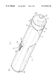
- FIG. 1 is a perspective view of an auto-injection device according to.the invention.
- FIG. 2 is a longitudinal section through an axial plane of the rear part of the casing of this auto-injection device
- FIG. 3 is a longitudinal section through an axial plane B of this rear part of the casing
- FIG. 4 is a longitudinal section through the axial plane A of the front part of the casing of this auto-injection device
- FIG. 5 is a longitudinal view from above of this front part of the casing
- FIG. 6 is a perspective view of the stirrup for supporting the piston rod of the syringe
- FIG. 7 is a longitudinal section through the axial plane A of the cap of this auto-injection device.
- FIGS. 8 to 13 are longitudinal sections through the axial plane A of the auto-injection device according to the invention, illustrating successive steps in the operation of this device,
- FIGS. 14 and 15 are partial diagrammatic perspective views representing the auto-injection device in the retracted and forward positions respectively of the rear section, the front section of the said auto-injection device being shown in dotted lines,
- FIG. 16 is a transverse section through a plane C of this auto-injection device.
- the auto-injection device according to the invention is of the single-use type and is adapted so as to enable the patient to administer to himself or herself a dose of medicinal liquid enclosed in a pre-filled syringe 1 of a traditional type, such as for example one made of glass, and including in a conventional manner:
- a rear finger rest ring 4 having a truncated annular form, i.e. possessing, as shown in FIG. 16, two diametrically opposed flats such as 4 a,
- a piston rod 7 formed over its greater length of a rod 7 a with a cruciform cross section extended by a rear tubular section 7 b pierced by an axial blind bore 8 emerging in the region of the rear collar 9 with a generally square shape.
- This auto-injection device includes, first of all, a casing with a generally cylindrical outer form composed of two parts, a said rear part 10 and a front part 11 , one fitted inside the other so as to be able to slide longitudinally one inside the other over a short traverse of the order of a few millimeters.
- the rear part 10 of the casing consists, so that it can be made by injecting a plastic material, of two elements 12 , 13 adapted so as to be assembled after manufacture to form an assembly in one piece.
- the first of these elements 12 has the form of a sleeve of generally cylindrical form provided with a front end 14 profiled in the form of a cam.
- This sleeve 12 is, in addition, provided with a “trigger” delimited by a slot 17 provided in its peripheral wall, and adapted so as to pivot longitudinally and to retract partially inside the said sleeve under the effect of manual pressure.
- This trigger 15 has longitudinally the shape of a T of which the longitudinal bar 15 a is oriented in the direction of the rear end of the sleeve 12 and has, seen in plan, a rectangular shape adapted so as to be pressed by a finger, so that the transverse bar 15 b retracts inside the sleeve 12 when such pressure is applied.
- This trigger 15 has, finally, a corrugated upper face provided with transverse ribs such as 16 projecting with respect to the peripheral wall of the sleeve 12 .
- the sleeve 12 also includes a transverse inner rib 18 in the form of a circular sector, provided opposite the transverse bar 15 b of the trigger 15 and separated therefrom by the transverse portion of the slot 17 .
- This sleeve 12 finally includes an oblong opening 19 with a large longitudinal axis provided in the front quarter section of the said sleeve, in the region of a generating line diametrically opposite the trigger 15 .
- the second element 13 of the rear section 10 consists of a tube 13 with a generally cylindrical shape, closed in the region of its rear end by an end piece 13 a with a shape adapted so as to fit inside the first element 12 .
- This end piece 13 a moreover includes a centering pin 20 projecting with respect to its front wall, so as to extend axially into the sleeve 12 , over a portion of the length of the latter.
- This tube 13 has an external diameter less than the internal diameter of the first element 12 adapted so as to delimit an annular volume 21 inside the latter.
- the tube 13 additionally includes internal longitudinal ribs such as 22 distributed around the axis of the tube, extending from the end piece 13 a and interrupted at a distance from the front end of the said tube so as to form an axial stop shoulder inside the latter.
- This tube 13 finally includes two diametrically opposed cutaways such as 23 which have a trapezoidal shape when seen in plan.
- the front part 11 of the casing includes a cylindrical case 24 with an external diameter adapted so as to be housed inside the rear part 10 of the said casing.
- this case 24 is provided with an external pin 25 with a shape adapted so as to be housed inside the oblong opening 19 of the rear part 10 .
- This external pin 25 has moreover a diameter less than the length of the oblong opening 19 , adapted so as to allow the front part 11 to slide longitudinally over a short traverse of the order of a few millimeters inside the rear part 10 of the casing.
- the case 24 is extended in the region of its front end by a tubular nozzle 26 with a generally frustoconical shape, pierced axially with a frustoconical bore 27 b having a cross section which decreases from the end face of the said tubular nozzle.
- This frustoconical bore 27 b is moreover provided in the extension of a cylindrical conduit 27 for guiding the syringe body, extending axially inside the cylindrical case and separated from the said frustoconical bore by an axial stop shoulder 27 c of the said syringe body.
- the cylindrical case 24 is moreover pierced next to the tubular nozzle 26 with two diametrically opposed radial openings 28 , 29 .
- the front part 11 of the casing moreover includes a rear longitudinal leg 30 extending into the extension of the cylindrical case 24 , and consisting of a portion of the peripheral wall of the said cylindrical case delimiting a circular sector with an angle at the top of the order of 60°.
- This longitudinal leg 30 first of all includes an axial opening 31 provided from its rear end, with a width greater than that of the longitudinal bar 15 a of the trigger 15 and less than the length of the transverse bar 15 b of the said trigger.
- This longitudinal leg 30 additionally includes two cutaways such as 32 arranged facing each other so as to emerge into the opening 31 substantially halfway along the latter and so as to delimit a transverse slot with a length greater than that of the transverse bar 15 b of the trigger 15 , separated from the rear end of the said longitudinal leg by a region of the wall in the form of a notch 33 .
- This longitudinal leg 30 finally includes a longitudinal groove 34 provided axially in the extension of the opening 31 .
- the auto-injection device additionally includes a stirrup 35 shown in FIG. 6 for supporting and entraining the piston rod 7 of the syringe 1 .
- This stirrup 35 first of all has two parallel longitudinal legs 36 , 37 separated by a distance and having a cross section adapted so as to be able to slide in the tube 13 of the rear part 10 .
- This stirrup 35 additionally includes an annular ring 38 made in one piece with the longitudinal legs 36 , 37 and inside which are provided the front end sections of the said legs.
- this annular ring 38 has a cutaway with a deformable tongue 39 extending inside it, secured to the said ring in the region of its rear end.
- this ring 39 has two inclined tongues such as 40 , offset by 90° with respect to the longitudinal legs 36 , 37 and oriented in the direction of the rear end of the stirrup 35 .
- Each longitudinal leg 36 , 37 of the stirrup 35 additionally includes an internal transverse rib such as 41 provided in the region of the rear end of the said leg and, at a short distance from the said rib, an axial button 42 projecting with respect to the inner face of this leg 36 , 37 .
- the auto-injection device also includes a cap 43 adapted so as to cover the end section of the front part 11 of the casing and including to this end a cylindrical section 44 extended by a frustoconical nozzle 47 , with dimensions matching those of the cylindrical case 24 and the tubular nozzle 26 .
- the rear end 45 of the cylindrical section 44 of this cap 43 has, moreover, the form of a cam matching that of the sleeve 12 of the rear part 10 of the casing, adapted so as to enable the said cap to be removed by a rotational movement imparted to the latter in one or other rotational direction.
- the cap 43 also includes external serrations such as 46 provided on the cylindrical section 44 and forming a knurling for manually gripping the said cap.
- the cap 43 finally includes an axial front opening 47 a provided in the frustoconical nozzle 47 and, extending into this cap 43 from this front opening 47 a , three longitudinal claws 48 arranged uniformly around the axis of the said cap.
- claws 48 provided with ends in the form of hooks 49 are provided so as to be retightened when the cap 43 is put in place on the front part 11 of the casing, on account of the frustoconical shape of the bore 27 b of the said front part, and so as to hook onto the end piece 45 for protecting the needle 3 of the syringe 1 with a view to enabling the latter to be removed.
- the auto-injection device finally includes two propulsion springs 50 , 51 :
- an injection propulsion spring 50 housed in the annular space 21 of the rear part 10 of the casing so as to extend between the front wall of the end piece 13 a and the ring 38 of the stirrup 35 ,
- a return propulsion spring 51 with a force less than that of the propulsion spring 50 disposed about the syringe 1 so as to extend between the rear end of the cylindrical conduit 27 and the finger rest ring 4 of the said syringe.
- the injection propulsion spring 50 is held compressed between the front wall 13 a of the tube 13 and the ring 38 of the stirrup 35 ,
- the syringe 1 is entirely housed inside the casing, the end of the protective end piece 5 being situated recessed from the end of the nozzle 26 ,
- the rear part 10 of the casing is situated in a “retracted” position with respect to the front part 11 of the said casing, a position in which, as shown in FIG. 14, the transverse bar 15 b of the trigger 15 becomes positioned facing the notches 33 , preventing the said trigger from being actuated.
- the first operation consists of withdrawing the cap 43 and simultaneously the end piece 5 protecting the needle 3 .
- This withdrawal is obtained by turning the cap 43 in one direction or another, a rotation during which the cam-shaped profiles 14 , 45 lead to the production of an axial movement of the said cap, so that the said withdrawal is similar to a simple unscrewing operation.
- the syringe 1 does not undergo any translational movement on account of the fact that the finger rest ring 4 is butted up against the tongues 40 of the stirrup 35 , so that no compression of the return propulsion spring 51 takes place.
- the following operation consists of applying the nozzle 26 of the casing against the skin and of exerting a longitudinal pressure on the rear part 10 of the said casing. As shown in FIG. 9, this operation causes the rear part 10 of the casing to move forwards relative to the front part 11 , a movement during which relative guiding of the said parts is ensured by the pin 25 housed in the opening 19 .
- the transverse bar 15 b of the trigger 15 is positioned facing the cutaways 32 , so that the said trigger can be actuated.
- injection is then obtained by actuating the trigger 15 which leads to a deformation of the tongue 39 and freeing of the stirrup 35 which, under the effect of the propulsion spring 50 :
- the ring 38 of the stirrup 35 becomes positioned opposite the openings 28 , 29 of the casing so that the patient can see this ring 38 and can therefore be assured of the complete emptying of the syringe 1 .
- the syringe 1 is then propelled inside the casing under the action of the return propulsion spring 51 until the finger rest ring 4 is butted up against the end of the ribs 22 .
- the injection device may then be discarded without any risk of subsequent pricking, on account of the fact that, on the one hand, the needle 3 is situated clearly withdrawn from the end of the nozzle 26 of the casing, and on the other hand, that the said device cannot be reactivated.
Abstract
Description
Claims (12)
Applications Claiming Priority (3)
| Application Number | Priority Date | Filing Date | Title |
|---|---|---|---|
| FR9801298 | 1998-02-04 | ||
| FR9801298A FR2774294B1 (en) | 1998-02-04 | 1998-02-04 | DEVICE FOR AUTOMATICALLY INJECTING A DOSE OF MEDICINAL PRODUCT |
| PCT/FR1998/002809 WO1999039759A1 (en) | 1998-02-04 | 1998-12-21 | Device for automatic injection of a dose of medicinal product |
Publications (1)
| Publication Number | Publication Date |
|---|---|
| US6575939B1 true US6575939B1 (en) | 2003-06-10 |
Family
ID=9522589
Family Applications (1)
| Application Number | Title | Priority Date | Filing Date |
|---|---|---|---|
| US09/601,473 Expired - Lifetime US6575939B1 (en) | 1998-02-04 | 1998-12-21 | Device for automatic injection of a dose of medicinal product |
Country Status (8)
| Country | Link |
|---|---|
| US (1) | US6575939B1 (en) |
| EP (1) | EP1053037B1 (en) |
| AT (1) | ATE227593T1 (en) |
| AU (1) | AU1767999A (en) |
| DE (1) | DE69809471T2 (en) |
| ES (1) | ES2188036T3 (en) |
| FR (1) | FR2774294B1 (en) |
| WO (1) | WO1999039759A1 (en) |
Cited By (124)
| Publication number | Priority date | Publication date | Assignee | Title |
|---|---|---|---|---|
| US20030100862A1 (en) * | 2001-07-19 | 2003-05-29 | Edwards Evan T. | Medical injector |
| US20040133159A1 (en) * | 2003-01-07 | 2004-07-08 | Haider M. Ishaq | Disposable injection device |
| WO2005025637A2 (en) | 2003-09-17 | 2005-03-24 | Dali Medical Devices Ltd. | Automatic needle device |
| US20050085776A1 (en) * | 2003-10-16 | 2005-04-21 | Edgar Hommann | Injection device for administering a fluid product |
| US20050203466A1 (en) * | 2003-12-18 | 2005-09-15 | Edgar Hommann | Auto-injector with active agent container latching |
| US20060224124A1 (en) * | 2003-09-11 | 2006-10-05 | Benjamin Scherer | Administering device for an injectable product with a release lock |
| US20060229570A1 (en) * | 2002-09-11 | 2006-10-12 | Becton, Dickinson And Company | Injector device with force lock-out and injection rate limiting mechanisms |
| WO2006106294A1 (en) | 2005-04-06 | 2006-10-12 | Cilag Ag International | Injection device |
| WO2006106292A1 (en) * | 2005-04-06 | 2006-10-12 | Cilag Ag International | An injection device (angled trigger) |
| WO2006106293A1 (en) | 2005-04-06 | 2006-10-12 | Cilag Gmbh International | Injection device (modified trigger) |
| EP1755706A1 (en) | 2004-05-28 | 2007-02-28 | Cilag GmbH International | Injection device |
| US20070088268A1 (en) * | 2004-11-22 | 2007-04-19 | Edwards Eric S | Devices systems and methods for medicament delivery |
| US20080009807A1 (en) * | 2003-09-11 | 2008-01-10 | Edgar Hommann | Administration device with an insertion mechanism and a delivery mechanism |
| US20080312590A1 (en) * | 2004-05-28 | 2008-12-18 | Tim Barrow-Williams | Injection Device |
| US20090024112A1 (en) * | 2005-02-01 | 2009-01-22 | Edwards Eric S | Medical injector with compliance tracking and monitoring |
| US20090054838A1 (en) * | 2004-05-28 | 2009-02-26 | Cilag Ag International | Injection device |
| WO2009063030A1 (en) * | 2007-11-14 | 2009-05-22 | Shl Group Ab | Automatic injection device with actively triggered syringe withdrawal |
| WO2009062508A1 (en) * | 2007-11-12 | 2009-05-22 | Bang & Olufsen Medicom A/S | Auto injector with a rotatable release shaft |
| US20090227896A1 (en) * | 2008-03-07 | 2009-09-10 | Becton, Dickinson And Company | Flashback Blood Collection Needle |
| US20090234297A1 (en) * | 2005-04-06 | 2009-09-17 | Douglas Ivan Jennings | Injection device |
| US7648483B2 (en) | 2004-11-22 | 2010-01-19 | Intelliject, Inc. | Devices, systems and methods for medicament delivery |
| US7648482B2 (en) | 2004-11-22 | 2010-01-19 | Intelliject, Inc. | Devices, systems, and methods for medicament delivery |
| US7731686B2 (en) | 2005-02-01 | 2010-06-08 | Intelliject, Inc. | Devices, systems and methods for medicament delivery |
| US20100160942A1 (en) * | 2008-12-18 | 2010-06-24 | Facet Technologies, Llc | Lancing device and lancet |
| US7749194B2 (en) | 2005-02-01 | 2010-07-06 | Intelliject, Inc. | Devices, systems, and methods for medicament delivery |
| US20100185178A1 (en) * | 2009-01-20 | 2010-07-22 | Robert Sharp | Injection device |
| US7901377B1 (en) | 2004-05-28 | 2011-03-08 | Cilag Gmbh International | Injection device |
| USD634426S1 (en) | 2010-04-08 | 2011-03-15 | Facet Technologies, Llc | Lancing device |
| US7947017B2 (en) | 2004-11-22 | 2011-05-24 | Intelliject, Inc. | Devices, systems and methods for medicament delivery |
| US20110166474A1 (en) * | 2007-03-07 | 2011-07-07 | Becton, Dickinson And Company | Safety Blood Collection Assembly with Indicator |
| US7985216B2 (en) | 2004-03-16 | 2011-07-26 | Dali Medical Devices Ltd. | Medicinal container engagement and automatic needle device |
| US20110196311A1 (en) * | 2007-08-10 | 2011-08-11 | Owen Mumford Limited | Injection devices |
| EP2364741A1 (en) * | 2010-03-09 | 2011-09-14 | Sanofi-Aventis Deutschland GmbH | Interlock mechanism for defining an operation sequence of an auto-injector |
| WO2011111006A2 (en) | 2010-03-10 | 2011-09-15 | Menarini International Operations Luxembourg S.A. | Device for the automatic injection of two doses of a medicament |
| US8128594B1 (en) * | 2010-11-03 | 2012-03-06 | Chang li-feng | Safety syringe |
| US8162887B2 (en) | 2004-06-23 | 2012-04-24 | Abbott Biotechnology Ltd. | Automatic injection devices |
| US8206360B2 (en) | 2005-02-01 | 2012-06-26 | Intelliject, Inc. | Devices, systems and methods for medicament delivery |
| US8231573B2 (en) | 2005-02-01 | 2012-07-31 | Intelliject, Inc. | Medicament delivery device having an electronic circuit system |
| US20120232491A1 (en) * | 2006-06-01 | 2012-09-13 | Douglas Ivan Jennings | Injection Device |
| US8277414B2 (en) | 2004-05-28 | 2012-10-02 | Cilag Gmbh International | Injection device |
| US8313464B2 (en) | 2004-05-28 | 2012-11-20 | Cilag Gmbh International | Injection device |
| US8313465B2 (en) | 2004-05-28 | 2012-11-20 | Cilag Gmbh International | Injection device |
| US8343110B2 (en) | 2004-05-28 | 2013-01-01 | Cilag Gmbh International | Injection device |
| US8361026B2 (en) | 2005-02-01 | 2013-01-29 | Intelliject, Inc. | Apparatus and methods for self-administration of vaccines and other medicaments |
| US8366669B2 (en) | 2005-04-06 | 2013-02-05 | Cilag Gmbh International | Injection device |
| US8376998B2 (en) | 2003-09-17 | 2013-02-19 | Elcam Medical Agricultural Cooperative Association Ltd. | Automatic injection device |
| ITFI20110194A1 (en) * | 2011-09-08 | 2013-03-09 | Menarini Int Operations Lu Sa | MEDICINE DOSES SELF-INJECTION DEVICE |
| ITFI20110193A1 (en) * | 2011-09-08 | 2013-03-09 | Menarini Int Operations Lu Sa | DEVICE FOR AUTOMATIC INJECTION OF TWO DRUG DOSES |
| US8425460B2 (en) | 2005-09-01 | 2013-04-23 | Owen Mumford Limited | Needle shroud assembly |
| US20130123711A1 (en) * | 2011-11-07 | 2013-05-16 | Safety Syringes, Inc. | Contact trigger release needle guard |
| US20130138048A1 (en) * | 2010-03-09 | 2013-05-30 | Sanofi-Aventis Deutschland Gmbh | Autoinjector |
| AU2011256890B2 (en) * | 2005-04-06 | 2013-09-05 | Cilag Gmbh International | Injection device (modified trigger) |
| US20130324934A1 (en) * | 2011-01-11 | 2013-12-05 | Shl Group Ab | Medicament Delivery Device |
| US8622973B2 (en) | 2008-07-28 | 2014-01-07 | Intelliject, Inc. | Simulated medicament delivery device configured to produce an audible output |
| US8627816B2 (en) | 2011-02-28 | 2014-01-14 | Intelliject, Inc. | Medicament delivery device for administration of opioid antagonists including formulations for naloxone |
| US8636704B2 (en) | 2009-04-29 | 2014-01-28 | Abbvie Biotechnology Ltd | Automatic injection device |
| US20140039407A1 (en) * | 2012-06-20 | 2014-02-06 | Safety Syringes, Inc. | Contact trigger release needle guard with elastic spring |
| US8679061B2 (en) | 2006-06-30 | 2014-03-25 | Abbvie Biotechnology Ltd | Automatic injection device |
| US8708968B2 (en) | 2011-01-24 | 2014-04-29 | Abbvie Biotechnology Ltd. | Removal of needle shields from syringes and automatic injection devices |
| US8758301B2 (en) | 2009-12-15 | 2014-06-24 | Abbvie Biotechnology Ltd | Firing button for automatic injection device |
| US8834419B2 (en) | 2008-06-19 | 2014-09-16 | Cilag Gmbh International | Reusable auto-injector |
| US8845594B2 (en) | 2008-06-19 | 2014-09-30 | Cilag Gmbh International | Auto-injector with filling means |
| US8888713B2 (en) | 2007-03-07 | 2014-11-18 | Becton, Dickinson And Company | Safety blood collection assembly with indicator |
| US8932252B2 (en) | 2005-02-01 | 2015-01-13 | Kaleo, Inc. | Medical injector simulation device |
| US8939958B2 (en) | 2008-06-19 | 2015-01-27 | Cilag Gmbh International | Fluid transfer assembly for a syringe |
| US8939943B2 (en) | 2011-01-26 | 2015-01-27 | Kaleo, Inc. | Medicament delivery device for administration of opioid antagonists including formulations for naloxone |
| AU2012238194B2 (en) * | 2005-04-06 | 2015-03-26 | Cilag Gmbh International | Injection device |
| US9028453B2 (en) | 2008-06-19 | 2015-05-12 | Cilag Gmbh International | Reusable auto-injector |
| USD732161S1 (en) * | 2012-03-23 | 2015-06-16 | Terumo Kabushiki Kaisha | Intradermal injection device |
| US9072833B2 (en) | 2006-06-01 | 2015-07-07 | Cilag Gmbh International | Injection device |
| US9084849B2 (en) | 2011-01-26 | 2015-07-21 | Kaleo, Inc. | Medicament delivery devices for administration of a medicament within a prefilled syringe |
| USD736374S1 (en) * | 2013-06-21 | 2015-08-11 | Arkray, Inc. | Lancet |
| USD736375S1 (en) * | 2013-06-21 | 2015-08-11 | Arkray, Inc. | Lancet holder |
| EP2083887B2 (en) † | 2006-11-13 | 2015-09-30 | Cilag GmbH International | Injection device |
| US9167996B2 (en) | 2008-03-07 | 2015-10-27 | Becton, Dickinson And Company | Flashback blood collection needle |
| US9180244B2 (en) | 2010-04-21 | 2015-11-10 | Abbvie Biotechnology Ltd | Wearable automatic injection device for controlled delivery of therapeutic agents |
| US9265887B2 (en) | 2011-01-24 | 2016-02-23 | Abbvie Biotechnology Ltd. | Automatic injection devices having overmolded gripping surfaces |
| WO2016060908A1 (en) | 2014-10-12 | 2016-04-21 | Min Wei | Automatic injection device for multiple dosing |
| US9358346B2 (en) | 2005-08-30 | 2016-06-07 | Cilag Gmbh International | Needle assembly for a prefilled syringe system |
| US20160287787A1 (en) * | 2011-09-23 | 2016-10-06 | Sanofi-Aventis Deutschland Gmbh | Medicament Delivery Device and Actuation Mechanism for a Drug Delivery Device |
| USD768856S1 (en) * | 2015-02-05 | 2016-10-11 | Roche Diabetes Care, Inc. | Lancing device |
| US9517307B2 (en) | 2014-07-18 | 2016-12-13 | Kaleo, Inc. | Devices and methods for delivering opioid antagonists including formulations for naloxone |
| US9522235B2 (en) | 2012-05-22 | 2016-12-20 | Kaleo, Inc. | Devices and methods for delivering medicaments from a multi-chamber container |
| US9542826B2 (en) | 2012-12-27 | 2017-01-10 | Kaleo, Inc. | Devices, systems and methods for locating and interacting with medicament delivery systems |
| EP2255842B1 (en) | 2009-05-26 | 2017-05-03 | SHL Group AB | Needle cover assembly |
| US9649441B2 (en) | 2005-04-06 | 2017-05-16 | Cilag Gmbh International | Injection device (bayonet cap removal) |
| US9675757B2 (en) | 2004-05-28 | 2017-06-13 | Cilag Gmbh International | Injection device |
| US9675758B2 (en) * | 2004-05-28 | 2017-06-13 | Cilag Gmbh International | Injection device |
| US9682194B2 (en) | 2008-06-19 | 2017-06-20 | Cilag Gmbh International | Re-useable auto-injector with filling means |
| US9757520B2 (en) | 2006-06-01 | 2017-09-12 | Cilag Gmbh International | Injection device |
| US9770558B2 (en) | 2005-09-27 | 2017-09-26 | Cilag Gmbh International | Auto-injection device with needle protecting cap having outer and inner sleeves |
| US9844331B2 (en) | 2011-12-15 | 2017-12-19 | Facet Technologies, Llc | Latch mechanism for preventing lancet oscillation in a lancing device |
| USD824023S1 (en) * | 2016-08-30 | 2018-07-24 | Owen Mumford Limited | Injection device |
| US10085681B2 (en) | 2012-04-11 | 2018-10-02 | Facet Technologies, Llc | Lancing device with moving pivot depth adjust |
| US10332623B2 (en) | 2017-01-17 | 2019-06-25 | Kaleo, Inc. | Medicament delivery devices with wireless connectivity and event detection |
| USD861859S1 (en) * | 2016-09-07 | 2019-10-01 | Sanofi-Aventis Deutschland Gmbh | Injection device and cap for injection device |
| US10456069B2 (en) | 2012-04-12 | 2019-10-29 | Facet Technologies, Llc | Lancing device with side activated charge and eject mechanisms |
| US10576206B2 (en) | 2015-06-30 | 2020-03-03 | Kaleo, Inc. | Auto-injectors for administration of a medicament within a prefilled syringe |
| US10688244B2 (en) | 2016-12-23 | 2020-06-23 | Kaleo, Inc. | Medicament delivery device and methods for delivering drugs to infants and children |
| US10695495B2 (en) | 2015-03-24 | 2020-06-30 | Kaleo, Inc. | Devices and methods for delivering a lyophilized medicament |
| US10709849B2 (en) | 2013-06-11 | 2020-07-14 | Cilag Gmbh International | Guide for an injection device |
| US10737028B2 (en) | 2004-11-22 | 2020-08-11 | Kaleo, Inc. | Devices, systems and methods for medicament delivery |
| US10799646B2 (en) | 2013-06-11 | 2020-10-13 | Cilag Gmbh International | Injection device |
| US10806867B2 (en) | 2011-01-24 | 2020-10-20 | E3D Agricultural Cooperative Association Ltd. | Injector |
| US20200384209A1 (en) * | 2015-04-24 | 2020-12-10 | Shl Medical Ag | Drive mechanism |
| WO2021113041A1 (en) * | 2019-12-03 | 2021-06-10 | University Of Florida Research Foundation | Devices and methods for intravitreal injection of substances |
| US11058825B2 (en) | 2015-11-27 | 2021-07-13 | Sanofi-Aventis Deutschland Gmbh | Cap for an injection device |
| US11123492B2 (en) | 2013-06-11 | 2021-09-21 | Cilag Gmbh International | Injection device |
| WO2021188165A1 (en) * | 2020-03-20 | 2021-09-23 | Alexander Nikon | Auto-injector |
| US11167087B2 (en) | 2019-08-09 | 2021-11-09 | Kaleo, Inc. | Devices and methods for delivery of substances within a prefilled syringe |
| US11173255B2 (en) | 2013-06-11 | 2021-11-16 | Cilag Gmbh International | Injection device |
| US11590286B2 (en) | 2004-11-22 | 2023-02-28 | Kaleo, Inc. | Devices, systems and methods for medicament delivery |
| USD985116S1 (en) | 2021-03-10 | 2023-05-02 | Amgen Inc. | Handheld drug delivery device |
| USD985117S1 (en) | 2021-03-10 | 2023-05-02 | Amgen Inc. | Handheld drug delivery device |
| USD985118S1 (en) | 2021-03-10 | 2023-05-02 | Amgen Inc. | Handheld drug delivery device |
| USD985119S1 (en) | 2021-03-30 | 2023-05-02 | Amgen Inc. | Handheld drug delivery device |
| USD990668S1 (en) | 2020-11-05 | 2023-06-27 | Amgen Inc. | Handheld drug delivery device |
| USD992109S1 (en) | 2020-11-05 | 2023-07-11 | Amgen Inc. | Handheld drug delivery device |
| USD994111S1 (en) | 2008-05-12 | 2023-08-01 | Kaleo, Inc. | Medicament delivery device cover |
| USD1001272S1 (en) | 2016-04-28 | 2023-10-10 | Amgen Inc. | Autoinjector with removable cap |
| USD1004078S1 (en) | 2019-09-30 | 2023-11-07 | Amgen Inc. | Handheld drug delivery device |
| USD1010107S1 (en) | 2020-11-05 | 2024-01-02 | Amgen Inc. | Handheld drug delivery device |
| US11890459B2 (en) * | 2020-03-27 | 2024-02-06 | Medivena Sp. Z O.O. | Needle-based device with external safety cap and a needle guide element thereof |
| US11929160B2 (en) | 2018-07-16 | 2024-03-12 | Kaleo, Inc. | Medicament delivery devices with wireless connectivity and compliance detection |
Families Citing this family (4)
| Publication number | Priority date | Publication date | Assignee | Title |
|---|---|---|---|---|
| SE518981C2 (en) * | 2000-12-14 | 2002-12-17 | Shl Medical Ab | autoinjector |
| US7247151B2 (en) * | 2002-05-09 | 2007-07-24 | Adam Slawson | Injector with shielded needle |
| EP2129415B1 (en) | 2007-03-22 | 2018-10-24 | Tecpharma Licensing AG | Injection device with controlled needle retraction |
| DE102007013837A1 (en) * | 2007-03-22 | 2008-09-25 | Tecpharma Licensing Ag | Spring arrangement in an injection device |
Citations (11)
| Publication number | Priority date | Publication date | Assignee | Title |
|---|---|---|---|---|
| US3712301A (en) | 1971-01-11 | 1973-01-23 | Survival Technology | Gun type hypodermic injector with rapid cartridge displacement within holder |
| US3797489A (en) | 1972-02-10 | 1974-03-19 | Survival Technology | Hypodermic injection device with shock absorbing spring |
| FR2654938A1 (en) | 1989-11-28 | 1991-05-31 | Glaxo Group Ltd | ADMINISTRATION DEVICE. |
| EP0518416A1 (en) | 1991-06-13 | 1992-12-16 | Duphar International Research B.V | Injection device |
| EP0577448A1 (en) | 1992-06-04 | 1994-01-05 | Societe D'etudes Et Applications Techniques ( S.E.D.A.T.) | Automatic syringe driver |
| WO1994021316A1 (en) | 1993-03-24 | 1994-09-29 | Owen Mumford Limited | Improvements relating to injection devices |
| US5364362A (en) * | 1992-02-19 | 1994-11-15 | Henke-Sass, Wolf Gmbh | Front syringe attachment for hypodermic syringes for subcutaneous injection in veterinary medicine |
| WO1995035126A1 (en) | 1994-06-17 | 1995-12-28 | Safe-T-Limited | Hollow-needle drugs etc. applicators |
| EP0516473B1 (en) | 1991-05-30 | 1996-02-14 | Owen Mumford Limited | Automatic injection devices |
| US5709662A (en) * | 1996-08-23 | 1998-01-20 | Becton Dickinson France, S.A. | Cartridge for an injection device |
| US6210369B1 (en) * | 1997-12-16 | 2001-04-03 | Meridian Medical Technologies Inc. | Automatic injector |
-
1998
- 1998-02-04 FR FR9801298A patent/FR2774294B1/en not_active Expired - Fee Related
- 1998-12-21 DE DE69809471T patent/DE69809471T2/en not_active Expired - Lifetime
- 1998-12-21 US US09/601,473 patent/US6575939B1/en not_active Expired - Lifetime
- 1998-12-21 ES ES98962533T patent/ES2188036T3/en not_active Expired - Lifetime
- 1998-12-21 WO PCT/FR1998/002809 patent/WO1999039759A1/en active IP Right Grant
- 1998-12-21 AT AT98962533T patent/ATE227593T1/en not_active IP Right Cessation
- 1998-12-21 AU AU17679/99A patent/AU1767999A/en not_active Abandoned
- 1998-12-21 EP EP98962533A patent/EP1053037B1/en not_active Expired - Lifetime
Patent Citations (12)
| Publication number | Priority date | Publication date | Assignee | Title |
|---|---|---|---|---|
| US3712301A (en) | 1971-01-11 | 1973-01-23 | Survival Technology | Gun type hypodermic injector with rapid cartridge displacement within holder |
| US3797489A (en) | 1972-02-10 | 1974-03-19 | Survival Technology | Hypodermic injection device with shock absorbing spring |
| FR2654938A1 (en) | 1989-11-28 | 1991-05-31 | Glaxo Group Ltd | ADMINISTRATION DEVICE. |
| EP0516473B1 (en) | 1991-05-30 | 1996-02-14 | Owen Mumford Limited | Automatic injection devices |
| EP0518416A1 (en) | 1991-06-13 | 1992-12-16 | Duphar International Research B.V | Injection device |
| US5364362A (en) * | 1992-02-19 | 1994-11-15 | Henke-Sass, Wolf Gmbh | Front syringe attachment for hypodermic syringes for subcutaneous injection in veterinary medicine |
| EP0577448A1 (en) | 1992-06-04 | 1994-01-05 | Societe D'etudes Et Applications Techniques ( S.E.D.A.T.) | Automatic syringe driver |
| WO1994021316A1 (en) | 1993-03-24 | 1994-09-29 | Owen Mumford Limited | Improvements relating to injection devices |
| WO1995035126A1 (en) | 1994-06-17 | 1995-12-28 | Safe-T-Limited | Hollow-needle drugs etc. applicators |
| US5957897A (en) * | 1994-06-17 | 1999-09-28 | Safe-T-Limited | Hollow needle applicator for cartridged drugs |
| US5709662A (en) * | 1996-08-23 | 1998-01-20 | Becton Dickinson France, S.A. | Cartridge for an injection device |
| US6210369B1 (en) * | 1997-12-16 | 2001-04-03 | Meridian Medical Technologies Inc. | Automatic injector |
Cited By (316)
| Publication number | Priority date | Publication date | Assignee | Title |
|---|---|---|---|---|
| US20030100862A1 (en) * | 2001-07-19 | 2003-05-29 | Edwards Evan T. | Medical injector |
| US9486581B2 (en) | 2002-09-11 | 2016-11-08 | Becton, Dickinson And Company | Injector device with force lock-out and injection rate limiting mechanisms |
| US20060229570A1 (en) * | 2002-09-11 | 2006-10-12 | Becton, Dickinson And Company | Injector device with force lock-out and injection rate limiting mechanisms |
| US7905866B2 (en) | 2003-01-07 | 2011-03-15 | Becton, Dickinson And Company | Disposable injection device |
| US20040133159A1 (en) * | 2003-01-07 | 2004-07-08 | Haider M. Ishaq | Disposable injection device |
| US8157768B2 (en) | 2003-01-07 | 2012-04-17 | Becton Dickinson And Company | Disposable injection device |
| US20080021390A1 (en) * | 2003-01-07 | 2008-01-24 | Becton Dickinson And Company | Disposable injection device |
| US7252651B2 (en) | 2003-01-07 | 2007-08-07 | Becton, Dickinson And Company | Disposable injection device |
| US20110098641A1 (en) * | 2003-01-07 | 2011-04-28 | Becton, Dickinson And Company | Disposable injection device |
| US8603040B2 (en) | 2003-01-07 | 2013-12-10 | Becton, Dickinson And Company | Disposable injection device |
| US7749195B2 (en) * | 2003-09-11 | 2010-07-06 | Tecpharma Licensing Ag | Administration device with an insertion mechanism and a delivery mechanism |
| US20060224124A1 (en) * | 2003-09-11 | 2006-10-05 | Benjamin Scherer | Administering device for an injectable product with a release lock |
| US20080009807A1 (en) * | 2003-09-11 | 2008-01-10 | Edgar Hommann | Administration device with an insertion mechanism and a delivery mechanism |
| EP2650033A2 (en) | 2003-09-17 | 2013-10-16 | Elcam Medical Agricultural Cooperative Association Ltd. | Automatic injection device |
| US8376998B2 (en) | 2003-09-17 | 2013-02-19 | Elcam Medical Agricultural Cooperative Association Ltd. | Automatic injection device |
| US11623051B2 (en) | 2003-09-17 | 2023-04-11 | E3D Agricultural Cooperative Association Ltd. | Automatic injection device |
| WO2005025637A2 (en) | 2003-09-17 | 2005-03-24 | Dali Medical Devices Ltd. | Automatic needle device |
| US20050085776A1 (en) * | 2003-10-16 | 2005-04-21 | Edgar Hommann | Injection device for administering a fluid product |
| US8409149B2 (en) | 2003-12-18 | 2013-04-02 | Tecpharma Licensing Ag | Auto-injector with active agent container latching |
| US9427528B2 (en) | 2003-12-18 | 2016-08-30 | Tecpharma Licensing Ag | Auto-injector with active agent container latching |
| US9855392B2 (en) | 2003-12-18 | 2018-01-02 | Tecpharma Licensing Ag | Auto-injector with active agent container latching |
| US10973988B2 (en) | 2003-12-18 | 2021-04-13 | Ypsomed Ag | Auto-injector with active agent container latching |
| US11426529B2 (en) | 2003-12-18 | 2022-08-30 | Ypsomed Ag | Auto-injector with active agent container latching |
| US7357790B2 (en) | 2003-12-18 | 2008-04-15 | Tecpharma Licensing Ag | Auto-injector with active agent container latching |
| US8945049B2 (en) | 2003-12-18 | 2015-02-03 | Tecpharma Licensing Ag | Auto-injector with active agent container latching |
| US10960143B2 (en) | 2003-12-18 | 2021-03-30 | Ypsomed Ag | Auto-injector with active agent container latching |
| US20050203466A1 (en) * | 2003-12-18 | 2005-09-15 | Edgar Hommann | Auto-injector with active agent container latching |
| US20080015520A1 (en) * | 2003-12-18 | 2008-01-17 | Tecpharma Licensing Ag | Auto-injector with active agent container latching |
| DE102004060146C5 (en) * | 2003-12-18 | 2015-12-31 | Tecpharma Licensing Ag | Autoinjector with locking of the drug container |
| US10493213B2 (en) | 2003-12-18 | 2019-12-03 | Tecpharma Licensing Ag | Auto-injector with active agent container latching |
| US7985216B2 (en) | 2004-03-16 | 2011-07-26 | Dali Medical Devices Ltd. | Medicinal container engagement and automatic needle device |
| US8313465B2 (en) | 2004-05-28 | 2012-11-20 | Cilag Gmbh International | Injection device |
| US9675758B2 (en) * | 2004-05-28 | 2017-06-13 | Cilag Gmbh International | Injection device |
| US9675757B2 (en) | 2004-05-28 | 2017-06-13 | Cilag Gmbh International | Injection device |
| US8343110B2 (en) | 2004-05-28 | 2013-01-01 | Cilag Gmbh International | Injection device |
| US8277414B2 (en) | 2004-05-28 | 2012-10-02 | Cilag Gmbh International | Injection device |
| US20090054838A1 (en) * | 2004-05-28 | 2009-02-26 | Cilag Ag International | Injection device |
| US20080312590A1 (en) * | 2004-05-28 | 2008-12-18 | Tim Barrow-Williams | Injection Device |
| US7785292B2 (en) | 2004-05-28 | 2010-08-31 | Ethicon Endo-Surgery, Inc. | Injection device |
| NO338446B1 (en) * | 2004-05-28 | 2016-08-15 | Cilag Gmbh Int | injection device |
| US7901377B1 (en) | 2004-05-28 | 2011-03-08 | Cilag Gmbh International | Injection device |
| US9895493B2 (en) | 2004-05-28 | 2018-02-20 | Cilag Gmbh International | Injection device |
| EP1755706A1 (en) | 2004-05-28 | 2007-02-28 | Cilag GmbH International | Injection device |
| US8313464B2 (en) | 2004-05-28 | 2012-11-20 | Cilag Gmbh International | Injection device |
| US8313463B2 (en) | 2004-05-28 | 2012-11-20 | Cilag Gmbh International | Injection device |
| US9764090B2 (en) | 2004-06-23 | 2017-09-19 | Abbvie Biotechnology Ltd | Relating to automatic injection devices |
| US9017287B2 (en) | 2004-06-23 | 2015-04-28 | Abbvie Biotechnology Ltd | Automatic injection devices |
| US8668670B2 (en) | 2004-06-23 | 2014-03-11 | Abbvie Biotechnology Ltd | Automatic injection devices |
| US8162887B2 (en) | 2004-06-23 | 2012-04-24 | Abbott Biotechnology Ltd. | Automatic injection devices |
| US11590286B2 (en) | 2004-11-22 | 2023-02-28 | Kaleo, Inc. | Devices, systems and methods for medicament delivery |
| US10737028B2 (en) | 2004-11-22 | 2020-08-11 | Kaleo, Inc. | Devices, systems and methods for medicament delivery |
| US9833573B2 (en) | 2004-11-22 | 2017-12-05 | Kaleo, Inc. | Devices, systems and methods for medicament delivery |
| US7947017B2 (en) | 2004-11-22 | 2011-05-24 | Intelliject, Inc. | Devices, systems and methods for medicament delivery |
| US10314977B2 (en) | 2004-11-22 | 2019-06-11 | Kaleo, Inc. | Devices, systems and methods for medicament delivery |
| US8016788B2 (en) | 2004-11-22 | 2011-09-13 | Intelliject, Inc. | Devices, systems and methods for medicament delivery |
| US10335549B2 (en) | 2004-11-22 | 2019-07-02 | Kaleo, Inc. | Devices, systems and methods for medicament delivery |
| US7731690B2 (en) | 2004-11-22 | 2010-06-08 | Intelliject, Inc. | Devices, systems and methods for medicament delivery |
| US8425462B2 (en) | 2004-11-22 | 2013-04-23 | Intelliject, Inc. | Devices, systems, and methods for medicament delivery |
| US9737669B2 (en) | 2004-11-22 | 2017-08-22 | Kaleo, Inc. | Devices, systems and methods for medicament delivery |
| US7648482B2 (en) | 2004-11-22 | 2010-01-19 | Intelliject, Inc. | Devices, systems, and methods for medicament delivery |
| US7918823B2 (en) | 2004-11-22 | 2011-04-05 | Intelliject, Inc. | Devices, systems and methods for medicament delivery |
| US8105281B2 (en) | 2004-11-22 | 2012-01-31 | Intelliject, Inc. | Devices, systems and methods for medicament delivery |
| US7648483B2 (en) | 2004-11-22 | 2010-01-19 | Intelliject, Inc. | Devices, systems and methods for medicament delivery |
| US8920377B2 (en) | 2004-11-22 | 2014-12-30 | Kaleo, Inc. | Devices, systems and methods for medicament delivery |
| US8608698B2 (en) | 2004-11-22 | 2013-12-17 | Intelliject, Inc. | Devices, systems and methods for medicament delivery |
| US10071203B2 (en) | 2004-11-22 | 2018-09-11 | Kaleo, Inc. | Devices, systems and methods for medicament delivery |
| US8361029B2 (en) | 2004-11-22 | 2013-01-29 | Intelliject, Llc | Devices, systems and methods for medicament delivery |
| US9056170B2 (en) | 2004-11-22 | 2015-06-16 | Kaleo, Inc. | Devices, systems and methods for medicament delivery |
| US20070088268A1 (en) * | 2004-11-22 | 2007-04-19 | Edwards Eric S | Devices systems and methods for medicament delivery |
| US8313466B2 (en) | 2004-11-22 | 2012-11-20 | Intelliject, Inc. | Devices, systems and methods for medicament delivery |
| US9352091B2 (en) | 2004-11-22 | 2016-05-31 | Kaleo, Inc. | Devices, systems and methods for medicament delivery |
| US9149579B2 (en) | 2004-11-22 | 2015-10-06 | Kaleo, Inc. | Devices, systems and methods for medicament delivery |
| US10796604B2 (en) | 2005-02-01 | 2020-10-06 | Kaleo, Inc. | Medical injector simulation device and containers for storing delivery devices |
| US9259539B2 (en) | 2005-02-01 | 2016-02-16 | Kaleo, Inc. | Devices, systems and methods for medicament delivery |
| US8231573B2 (en) | 2005-02-01 | 2012-07-31 | Intelliject, Inc. | Medicament delivery device having an electronic circuit system |
| US8226610B2 (en) | 2005-02-01 | 2012-07-24 | Intelliject, Inc. | Medical injector with compliance tracking and monitoring |
| US8206360B2 (en) | 2005-02-01 | 2012-06-26 | Intelliject, Inc. | Devices, systems and methods for medicament delivery |
| US8932252B2 (en) | 2005-02-01 | 2015-01-13 | Kaleo, Inc. | Medical injector simulation device |
| US8926594B2 (en) | 2005-02-01 | 2015-01-06 | Kaleo, Inc. | Devices, systems and methods for medicament delivery |
| US8361026B2 (en) | 2005-02-01 | 2013-01-29 | Intelliject, Inc. | Apparatus and methods for self-administration of vaccines and other medicaments |
| US8172082B2 (en) | 2005-02-01 | 2012-05-08 | Intelliject, Inc. | Devices, systems and methods for medicament delivery |
| US9724471B2 (en) | 2005-02-01 | 2017-08-08 | Kaleo, Inc. | Devices, systems, and methods for medicament delivery |
| US10835673B2 (en) | 2005-02-01 | 2020-11-17 | Kaleo, Inc. | Devices, systems, and methods for medicament delivery |
| US8123719B2 (en) | 2005-02-01 | 2012-02-28 | Intelliject, Inc. | Devices, systems and methods for medicament delivery |
| US8920367B2 (en) | 2005-02-01 | 2014-12-30 | Kaleo, Inc. | Devices, systems and methods for medicament delivery |
| US9238108B2 (en) | 2005-02-01 | 2016-01-19 | Kaleo, Inc. | Medicament delivery device having an electronic circuit system |
| US8899987B2 (en) | 2005-02-01 | 2014-12-02 | Kaleo, Inc. | Simulated medicament delivery device having an electronic circuit system |
| US10076611B2 (en) | 2005-02-01 | 2018-09-18 | Kaleo, Inc. | Medicament delivery device having an electronic circuit system |
| US10918791B2 (en) | 2005-02-01 | 2021-02-16 | Kaleo, Inc. | Devices, systems and methods for medicament delivery |
| US9278177B2 (en) | 2005-02-01 | 2016-03-08 | Kaleo, Inc. | Medical injector with compliance tracking and monitoring |
| US7731686B2 (en) | 2005-02-01 | 2010-06-08 | Intelliject, Inc. | Devices, systems and methods for medicament delivery |
| US10960155B2 (en) | 2005-02-01 | 2021-03-30 | Kaleo, Inc. | Devices, systems and methods for medicament delivery |
| US9022980B2 (en) | 2005-02-01 | 2015-05-05 | Kaleo, Inc. | Medical injector simulation device |
| US9278182B2 (en) | 2005-02-01 | 2016-03-08 | Kaleo, Inc. | Devices, systems and methods for medicament delivery |
| US10105489B2 (en) | 2005-02-01 | 2018-10-23 | Kaleo, Inc. | Medical injector with compliance tracking and monitoring |
| US7749194B2 (en) | 2005-02-01 | 2010-07-06 | Intelliject, Inc. | Devices, systems, and methods for medicament delivery |
| US8544645B2 (en) | 2005-02-01 | 2013-10-01 | Intelliject, Inc. | Devices, systems and methods for medicament delivery |
| US20090024112A1 (en) * | 2005-02-01 | 2009-01-22 | Edwards Eric S | Medical injector with compliance tracking and monitoring |
| US10099023B2 (en) | 2005-02-01 | 2018-10-16 | Kaleo, Inc. | Devices, systems and methods for medicament delivery |
| US9327077B2 (en) | 2005-02-01 | 2016-05-03 | Kaleo, Inc. | Medical injector with compliance tracking and monitoring |
| US9805620B2 (en) | 2005-02-01 | 2017-10-31 | Kaleo, Inc. | Medical injector simulation device |
| US9867938B2 (en) | 2005-02-01 | 2018-01-16 | Kaleo, Inc. | Devices, systems and methods for medicament delivery |
| US8690827B2 (en) | 2005-02-01 | 2014-04-08 | Kaleo, Inc. | Devices, systems, and methods for medicament delivery |
| WO2006106293A1 (en) | 2005-04-06 | 2006-10-12 | Cilag Gmbh International | Injection device (modified trigger) |
| NO340162B1 (en) * | 2005-04-06 | 2017-03-20 | Cilag Gmbh Int | Injection device (modified trigger) |
| EA011742B1 (en) * | 2005-04-06 | 2009-06-30 | Цилаг Гмбх Интернэшнл | Injection device |
| JP2008534204A (en) * | 2005-04-06 | 2008-08-28 | シラグ・ゲーエムベーハー・インターナショナル | Injection device (tilt trigger) |
| KR101379668B1 (en) * | 2005-04-06 | 2014-04-01 | 칠락 게엠베하 인테르나티오날 | An injection device (angled trigger) |
| US9649441B2 (en) | 2005-04-06 | 2017-05-16 | Cilag Gmbh International | Injection device (bayonet cap removal) |
| CN101272817B (en) * | 2005-04-06 | 2011-05-04 | 西拉格国际有限公司 | An injection device with a pivoted trigger |
| EP2460550B2 (en) † | 2005-04-06 | 2018-10-10 | Cilag GmbH International | Injection device |
| CN101262898B (en) * | 2005-04-06 | 2010-12-08 | 西拉格国际有限公司 | Injection device |
| JP2008534205A (en) * | 2005-04-06 | 2008-08-28 | シラグ・ゲーエムベーハー・インターナショナル | Infusion device (modified trigger) |
| US8968236B2 (en) | 2005-04-06 | 2015-03-03 | Cilag Gmbh International | Injection device |
| WO2006106292A1 (en) * | 2005-04-06 | 2006-10-12 | Cilag Ag International | An injection device (angled trigger) |
| EA011805B1 (en) * | 2005-04-06 | 2009-06-30 | Цилаг Гмбх Интернэшнл | An injection device |
| AU2011256890B2 (en) * | 2005-04-06 | 2013-09-05 | Cilag Gmbh International | Injection device (modified trigger) |
| NO339250B1 (en) * | 2005-04-06 | 2016-11-21 | Cilag Gmbh Int | Injection device (modified trigger) |
| CN101287511B (en) * | 2005-04-06 | 2011-06-22 | 西拉格国际有限公司 | Injection device |
| WO2006106294A1 (en) | 2005-04-06 | 2006-10-12 | Cilag Ag International | Injection device |
| EA012075B1 (en) * | 2005-04-06 | 2009-08-28 | Цилаг Гмбх Интернэшнл | Injection device |
| EP2366415A1 (en) * | 2005-04-06 | 2011-09-21 | Cilag GmbH International | Injection device |
| US9731080B2 (en) * | 2005-04-06 | 2017-08-15 | Cilag Gmbh International | Injection device |
| AU2006231102B2 (en) * | 2005-04-06 | 2011-09-29 | Cilag Gmbh International | Injection device (modified trigger) |
| US20090234297A1 (en) * | 2005-04-06 | 2009-09-17 | Douglas Ivan Jennings | Injection device |
| US8366669B2 (en) | 2005-04-06 | 2013-02-05 | Cilag Gmbh International | Injection device |
| EP2460550A1 (en) | 2005-04-06 | 2012-06-06 | Cilag GmbH International | Injection device |
| US8317751B2 (en) | 2005-04-06 | 2012-11-27 | Cilag Gmbh International | Injection device |
| AU2012238194B2 (en) * | 2005-04-06 | 2015-03-26 | Cilag Gmbh International | Injection device |
| US9358346B2 (en) | 2005-08-30 | 2016-06-07 | Cilag Gmbh International | Needle assembly for a prefilled syringe system |
| US8425460B2 (en) | 2005-09-01 | 2013-04-23 | Owen Mumford Limited | Needle shroud assembly |
| EP1919540B1 (en) | 2005-09-01 | 2016-05-18 | Owen Mumford Limited | Needle shroud assembly |
| US9770558B2 (en) | 2005-09-27 | 2017-09-26 | Cilag Gmbh International | Auto-injection device with needle protecting cap having outer and inner sleeves |
| US9757520B2 (en) | 2006-06-01 | 2017-09-12 | Cilag Gmbh International | Injection device |
| US9072833B2 (en) | 2006-06-01 | 2015-07-07 | Cilag Gmbh International | Injection device |
| US20120232491A1 (en) * | 2006-06-01 | 2012-09-13 | Douglas Ivan Jennings | Injection Device |
| US9028451B2 (en) * | 2006-06-01 | 2015-05-12 | Cilag Gmbh International | Injection device |
| US8679061B2 (en) | 2006-06-30 | 2014-03-25 | Abbvie Biotechnology Ltd | Automatic injection device |
| US9486584B2 (en) | 2006-06-30 | 2016-11-08 | Abbvie Biotechnology Ltd. | Automatic injection device |
| EP2083887B2 (en) † | 2006-11-13 | 2015-09-30 | Cilag GmbH International | Injection device |
| US9555191B2 (en) | 2007-01-22 | 2017-01-31 | Kaleo, Inc. | Apparatus and methods for self-administration of vaccines and other medicaments |
| US10258735B2 (en) | 2007-02-05 | 2019-04-16 | Kaleo, Inc. | Apparatus and methods for self-administration of vaccines and other medicaments |
| US20170251966A1 (en) * | 2007-03-07 | 2017-09-07 | Becton, Dickinson And Company | Safety Blood Collection Assembly with Indicator |
| US11020033B2 (en) | 2007-03-07 | 2021-06-01 | Becton, Dickinson And Company | Safety blood collection assembly with indicator |
| US9687184B2 (en) * | 2007-03-07 | 2017-06-27 | Becton, Dickinson And Company | Safety blood collection assembly with indicator |
| US8888713B2 (en) | 2007-03-07 | 2014-11-18 | Becton, Dickinson And Company | Safety blood collection assembly with indicator |
| US10588558B2 (en) * | 2007-03-07 | 2020-03-17 | Becton, Dickinson And Company | Safety blood collection assembly with indicator |
| US10349880B2 (en) | 2007-03-07 | 2019-07-16 | Becton, Dickinson And Company | Safety blood collection assembly with indicator |
| US9271668B2 (en) * | 2007-03-07 | 2016-03-01 | Becton, Dickinson And Company | Safety blood collection assembly with indicator |
| US20110166476A1 (en) * | 2007-03-07 | 2011-07-07 | Becton, Dickinson And Company | Safety Blood Collection Assembly with Indicator |
| US9615783B2 (en) | 2007-03-07 | 2017-04-11 | Becton, Dickinson And Company | Safety blood collection assembly with indicator |
| US20110166475A1 (en) * | 2007-03-07 | 2011-07-07 | Becton, Dickinson And Company | Safety Blood Collection Assembly with Indicator |
| US9095288B2 (en) * | 2007-03-07 | 2015-08-04 | Becton, Dickinson And Company | Safety blood collection assembly with indicator |
| US10085680B2 (en) | 2007-03-07 | 2018-10-02 | Becton, Dickinson And Company | Safety blood collection assembly with indicator |
| US20110166474A1 (en) * | 2007-03-07 | 2011-07-07 | Becton, Dickinson And Company | Safety Blood Collection Assembly with Indicator |
| US20110196311A1 (en) * | 2007-08-10 | 2011-08-11 | Owen Mumford Limited | Injection devices |
| US9022989B2 (en) * | 2007-08-10 | 2015-05-05 | Owen Mumford Limited | Injection devices |
| WO2009062508A1 (en) * | 2007-11-12 | 2009-05-22 | Bang & Olufsen Medicom A/S | Auto injector with a rotatable release shaft |
| CN102083486B (en) * | 2007-11-12 | 2015-01-28 | 邦奥鲁夫森梅迪康股份有限公司 | Auto injector with a rotatable release shaft |
| CN102083486A (en) * | 2007-11-12 | 2011-06-01 | 邦奥鲁夫森梅迪康股份有限公司 | Auto injector with a rotatable release shaft |
| US20110224620A1 (en) * | 2007-11-12 | 2011-09-15 | Bang & Olufsen Medicom A/S | Auto injector with a rotatable release shaft |
| US8956331B2 (en) | 2007-11-12 | 2015-02-17 | Bang & Olufsen Medicom A/S | Auto injector with a rotatable release shaft |
| CN101983079B (en) * | 2007-11-14 | 2014-07-02 | Shl集团有限责任公司 | Automatic injection device with actively triggered syringe withdrawal |
| WO2009063030A1 (en) * | 2007-11-14 | 2009-05-22 | Shl Group Ab | Automatic injection device with actively triggered syringe withdrawal |
| US9167996B2 (en) | 2008-03-07 | 2015-10-27 | Becton, Dickinson And Company | Flashback blood collection needle |
| US20090227896A1 (en) * | 2008-03-07 | 2009-09-10 | Becton, Dickinson And Company | Flashback Blood Collection Needle |
| US8795198B2 (en) | 2008-03-07 | 2014-08-05 | Becton, Dickinson And Company | Flashback blood collection needle |
| USD994111S1 (en) | 2008-05-12 | 2023-08-01 | Kaleo, Inc. | Medicament delivery device cover |
| US8939958B2 (en) | 2008-06-19 | 2015-01-27 | Cilag Gmbh International | Fluid transfer assembly for a syringe |
| US9028453B2 (en) | 2008-06-19 | 2015-05-12 | Cilag Gmbh International | Reusable auto-injector |
| US9682194B2 (en) | 2008-06-19 | 2017-06-20 | Cilag Gmbh International | Re-useable auto-injector with filling means |
| US8845594B2 (en) | 2008-06-19 | 2014-09-30 | Cilag Gmbh International | Auto-injector with filling means |
| US8834419B2 (en) | 2008-06-19 | 2014-09-16 | Cilag Gmbh International | Reusable auto-injector |
| US10192464B2 (en) | 2008-07-28 | 2019-01-29 | Kaleo, Inc. | Medicament delivery device configured to produce wireless and audible outputs |
| US11263921B2 (en) | 2008-07-28 | 2022-03-01 | Kaleo, Inc. | Medicament delivery device configured to produce wireless and audible outputs |
| US8622973B2 (en) | 2008-07-28 | 2014-01-07 | Intelliject, Inc. | Simulated medicament delivery device configured to produce an audible output |
| US20100160943A1 (en) * | 2008-12-18 | 2010-06-24 | Facet Technologies, Llc | Lancing device and lancet |
| US9095294B2 (en) | 2008-12-18 | 2015-08-04 | Facet Technologies, Llc | Lancing device and lancet |
| US9095293B2 (en) | 2008-12-18 | 2015-08-04 | Facet Technologies, Llc | Lancing device and lancet |
| US20100160942A1 (en) * | 2008-12-18 | 2010-06-24 | Facet Technologies, Llc | Lancing device and lancet |
| US8398664B2 (en) | 2008-12-18 | 2013-03-19 | Facet Technologies, Llc | Lancing device and lancet |
| US8734402B2 (en) | 2009-01-20 | 2014-05-27 | Future Injection Technologies Limited | Injection device |
| US20100185178A1 (en) * | 2009-01-20 | 2010-07-22 | Robert Sharp | Injection device |
| US9561328B2 (en) | 2009-04-29 | 2017-02-07 | Abbvie Biotechnology Ltd | Automatic injection device |
| US8636704B2 (en) | 2009-04-29 | 2014-01-28 | Abbvie Biotechnology Ltd | Automatic injection device |
| EP2255842B2 (en) † | 2009-05-26 | 2023-05-24 | SHL Medical AG | Needle cover assembly |
| EP2255842B1 (en) | 2009-05-26 | 2017-05-03 | SHL Group AB | Needle cover assembly |
| EP3184138B1 (en) | 2009-05-26 | 2023-04-12 | SHL Medical AG | Needle cover assembly |
| EP3184138A1 (en) | 2009-05-26 | 2017-06-28 | SHL Group AB | Needle cover assembly |
| US8758301B2 (en) | 2009-12-15 | 2014-06-24 | Abbvie Biotechnology Ltd | Firing button for automatic injection device |
| EP2364741A1 (en) * | 2010-03-09 | 2011-09-14 | Sanofi-Aventis Deutschland GmbH | Interlock mechanism for defining an operation sequence of an auto-injector |
| US9155837B2 (en) * | 2010-03-09 | 2015-10-13 | Sanofi-Aventis Deutschland Gmbh | Auto-injector |
| US9180258B2 (en) * | 2010-03-09 | 2015-11-10 | Sanofi-Aventis Deutschland Gmbh | Autoinjector |
| US9616181B2 (en) | 2010-03-09 | 2017-04-11 | Sanofi-Aventis Deutschland Gmbh | Auto-injector |
| US20130150800A1 (en) * | 2010-03-09 | 2013-06-13 | Sanofi-Aventis Deutschland Gmbh | Auto-Injector |
| US20130138048A1 (en) * | 2010-03-09 | 2013-05-30 | Sanofi-Aventis Deutschland Gmbh | Autoinjector |
| WO2011110466A1 (en) | 2010-03-09 | 2011-09-15 | Sanofi-Aventis Deutschland Gmbh | Auto-injector |
| WO2011111006A2 (en) | 2010-03-10 | 2011-09-15 | Menarini International Operations Luxembourg S.A. | Device for the automatic injection of two doses of a medicament |
| US8961463B2 (en) | 2010-03-10 | 2015-02-24 | Menarini International Operations Luxembourg S.A. | Device for the automatic injection of two doses of a medicament |
| JP2013521850A (en) * | 2010-03-10 | 2013-06-13 | メナリニ インターナショナル オペレーションズ ルクセンブルグ ソシエテ アノニマ | Automatic injection device for two doses of medicine |
| USD634426S1 (en) | 2010-04-08 | 2011-03-15 | Facet Technologies, Llc | Lancing device |
| US9180244B2 (en) | 2010-04-21 | 2015-11-10 | Abbvie Biotechnology Ltd | Wearable automatic injection device for controlled delivery of therapeutic agents |
| US9821117B2 (en) | 2010-04-21 | 2017-11-21 | Abbvie Biotechnology Ltd | Wearable automatic injection device for controlled delivery of therapeutic agents |
| US8128594B1 (en) * | 2010-11-03 | 2012-03-06 | Chang li-feng | Safety syringe |
| US20130324934A1 (en) * | 2011-01-11 | 2013-12-05 | Shl Group Ab | Medicament Delivery Device |
| US9220847B2 (en) * | 2011-01-11 | 2015-12-29 | Shl Group Ab | Medicament delivery device |
| US10806867B2 (en) | 2011-01-24 | 2020-10-20 | E3D Agricultural Cooperative Association Ltd. | Injector |
| US9339610B2 (en) | 2011-01-24 | 2016-05-17 | Abbvie Biotechnology Ltd | Removal of needle shield from syringes and automatic injection devices |
| US11565048B2 (en) | 2011-01-24 | 2023-01-31 | Abbvie Biotechnology Ltd. | Automatic injection devices having overmolded gripping surfaces |
| US9265887B2 (en) | 2011-01-24 | 2016-02-23 | Abbvie Biotechnology Ltd. | Automatic injection devices having overmolded gripping surfaces |
| US10022503B2 (en) | 2011-01-24 | 2018-07-17 | Abbvie Biotechnology Ltd | Removal of needle shield from syringes and automatic injection devices |
| US8708968B2 (en) | 2011-01-24 | 2014-04-29 | Abbvie Biotechnology Ltd. | Removal of needle shields from syringes and automatic injection devices |
| US9878102B2 (en) | 2011-01-24 | 2018-01-30 | Abbvie Biotechnology Ltd. | Automatic injection devices having overmolded gripping surfaces |
| US9814838B2 (en) | 2011-01-26 | 2017-11-14 | Kaleo, Inc. | Medicament delivery device for administration of opioid antagonists including formulations for naloxone |
| USD994110S1 (en) | 2011-01-26 | 2023-08-01 | Kaleo, Inc. | Medicament delivery device cover |
| US8939943B2 (en) | 2011-01-26 | 2015-01-27 | Kaleo, Inc. | Medicament delivery device for administration of opioid antagonists including formulations for naloxone |
| US11426520B2 (en) | 2011-01-26 | 2022-08-30 | Kaleo, Inc. | Medicament delivery devices for administration of a medicament within a prefilled syringe |
| US9173999B2 (en) | 2011-01-26 | 2015-11-03 | Kaleo, Inc. | Devices and methods for delivering medicaments from a multi-chamber container |
| US10342924B2 (en) | 2011-01-26 | 2019-07-09 | Kaleo, Inc. | Medicament delivery devices for administration of a medicament within a prefilled syringe |
| USD1011520S1 (en) | 2011-01-26 | 2024-01-16 | Kaleo, Inc. | Medicament delivery device and cover assembly |
| US10322239B2 (en) | 2011-01-26 | 2019-06-18 | Kaleo, Inc. | Medicament delivery device for administration of opioid antagonists including formulations for naloxone |
| US9084849B2 (en) | 2011-01-26 | 2015-07-21 | Kaleo, Inc. | Medicament delivery devices for administration of a medicament within a prefilled syringe |
| US10238806B2 (en) | 2011-01-26 | 2019-03-26 | Kaleo, Inc. | Medicament delivery devices for administration of a medicament within a prefilled syringe |
| US10183116B2 (en) | 2011-01-26 | 2019-01-22 | Kaleo, Inc. | Devices and methods for delivering medicaments from a multi-chamber container |
| US10143792B2 (en) | 2011-02-28 | 2018-12-04 | Kaleo, Inc. | Medicament delivery device for administration of opioid antagonists including formulations for naloxone |
| US8627816B2 (en) | 2011-02-28 | 2014-01-14 | Intelliject, Inc. | Medicament delivery device for administration of opioid antagonists including formulations for naloxone |
| US9022022B2 (en) | 2011-02-28 | 2015-05-05 | Kaleo, Inc. | Medicament delivery device for administration of opioid antagonists including formulations for naloxone |
| US9474869B2 (en) | 2011-02-28 | 2016-10-25 | Kaleo, Inc. | Medicament delivery device for administration of opioid antagonists including formulations for naloxone |
| WO2013034651A1 (en) | 2011-09-08 | 2013-03-14 | Menarini International Operations Luxembourg S.A. | Device for automatic injection of drug doses |
| EA024822B1 (en) * | 2011-09-08 | 2016-10-31 | Менарини Интернэшнл Оперейшнз Люксембург С.А. | Device for automatic injection of drug doses |
| US8900201B2 (en) | 2011-09-08 | 2014-12-02 | Menarini International Operations Luxembourg S.A. | Device for the automatic injection of two doses of a medicament |
| AP3487A (en) * | 2011-09-08 | 2015-12-31 | Menarini Int Operations Lu Sa | Device for automatic injection of drug doses |
| US9017293B2 (en) | 2011-09-08 | 2015-04-28 | Menarini International Operations Luxembourg S.A. | Device for automatic injection of drug doses |
| ITFI20110194A1 (en) * | 2011-09-08 | 2013-03-09 | Menarini Int Operations Lu Sa | MEDICINE DOSES SELF-INJECTION DEVICE |
| ITFI20110193A1 (en) * | 2011-09-08 | 2013-03-09 | Menarini Int Operations Lu Sa | DEVICE FOR AUTOMATIC INJECTION OF TWO DRUG DOSES |
| CN103957963A (en) * | 2011-09-08 | 2014-07-30 | 梅纳里尼国际业务卢森堡股份有限公司 | Device for the automatic injection of two doses of a medicament |
| WO2013034647A1 (en) | 2011-09-08 | 2013-03-14 | Menarini International Operations Luxembourg S.A. | Device for the automatic injection of two doses of a medicament |
| CN103957963B (en) * | 2011-09-08 | 2016-08-24 | 梅纳里尼国际业务卢森堡股份有限公司 | The equipment automatically injected for the medicine of two kinds of dosage |
| CN103764205A (en) * | 2011-09-08 | 2014-04-30 | 梅纳里尼国际业务卢森堡股份有限公司 | Device for automatic injection of drug doses |
| CN103764205B (en) * | 2011-09-08 | 2016-08-31 | 梅纳里尼国际业务卢森堡股份有限公司 | Equipment for the injection automatically of drug dose |
| KR20140068160A (en) * | 2011-09-08 | 2014-06-05 | 메나리니 인터내셔날 오퍼레이션즈 룩셈부르크 에스.아. | Device for automatic injection of drug doses |
| AU2012306332B2 (en) * | 2011-09-08 | 2015-01-22 | Menarini International Operations Luxembourg S.A. | Device for automatic injection of drug doses |
| KR101965559B1 (en) | 2011-09-08 | 2019-04-04 | 메나리니 인터내셔날 오퍼레이션즈 룩셈부르크 에스.아. | Device for automatic injection of drug doses |
| US10675408B2 (en) * | 2011-09-23 | 2020-06-09 | Sanofi-Aventis Deutschland Gmbh | Medicament delivery device and actuation mechanism for a drug delivery device |
| US20160287787A1 (en) * | 2011-09-23 | 2016-10-06 | Sanofi-Aventis Deutschland Gmbh | Medicament Delivery Device and Actuation Mechanism for a Drug Delivery Device |
| US11918786B2 (en) | 2011-09-23 | 2024-03-05 | Sanofi-Aventis Deutschland Gmbh | Medicament delivery device and actuation mechanism for a drug delivery device |
| EP2776098A4 (en) * | 2011-11-07 | 2015-07-01 | Safety Syringes Inc | Contact trigger release needle guard |
| CN104254355A (en) * | 2011-11-07 | 2014-12-31 | 安全注射器有限公司 | Contact trigger release needle guard |
| JP2014534033A (en) * | 2011-11-07 | 2014-12-18 | セーフティ シリンジズ, インコーポレイテッド | Contact trigger release needle guard |
| US10188804B2 (en) | 2011-11-07 | 2019-01-29 | Safety Syringes, Inc. | Contact trigger release needle guard |
| US9579468B2 (en) * | 2011-11-07 | 2017-02-28 | Safety Syringes, Inc. | Contact trigger release needle guard |
| US20130123711A1 (en) * | 2011-11-07 | 2013-05-16 | Safety Syringes, Inc. | Contact trigger release needle guard |
| US11564603B2 (en) | 2011-12-15 | 2023-01-31 | Facet Technologies, Llc | Latch mechanism for preventing lancet oscillation in a lancing device |
| US9844331B2 (en) | 2011-12-15 | 2017-12-19 | Facet Technologies, Llc | Latch mechanism for preventing lancet oscillation in a lancing device |
| US11883171B2 (en) | 2011-12-15 | 2024-01-30 | Facet Technologies, Llc | Latch mechanism for preventing lancet oscillation in a lancing device |
| US10820849B2 (en) | 2011-12-15 | 2020-11-03 | Facet Technologies, Llc | Latch mechanism for preventing lancet oscillation in a lancing device |
| USD732161S1 (en) * | 2012-03-23 | 2015-06-16 | Terumo Kabushiki Kaisha | Intradermal injection device |
| USD734846S1 (en) * | 2012-03-23 | 2015-07-21 | Terumo Kabushiki Kaisha | Intradermal injection device |
| US10085681B2 (en) | 2012-04-11 | 2018-10-02 | Facet Technologies, Llc | Lancing device with moving pivot depth adjust |
| US10456069B2 (en) | 2012-04-12 | 2019-10-29 | Facet Technologies, Llc | Lancing device with side activated charge and eject mechanisms |
| US10226583B2 (en) | 2012-05-22 | 2019-03-12 | Kaleo, Inc. | Devices and methods for delivering medicaments from a multi-chamber container |
| US9522235B2 (en) | 2012-05-22 | 2016-12-20 | Kaleo, Inc. | Devices and methods for delivering medicaments from a multi-chamber container |
| US10159805B2 (en) | 2012-06-20 | 2018-12-25 | Safety Syringes, Inc. | Contact trigger release needle guard with elastic spring |
| US9278179B2 (en) * | 2012-06-20 | 2016-03-08 | Safety Syringes, Inc. | Contact trigger release needle guard with elastic spring |
| US11065395B2 (en) | 2012-06-20 | 2021-07-20 | Safety Syringes, Inc. | Contact trigger release needle guard with elastic spring |
| US9731081B2 (en) | 2012-06-20 | 2017-08-15 | Safety Syringes, Inc. | Contact trigger release needle guard with elastic spring |
| CN107412918A (en) * | 2012-06-20 | 2017-12-01 | 安全注射器有限公司 | Needle guard and injector assembly |
| AU2013277226B2 (en) * | 2012-06-20 | 2017-03-02 | Safety Syringes, Inc. | Contact trigger release needle guard with elastic spring |
| US20140039407A1 (en) * | 2012-06-20 | 2014-02-06 | Safety Syringes, Inc. | Contact trigger release needle guard with elastic spring |
| CN107412918B (en) * | 2012-06-20 | 2020-04-24 | 安全注射器有限公司 | Needle guard and syringe assembly |
| CN104703645A (en) * | 2012-06-20 | 2015-06-10 | 安全注射器有限公司 | Contact trigger release needle guard with elastic spring |
| US9911308B2 (en) | 2012-12-27 | 2018-03-06 | Kaleo, Inc. | Devices, systems and methods for locating and interacting with medicament delivery systems |
| US9542826B2 (en) | 2012-12-27 | 2017-01-10 | Kaleo, Inc. | Devices, systems and methods for locating and interacting with medicament delivery systems |
| US10839669B2 (en) | 2012-12-27 | 2020-11-17 | Kaleo, Inc. | Devices, systems and methods for locating and interacting with medicament delivery systems |
| US9836948B2 (en) | 2012-12-27 | 2017-12-05 | Kaleo, Inc. | Devices, systems and methods for locating and interacting with medicament delivery systems |
| US10726701B2 (en) | 2012-12-27 | 2020-07-28 | Kaleo, Inc. | Devices, systems and methods for locating and interacting with medicament delivery systems |
| US10229578B2 (en) | 2012-12-27 | 2019-03-12 | Kaleo, Inc. | Devices, systems and methods for locating and interacting with medicament delivery systems |
| US10709849B2 (en) | 2013-06-11 | 2020-07-14 | Cilag Gmbh International | Guide for an injection device |
| US11173255B2 (en) | 2013-06-11 | 2021-11-16 | Cilag Gmbh International | Injection device |
| US10799646B2 (en) | 2013-06-11 | 2020-10-13 | Cilag Gmbh International | Injection device |
| US11123492B2 (en) | 2013-06-11 | 2021-09-21 | Cilag Gmbh International | Injection device |
| USD736374S1 (en) * | 2013-06-21 | 2015-08-11 | Arkray, Inc. | Lancet |
| USD736375S1 (en) * | 2013-06-21 | 2015-08-11 | Arkray, Inc. | Lancet holder |
| US9517307B2 (en) | 2014-07-18 | 2016-12-13 | Kaleo, Inc. | Devices and methods for delivering opioid antagonists including formulations for naloxone |
| US10220158B2 (en) | 2014-07-18 | 2019-03-05 | Kaleo, Inc. | Devices and methods for delivering opioid antagonists including formulations for naloxone |
| WO2016060908A1 (en) | 2014-10-12 | 2016-04-21 | Min Wei | Automatic injection device for multiple dosing |
| USD768856S1 (en) * | 2015-02-05 | 2016-10-11 | Roche Diabetes Care, Inc. | Lancing device |
| US10695495B2 (en) | 2015-03-24 | 2020-06-30 | Kaleo, Inc. | Devices and methods for delivering a lyophilized medicament |
| US20200384209A1 (en) * | 2015-04-24 | 2020-12-10 | Shl Medical Ag | Drive mechanism |
| US11517674B2 (en) | 2015-06-30 | 2022-12-06 | Kaleo, Inc. | Auto-injectors for administration of a medicament within a prefilled syringe |
| US10576206B2 (en) | 2015-06-30 | 2020-03-03 | Kaleo, Inc. | Auto-injectors for administration of a medicament within a prefilled syringe |
| US11058825B2 (en) | 2015-11-27 | 2021-07-13 | Sanofi-Aventis Deutschland Gmbh | Cap for an injection device |
| US11904151B2 (en) | 2015-11-27 | 2024-02-20 | Sanofi-Aventis Deutschland Gmbh | Cap for an injection device |
| USD1001272S1 (en) | 2016-04-28 | 2023-10-10 | Amgen Inc. | Autoinjector with removable cap |
| USD824023S1 (en) * | 2016-08-30 | 2018-07-24 | Owen Mumford Limited | Injection device |
| USD861859S1 (en) * | 2016-09-07 | 2019-10-01 | Sanofi-Aventis Deutschland Gmbh | Injection device and cap for injection device |
| USD988508S1 (en) | 2016-09-07 | 2023-06-06 | Sanofi-Aventis Deutschland Gmbh | Cap for an injection device |
| US11771830B2 (en) | 2016-12-23 | 2023-10-03 | Kaleo, Inc. | Medicament delivery device and methods for delivering drugs to infants and children |
| US10842938B2 (en) | 2016-12-23 | 2020-11-24 | Kaleo, Inc. | Medicament delivery device and methods for delivering drugs to infants and children |
| US10688244B2 (en) | 2016-12-23 | 2020-06-23 | Kaleo, Inc. | Medicament delivery device and methods for delivering drugs to infants and children |
| US10937537B2 (en) | 2017-01-17 | 2021-03-02 | Kaleo, Inc. | Medicament delivery devices with wireless connectivity and event detection |
| US10332623B2 (en) | 2017-01-17 | 2019-06-25 | Kaleo, Inc. | Medicament delivery devices with wireless connectivity and event detection |
| US11929160B2 (en) | 2018-07-16 | 2024-03-12 | Kaleo, Inc. | Medicament delivery devices with wireless connectivity and compliance detection |
| US11167087B2 (en) | 2019-08-09 | 2021-11-09 | Kaleo, Inc. | Devices and methods for delivery of substances within a prefilled syringe |
| USD1004078S1 (en) | 2019-09-30 | 2023-11-07 | Amgen Inc. | Handheld drug delivery device |
| USD1010811S1 (en) | 2019-09-30 | 2024-01-09 | Amgen Inc. | Handheld drug delivery device |
| WO2021113041A1 (en) * | 2019-12-03 | 2021-06-10 | University Of Florida Research Foundation | Devices and methods for intravitreal injection of substances |
| WO2021188165A1 (en) * | 2020-03-20 | 2021-09-23 | Alexander Nikon | Auto-injector |
| US11890459B2 (en) * | 2020-03-27 | 2024-02-06 | Medivena Sp. Z O.O. | Needle-based device with external safety cap and a needle guide element thereof |
| USD1010107S1 (en) | 2020-11-05 | 2024-01-02 | Amgen Inc. | Handheld drug delivery device |
| USD992109S1 (en) | 2020-11-05 | 2023-07-11 | Amgen Inc. | Handheld drug delivery device |
| USD990668S1 (en) | 2020-11-05 | 2023-06-27 | Amgen Inc. | Handheld drug delivery device |
| USD985116S1 (en) | 2021-03-10 | 2023-05-02 | Amgen Inc. | Handheld drug delivery device |
| USD985117S1 (en) | 2021-03-10 | 2023-05-02 | Amgen Inc. | Handheld drug delivery device |
| USD985118S1 (en) | 2021-03-10 | 2023-05-02 | Amgen Inc. | Handheld drug delivery device |
| USD985119S1 (en) | 2021-03-30 | 2023-05-02 | Amgen Inc. | Handheld drug delivery device |
Also Published As
| Publication number | Publication date |
|---|---|
| FR2774294A1 (en) | 1999-08-06 |
| ES2188036T3 (en) | 2003-06-16 |
| ATE227593T1 (en) | 2002-11-15 |
| AU1767999A (en) | 1999-08-23 |
| EP1053037B1 (en) | 2002-11-13 |
| FR2774294B1 (en) | 2000-04-14 |
| WO1999039759A1 (en) | 1999-08-12 |
| DE69809471T2 (en) | 2003-10-02 |
| DE69809471D1 (en) | 2002-12-19 |
| EP1053037A1 (en) | 2000-11-22 |
Similar Documents
| Publication | Publication Date | Title |
|---|---|---|
| US6575939B1 (en) | Device for automatic injection of a dose of medicinal product | |
| KR101870065B1 (en) | Medicament delivery device | |
| EP2414005B1 (en) | Medicament delivery device | |
| US5709662A (en) | Cartridge for an injection device | |
| US5085642A (en) | Conveniently carried frequent use autoinjector | |
| US5984900A (en) | Automatic pen-shaped syringe | |
| US20020095120A1 (en) | Automatic injection device | |
| US5514107A (en) | Safety syringe adapter for cartridge-needle unit | |
| US5693023A (en) | Syringe with retractable needle assembly | |
| US5843036A (en) | Non-dosing cartridge for an injection device | |
| US4966593A (en) | Disposable hypodermic syringe with retractable needle | |
| US5433712A (en) | Self-sheathing hypodermic syringe | |
| US4927414A (en) | Syringe with safety retracting needle | |
| EP1654021B1 (en) | Medication delivery pen assembly with needle locking safety shield | |
| JP4306993B2 (en) | Safety device for injection syringes | |
| US5681291A (en) | Disposable auto-injector for prefilled syringes | |
| US4631057A (en) | Shielded needle | |
| US20060069350A1 (en) | Medical syringe injector pen | |
| CZ285952B6 (en) | Combination of control mechanism and cassette | |
| JPS63139564A (en) | Fittings for injection apparatus | |
| US5242419A (en) | No stick syringe | |
| JPH0211163A (en) | Injector | |
| WO2014198794A1 (en) | Injection device | |
| US20050070854A1 (en) | Syringe | |
| US4878899A (en) | Disposable syringe for one-time use |
Legal Events
| Date | Code | Title | Description |
|---|---|---|---|
| AS | Assignment |
Owner name: SANOFI-SYNTHELABO, FRANCE Free format text: ASSIGNMENT OF ASSIGNORS INTEREST;ASSIGNOR:BRUNEL, MARC;REEL/FRAME:011297/0557 Effective date: 20001103 |
|
| STCF | Information on status: patent grant |
Free format text: PATENTED CASE |
|
| AS | Assignment |
Owner name: SANOFI-AVENTIS,FRANCE Free format text: CHANGE OF NAME;ASSIGNOR:SANOFI-SYNTHELABO;REEL/FRAME:016345/0189 Effective date: 20040820 Owner name: SANOFI-AVENTIS, FRANCE Free format text: CHANGE OF NAME;ASSIGNOR:SANOFI-SYNTHELABO;REEL/FRAME:016345/0189 Effective date: 20040820 |
|
| FPAY | Fee payment |
Year of fee payment: 4 |
|
| FPAY | Fee payment |
Year of fee payment: 8 |
|
| AS | Assignment |
Owner name: SANOFI, FRANCE Free format text: CHANGE OF NAME;ASSIGNOR:SANOFI-AVENTIS;REEL/FRAME:028413/0927 Effective date: 20110511 |
|
| FPAY | Fee payment |
Year of fee payment: 12 |