US6633559B1 - Apparatus and methods for extended base station range using staggered uplink frame structures - Google Patents
Apparatus and methods for extended base station range using staggered uplink frame structures Download PDFInfo
- Publication number
- US6633559B1 US6633559B1 US09/372,015 US37201599A US6633559B1 US 6633559 B1 US6633559 B1 US 6633559B1 US 37201599 A US37201599 A US 37201599A US 6633559 B1 US6633559 B1 US 6633559B1
- Authority
- US
- United States
- Prior art keywords
- series
- frames
- terminal
- base station
- range
- Prior art date
- Legal status (The legal status is an assumption and is not a legal conclusion. Google has not performed a legal analysis and makes no representation as to the accuracy of the status listed.)
- Expired - Lifetime
Links
Images


Classifications
-
- H—ELECTRICITY
- H04—ELECTRIC COMMUNICATION TECHNIQUE
- H04W—WIRELESS COMMUNICATION NETWORKS
- H04W16/00—Network planning, e.g. coverage or traffic planning tools; Network deployment, e.g. resource partitioning or cells structures
- H04W16/24—Cell structures
- H04W16/26—Cell enhancers or enhancement, e.g. for tunnels, building shadow
-
- H—ELECTRICITY
- H04—ELECTRIC COMMUNICATION TECHNIQUE
- H04B—TRANSMISSION
- H04B7/00—Radio transmission systems, i.e. using radiation field
- H04B7/24—Radio transmission systems, i.e. using radiation field for communication between two or more posts
- H04B7/26—Radio transmission systems, i.e. using radiation field for communication between two or more posts at least one of which is mobile
- H04B7/2643—Radio transmission systems, i.e. using radiation field for communication between two or more posts at least one of which is mobile using time-division multiple access [TDMA]
- H04B7/2656—Radio transmission systems, i.e. using radiation field for communication between two or more posts at least one of which is mobile using time-division multiple access [TDMA] for structure of frame, burst
-
- H—ELECTRICITY
- H04—ELECTRIC COMMUNICATION TECHNIQUE
- H04W—WIRELESS COMMUNICATION NETWORKS
- H04W56/00—Synchronisation arrangements
- H04W56/001—Synchronization between nodes
-
- H—ELECTRICITY
- H04—ELECTRIC COMMUNICATION TECHNIQUE
- H04W—WIRELESS COMMUNICATION NETWORKS
- H04W56/00—Synchronisation arrangements
- H04W56/004—Synchronisation arrangements compensating for timing error of reception due to propagation delay
- H04W56/0045—Synchronisation arrangements compensating for timing error of reception due to propagation delay compensating for timing error by altering transmission time
-
- H—ELECTRICITY
- H04—ELECTRIC COMMUNICATION TECHNIQUE
- H04W—WIRELESS COMMUNICATION NETWORKS
- H04W16/00—Network planning, e.g. coverage or traffic planning tools; Network deployment, e.g. resource partitioning or cells structures
- H04W16/24—Cell structures
- H04W16/28—Cell structures using beam steering
-
- H—ELECTRICITY
- H04—ELECTRIC COMMUNICATION TECHNIQUE
- H04W—WIRELESS COMMUNICATION NETWORKS
- H04W92/00—Interfaces specially adapted for wireless communication networks
- H04W92/04—Interfaces between hierarchically different network devices
- H04W92/10—Interfaces between hierarchically different network devices between terminal device and access point, i.e. wireless air interface
Definitions
- the present invention relates to wireless communications systems and methods, and more particularly, to apparatus and methods for increasing range in wireless communications systems.
- Wireless communications systems are commonly employed to provide voice and data communications to subscribers.
- analog cellular radiotelephone systems such as those designated AMPS, ETACS, NMT-450, and NMT-900
- Digital cellular radiotelephone systems such as those conforming to the North American standard IS-54 (superseded by IS-136) and the European standard GSM (Global System for Mobile Communications) have been in service since the early 1990's.
- PCS Personal Communications Services
- DECT Digital Enhanced Cordless Telephone
- CDPD Cellular Digital Packet Data
- FIG. 1 illustrates a typical terrestrial cellular communication system 20 .
- the cellular system 20 may include one or more terminals 22 , communicating with a plurality of cells 24 served by base stations 26 and a mobile telephone switching office (MTSO) 28 .
- MTSO mobile telephone switching office
- the cells 24 generally serve as nodes in the communication system 20 , from which links are established between terminals 22 and the MISO 28 , by way of the base stations 26 serving the cells 24 .
- Each cell 24 will have allocated to it one or more dedicated control channels and one or more traffic channels.
- a control channel is a dedicated channel used for transmitting cell identification and paging information.
- the traffic channels carry the voice and data information.
- a duplex radio communication link may be effected between two terminals 22 or between a terminal 22 and a landline telephone user 32 through a public switched telephone network (PSTN) 34 .
- PSTN public switched telephone network
- the function of a base station 26 is to handle radio communication between a cell 24 and terminals 22 . In this capacity, a base station 26 functions as a relay station for data and voice signals.
- “cells” may have configurations other than the omnidirectional cells 24 illustrated in FIG. 1 .
- the coverage areas conceptually illustrated as a hexagonally-shaped area served by a base station 26 may actually be subdivided into three sectors using separate directional antennas mounted at the base station 26 , with the sector antenna having patterns extending in three different directions.
- Each of these sectors may itself be considered a “cell”
- other cell configurations are also possible, including, for example, overlaid cells, microcells, picocells and the like.
- Cell size in time-division multiplexed communications systems is typically limited by the effect of propagation delays on synchronizing the arrival of transmissions from variously located terminals to the slotted frame structures used by base station transceivers.
- the base station terminal In order to synchronize transmissions from terminals located in a cell, the base station terminal typically transmits a respective timing advance value (TA) to a respective terminal.
- TA timing advance value
- the terminal advances its transmissions to the base station according to the timing advance value to compensate for the propagation delay between the terminal and the base station.
- the timing advance values instruct the terminals to advance their uplink transmissions such that the transmissions from all the terminals served by a base station arrive at the base station in synchronism with a common receive frame structure.
- RACH random access channel
- an unsynchronized terminal Upon powering up or handoff to a new base station, an unsynchronized terminal searches for and receives a control channel from the base station that provides an initial timing reference. To initiate use of the base station, the terminal then transmits a RACH burst at a predetermined time in relation to the control channel timing reference.
- the base station Upon receipt of the RACH burst, the base station can determine round-trip time delay based on the delay between the transmission of the control channel timing reference and the receipt of the RACH burst. The base station uses this round-trip time delay to determine an appropriate timing advance for the terminal.
- the RACH typically is a slotted channel that is designed to tolerate significant variation in RACH burst timing.
- Each RACH slot typically includes a significant amount of “guard time” so that RACH bursts in adjacent slots are less likely to overlap.
- the amount of guard time provided typically limits maximum cell size, as the amount of guard time determines the maximum delay variation in RACH bursts that can be received by a base station.
- cell size is typically limited by: (1) the number of guard bits (68.25) provided in slots assigned to a RACH logical channel for random access bursts; (2) the number of bits (6) allotted to the timing advance message field in slow associated control channel (SACCH); and (3) synthesizer switching time required between receipt and transmit bursts at terminals operating in half-duplex mode.
- RACH bursts are used by terminals to achieve access, e.g., at handoff or initial access, and typically have relatively long guard periods (68.25 bits or 252 ⁇ secs). Using an 8.25 bit guard time, the remaining 60.0 bit period (221.5 ⁇ sec) of a slot is available for roundtrip time estimation.
- the roundtrip delay between a terminals and a base station should be within 221.5 ⁇ sec; otherwise, a RACH bust may overlap and/or collide with the next time slot.
- the maximum of 221.5 ⁇ sec roundtrip delay thus generally provides for a maximum cell radius of 33.2 km.
- a RACH burst may collide with the next slot burst, and thus may not allow the base station to estimate the correct roundtrip delay and decode the RACH burst.
- the base station continues to measure the time offset between its own burst schedule and bursts received from the terminal. Based on these measurements, the base station periodically provides the terminal with timing advance information in the form of a 6-bit timing advance value (TA) transmitted on the slow associated control channel (SACCH) at a rate of twice per second.
- TA timing advance value
- SACCH slow associated control channel
- the base station estimates round-trip delay on the random-access channel (RACH) on the common control channel (CCCH), and uses this estimated round-trip delay to determine the appropriate timing advance value to send to the terminal.
- the timing advance value sent by the base station corresponds to the absolute delay between the base station and the terminal in terms of the number of bit periods, such that the 6-bit timing advance value provides a range of from 0 bit periods to 63 bit periods of advance, with a resolution of 1 bit period.
- the uplink frame in GSM is typically delayed by 3 slot periods with respect to the downlink frame (GSM slots have a length of 577 ⁇ sec, and include 156.25 bit periods).
- a terminal is typically assigned a slot pair, i.e., a single slot in each of the frames of the downlink and uplink carrier frequencies. Assuming an upper bound on propagation delay, the time separation between the downlink and uplink slots allows the terminal to use a simple half-duplex mode of radio operation wherein the terminal switches between receiving and transmitting on the two different carrier frequencies.
- a terminal assigned a maximum 63 bits of timing advance and operating in half-duplex mode typically has about 11 ⁇ 2 slots for frequency synthesizer switching from receive to transmit.
- the roundtrip delay between the terminal and the base station is limited to 233 ⁇ secs, giving a maximum distance of 34.9 km.
- the extended guard time need for RACH bursts typically limit cell size in GSM to approximately 35 km. Similar limitations typically are also present in other time-division multiplexed systems.
- conventional cell sizes may be sufficient for many if not most applications, there are many applications in which larger cell sizes may be advantageous. For example, in rural areas having low-density user populations, larger cells may reduce the number of base stations needed to cover a region, and thus lower capital and operating costs.
- large cells may be advantageously used for long, straight highways and similar applications in which users in a large area are constrained to relatively small portion that extends significantly in only one direction. Larger cells may also be useful in locations where physical geography limits the number of acceptable base station sites, such as in coastal areas.
- One proposed approach for increasing cell size involves restricting assignment of users to every other slot of the receive frame structure, such that the unused slots provide additional guard time to compensate for increased propagation delay.
- Unfortunately such an approach can significantly reduce system capacity. This inefficiency may be particularly significant when only a relatively small number of users are located at a significant distance from a base station.
- Timing advance value sent by a base station is interpreted as an increment or decrement by which a terminal is to increase or decrease its timing advance.
- the 6 bits provided for the TA value in the SACCH message is large enough to support much larger cell sizes if used to communicate relative timing advance values.
- this scheme generally is limited by minimum synthesizer switching time, i.e., the transmit frames of the terminal cannot be advanced to the point that the terminal has insufficient time to switch between the receive and transmit frequencies.
- Faster synthesizer switching time may be achieved, but typically with a significant increase in the cost of terminals.
- using a relative timing advance does not address limitations to the guard times provided in the RACH, and may require modification of the existing air interface standard and terminal hardware.
- wireless communications apparatus and methods in which respective groups of terminals, e.g., respective groups of terminals at respective different ranges with respect to a base station, are instructed to time their transmissions to arrive at the base station in synchronism with respective time-offset frame structures.
- Transmissions from respective groups may be transmitted on respective uplink carrier frequencies, synchronized to respective time-offset series of frames.
- Transmissions from respective groups may also be transmitted on a common uplink carrier frequency, and received in synchronism with respective frame series that are time-multiplexed on the common uplink carrier frequency.
- overlapping ranges may be defined, such that hysteresis in switching between frame structures may be provided when a terminal moves between the ranges.
- the present invention allows the use of larger cell sizes. Transmissions from distant terminals may be received at a base station in synchronism with frame structures that are delayed with respect to the frame structures used to receive transmissions from less distant terminals, obviating the need to use large timing advances for the more distant terminals.
- This staggered approach obviates the need for faster synthesizer switching times, and allows for the use of existing terminals and air interfaces. As the transmissions from the groups are separated in either time or frequency, collisions between signals may be avoided.
- a first group of terminals is instructed to time their transmissions to arrive at a base station in synchronism with a first series of frames.
- a second group of terminals is instructed to time their transmissions to arrive at the base station in synchronism with a second series of frames that is time-offset with respect to the first series of frames.
- he first group of terminals is located at a first range with respect to the base station, and the second group of terminals is located at a second range with respect to the base station.
- Transmissions from the first and second groups of terminals are received at the base station in synchronism with the respective first and second series of frames.
- the transmissions from respective first and second groups may be received on respective separate carrier frequencies, or the first and second series of frames may be multiplexed on a common carrier frequency.
- first timing information is transmitted from the base station, instructing a terminal of the first group to time its transmissions to arrive at the base station in synchronism with the first series of frames.
- Second timing information is transmitted from the base station, instructing a terminal of the second group to time its transmissions to arrive at the base station in synchronism with the second series of frames.
- the transmitted timing information may include a timing advance value that is determined based on a propagation delay between a terminal and the base station.
- the propagation delay may be determined from timing of a random access channel (RACH) burst.
- RACH random access channel
- first timing information is transmitted by a base station to a terminal when the terminal is in a first range, the first timing information instructing the terminal to time its transmissions to arrive at the base station synchronized to a first series of frames.
- the base station transmits second timing information to the terminal when the terminal is in a second range, the second timing information instructing the terminal to time its transmissions to arrive at the base station synchronized with a second series of frames that is time-offset with respect to the first series of frames.
- the ranges may overlap, and hysteresis may be provided in instructing the terminal to synchronize its transmissions to one of the first series of frames or the second series of frames when the terminal moves between the first and second ranges.
- an apparatus in a time-division multiplexed wireless communications system includes means for instructing a first group of terminals to time their transmissions to arrive at a base station in synchronism with a first series of frames, and means for instructing a second group of terminals to time their transmissions to arrive at the base station in synchronism with a second series of frames that is time-offset with respect to the first series of frames.
- the apparatus further includes means for receiving transmissions from the first and second groups of terminals at the base station in synchronism with the respective first and second series of frames.
- a base station for a time-division multiplexed wireless communications system includes means for transmitting first timing information to a terminal when the terminal is in a first range with respect to a base station, the first timing information instructing the terminal to time its transmissions to arrive at the base station synchronized to a first series of frames, and means for transmitting second timing information to the terminal when the terminal is in a second range, the second timing information instructing the terminal to time its transmissions to arrive at the base station synchronized with a second series of frames that is time-offset with respect to the first series of frames.
- the base station may further include means for receiving a transmission from the terminal in synchronism with the first series of frames on a first carrier frequency, and means for receiving a transmission from the terminal in synchronism with the second series of frames on a second carrier frequency.
- the base station may include means for receiving a transmission from the terminal in synchronism with one of the first and second series of frames on a common carrier frequency.
- a wireless communications apparatus includes a base station operative to transmit first timing information that instructs a first group of terminals to time their transmissions to arrive at a base station in synchronism with a first series of frames, and to transmit second timing information that instructs a second group of terminals to time their transmissions to arrive at the base station in synchronism with a second series of frames that is time-offset with respect to the first series of frames.
- the base station is further operative to receive transmissions from the first and second groups of terminals in synchronism with the respective first and second series of frames.
- the bases station also may be operative to transmit first timing information to a terminal when the terminal is in a first range with respect to a base station, the first timing information instructing the terminal to time its transmissions to arrive at the base station synchronized to a first series of frames, and to transmit second timing information to the terminal when the terminal is in a second range, the second timing information instructing the terminal to time its transmissions to arrive at the base station synchronized with a second series of frames that is time-offset with respect to the first series of frames.
- the first and second ranges may overlap and the base station may provide hysteresis in instructing the terminal to synchronize its transmissions to one of the first series of frames or the second series of frames when the terminal moves between the first and second ranges.
- FIG. 1 is a schematic diagram illustrating a wireless communications system according to the prior art.
- FIGS. 2A-2B are timing diagrams illustrating uplink and downlink frame structures used in a wireless communications system according to the prior art.
- FIG. 3 is a schematic diagram illustrating a wireless communications apparatus according to an embodiment of the present invention.
- FIGS. 4A-4B are timing diagrams illustrating exemplary downlink and uplink frame structures used in a wireless communications system according to an embodiment of the present invention.
- FIG. 5 is a schematic diagram illustrating ranges and associated timing advance values for a wireless communications system according to an embodiment of the present invention.
- FIGS. 6-7 are flowcharts illustrating exemplary operations for communicating in a wireless communications system according to an aspect of the present invention.
- FIGS. 8A-8B are timing diagrams illustrating exemplary downlink and uplink frame structures used in a wireless communications system according to another embodiment of the present invention.
- FIG. 9 is a flowchart illustrating exemplary operations for communicating in a wireless communications system according to an aspect of the present invention.
- FIGS. 10A-10B are timing diagrams illustrating exemplary downlink and uplink frame structures used in a wireless communications system according to another embodiment of the present invention.
- FIG. 11 is a schematic diagram illustrating ranges and associated timing advance values for a wireless communications system according to an embodiment of the present invention.
- FIGS. 12-13 are flowcharts illustrating exemplary operations for communicating in a wireless communications system according to an aspect of the present invention.
- FIG. 14 is a diagram illustrating an exemplary hysteresis loop for switching between ranges according to an embodiment of the present invention.
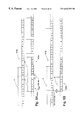
- FIG. 15 is a timing diagram illustrating random access channel and uplink frame structures used in a wireless communications system according to another embodiment of the present invention.
- FIG. 16 is a flowchart illustrating exemplary operations for communicating with a terminal according to another aspect of the present invention.
- FIG. 3 illustrates a base station, in particular, a base station subsystem (BSS) 300 including a base transceiver station (BTS) 320 and base station controller (BSC) 310 as commonly implemented in GSM-compliant systems, for communicating with a terminal 330 according to embodiments of the present invention described herein.
- the BTS 320 includes a receiver 321 and a transmitter 322 , each of which is coupled to an antenna 323 .
- Transmissions from a terminal 330 e.g., RACH bursts
- a propagation delay determiner 311 implemented in the BSC 310 , which determines a propagation delay between the BTS 320 and the terminal 330 .
- a timing information determiner 312 determines timing information, e.g., a timing advance value TA, that is transmitted to the terminal 330 by the transmitter 322 .
- TA timing advance value
- the discussion of FIGS. 4A-15 that follows will describe exemplary apparatus and operations for providing expanded range, and will be described in continuing reference to the base station 300 and terminal 330 apparatus illustrated in FIG. 3 .
- the BTS 320 and BSC 310 represent cellular network elements that are typically utilized in a wireless system conforming to the GSM recommendations.
- the BSC 310 may include a processor, e.g., a computer, microprocessor, microcontroller, or other data processing apparatus, in which the propagation delay determiner 311 and the timing information determiner 312 may be implemented, and which processes information received by the receiver 321 and produces information that is transmitted by the transmitter 322 .
- BTS or BSC components may also be present, such as mixers, duplexers, frequency synthesizers, power supplies and the like. Operations of such components are well known, and need not be discussed in detail herein. It will also be appreciated that the methods and apparatus of the present invention may be implemented using network architectures other than those utilized in GSM systems, such as network architectures of other time-division multiplexed systems (e.g., those conforming to IS-136 standards).
- FIGS. 6-7, 9 , 12 - 13 and 16 are flowchart illustrations of exemplary operations for communicating in a wireless communications system according to various aspects of the present invention. It will be understood that blocks of these flowcharts, and combinations of blocks in these flowcharts, can be implemented by computer program instructions which may be loaded and executed on a computer or other programmable data processing apparatus, such as a computer other data processing apparatus in the BSS 300 of FIG. 3, or in other components of a wireless communications system, to produce a machine such that the instructions which execute on the computer or other programmable data processing apparatus create means for implementing the functions specified in the flowchart block or blocks.
- a computer or other programmable data processing apparatus such as a computer other data processing apparatus in the BSS 300 of FIG. 3, or in other components of a wireless communications system, to produce a machine such that the instructions which execute on the computer or other programmable data processing apparatus create means for implementing the functions specified in the flowchart block or blocks.
- the computer program instructions may also be loaded onto a computer or other programmable data processing apparatus to cause a series of operational steps to be performed on the computer or other programmable apparatus to produce a computer implemented process such that the instructions which execute on the computer or other programmable apparatus provide steps for implementing the functions specified in the flowchart block or blocks.
- blocks of the flowcharts of FIGS. 6-7, 9 , 12 - 13 and 16 support combinations of means for performing the specified functions and combinations of steps for performing the specified functions. It will also be understood that each block of the flowcharts of FIGS. 6-7, 9 , 12 - 13 and 16 , and combinations of blocks therein, can be implemented by special purpose hardware-based computer systems which perform the specified functions or steps, or combinations of special purpose hardware and computer instructions.
- FIGS. 4A-4B and 5 transmissions from respective groups of terminals at respective ranges with respect to a BSS 300 are transmitted on respective different uplink carrier frequencies using respective time-offset frame structures.
- FIG. 4A illustrates a representative downlink frame structure 410 a and first and second uplink frame structures 420 a , 430 a on respective first and second frequencies at a BSS 300 .
- the downlink frame structure 410 a and the uplink frame structures 420 a , 430 a include respective series of frames F, each of which includes a series of time slots 0 - 7 .
- the first and second uplink frame structures 420 a , 430 a are used on respective first and second carrier frequencies to receive transmissions from terminals at respective ranges, e.g., from ranges B 0 and B 1 illustrated in FIG. 5 .
- the first and second uplink frame structures 420 a , 430 a are time-offset by a time interval T offset , here illustrated as the maximum amount of timing advance for a 6-bit timing advance value (64 bits) as used in a GSM system.
- FIG. 4B illustrates a representative downlink frame structure 410 b and a representative uplink frame structure 420 b at a terminal 330 , corresponding to the downlink and uplink frame structures 410 a , 420 a of FIG. 4 A.
- the terminal 330 in the range B 0 applies a timing advance TA, here shown as having a value of 0 to 63 bits, to the uplink frame structure 420 b , such the transmissions from the terminal 330 that occur at the terminal 330 according to the uplink frame structure 420 b arrive at the BSS 300 synchronized to the uplink frame structure 420 a.
- TA timing advance
- timing advance TA corresponds to the round-trip propagation delay PD between the terminal 330 and the BSS 300 (in bit periods), which may be calculated as function of the distance between the BSS 300 and the terminal 330 and the symbol period:
- the TA value is limited to be within a range of 0 to 63, and thus gives a maximum distance of 34.9 km between the BSS 300 and the terminal 330 .
- range may be extended by calculating TA as the modulus 64 of the round-trip propagation delay PD between the BSS 300 and the terminal 330 (the residue or remainder after dividing PD by 64):
- a BSS 300 communicating with a terminal 330 in a given one of the ranges transmits a timing advance value TA calculated as in (2), and instructs the terminal 330 to transmit on the carrier frequency associated with the range.
- the timing advance used in each range of the illustrated embodiment is within a range of 0 to 63.
- uplink bursts from terminals in different ranges are staggered upon arrival at the BSS 300 .
- uplink bursts from terminals in range B 0 arrive 468.75 bits (3 slots) behind the start of the downlink frame.
- the uplink bursts from terminals in range B 1 are delayed an additional 64 bits, and the uplink bursts from range B 2 are delayed an additional 64 bits with respect to the uplink bursts from range B 1 .
- the BSS 300 transmits first timing information, e.g., a first timing advance value, to a terminal 330 of a first group, e.g., a terminal 330 in the range B 0 illustrated in FIG. 5 (Block 610 ).
- the first timing information instructs the receiving terminal 330 to time its transmissions to arrive at the BSS 300 in synchronism with a first series of frames, e.g., the uplink frame structure 420 a .
- the BSS 300 transmits second timing information, e.g., a second timing advance value, to a terminal 330 in a second group, e.g., a terminal 330 in the range B 1 of FIG.
- the second timing information instructs this terminal 330 to time its transmissions to arrive at the BSS 300 in synchronism with a second series of frames that is time-offset with respect to the first series of frames, e.g., with the second uplink frame structure 430 a .
- the BSS 300 receives transmissions from the terminals on respective first and second carrier frequencies associated with the different series of frames, e.g., on the respective uplink carrier frequencies associated with the first and second uplink frame structures 420 a , 430 a (Block 630 ).
- FIG. 7 illustrates exemplary operations 700 according to another aspect of the present invention, namely, operations for handing over a terminal 330 as it moves between ranges in an multi-range cell structure such as that illustrated in FIG. 5 .
- First timing information that instructs a terminal 330 to time its transmissions on a first carrier frequency to arrive at a BSS 300 in synchronism with a first series of frames is transmitted to a terminal 330 when it is in a first range (Block 710 ).
- the BSS 300 receives transmissions from the terminal 330 on the first carrier frequency in synchronism with the first series of frames (Block 720 ).
- the BSS 300 transmits timing information to the terminal 330 that instructs the terminal 330 to time its transmissions on a second carrier frequency to arrive at the BSS 300 in synchronism with a second series of frames that is time-offset with respect to the first series of frames (Block 730 ).
- the BSS 300 then receives transmissions from the terminal 330 on the second carrier frequency in synchronism with the second series of frames (Block 740 ).
- FIGS. 8A-8B and 9 illustrate yet another embodiment of the present invention, one that is particularly advantageous for use in base stations that do not have multiple carrier frequencies to provide frequency separation of staggered terminal transmissions as described above.
- transmissions from respective groups of terminals at respective ranges with respect to a BSS 300 are transmitted on a common carrier frequency in synchronism with respective-offset frame structures that are multiplexed on the common carrier frequency.
- FIG. 8A illustrates a representative downlink frame structure 810 a and first and second uplink frame structures 820 a , 830 a at a BSS 300 .
- the downlink frame structure 810 a includes a series of frames F, each of which includes a series of time slots 0 - 7 , while the uplink frame structures 820 a , 830 a include respective series of frames F′, F′′, which include respective series of time slots 0 - 2 , 3 - 6 .
- the time-multiplexing of the frame structures 820 a , 830 a results in the loss of a portion of the available capacity on the common carrier frequency, as the second uplink frame structure 830 a is delayed with respect to the first uplink frame structure 820 a by a portion of a time slot.
- first and second uplink frame structures 820 a , 830 a are used on a common carrier frequency to receive transmissions from terminals at respective ranges, e.g., from ranges B 0 and B 1 illustrated in FIG. 5 .
- the first and second uplink frame structures 820 a , 830 a are time-offset by a time interval T offset , here illustrated as the maximum amount of timing advance (64 bits) for a 6-bit timing advance value as used in a GSM system.
- FIG. 8B illustrates a representative downlink frame structure 810 b and a representative uplink frame structure 820 b at a terminal 330 , corresponding to the downlink and uplink frame structures 810 a , 820 a of FIG. 4 A.
- the terminal 330 in range B 0 applies a timing advance TA, here shown as having a value of 0 to 63 bits, to the uplink frame structure 820 b , such the transmissions from the terminal 330 that occur at the terminal 330 according to the uplink frame structure 820 b arrive at the BSS 300 synchronized to the uplink frame structure 820 a .
- TA timing advance
- the system constrains the terminal 330 to transmission on the carrier frequency in slots 0 - 2 .
- This constraint is transparent to the terminal, which operates as it normally would in a GSM or other conventional system.
- the slots 3 - 6 are shown in dotted line in FIG. 8B to illustrate the relative position of these slots to the slots 0 - 2 used by the terminal in range B 0 ; the slots 3 - 6 may be assigned to a terminal in range B 1 such that that terminal's transmissions are timed to arrive at the BSS 300 in synchronism with the second uplink frame structure 830 a.
- FIG. 9 Exemplary system operations 900 according to this aspect of the present invention are illustrated in FIG. 9 .
- the BSS 300 transmits first timing information (e.g., a first timing advance value), to a terminal 330 of a first group (e.g., a terminal 330 in the range B 0 illustrated in FIG. 5) (Block 910 ).
- the first timing information 30 instructs the receiving terminal 330 to time its transmissions to arrive at the BSS 300 in synchronism with a first series of frames, e.g., the uplink frame structure 820 a of FIG. 8 A.
- the BSS 300 transmits second timing information (e.g., a second timing advance value), to a terminal 330 in a second group (e.g., a terminal 330 in the range B 1 of FIG. 5) (Block 920 ).
- the second timing information instructs this terminal 330 to time its transmissions to arrive at the BSS 300 in synchronism with a second series of frames that is time-offset with respect to the first series of frames, e.g., with the second uplink frame structure 830 a of FIG. 8 A.
- the BSS 300 receives transmissions from the terminals on a common carrier frequency, in synchronism with respective ones of the first and second uplink frame structures 820 a , 830 a (Block 930 ).
- FIGS. 10A-10B and 11 - 12 illustrate yet another embodiment of the present invention, in which overlapping ranges are used to provide hysteresis for a terminal 330 moving between ranges.
- the embodiments illustrated in FIGS. 4A-4B, 5 - 7 , and 8 A- 8 B may work well for fixed terminals and for mobile terminals that stay within a same range for the duration of a call. However, if a terminal moves from one range to another during a call, the call may need to be handed over to the carrier frequency allocated for that range. For proper handoff, the mobile terminal typically would have to maintain its connection for the old range in order to exchange handoff messages before switching over to the new carrier frequency. Because the frame structures are synchronized, the handoff message can include a new timing advance value to be used on the new channel, and the terminal can begin communication on the new channel with the new timing advance value.
- Handoff is preferably done slightly outside of the range (within about 1 ⁇ 2 km for the illustrated embodiments) so that the uplink burst time at the base station is not off by more than 1 bit period.
- ranges have some overlapping coverage area to prevent dropping of a call.
- the aspect of the present invention illustrated in FIGS. 10A-10B and 11 - 12 involves dividing a cell into overlapped ranges and, preferably, providing hysteresis into the handoff process to avoid frequent handoff between channels at the range edge.
- FIG. 10A illustrates a representative downlink frame structure 1010 a and first and second uplink frame structures 1020 a , 1030 a at a BSS 300 .
- the downlink frame structure 1010 a and the uplink frame structures 1020 a , 1030 a include respective series of frames F, each of which includes a series of time slots 0 - 7 .
- First and second uplink frame structures 1020 a , 1030 a are used on respective carrier frequencies to receive transmissions from terminals at respective ranges, e.g., from ranges B 0 and B 1 illustrated in FIG.
- the first and second uplink frame structures 1020 a , 1030 a are time-offset by a time interval T offset , which is an amount (52 bits) that is less than the maximum amount (64 bits) of timing advance for a 6-bit timing advance value as used in a GSM system.
- T offset is an amount (52 bits) that is less than the maximum amount (64 bits) of timing advance for a 6-bit timing advance value as used in a GSM system.
- FIG. 10B illustrates a representative downlink frame structure 1010 b and a representative uplink frame structure 1020 b at a terminal 330 in a range B 0 corresponding to the downlink and uplink frame structures 1010 a , 1020 a of FIG. 10 A.
- the terminal 330 in the range B 0 applies a timing advance TA, having a value between 0 and 63 bits to the uplink frame structure 1020 b , such that the transmissions from the terminal 330 that occur at the terminal 330 according to the uplink frame structure 1020 b arrive at the BSS 300 synchronized to the uplink frame structure 1020 a .
- the updated timing advance value chosen for a particular terminal in an overlapping region depends on which carrier frequency the terminal is currently using.
- FIG. 11 provides an example of overlapping of ranges B 0 , B 1 , B 2 that overlap for 12 bits of timing advance value, providing an overlap distance of about 6.6 km. If ( ⁇ d+ ⁇ ) is the distance of each range within a large cell, and ⁇ is the overlapping distance, the range of a range B 1 is given by:
- timing advance is within the range of 0 to 63. However, in the area of overlap of two ranges, two different timing advance values may be sent to a terminal, depending on the current state of the terminal.
- FIG. 12 illustrates exemplary operations 1200 for providing hysteresis as a terminal 330 moves between overlapping ranges.
- a BSS 300 transmits first timing information to a terminal 330 when the terminal 330 is in a first range, the first timing information instructing the terminal 330 to time its transmissions to arrive at the BSS 300 in synchronism with a first series of frames (Block 1210 ).
- the BSS 300 receives a transmission from the terminal 330 on a first carrier frequency in synchronism with the first series of frames (Block 1220 ).
- the BSS 300 In response to movement of the terminal 330 to a portion of a second, overlapping range, in particular, a portion of the second range that lies outside of the first range, the BSS 300 transmits second timing information to instruct the terminal 330 to synchronize its transmissions to a second series of frames that is time-offset with respect to the first series of frames (Block 1230 ). The BSS 300 then receives a transmission from the terminal 330 on a second carrier frequency in synchronism with the second series of frames (Block 1240 ).
- the BSS 300 In response to the terminal 330 moving from the second range to a portion of the first range that lies outside of the second range, the BSS 300 again transmits timing information instructing the terminal 330 to again synchronize its transmissions to the first series of frames (Block 1250 ). The BSS 300 then receives a transmission from the terminal 330 in synchronism with the first series of frames (Block 1260 ).
- timing advance values TA i.e., the values sent to the terminal, may be computed as follows:
- TA mod 64 ( PD+n *12) for range n.
- Exemplary operations 1300 for computing TA are shown in FIG. 13 .
- An initial round-trip propagation delay PD ini is determined, e.g., from a RACH burst (Block 1310 ).
- the BSS 300 determines in which range B n the terminal 330 is located (Block 1320 ).
- the BSS 300 then computes the timing advance TA and conveys it to the terminal 330 (Block 1330 ).
- the BSS 300 determines an updated round-trip propagation delay PD new (Block 1340 ).
- the BSS 300 updates range B n (Block 1350 ), and computes a new timing advance value TA using the updated n (Block 1360 ). If not, the BSS 300 leaves n unchanged in computing the new timing advance value TA (Block 1360 ). The BSS 300 repeats operations for determining the timing advance (Blocks 1350 and/or 1360 ), for each new propagation delay value PD new (Block 1340 ).
- This manner of computing timing advance helps reduce the frequency of switching between carriers (or between frames in a single carrier) during a call, providing hysteresis as the terminal 330 moves between ranges.
- 4 bits of overlap (approximately 2.2 km).
- range boundaries may be established such that switching between staggered frame structures occurs at values intermediate to the maximum and minimum TA values. An example of such boundary definition is shown in FIG.
- FIGS. 15-16 illustrate yet another aspect of the present invention, in particular, an exemplary technique for providing access for terminals using an expanded slot RACH frame 1540 , and for assigning terminals to slots on staggered traffic channel frames 1520 , 1530 .
- Terminals in an expanded-range cell transmit RACH burst that are timed to fall within “expanded” RACH slots of a first carrier frequency, where the expanded slots 1541 , 1542 beginning with slots 0 and 3 are provided by not assigning traffic to “normal” slots 1 and 4 .
- the RACH slots 1541 , 1542 are expanded to tolerate increased propagation delay from terminals at outer reaches of the expanded cell.
- the BSS 300 may assign a terminal to a slot on one of first and second carriers with staggered frame structures 1520 , 1530 , as described with reference to FIGS. 4A-4B above, or to slots of time-multiplexed staggered frames as describe with reference to FIGS. 8A-8B.
- a BSS 300 receives a RACH burst in an expanded RACH slot (Block 1610 ). Based on the timing of the RACH burst, the BSS 300 determines the propagation delay for the terminal 330 (Block 1620 ). Based on whether the propagation delay indicates that the terminal 330 is in a first range or a second range, the BSS 300 transmits first or second timing information that instructs the terminal 330 to time its transmissions to arrive in synchronism with one of first or second time-offset series of frames, which may be on separate carriers or multiplexed on the same carrier (Block 1630 ). The BSS 300 then receives a transmission from the terminal 330 in synchronism with the appropriate series of frames (Block 1640 ).
Abstract
Description
Claims (38)
Priority Applications (5)
| Application Number | Priority Date | Filing Date | Title |
|---|---|---|---|
| US09/372,015 US6633559B1 (en) | 1999-08-11 | 1999-08-11 | Apparatus and methods for extended base station range using staggered uplink frame structures |
| CN00814031A CN1378761A (en) | 1999-08-11 | 2000-07-31 | Apparatus and methods for extended base station range using staggered uplink frame structures |
| DE10084914T DE10084914T1 (en) | 1999-08-11 | 2000-07-31 | Devices and methods for an expanded base station area using staggered uplink frame structures |
| AU66168/00A AU6616800A (en) | 1999-08-11 | 2000-07-31 | Apparatus and methods for extended base station range using staggered uplink frame structures |
| PCT/US2000/020927 WO2001011907A1 (en) | 1999-08-11 | 2000-07-31 | Apparatus and methods for extended base station range using staggered uplink frame structures |
Applications Claiming Priority (1)
| Application Number | Priority Date | Filing Date | Title |
|---|---|---|---|
| US09/372,015 US6633559B1 (en) | 1999-08-11 | 1999-08-11 | Apparatus and methods for extended base station range using staggered uplink frame structures |
Publications (1)
| Publication Number | Publication Date |
|---|---|
| US6633559B1 true US6633559B1 (en) | 2003-10-14 |
Family
ID=23466351
Family Applications (1)
| Application Number | Title | Priority Date | Filing Date |
|---|---|---|---|
| US09/372,015 Expired - Lifetime US6633559B1 (en) | 1999-08-11 | 1999-08-11 | Apparatus and methods for extended base station range using staggered uplink frame structures |
Country Status (5)
| Country | Link |
|---|---|
| US (1) | US6633559B1 (en) |
| CN (1) | CN1378761A (en) |
| AU (1) | AU6616800A (en) |
| DE (1) | DE10084914T1 (en) |
| WO (1) | WO2001011907A1 (en) |
Cited By (58)
| Publication number | Priority date | Publication date | Assignee | Title |
|---|---|---|---|---|
| US20010036168A1 (en) * | 2000-04-06 | 2001-11-01 | Terry Stephen E. | Synchronization of timing advance and deviation |
| US20020094820A1 (en) * | 2000-12-19 | 2002-07-18 | Nokia Networks Oy | Network-based method and system for determining a location of user equipment in CDMA networks |
| US20020131426A1 (en) * | 2000-06-22 | 2002-09-19 | Mati Amit | Scalable virtual channel |
| US20030002459A1 (en) * | 2001-06-27 | 2003-01-02 | Hironobu Igarashi | Base station transceiver sub-system and frame offset allocation method thereof |
| US20030026215A1 (en) * | 1996-11-07 | 2003-02-06 | Schafer David C. | System and method for minimizing guard time in a time division duplex communication system |
| US20040073392A1 (en) * | 2002-07-01 | 2004-04-15 | Ari Immonen | Method and arrangement for improving the accuracy of positioning-related time measurements in radio system |
| US6785553B2 (en) | 1998-12-10 | 2004-08-31 | The Directv Group, Inc. | Position location of multiple transponding platforms and users using two-way ranging as a calibration reference for GPS |
| US20040203877A1 (en) * | 2002-10-17 | 2004-10-14 | Golden Stuart A. | Two-way ranging techniques |
| US6940838B1 (en) * | 1999-08-19 | 2005-09-06 | Invertix Corporation | Wireless telephone network optimization |
| US6996060B1 (en) | 2001-03-20 | 2006-02-07 | Arraycomm, Inc. | Closing a communications stream between terminals of a communications system |
| US20060121855A1 (en) * | 2004-12-07 | 2006-06-08 | Motorola, Inc. | System and method for adjusting a range of access for a cell |
| US7089000B1 (en) * | 1999-03-18 | 2006-08-08 | The Directv Group, Inc. | Multi-node wireless communication system with multiple transponding platforms |
| US20060193280A1 (en) * | 2004-12-29 | 2006-08-31 | Samsung Electronics Co., Ltd. | Relay communication method for an OFDMA-based cellular communication system |
| US20070217343A1 (en) * | 2005-08-19 | 2007-09-20 | Opnet Technologies, Inc. | Estimation of time-varying latency based on network trace information |
| US7339906B1 (en) * | 2001-03-20 | 2008-03-04 | Arraycomm, Llc | Opening a communications stream between a user terminal and a base station |
| WO2008025373A1 (en) * | 2006-08-29 | 2008-03-06 | Telefonaktiebolaget Lm Ericsson (Publ) | Detection of access bursts in a random access channel |
| US20080102753A1 (en) * | 2006-10-30 | 2008-05-01 | Mitsubishi Electric Corporation | Transmission method in a wireless telecommunication system including at least a base station intended to communicate with terminals |
| WO2009061255A1 (en) * | 2007-11-05 | 2009-05-14 | Telefonaktiebolaget L M Ericsson (Publ) | Random access preamble collision detection |
| US20090161654A1 (en) * | 2007-12-20 | 2009-06-25 | Research In Motion Limited | System and Method for Uplink Timing Synchronization |
| US20090310556A1 (en) * | 2007-01-09 | 2009-12-17 | Ntt Docomo, Inc. | Base station, mobile communication system, mobile station and communication control method |
| US20100097962A1 (en) * | 2006-09-28 | 2010-04-22 | Toru Sahara | Communication Control Method, Base Station Device, Terminal Device, and Communication Control System Using TDD-OFDMA Communication Method |
| US20100135235A1 (en) * | 2008-12-01 | 2010-06-03 | Qualcomm Incorporated | Blank subframe uplink design |
| US20100157959A1 (en) * | 2008-12-20 | 2010-06-24 | Motorola, Inc. | Method and device for assigning traffic channels in a wireless communication system |
| US20100220713A1 (en) * | 2007-11-05 | 2010-09-02 | Tobias Tynderfeldt | Random access preamble collision detection |
| US20100235704A1 (en) * | 2007-11-06 | 2010-09-16 | Fredrik Gunnarsson | Methods and arrangements in a wireless communication system |
| US20100254356A1 (en) * | 2007-11-05 | 2010-10-07 | Telefonaktiebolaget L M Ericsson (Publ) | Timing Alignment in an LTE System |
| US20110070874A1 (en) * | 2009-08-07 | 2011-03-24 | Vodafone Group Plc | Dynamically selecting a cell range of a base station |
| WO2011043711A1 (en) * | 2009-10-09 | 2011-04-14 | Telefonaktiebolaget L M Ericsson (Publ) | Extended cell range |
| US20110103499A1 (en) * | 2009-10-29 | 2011-05-05 | Fang-Chen Cheng | Method for range extension in wireless communication systems |
| CN102083197A (en) * | 2010-12-23 | 2011-06-01 | 华为技术有限公司 | Method, equipment and system for processing time advance |
| US20110128873A1 (en) * | 2009-11-27 | 2011-06-02 | Farag Emad N | Ultra Large Cell Communications |
| US20110158116A1 (en) * | 2009-06-19 | 2011-06-30 | Qualcomm Incorporation | Method and apparatus that facilitates a timing alignment in a multicarrier system |
| US20110171949A1 (en) * | 2010-01-08 | 2011-07-14 | Mediatek Inc. | Two-step uplink synchronization for pico/femtocell |
| US20110216718A1 (en) * | 2010-03-03 | 2011-09-08 | Rene Faurie | Methods and apparatus to signal access-stratum capabilities of mobile stations for data transfer sessions |
| US20110217980A1 (en) * | 2010-03-03 | 2011-09-08 | Rene Faurie | Methods and apparatus to indicate space requirements for communicating capabilities of a device |
| US20110216719A1 (en) * | 2010-03-03 | 2011-09-08 | Rene Faurie | Methods and apparatus to signal use-specific capabilities of mobile stations to establish data transfer sessions |
| US20110216720A1 (en) * | 2010-03-03 | 2011-09-08 | Rene Faurie | Methods and apparatus to initiate data transfers using capabilities classes of pre-defined capability configurations |
| EP2365717A1 (en) * | 2010-03-12 | 2011-09-14 | Research In Motion Limited | Communication station and method for transmitting on a random access channel |
| US20110222492A1 (en) * | 2010-03-12 | 2011-09-15 | Borsella Remo | Methods and apparatus for registration and data transmission using fast/zero contention resolution |
| US20110222527A1 (en) * | 2010-03-12 | 2011-09-15 | David Philip Hole | Base stations and methods for receiving transmissions on an enhanced random access channel |
| US20110222476A1 (en) * | 2010-03-12 | 2011-09-15 | David Philip Hole | Communication stations and methods for transmitting additional information on an enhanced random access channel |
| US20110223932A1 (en) * | 2010-03-12 | 2011-09-15 | David Philip Hole | Timing advance enhancements for cellular communications |
| US20120004002A1 (en) * | 2007-08-10 | 2012-01-05 | Panasonic Corporation | Terminal device and base station device |
| US20120087270A1 (en) * | 2009-04-24 | 2012-04-12 | Huawei Technologies Co., Ltd. | Uplink synchronization method and apparatus |
| US8160609B2 (en) | 2008-11-26 | 2012-04-17 | Andrew Llc | System and method for multiple range estimation location |
| US8249622B2 (en) | 2008-11-26 | 2012-08-21 | Andrew, Llc | System and method for multiple range estimation location |
| US20130215874A1 (en) * | 2012-02-15 | 2013-08-22 | Huawei Technologies Co., Ltd. | Communication method, user equipment and base station |
| EP2637457A1 (en) * | 2010-11-03 | 2013-09-11 | Datang Mobile Communications Equipment Co., Ltd. | Method, system, and device for information notification and timing advance acquisition |
| EP2670200A1 (en) * | 2011-01-27 | 2013-12-04 | Fujitsu Limited | Base-station device, mobile-station device, wireless-communication method, and wireless-communication system |
| US8675629B2 (en) * | 2011-06-27 | 2014-03-18 | General Motors Llc | Timing adjustment for extending the wireless range of a vehicle telematics unit |
| US20140133475A1 (en) * | 2012-11-14 | 2014-05-15 | Electronics And Telecommunications Research Institute | System and method for random access wireless communication |
| WO2014101236A1 (en) * | 2012-12-31 | 2014-07-03 | 华为技术有限公司 | Uplink channel interference coordinating method and base station |
| US20150085834A1 (en) * | 2013-09-26 | 2015-03-26 | Qualcomm Incorporated | Time division long term evolution (td-lte) frame structure modification |
| US20160029335A1 (en) * | 2009-02-06 | 2016-01-28 | Thomson Licensing | Method for reception in a wireless network and corresponding device for reception |
| US9356740B2 (en) | 2011-11-10 | 2016-05-31 | Huawei Technologies Co., Ltd. | Method, apparatus, and system for facilitating random access |
| GB2559382A (en) * | 2017-02-03 | 2018-08-08 | Tcl Communication Ltd | Systems and methods for cell range extension |
| US11160041B2 (en) * | 2018-06-18 | 2021-10-26 | Qualcomm Incorporated | Timing advance indication |
| US20220346048A1 (en) * | 2019-09-23 | 2022-10-27 | Skylo Technologies, Inc. | Transmission Management |
Families Citing this family (15)
| Publication number | Priority date | Publication date | Assignee | Title |
|---|---|---|---|---|
| US6822969B2 (en) * | 2003-04-03 | 2004-11-23 | Motorola, Inc. | Method and apparatus for scheduling asynchronous transmissions |
| CN1925363B (en) * | 2005-08-31 | 2011-04-13 | 华为技术有限公司 | Method and device for realizing physical random switch-in channel transmission time delay under wide covering |
| TWI472198B (en) | 2006-01-31 | 2015-02-01 | Interdigital Tech Corp | Method and apparatus for providing and utilizing a non-contention based channel in a wireless communication system |
| CN101075844B (en) * | 2006-05-17 | 2010-07-21 | 大唐移动通信设备有限公司 | Method for expanding time-division synchronous CDMA access system coverage |
| WO2008097142A1 (en) * | 2007-02-05 | 2008-08-14 | Telefonaktiebolaget Lm Ericsson (Publ) | A method for improved random access in a cellular wireless access system |
| WO2009002243A1 (en) * | 2007-06-26 | 2008-12-31 | Telefonaktiebolaget Lm Ericsson (Publ) | Varied cell size in a time division duplex system |
| US8886205B2 (en) * | 2009-03-02 | 2014-11-11 | Qualcomm Incorporated | Timing adjustment for synchronous operation in a wireless network |
| CN102148670B (en) * | 2010-02-10 | 2013-04-24 | 中国移动通信集团公司 | Timing advance (TA) value indication method and device |
| EP2427018B1 (en) * | 2010-09-07 | 2016-02-17 | Alcatel Lucent | Access to a wireless communications network by a transceiver equipment selecting a non-zero timing advance value used for sending a Random Access Channel preamble to a LTE base station |
| CN103580800B (en) * | 2012-08-10 | 2017-11-03 | 华为技术有限公司 | A kind of method of demodulation, equipment and system |
| CN105409272B (en) * | 2013-02-19 | 2019-09-13 | 华为技术有限公司 | A kind of method and device of uplink signal transmissions timing |
| US10693574B2 (en) | 2015-07-02 | 2020-06-23 | Qualcomm Incorporated | Method and apparatus for efficient data transmissions in half-duplex communication systems with large propagation delays |
| SG11201906947SA (en) | 2017-02-17 | 2019-08-27 | Bristol Myers Squibb Co | Antibodies to alpha-synuclein and uses thereof |
| US10574496B2 (en) * | 2017-03-27 | 2020-02-25 | Telefonaktiebolaget Lm Ericsson (Publ) | Coding scheme and extended synchronization access burst for EC-GSM-IoT enhancement |
| CN110838898B (en) * | 2018-08-15 | 2021-01-26 | 上海朗帛通信技术有限公司 | Method and device used in wireless communication node |
Citations (13)
| Publication number | Priority date | Publication date | Assignee | Title |
|---|---|---|---|---|
| EP0564429A2 (en) | 1992-03-30 | 1993-10-06 | Telefonaktiebolaget Lm Ericsson | Cell extension in a cellular telephone system |
| EP0687079A2 (en) | 1994-06-08 | 1995-12-13 | Alcatel N.V. | An extended range TDMA system |
| US5483537A (en) | 1993-03-03 | 1996-01-09 | Alcatel Radiotelephone | Method for allocating a timeslot within a frame to a mobile entering a communications cell and base transceiver station implementing this method |
| US5839071A (en) | 1993-09-21 | 1998-11-17 | Telstra Corporation Limited | Base station for a mobile telecommunications system |
| US6169887B1 (en) * | 1999-03-02 | 2001-01-02 | Motorola, Inc. | Range extension within a communication system |
| US6192247B1 (en) * | 1999-06-28 | 2001-02-20 | Motorola, Inc. | Method for extending the cell radius between a mobile station and a base station |
| US6212405B1 (en) * | 1998-08-31 | 2001-04-03 | Lucent Technologies Inc. | Extended range concentric cell base station |
| US6304759B1 (en) * | 1998-08-31 | 2001-10-16 | Lucent Technologies Inc. | Method for extending the range of a wireless communication system |
| US6363261B1 (en) * | 1998-08-31 | 2002-03-26 | Lucent Technologies Inc. | Extended range concentric cell base station |
| US6370397B1 (en) * | 1998-05-01 | 2002-04-09 | Telefonaktiebolaget Lm Ericsson (Publ) | Search window delay tracking in code division multiple access communication systems |
| US6370128B1 (en) * | 1997-01-22 | 2002-04-09 | Nokia Telecommunications Oy | Method for control channel range extension in a cellular radio system, and a cellular radio system |
| US6373833B1 (en) * | 1996-07-25 | 2002-04-16 | Nokia Telecommunications Oy | Cell expansion in a time division cellular system using frequency converting repeaters |
| US6424633B1 (en) * | 1996-02-09 | 2002-07-23 | Siemens Ag | Radio relay arrangement for extending the range on the radio link of a telecommunication system |
-
1999
- 1999-08-11 US US09/372,015 patent/US6633559B1/en not_active Expired - Lifetime
-
2000
- 2000-07-31 AU AU66168/00A patent/AU6616800A/en not_active Abandoned
- 2000-07-31 DE DE10084914T patent/DE10084914T1/en not_active Withdrawn
- 2000-07-31 WO PCT/US2000/020927 patent/WO2001011907A1/en active Application Filing
- 2000-07-31 CN CN00814031A patent/CN1378761A/en active Pending
Patent Citations (14)
| Publication number | Priority date | Publication date | Assignee | Title |
|---|---|---|---|---|
| EP0564429A2 (en) | 1992-03-30 | 1993-10-06 | Telefonaktiebolaget Lm Ericsson | Cell extension in a cellular telephone system |
| US5483537A (en) | 1993-03-03 | 1996-01-09 | Alcatel Radiotelephone | Method for allocating a timeslot within a frame to a mobile entering a communications cell and base transceiver station implementing this method |
| US5839071A (en) | 1993-09-21 | 1998-11-17 | Telstra Corporation Limited | Base station for a mobile telecommunications system |
| EP0687079A2 (en) | 1994-06-08 | 1995-12-13 | Alcatel N.V. | An extended range TDMA system |
| US5615215A (en) * | 1994-06-08 | 1997-03-25 | Alcatel N.V. | Extended range TDMA system |
| US6424633B1 (en) * | 1996-02-09 | 2002-07-23 | Siemens Ag | Radio relay arrangement for extending the range on the radio link of a telecommunication system |
| US6373833B1 (en) * | 1996-07-25 | 2002-04-16 | Nokia Telecommunications Oy | Cell expansion in a time division cellular system using frequency converting repeaters |
| US6370128B1 (en) * | 1997-01-22 | 2002-04-09 | Nokia Telecommunications Oy | Method for control channel range extension in a cellular radio system, and a cellular radio system |
| US6370397B1 (en) * | 1998-05-01 | 2002-04-09 | Telefonaktiebolaget Lm Ericsson (Publ) | Search window delay tracking in code division multiple access communication systems |
| US6363261B1 (en) * | 1998-08-31 | 2002-03-26 | Lucent Technologies Inc. | Extended range concentric cell base station |
| US6304759B1 (en) * | 1998-08-31 | 2001-10-16 | Lucent Technologies Inc. | Method for extending the range of a wireless communication system |
| US6212405B1 (en) * | 1998-08-31 | 2001-04-03 | Lucent Technologies Inc. | Extended range concentric cell base station |
| US6169887B1 (en) * | 1999-03-02 | 2001-01-02 | Motorola, Inc. | Range extension within a communication system |
| US6192247B1 (en) * | 1999-06-28 | 2001-02-20 | Motorola, Inc. | Method for extending the cell radius between a mobile station and a base station |
Non-Patent Citations (4)
| Title |
|---|
| "The Issue of GSM/EDGE/GPRS-136HS Time Alignment for Large/Rural Cells with Extra Long Propagation Delay," UWCC.GTF.PDFG/99.03.09, Flamingo Hilton, Reno, NV, Mar. 9-11, 1999, 3 pages. |
| "The Issue of GSM/EDGE/GPRS-136HS Time Alignment for Large/Rural Cells with Extra Long Propagation Delay," UWCC.GTF.PDFG/99.03.09, Flamingo Hilton, Reno, NV, Mar. 9-11, 1999, 3 pages. </STEXT> |
| International Search Report, PCT/US00/20927, Jan. 9, 2001. |
| International Search Report, PCT/US00/20927, Jan. 9, 2001.</STEXT> |
Cited By (130)
| Publication number | Priority date | Publication date | Assignee | Title |
|---|---|---|---|---|
| US20030026215A1 (en) * | 1996-11-07 | 2003-02-06 | Schafer David C. | System and method for minimizing guard time in a time division duplex communication system |
| US7031295B2 (en) * | 1996-11-07 | 2006-04-18 | Harris Corporation | System and method for minimizing guard time in a time division duplex communication system |
| US6785553B2 (en) | 1998-12-10 | 2004-08-31 | The Directv Group, Inc. | Position location of multiple transponding platforms and users using two-way ranging as a calibration reference for GPS |
| US7089000B1 (en) * | 1999-03-18 | 2006-08-08 | The Directv Group, Inc. | Multi-node wireless communication system with multiple transponding platforms |
| US6940838B1 (en) * | 1999-08-19 | 2005-09-06 | Invertix Corporation | Wireless telephone network optimization |
| US20010036168A1 (en) * | 2000-04-06 | 2001-11-01 | Terry Stephen E. | Synchronization of timing advance and deviation |
| US20020080749A1 (en) * | 2000-04-06 | 2002-06-27 | Interdigital Technology Corporation | Synchronization of timing advance and deviation |
| US20090262713A1 (en) * | 2000-04-06 | 2009-10-22 | Interdigital Technology Corporation | Synchronization of timing advance and deviation |
| US7573913B2 (en) * | 2000-04-06 | 2009-08-11 | Interdigital Technology Corporation | Synchronization of timing advance and deviation |
| US7023835B2 (en) | 2000-04-06 | 2006-04-04 | Interdigital Technology Corporation | Synchronization of timing advance and deviation |
| US7274679B2 (en) * | 2000-06-22 | 2007-09-25 | Mati Amit | Scalable virtual channel |
| US20020131426A1 (en) * | 2000-06-22 | 2002-09-19 | Mati Amit | Scalable virtual channel |
| US20020094820A1 (en) * | 2000-12-19 | 2002-07-18 | Nokia Networks Oy | Network-based method and system for determining a location of user equipment in CDMA networks |
| US7254401B2 (en) * | 2000-12-19 | 2007-08-07 | Nokia Corporation | Network-based method and system for determining a location of user equipment in CDMA networks |
| US6996060B1 (en) | 2001-03-20 | 2006-02-07 | Arraycomm, Inc. | Closing a communications stream between terminals of a communications system |
| US7339906B1 (en) * | 2001-03-20 | 2008-03-04 | Arraycomm, Llc | Opening a communications stream between a user terminal and a base station |
| US20030002459A1 (en) * | 2001-06-27 | 2003-01-02 | Hironobu Igarashi | Base station transceiver sub-system and frame offset allocation method thereof |
| US7187905B2 (en) * | 2002-07-01 | 2007-03-06 | Nokia Corporation | Method and arrangement for improving the accuracy of positioning-related time measurements in radio system |
| US20040073392A1 (en) * | 2002-07-01 | 2004-04-15 | Ari Immonen | Method and arrangement for improving the accuracy of positioning-related time measurements in radio system |
| US20040203877A1 (en) * | 2002-10-17 | 2004-10-14 | Golden Stuart A. | Two-way ranging techniques |
| US20060121855A1 (en) * | 2004-12-07 | 2006-06-08 | Motorola, Inc. | System and method for adjusting a range of access for a cell |
| US20060193280A1 (en) * | 2004-12-29 | 2006-08-31 | Samsung Electronics Co., Ltd. | Relay communication method for an OFDMA-based cellular communication system |
| US20070217343A1 (en) * | 2005-08-19 | 2007-09-20 | Opnet Technologies, Inc. | Estimation of time-varying latency based on network trace information |
| US7843815B2 (en) * | 2005-08-19 | 2010-11-30 | Opnet Technologies, Inc. | Estimation of time-varying latency based on network trace information |
| US8155251B2 (en) | 2006-08-29 | 2012-04-10 | Telefonaktiebolaget Lm Ericsson (Publ) | Detection of access bursts in a random access channel |
| WO2008025373A1 (en) * | 2006-08-29 | 2008-03-06 | Telefonaktiebolaget Lm Ericsson (Publ) | Detection of access bursts in a random access channel |
| US20100002573A1 (en) * | 2006-08-29 | 2010-01-07 | Robert Baldemair | Detection of Access Bursts in a Random Access Channel |
| US8179823B2 (en) | 2006-09-28 | 2012-05-15 | Kyocera Corporation | Communication control method, base station device, terminal device, and communication control system using TDD-OFDMA communication method |
| US20100097962A1 (en) * | 2006-09-28 | 2010-04-22 | Toru Sahara | Communication Control Method, Base Station Device, Terminal Device, and Communication Control System Using TDD-OFDMA Communication Method |
| US20080102753A1 (en) * | 2006-10-30 | 2008-05-01 | Mitsubishi Electric Corporation | Transmission method in a wireless telecommunication system including at least a base station intended to communicate with terminals |
| US7885673B2 (en) * | 2006-10-30 | 2011-02-08 | Mitsubishi Electric Corporation | Transmission method in a wireless telecommunication system including at least a base station intended to communicate with terminals |
| US20090310556A1 (en) * | 2007-01-09 | 2009-12-17 | Ntt Docomo, Inc. | Base station, mobile communication system, mobile station and communication control method |
| US8385186B2 (en) * | 2007-01-09 | 2013-02-26 | Ntt Docomo, Inc. | Base station, mobile communication system, mobile station and communication control method |
| US20120004002A1 (en) * | 2007-08-10 | 2012-01-05 | Panasonic Corporation | Terminal device and base station device |
| US8280421B2 (en) * | 2007-08-10 | 2012-10-02 | Panasonic Corporation | Terminal device and base station device |
| US20100254356A1 (en) * | 2007-11-05 | 2010-10-07 | Telefonaktiebolaget L M Ericsson (Publ) | Timing Alignment in an LTE System |
| US20100220713A1 (en) * | 2007-11-05 | 2010-09-02 | Tobias Tynderfeldt | Random access preamble collision detection |
| JP2011503959A (en) * | 2007-11-05 | 2011-01-27 | テレフオンアクチーボラゲット エル エム エリクソン(パブル) | Random access preamble collision detection |
| US9468023B2 (en) | 2007-11-05 | 2016-10-11 | Telefonaktiebolaget Lm Ericsson (Publ) | Timing alignment in an LTE system |
| US9204468B2 (en) * | 2007-11-05 | 2015-12-01 | Telefonaktiebolaget L M Ericsson (Publ) | Timing alignment in an LTE system |
| US8411664B2 (en) | 2007-11-05 | 2013-04-02 | Telefonaktiebolaget Lm Ericsson (Publ) | Random access preamble collision detection |
| US10257793B2 (en) | 2007-11-05 | 2019-04-09 | Telefonaktiebolaget Lm Ericsson (Publ) | Timing alignment in an LTE system |
| US10736060B2 (en) | 2007-11-05 | 2020-08-04 | Telefonaktiebolaget Lm Ericsson (Publ) | Timing alignment in an LTE system |
| WO2009061255A1 (en) * | 2007-11-05 | 2009-05-14 | Telefonaktiebolaget L M Ericsson (Publ) | Random access preamble collision detection |
| US20100235704A1 (en) * | 2007-11-06 | 2010-09-16 | Fredrik Gunnarsson | Methods and arrangements in a wireless communication system |
| US8583974B2 (en) | 2007-11-06 | 2013-11-12 | Telefonaktiebolaget L M Ericsson (Publ) | Methods and arrangements for holding target ratio for power loop in a wireless communication system |
| US9078216B2 (en) | 2007-11-06 | 2015-07-07 | Idtp Holdings, Inc. | Methods and arrangements in a wireless communication system |
| US9832731B2 (en) | 2007-11-06 | 2017-11-28 | Idtp Holdings, Inc. | Methods and arrangements in a wireless communication system |
| US8385320B2 (en) * | 2007-12-20 | 2013-02-26 | Research In Motion Limited | System and method for uplink timing synchronization |
| US20090161654A1 (en) * | 2007-12-20 | 2009-06-25 | Research In Motion Limited | System and Method for Uplink Timing Synchronization |
| US8391272B2 (en) | 2007-12-20 | 2013-03-05 | Research In Motion Corporation | System and method for uplink timing synchronization |
| US8249622B2 (en) | 2008-11-26 | 2012-08-21 | Andrew, Llc | System and method for multiple range estimation location |
| US8160609B2 (en) | 2008-11-26 | 2012-04-17 | Andrew Llc | System and method for multiple range estimation location |
| US8879461B2 (en) * | 2008-12-01 | 2014-11-04 | Qualcomm Incorporated | Blank subframe uplink design |
| US9125217B2 (en) | 2008-12-01 | 2015-09-01 | Qualcomm Incorporated | Blank subframe uplink design |
| US20100135235A1 (en) * | 2008-12-01 | 2010-06-03 | Qualcomm Incorporated | Blank subframe uplink design |
| US20100157959A1 (en) * | 2008-12-20 | 2010-06-24 | Motorola, Inc. | Method and device for assigning traffic channels in a wireless communication system |
| US10117202B2 (en) * | 2009-02-06 | 2018-10-30 | Thomson Licensing | Method for reception in a wireless network and corresponding device for reception |
| US20160029335A1 (en) * | 2009-02-06 | 2016-01-28 | Thomson Licensing | Method for reception in a wireless network and corresponding device for reception |
| US20120087270A1 (en) * | 2009-04-24 | 2012-04-12 | Huawei Technologies Co., Ltd. | Uplink synchronization method and apparatus |
| US9107160B2 (en) * | 2009-04-24 | 2015-08-11 | Huawei Technolgoies Co., Ltd. | Uplink synchronization method and apparatus |
| US20110158116A1 (en) * | 2009-06-19 | 2011-06-30 | Qualcomm Incorporation | Method and apparatus that facilitates a timing alignment in a multicarrier system |
| US8634313B2 (en) * | 2009-06-19 | 2014-01-21 | Qualcomm Incorporated | Method and apparatus that facilitates a timing alignment in a multicarrier system |
| US20110070874A1 (en) * | 2009-08-07 | 2011-03-24 | Vodafone Group Plc | Dynamically selecting a cell range of a base station |
| US8805446B2 (en) * | 2009-08-07 | 2014-08-12 | Vodafone Group Plc | Cell range selection based on UE distance and base station capacity |
| AU2010303984B2 (en) * | 2009-10-09 | 2013-10-17 | Telefonaktiebolaget L M Ericsson (Publ) | Extended cell range |
| CN102577551B (en) * | 2009-10-09 | 2015-03-25 | 瑞典爱立信有限公司 | Extended cell range |
| US20110085491A1 (en) * | 2009-10-09 | 2011-04-14 | Tobias Tynderfeldt | Extended Cell Range |
| WO2011043711A1 (en) * | 2009-10-09 | 2011-04-14 | Telefonaktiebolaget L M Ericsson (Publ) | Extended cell range |
| JP2013507823A (en) * | 2009-10-09 | 2013-03-04 | テレフオンアクチーボラゲット エル エム エリクソン(パブル) | Extend cell range |
| CN102577551A (en) * | 2009-10-09 | 2012-07-11 | 瑞典爱立信有限公司 | Extended cell range |
| US8831034B2 (en) * | 2009-10-09 | 2014-09-09 | Telefonaktiebolaget Lm Ericsson (Publ) | Methods and apparatus for handling time alignment in a cell with extended cell range |
| US20110103499A1 (en) * | 2009-10-29 | 2011-05-05 | Fang-Chen Cheng | Method for range extension in wireless communication systems |
| US8717972B2 (en) * | 2009-10-29 | 2014-05-06 | Alcatel Lucent | Method for range extension in wireless communication systems |
| US20110128873A1 (en) * | 2009-11-27 | 2011-06-02 | Farag Emad N | Ultra Large Cell Communications |
| US8855044B2 (en) | 2010-01-08 | 2014-10-07 | Mediatek Inc. | Two-step uplink synchronization for pico/femtocell |
| US20110171949A1 (en) * | 2010-01-08 | 2011-07-14 | Mediatek Inc. | Two-step uplink synchronization for pico/femtocell |
| US9173198B2 (en) | 2010-03-03 | 2015-10-27 | Blackberry Limited | Methods and apparatus to indicate space requirements for communicating capabilities of a device |
| US20110216719A1 (en) * | 2010-03-03 | 2011-09-08 | Rene Faurie | Methods and apparatus to signal use-specific capabilities of mobile stations to establish data transfer sessions |
| US20110217980A1 (en) * | 2010-03-03 | 2011-09-08 | Rene Faurie | Methods and apparatus to indicate space requirements for communicating capabilities of a device |
| US20110216720A1 (en) * | 2010-03-03 | 2011-09-08 | Rene Faurie | Methods and apparatus to initiate data transfers using capabilities classes of pre-defined capability configurations |
| US8767571B2 (en) | 2010-03-03 | 2014-07-01 | Blackberry Limited | Methods and apparatus to signal use-specific capabilities of mobile stations to establish data transfer sessions |
| US10292046B2 (en) | 2010-03-03 | 2019-05-14 | Blackberry Limited | Methods and apparatus to indicate space requirements for communicating capabilities of a device |
| US20110216718A1 (en) * | 2010-03-03 | 2011-09-08 | Rene Faurie | Methods and apparatus to signal access-stratum capabilities of mobile stations for data transfer sessions |
| US8867497B2 (en) * | 2010-03-12 | 2014-10-21 | Blackberry Limited | Timing advance enhancements for cellular communications |
| US20170111907A1 (en) * | 2010-03-12 | 2017-04-20 | Blackberry Limited | Communication stations and methods for transmitting on a random access channel |
| US8730886B2 (en) | 2010-03-12 | 2014-05-20 | Blackberry Limited | Methods and apparatus for registration and data transmission using fast/zero contention resolution |
| US11723082B2 (en) * | 2010-03-12 | 2023-08-08 | Malikie Innovations Limited | Base stations and methods for receiving transmissions on an enhanced random access channel |
| US11627537B2 (en) * | 2010-03-12 | 2023-04-11 | Blackberry Limited | Timing advance enhancements for cellular communications |
| US20150003430A1 (en) * | 2010-03-12 | 2015-01-01 | Blackberry Limited | Timing advance enhancements for cellular communications |
| US20210204237A1 (en) * | 2010-03-12 | 2021-07-01 | Blackberry Limited | Timing advance enhancements for cellular communications |
| US10972988B2 (en) * | 2010-03-12 | 2021-04-06 | Blackberry Limited | Timing advance enhancements for cellular communications |
| US10966195B2 (en) * | 2010-03-12 | 2021-03-30 | Blackberry Limited | Communication stations and methods for transmitting on a random access channel |
| EP2365717A1 (en) * | 2010-03-12 | 2011-09-14 | Research In Motion Limited | Communication station and method for transmitting on a random access channel |
| US10531499B2 (en) * | 2010-03-12 | 2020-01-07 | Blackberry Limited | Base stations and methods for receiving transmissions on an enhanced random access channel |
| US20110222492A1 (en) * | 2010-03-12 | 2011-09-15 | Borsella Remo | Methods and apparatus for registration and data transmission using fast/zero contention resolution |
| US20110222527A1 (en) * | 2010-03-12 | 2011-09-15 | David Philip Hole | Base stations and methods for receiving transmissions on an enhanced random access channel |
| US20110222475A1 (en) * | 2010-03-12 | 2011-09-15 | David Philip Hole | Communication stations and methods for transmitting on a random access channel |
| US9226254B2 (en) * | 2010-03-12 | 2015-12-29 | Blackberry Limited | Communication stations and methods for transmitting on a random access channel |
| US20180063804A1 (en) * | 2010-03-12 | 2018-03-01 | Blackberry Limited | Timing advance enhancements for cellular communications |
| US20160113039A1 (en) * | 2010-03-12 | 2016-04-21 | Blackberry Limited | Communication stations and methods for transmitting on a random access channel |
| US9332511B2 (en) * | 2010-03-12 | 2016-05-03 | Blackberry Limited | Timing advance enhancements for cellular communications |
| US20110222476A1 (en) * | 2010-03-12 | 2011-09-15 | David Philip Hole | Communication stations and methods for transmitting additional information on an enhanced random access channel |
| US9807715B2 (en) * | 2010-03-12 | 2017-10-31 | Blackberry Limited | Timing advance enhancements for cellular communications |
| US9370026B2 (en) * | 2010-03-12 | 2016-06-14 | Blackberry Limited | Communication stations and methods for transmitting additional information on an enhanced random access channel |
| US20160242133A1 (en) * | 2010-03-12 | 2016-08-18 | Blackberry Limited | Timing advance enhancements for cellular communications |
| US20110223932A1 (en) * | 2010-03-12 | 2011-09-15 | David Philip Hole | Timing advance enhancements for cellular communications |
| EP2637457A1 (en) * | 2010-11-03 | 2013-09-11 | Datang Mobile Communications Equipment Co., Ltd. | Method, system, and device for information notification and timing advance acquisition |
| US9107154B2 (en) | 2010-11-03 | 2015-08-11 | Datang Mobile Communications Equipment Co., Ltd. | Information notification and timing advance acquisition method, system, and device |
| EP2637457A4 (en) * | 2010-11-03 | 2013-12-25 | Datang Mobile Comm Equip Co | Method, system, and device for information notification and timing advance acquisition |
| CN102083197A (en) * | 2010-12-23 | 2011-06-01 | 华为技术有限公司 | Method, equipment and system for processing time advance |
| CN102083197B (en) * | 2010-12-23 | 2013-10-09 | 华为技术有限公司 | Method, equipment and system for processing time advance |
| CN108924942B (en) * | 2011-01-27 | 2021-09-24 | 富士通互联科技有限公司 | Base station device, mobile station device, and wireless communication method |
| EP2670200A4 (en) * | 2011-01-27 | 2017-03-29 | Fujitsu Limited | Base-station device, mobile-station device, wireless-communication method, and wireless-communication system |
| CN108924942A (en) * | 2011-01-27 | 2018-11-30 | 富士通株式会社 | Base station apparatus, mobile station apparatus, wireless communications method |
| EP2670200A1 (en) * | 2011-01-27 | 2013-12-04 | Fujitsu Limited | Base-station device, mobile-station device, wireless-communication method, and wireless-communication system |
| US8675629B2 (en) * | 2011-06-27 | 2014-03-18 | General Motors Llc | Timing adjustment for extending the wireless range of a vehicle telematics unit |
| US9356740B2 (en) | 2011-11-10 | 2016-05-31 | Huawei Technologies Co., Ltd. | Method, apparatus, and system for facilitating random access |
| US20130215874A1 (en) * | 2012-02-15 | 2013-08-22 | Huawei Technologies Co., Ltd. | Communication method, user equipment and base station |
| US9338790B2 (en) * | 2012-11-14 | 2016-05-10 | Electronics And Telecommunications Research Institute | System and method for random access wireless communication |
| US20140133475A1 (en) * | 2012-11-14 | 2014-05-15 | Electronics And Telecommunications Research Institute | System and method for random access wireless communication |
| WO2014101236A1 (en) * | 2012-12-31 | 2014-07-03 | 华为技术有限公司 | Uplink channel interference coordinating method and base station |
| CN104145516A (en) * | 2012-12-31 | 2014-11-12 | 华为技术有限公司 | Uplink channel interference coordinating method and base station |
| US20150085834A1 (en) * | 2013-09-26 | 2015-03-26 | Qualcomm Incorporated | Time division long term evolution (td-lte) frame structure modification |
| GB2559382A (en) * | 2017-02-03 | 2018-08-08 | Tcl Communication Ltd | Systems and methods for cell range extension |
| GB2559382B (en) * | 2017-02-03 | 2021-10-20 | Tcl Communication Ltd | Systems and methods for cell range extension |
| US11160041B2 (en) * | 2018-06-18 | 2021-10-26 | Qualcomm Incorporated | Timing advance indication |
| US20220346048A1 (en) * | 2019-09-23 | 2022-10-27 | Skylo Technologies, Inc. | Transmission Management |
| US11716698B2 (en) * | 2019-09-23 | 2023-08-01 | Skylo Technologies, Inc. | Transmission management |
| US11963123B2 (en) | 2019-09-23 | 2024-04-16 | Skylo Technologies, Inc. | Transmission management |
Also Published As
| Publication number | Publication date |
|---|---|
| AU6616800A (en) | 2001-03-05 |
| DE10084914T1 (en) | 2002-09-26 |
| CN1378761A (en) | 2002-11-06 |
| WO2001011907A1 (en) | 2001-02-15 |
Similar Documents
| Publication | Publication Date | Title |
|---|---|---|
| US6633559B1 (en) | Apparatus and methods for extended base station range using staggered uplink frame structures | |
| EP0568212B1 (en) | Procedure for the handover of a radio connection | |
| US5479409A (en) | Method of transmitting timing advance data to a mobile station in a cellular mobile radio network and corresponding mobile station, base station controller and transmission system | |
| JP3252911B2 (en) | Time division multiple access wireless system, intra-cell capacity allocation method, and intra-cell handover method | |
| AU692055B2 (en) | Communications system and a method therefor | |
| FI114603B (en) | Handover method between two cells in a cellular mobile network | |
| US6590878B1 (en) | Mobile communication system with shared time slots and frequency channels | |
| RU2302090C2 (en) | Method for high intensity information transfers in communication system and device for realization of said method | |
| KR100731150B1 (en) | System and method for extending neighboring cell search window | |
| RU2237363C2 (en) | Method and device for cell switching-over | |
| EP2560446A1 (en) | Reducing interference in wireless time division duplex systems by monitoring and limiting timing advance | |
| WO1998009390A1 (en) | Method and apparatus for synchronizing private radio systems | |
| JP2003506933A (en) | System and method for performing soft handoff between frequency division duplex and time division duplex communication systems | |
| WO1996008885A2 (en) | Transmission timing control in digital radio telephony | |
| JPH09504413A (en) | Base station with mobile transmission moment time adjusted by distance to base station | |
| WO2001026411A1 (en) | Method and apparatus for handover in tdma mobile communications system | |
| US6002678A (en) | Method of handing-off a remote unit based on overhead information start times | |
| CN1848706B (en) | Method and system for synchronizing up-link | |
| EP2262299B1 (en) | Method for cell extension in a tdma cellular telephone system | |
| JP2000500302A (en) | Power control method and device in telephone system | |
| EP0929983B1 (en) | Dual mode portable telephone unit | |
| WO1996008940A2 (en) | Call handoff in digital radio telephony | |
| EP1340393B1 (en) | Using statistically ascertained position for starting synchronization searcher during diversity handover | |
| CA2261309C (en) | Base stations control system in mobile communication system | |
| KR100619358B1 (en) | Method for processing a hand-off in an asynchronous mobile communication system |
Legal Events
| Date | Code | Title | Description |
|---|---|---|---|
| AS | Assignment |
Owner name: ERICSSON INC., NORTH CAROLINA Free format text: ASSIGNMENT OF ASSIGNORS INTEREST;ASSIGNORS:ASOKAN, RAMANATHAN;RAITH, ALEX KRISTER;REEL/FRAME:010167/0621;SIGNING DATES FROM 19990728 TO 19990809 |
|
| STCF | Information on status: patent grant |
Free format text: PATENTED CASE |
|
| CC | Certificate of correction | ||
| FPAY | Fee payment |
Year of fee payment: 4 |
|
| FPAY | Fee payment |
Year of fee payment: 8 |
|
| AS | Assignment |
Owner name: HIGHBRIDGE PRINCIPAL STRATEGIES, LLC (AS COLLATERA Free format text: LIEN;ASSIGNOR:OPTIS CELLULAR TECHNOLOGY, LLC;REEL/FRAME:031866/0697 Effective date: 20131219 |
|
| AS | Assignment |
Owner name: WILMINGTON TRUST, NATIONAL ASSOCIATION (AS COLLATE Free format text: SECURITY AGREEMENT;ASSIGNOR:OPTIS CELLULAR TECHNOLOGY, LLC;REEL/FRAME:032167/0406 Effective date: 20131219 |
|
| AS | Assignment |
Owner name: OPTIS CELLULAR TECHNOLOGY, LLC, TEXAS Free format text: ASSIGNMENT OF ASSIGNORS INTEREST;ASSIGNOR:CLUSTER LLC;REEL/FRAME:032326/0402 Effective date: 20131219 Owner name: CLUSTER LLC, DELAWARE Free format text: ASSIGNMENT OF ASSIGNORS INTEREST;ASSIGNOR:TELEFONAKTIEBOLAGET L M ERICSSON (PUBL);REEL/FRAME:032326/0219 Effective date: 20131219 |
|
| AS | Assignment |
Owner name: HIGHBRIDGE PRINCIPAL STRATEGIES, LLC, AS COLLATERA Free format text: ASSIGNMENT OF ASSIGNORS INTEREST;ASSIGNOR:OPTIS CELLULAR TECHNOLOGY, LLC;REEL/FRAME:032786/0546 Effective date: 20140424 |
|
| AS | Assignment |
Owner name: HIGHBRIDGE PRINCIPAL STRATEGIES, LLC, AS COLLATERA Free format text: CORRECTIVE ASSIGNMENT TO CORRECT THE NATURE OF CONVEYANCE TO READ "SECURITY INTEREST" PREVIOUSLY RECORDED ON REEL 032786 FRAME 0546. ASSIGNOR(S) HEREBY CONFIRMS THE SECURITY INTEREST;ASSIGNOR:OPTIS CELLULAR TECHNOLOGY, LLC;REEL/FRAME:033281/0216 Effective date: 20140424 |
|
| FPAY | Fee payment |
Year of fee payment: 12 |
|
| AS | Assignment |
Owner name: OPTIS CELLULAR TECHNOLOGY, LLC, TEXAS Free format text: RELEASE BY SECURED PARTY;ASSIGNOR:HPS INVESTMENT PARTNERS, LLC;REEL/FRAME:039359/0916 Effective date: 20160711 |