US6656431B2 - Sample analysis instrument - Google Patents
Sample analysis instrument Download PDFInfo
- Publication number
- US6656431B2 US6656431B2 US09/428,839 US42883999A US6656431B2 US 6656431 B2 US6656431 B2 US 6656431B2 US 42883999 A US42883999 A US 42883999A US 6656431 B2 US6656431 B2 US 6656431B2
- Authority
- US
- United States
- Prior art keywords
- channel
- cartridge
- flow
- sample
- analysis
- Prior art date
- Legal status (The legal status is an assumption and is not a legal conclusion. Google has not performed a legal analysis and makes no representation as to the accuracy of the status listed.)
- Expired - Lifetime
Links
Images


Classifications
-
- B—PERFORMING OPERATIONS; TRANSPORTING
- B01—PHYSICAL OR CHEMICAL PROCESSES OR APPARATUS IN GENERAL
- B01L—CHEMICAL OR PHYSICAL LABORATORY APPARATUS FOR GENERAL USE
- B01L3/00—Containers or dishes for laboratory use, e.g. laboratory glassware; Droppers
- B01L3/50—Containers for the purpose of retaining a material to be analysed, e.g. test tubes
- B01L3/502—Containers for the purpose of retaining a material to be analysed, e.g. test tubes with fluid transport, e.g. in multi-compartment structures
- B01L3/5027—Containers for the purpose of retaining a material to be analysed, e.g. test tubes with fluid transport, e.g. in multi-compartment structures by integrated microfluidic structures, i.e. dimensions of channels and chambers are such that surface tension forces are important, e.g. lab-on-a-chip
- B01L3/502707—Containers for the purpose of retaining a material to be analysed, e.g. test tubes with fluid transport, e.g. in multi-compartment structures by integrated microfluidic structures, i.e. dimensions of channels and chambers are such that surface tension forces are important, e.g. lab-on-a-chip characterised by the manufacture of the container or its components
-
- B—PERFORMING OPERATIONS; TRANSPORTING
- B01—PHYSICAL OR CHEMICAL PROCESSES OR APPARATUS IN GENERAL
- B01F—MIXING, e.g. DISSOLVING, EMULSIFYING OR DISPERSING
- B01F25/00—Flow mixers; Mixers for falling materials, e.g. solid particles
- B01F25/40—Static mixers
- B01F25/42—Static mixers in which the mixing is affected by moving the components jointly in changing directions, e.g. in tubes provided with baffles or obstructions
- B01F25/43—Mixing tubes, e.g. wherein the material is moved in a radial or partly reversed direction
- B01F25/433—Mixing tubes wherein the shape of the tube influences the mixing, e.g. mixing tubes with varying cross-section or provided with inwardly extending profiles
- B01F25/4331—Mixers with bended, curved, coiled, wounded mixing tubes or comprising elements for bending the flow
-
- B—PERFORMING OPERATIONS; TRANSPORTING
- B01—PHYSICAL OR CHEMICAL PROCESSES OR APPARATUS IN GENERAL
- B01F—MIXING, e.g. DISSOLVING, EMULSIFYING OR DISPERSING
- B01F25/00—Flow mixers; Mixers for falling materials, e.g. solid particles
- B01F25/40—Static mixers
- B01F25/42—Static mixers in which the mixing is affected by moving the components jointly in changing directions, e.g. in tubes provided with baffles or obstructions
- B01F25/43—Mixing tubes, e.g. wherein the material is moved in a radial or partly reversed direction
- B01F25/433—Mixing tubes wherein the shape of the tube influences the mixing, e.g. mixing tubes with varying cross-section or provided with inwardly extending profiles
- B01F25/4332—Mixers with a strong change of direction in the conduit for homogenizing the flow
-
- B—PERFORMING OPERATIONS; TRANSPORTING
- B01—PHYSICAL OR CHEMICAL PROCESSES OR APPARATUS IN GENERAL
- B01F—MIXING, e.g. DISSOLVING, EMULSIFYING OR DISPERSING
- B01F33/00—Other mixers; Mixing plants; Combinations of mixers
- B01F33/30—Micromixers
-
- B—PERFORMING OPERATIONS; TRANSPORTING
- B01—PHYSICAL OR CHEMICAL PROCESSES OR APPARATUS IN GENERAL
- B01L—CHEMICAL OR PHYSICAL LABORATORY APPARATUS FOR GENERAL USE
- B01L3/00—Containers or dishes for laboratory use, e.g. laboratory glassware; Droppers
- B01L3/50—Containers for the purpose of retaining a material to be analysed, e.g. test tubes
- B01L3/502—Containers for the purpose of retaining a material to be analysed, e.g. test tubes with fluid transport, e.g. in multi-compartment structures
- B01L3/5027—Containers for the purpose of retaining a material to be analysed, e.g. test tubes with fluid transport, e.g. in multi-compartment structures by integrated microfluidic structures, i.e. dimensions of channels and chambers are such that surface tension forces are important, e.g. lab-on-a-chip
- B01L3/502738—Containers for the purpose of retaining a material to be analysed, e.g. test tubes with fluid transport, e.g. in multi-compartment structures by integrated microfluidic structures, i.e. dimensions of channels and chambers are such that surface tension forces are important, e.g. lab-on-a-chip characterised by integrated valves
-
- B—PERFORMING OPERATIONS; TRANSPORTING
- B01—PHYSICAL OR CHEMICAL PROCESSES OR APPARATUS IN GENERAL
- B01L—CHEMICAL OR PHYSICAL LABORATORY APPARATUS FOR GENERAL USE
- B01L3/00—Containers or dishes for laboratory use, e.g. laboratory glassware; Droppers
- B01L3/50—Containers for the purpose of retaining a material to be analysed, e.g. test tubes
- B01L3/502—Containers for the purpose of retaining a material to be analysed, e.g. test tubes with fluid transport, e.g. in multi-compartment structures
- B01L3/5027—Containers for the purpose of retaining a material to be analysed, e.g. test tubes with fluid transport, e.g. in multi-compartment structures by integrated microfluidic structures, i.e. dimensions of channels and chambers are such that surface tension forces are important, e.g. lab-on-a-chip
- B01L3/502746—Containers for the purpose of retaining a material to be analysed, e.g. test tubes with fluid transport, e.g. in multi-compartment structures by integrated microfluidic structures, i.e. dimensions of channels and chambers are such that surface tension forces are important, e.g. lab-on-a-chip characterised by the means for controlling flow resistance, e.g. flow controllers, baffles
-
- B—PERFORMING OPERATIONS; TRANSPORTING
- B01—PHYSICAL OR CHEMICAL PROCESSES OR APPARATUS IN GENERAL
- B01L—CHEMICAL OR PHYSICAL LABORATORY APPARATUS FOR GENERAL USE
- B01L3/00—Containers or dishes for laboratory use, e.g. laboratory glassware; Droppers
- B01L3/50—Containers for the purpose of retaining a material to be analysed, e.g. test tubes
- B01L3/502—Containers for the purpose of retaining a material to be analysed, e.g. test tubes with fluid transport, e.g. in multi-compartment structures
- B01L3/5027—Containers for the purpose of retaining a material to be analysed, e.g. test tubes with fluid transport, e.g. in multi-compartment structures by integrated microfluidic structures, i.e. dimensions of channels and chambers are such that surface tension forces are important, e.g. lab-on-a-chip
- B01L3/502769—Containers for the purpose of retaining a material to be analysed, e.g. test tubes with fluid transport, e.g. in multi-compartment structures by integrated microfluidic structures, i.e. dimensions of channels and chambers are such that surface tension forces are important, e.g. lab-on-a-chip characterised by multiphase flow arrangements
- B01L3/502776—Containers for the purpose of retaining a material to be analysed, e.g. test tubes with fluid transport, e.g. in multi-compartment structures by integrated microfluidic structures, i.e. dimensions of channels and chambers are such that surface tension forces are important, e.g. lab-on-a-chip characterised by multiphase flow arrangements specially adapted for focusing or laminating flows
-
- G—PHYSICS
- G01—MEASURING; TESTING
- G01N—INVESTIGATING OR ANALYSING MATERIALS BY DETERMINING THEIR CHEMICAL OR PHYSICAL PROPERTIES
- G01N15/00—Investigating characteristics of particles; Investigating permeability, pore-volume, or surface-area of porous materials
- G01N15/10—Investigating individual particles
- G01N15/14—Electro-optical investigation, e.g. flow cytometers
-
- B—PERFORMING OPERATIONS; TRANSPORTING
- B01—PHYSICAL OR CHEMICAL PROCESSES OR APPARATUS IN GENERAL
- B01L—CHEMICAL OR PHYSICAL LABORATORY APPARATUS FOR GENERAL USE
- B01L2200/00—Solutions for specific problems relating to chemical or physical laboratory apparatus
- B01L2200/02—Adapting objects or devices to another
- B01L2200/025—Align devices or objects to ensure defined positions relative to each other
-
- B—PERFORMING OPERATIONS; TRANSPORTING
- B01—PHYSICAL OR CHEMICAL PROCESSES OR APPARATUS IN GENERAL
- B01L—CHEMICAL OR PHYSICAL LABORATORY APPARATUS FOR GENERAL USE
- B01L2200/00—Solutions for specific problems relating to chemical or physical laboratory apparatus
- B01L2200/02—Adapting objects or devices to another
- B01L2200/026—Fluid interfacing between devices or objects, e.g. connectors, inlet details
- B01L2200/027—Fluid interfacing between devices or objects, e.g. connectors, inlet details for microfluidic devices
-
- B—PERFORMING OPERATIONS; TRANSPORTING
- B01—PHYSICAL OR CHEMICAL PROCESSES OR APPARATUS IN GENERAL
- B01L—CHEMICAL OR PHYSICAL LABORATORY APPARATUS FOR GENERAL USE
- B01L2200/00—Solutions for specific problems relating to chemical or physical laboratory apparatus
- B01L2200/06—Fluid handling related problems
- B01L2200/0636—Focussing flows, e.g. to laminate flows
-
- B—PERFORMING OPERATIONS; TRANSPORTING
- B01—PHYSICAL OR CHEMICAL PROCESSES OR APPARATUS IN GENERAL
- B01L—CHEMICAL OR PHYSICAL LABORATORY APPARATUS FOR GENERAL USE
- B01L2200/00—Solutions for specific problems relating to chemical or physical laboratory apparatus
- B01L2200/06—Fluid handling related problems
- B01L2200/0647—Handling flowable solids, e.g. microscopic beads, cells, particles
-
- B—PERFORMING OPERATIONS; TRANSPORTING
- B01—PHYSICAL OR CHEMICAL PROCESSES OR APPARATUS IN GENERAL
- B01L—CHEMICAL OR PHYSICAL LABORATORY APPARATUS FOR GENERAL USE
- B01L2200/00—Solutions for specific problems relating to chemical or physical laboratory apparatus
- B01L2200/10—Integrating sample preparation and analysis in single entity, e.g. lab-on-a-chip concept
-
- B—PERFORMING OPERATIONS; TRANSPORTING
- B01—PHYSICAL OR CHEMICAL PROCESSES OR APPARATUS IN GENERAL
- B01L—CHEMICAL OR PHYSICAL LABORATORY APPARATUS FOR GENERAL USE
- B01L2200/00—Solutions for specific problems relating to chemical or physical laboratory apparatus
- B01L2200/12—Specific details about manufacturing devices
-
- B—PERFORMING OPERATIONS; TRANSPORTING
- B01—PHYSICAL OR CHEMICAL PROCESSES OR APPARATUS IN GENERAL
- B01L—CHEMICAL OR PHYSICAL LABORATORY APPARATUS FOR GENERAL USE
- B01L2200/00—Solutions for specific problems relating to chemical or physical laboratory apparatus
- B01L2200/16—Reagents, handling or storing thereof
-
- B—PERFORMING OPERATIONS; TRANSPORTING
- B01—PHYSICAL OR CHEMICAL PROCESSES OR APPARATUS IN GENERAL
- B01L—CHEMICAL OR PHYSICAL LABORATORY APPARATUS FOR GENERAL USE
- B01L2300/00—Additional constructional details
- B01L2300/06—Auxiliary integrated devices, integrated components
- B01L2300/0627—Sensor or part of a sensor is integrated
- B01L2300/0636—Integrated biosensor, microarrays
-
- B—PERFORMING OPERATIONS; TRANSPORTING
- B01—PHYSICAL OR CHEMICAL PROCESSES OR APPARATUS IN GENERAL
- B01L—CHEMICAL OR PHYSICAL LABORATORY APPARATUS FOR GENERAL USE
- B01L2300/00—Additional constructional details
- B01L2300/06—Auxiliary integrated devices, integrated components
- B01L2300/0627—Sensor or part of a sensor is integrated
- B01L2300/0645—Electrodes
-
- B—PERFORMING OPERATIONS; TRANSPORTING
- B01—PHYSICAL OR CHEMICAL PROCESSES OR APPARATUS IN GENERAL
- B01L—CHEMICAL OR PHYSICAL LABORATORY APPARATUS FOR GENERAL USE
- B01L2300/00—Additional constructional details
- B01L2300/08—Geometry, shape and general structure
- B01L2300/0809—Geometry, shape and general structure rectangular shaped
- B01L2300/0816—Cards, e.g. flat sample carriers usually with flow in two horizontal directions
-
- B—PERFORMING OPERATIONS; TRANSPORTING
- B01—PHYSICAL OR CHEMICAL PROCESSES OR APPARATUS IN GENERAL
- B01L—CHEMICAL OR PHYSICAL LABORATORY APPARATUS FOR GENERAL USE
- B01L2300/00—Additional constructional details
- B01L2300/08—Geometry, shape and general structure
- B01L2300/0861—Configuration of multiple channels and/or chambers in a single devices
- B01L2300/0867—Multiple inlets and one sample wells, e.g. mixing, dilution
-
- B—PERFORMING OPERATIONS; TRANSPORTING
- B01—PHYSICAL OR CHEMICAL PROCESSES OR APPARATUS IN GENERAL
- B01L—CHEMICAL OR PHYSICAL LABORATORY APPARATUS FOR GENERAL USE
- B01L2300/00—Additional constructional details
- B01L2300/08—Geometry, shape and general structure
- B01L2300/0861—Configuration of multiple channels and/or chambers in a single devices
- B01L2300/0874—Three dimensional network
-
- B—PERFORMING OPERATIONS; TRANSPORTING
- B01—PHYSICAL OR CHEMICAL PROCESSES OR APPARATUS IN GENERAL
- B01L—CHEMICAL OR PHYSICAL LABORATORY APPARATUS FOR GENERAL USE
- B01L2300/00—Additional constructional details
- B01L2300/08—Geometry, shape and general structure
- B01L2300/0861—Configuration of multiple channels and/or chambers in a single devices
- B01L2300/0883—Serpentine channels
-
- B—PERFORMING OPERATIONS; TRANSPORTING
- B01—PHYSICAL OR CHEMICAL PROCESSES OR APPARATUS IN GENERAL
- B01L—CHEMICAL OR PHYSICAL LABORATORY APPARATUS FOR GENERAL USE
- B01L2300/00—Additional constructional details
- B01L2300/08—Geometry, shape and general structure
- B01L2300/0887—Laminated structure
-
- B—PERFORMING OPERATIONS; TRANSPORTING
- B01—PHYSICAL OR CHEMICAL PROCESSES OR APPARATUS IN GENERAL
- B01L—CHEMICAL OR PHYSICAL LABORATORY APPARATUS FOR GENERAL USE
- B01L2400/00—Moving or stopping fluids
- B01L2400/04—Moving fluids with specific forces or mechanical means
- B01L2400/0475—Moving fluids with specific forces or mechanical means specific mechanical means and fluid pressure
- B01L2400/0487—Moving fluids with specific forces or mechanical means specific mechanical means and fluid pressure fluid pressure, pneumatics
-
- B—PERFORMING OPERATIONS; TRANSPORTING
- B01—PHYSICAL OR CHEMICAL PROCESSES OR APPARATUS IN GENERAL
- B01L—CHEMICAL OR PHYSICAL LABORATORY APPARATUS FOR GENERAL USE
- B01L2400/00—Moving or stopping fluids
- B01L2400/06—Valves, specific forms thereof
- B01L2400/0633—Valves, specific forms thereof with moving parts
- B01L2400/0655—Valves, specific forms thereof with moving parts pinch valves
-
- B—PERFORMING OPERATIONS; TRANSPORTING
- B01—PHYSICAL OR CHEMICAL PROCESSES OR APPARATUS IN GENERAL
- B01L—CHEMICAL OR PHYSICAL LABORATORY APPARATUS FOR GENERAL USE
- B01L3/00—Containers or dishes for laboratory use, e.g. laboratory glassware; Droppers
- B01L3/50—Containers for the purpose of retaining a material to be analysed, e.g. test tubes
- B01L3/502—Containers for the purpose of retaining a material to be analysed, e.g. test tubes with fluid transport, e.g. in multi-compartment structures
- B01L3/5027—Containers for the purpose of retaining a material to be analysed, e.g. test tubes with fluid transport, e.g. in multi-compartment structures by integrated microfluidic structures, i.e. dimensions of channels and chambers are such that surface tension forces are important, e.g. lab-on-a-chip
- B01L3/502715—Containers for the purpose of retaining a material to be analysed, e.g. test tubes with fluid transport, e.g. in multi-compartment structures by integrated microfluidic structures, i.e. dimensions of channels and chambers are such that surface tension forces are important, e.g. lab-on-a-chip characterised by interfacing components, e.g. fluidic, electrical, optical or mechanical interfaces
-
- B—PERFORMING OPERATIONS; TRANSPORTING
- B01—PHYSICAL OR CHEMICAL PROCESSES OR APPARATUS IN GENERAL
- B01L—CHEMICAL OR PHYSICAL LABORATORY APPARATUS FOR GENERAL USE
- B01L3/00—Containers or dishes for laboratory use, e.g. laboratory glassware; Droppers
- B01L3/56—Labware specially adapted for transferring fluids
- B01L3/565—Seals
-
- Y—GENERAL TAGGING OF NEW TECHNOLOGICAL DEVELOPMENTS; GENERAL TAGGING OF CROSS-SECTIONAL TECHNOLOGIES SPANNING OVER SEVERAL SECTIONS OF THE IPC; TECHNICAL SUBJECTS COVERED BY FORMER USPC CROSS-REFERENCE ART COLLECTIONS [XRACs] AND DIGESTS
- Y10—TECHNICAL SUBJECTS COVERED BY FORMER USPC
- Y10T—TECHNICAL SUBJECTS COVERED BY FORMER US CLASSIFICATION
- Y10T156/00—Adhesive bonding and miscellaneous chemical manufacture
- Y10T156/10—Methods of surface bonding and/or assembly therefor
- Y10T156/1052—Methods of surface bonding and/or assembly therefor with cutting, punching, tearing or severing
- Y10T156/1062—Prior to assembly
- Y10T156/1064—Partial cutting [e.g., grooving or incising]
-
- Y—GENERAL TAGGING OF NEW TECHNOLOGICAL DEVELOPMENTS; GENERAL TAGGING OF CROSS-SECTIONAL TECHNOLOGIES SPANNING OVER SEVERAL SECTIONS OF THE IPC; TECHNICAL SUBJECTS COVERED BY FORMER USPC CROSS-REFERENCE ART COLLECTIONS [XRACs] AND DIGESTS
- Y10—TECHNICAL SUBJECTS COVERED BY FORMER USPC
- Y10T—TECHNICAL SUBJECTS COVERED BY FORMER US CLASSIFICATION
- Y10T436/00—Chemistry: analytical and immunological testing
- Y10T436/11—Automated chemical analysis
- Y10T436/117497—Automated chemical analysis with a continuously flowing sample or carrier stream
- Y10T436/118339—Automated chemical analysis with a continuously flowing sample or carrier stream with formation of a segmented stream
-
- Y—GENERAL TAGGING OF NEW TECHNOLOGICAL DEVELOPMENTS; GENERAL TAGGING OF CROSS-SECTIONAL TECHNOLOGIES SPANNING OVER SEVERAL SECTIONS OF THE IPC; TECHNICAL SUBJECTS COVERED BY FORMER USPC CROSS-REFERENCE ART COLLECTIONS [XRACs] AND DIGESTS
- Y10—TECHNICAL SUBJECTS COVERED BY FORMER USPC
- Y10T—TECHNICAL SUBJECTS COVERED BY FORMER US CLASSIFICATION
- Y10T436/00—Chemistry: analytical and immunological testing
- Y10T436/25—Chemistry: analytical and immunological testing including sample preparation
- Y10T436/25125—Digestion or removing interfering materials
-
- Y—GENERAL TAGGING OF NEW TECHNOLOGICAL DEVELOPMENTS; GENERAL TAGGING OF CROSS-SECTIONAL TECHNOLOGIES SPANNING OVER SEVERAL SECTIONS OF THE IPC; TECHNICAL SUBJECTS COVERED BY FORMER USPC CROSS-REFERENCE ART COLLECTIONS [XRACs] AND DIGESTS
- Y10—TECHNICAL SUBJECTS COVERED BY FORMER USPC
- Y10T—TECHNICAL SUBJECTS COVERED BY FORMER US CLASSIFICATION
- Y10T436/00—Chemistry: analytical and immunological testing
- Y10T436/25—Chemistry: analytical and immunological testing including sample preparation
- Y10T436/25375—Liberation or purification of sample or separation of material from a sample [e.g., filtering, centrifuging, etc.]
-
- Y—GENERAL TAGGING OF NEW TECHNOLOGICAL DEVELOPMENTS; GENERAL TAGGING OF CROSS-SECTIONAL TECHNOLOGIES SPANNING OVER SEVERAL SECTIONS OF THE IPC; TECHNICAL SUBJECTS COVERED BY FORMER USPC CROSS-REFERENCE ART COLLECTIONS [XRACs] AND DIGESTS
- Y10—TECHNICAL SUBJECTS COVERED BY FORMER USPC
- Y10T—TECHNICAL SUBJECTS COVERED BY FORMER US CLASSIFICATION
- Y10T436/00—Chemistry: analytical and immunological testing
- Y10T436/25—Chemistry: analytical and immunological testing including sample preparation
- Y10T436/2575—Volumetric liquid transfer
Definitions
- This invention relates to microfluidic cartridges for analysis of liquid samples, and in particular to cartridges having a convoluted sample storage channel and to cartridges having a flow cytometric measuring region.
- microfluidic devices have proliferated (for example, U.S. Pat. No. 5,637,469 to Wilding et al., U.S. Pat. No. 4,983,038 to Ohki et al., U.S. Pat. No. 4,963,498 to Hillman et al., U.S. Pat. No. 5,250,263 to Manz et al., U.S. Pat. No. 5,376,252 to Ekstrom et al., E.P. Patent Publication 0381501B1, and Petersen, E. (1982) Proc. of the IEEE , vol. 70, No. 5, pp. 420-457).
- a practical limitation for particle-containing liquids such as blood is the sedimentation of particles within the device. Following loading the liquid in the device, appreciable particle sedimentation can occur within the time required to position the device in a measurement apparatus. For example, if the sample flow is slowed or stopped, blood cells can measurably settle out of plasma within 20 seconds. Without a sample management method and apparatus for sedimentation mitigation, quantitative analysis, especially using more than one analysis method sequentially, is impractical. Moreover, if samples are first collected and then transported to a measurement apparatus, as in a clinical setting or in field sampling, particle sedimentation can make accurate analysis impossible.
- Microfluidic devices having sample storage reservoirs are known in the art (for example, E.P. Patent Publication 0381501B1). Because of particle sedimentation, these devices are useful only for samples without particles.
- Flow cytometric microfluidic devices are also known in the art (for example, U.S. Pat. No. 4,983,038 to Ohki et al.). Flow cytometric measurements are specifically applicable to particle-containing liquids. However, without sedimentation mitigation the measurements can be performed only immediately following sample collection.
- the present invention provides an apparatus and method for storing a particle-containing liquid.
- the storage apparatus comprises a fluidic convoluted flow channel having a plurality of particle capture regions therein. Particle capture regions are bends in the channel that provide local gravitational minima. When sample flow is arrested (i.e. stopped or slowed) during operation or storage, each of the particles sediments in the nearest particle capture region. Unlike a storage reservoir, the particles do not aggregate in a single clump. Because the particles are locally captured in a plurality of regions, it is possible to rapidly and effectively reconstitute the sample following sedimentation.
- the storage channel is preferably spatially periodic, where the term spatially periodic channel is used herein for a channel having a substantially constant number of particle capture regions per unit volume. Spatial periodicity facilitates sample reconstitution.
- the storage channel is more preferably an isotropic spatially periodic channel, where the term isotropic is used herein for a channel suitable for storing a particle-containing liquid regardless of channel orientation.
- the particles can be resuspended by either a continuous or a reversing flow.
- a continuous flow the arrested sample flow is re-started and particles rejoin the sample fluid.
- the leading edge and trailing edge of the sample storage segments are discarded, but the middle segment is resuspended to a homogeneous mixture identical to the original sample.
- a plurality of resuspension cycles are employed. Each resuspension cycle includes a dispense portion to sweep a volume of the stored sample, and an aspirate portion to sweep the volume in the opposite direction. Flow rates, swept volume and number of cycle are tailored to the sample fluid.
- This invention further provides a fluidic analysis cartridge having a convoluted storage channel therein.
- the cartridge contains a sample inlet, a convoluted sample storage channel in fluidic connection with the inlet, an analysis channel, having an analysis region, in fluidic connection with the storage channel, and a valve interface positioned between the storage channel and the analysis region.
- the inlet includes an inlet shut-off interface to prevent leakage ofthe stored sample through the inlet.
- the cartridge further includes a resuspension pump interface to resuspend a sedimented sample by sweeping the sample from the storage channel in a continuous or reversing flow.
- the convoluted storage channel enables accurate analysis of particle-containing samples.
- the sample analysis region provides for detection by any means known in the art, for example optical, electrical, pressure sensitive, or flow sensitive detection.
- the cartridge can include an electrical interconnect.
- the cartridge can include a window positioned over the analysis region.
- the optical analysis can employ optical absorption, fluorescence, luminescence or scattering. Particularly useful are absorption and flow cytometric analyses.
- a plurality of analysis channels can be included in a single cartridge.
- the analysis channels can be joined to reagent inlets to mix the sample with reagents such as diluents, indicators and lysing agents.
- the reagents can be fed into the cartridge using a pump, for example a syringe pump.
- the reagent can alternatively be stored in a reservoir in the cartridge.
- a mixing channel can be positioned between the reagent inlet and the analysis region to allow mixing and reaction of the reagent with the sample.
- the cartridge can include additional valves and pumps for flow management.
- the analysis cartridge can be a self-contained disposable cartridge having an integral waste storage container to seal biological and chemical waste.
- the storage container can include a vent to release gases during fluid loading.
- the cartridge can have alignment markings thereon to facilitate positioning in an analysis instrument.
- This invention further provides a disposable fluidic hematology cartridge and a method for using the cartridge.
- the hematology cartridge has both an absorption measuring channel and a flow cytometric measuring channel.
- the cartridge can include a convoluted storage channel. It can further include reagent inlets, mixing channels, a waste storage container, and valves and pumps.
- the flow cytometric measuring channel preferably has a means for forcing particles in the sample fluid into single file. This can be accomplished with a constricted flow passage. It is preferably accomplished using a sheath flow assembly.
- This invention further provides a sheath flow assembly.
- the sheath flow assembly includes a sample channel and first and second sheath fluid channels positioned on either side of and converging with the sample channel.
- the assembly also includes upper and lower sheath fluid chambers positioned above and below and converging with the sample channel.
- the sheath fluid channels provide hydrodynamic focusing in the widthwise direction, and the sheath fluid chambers provide hydrodynamic focusing in the depthwise direction. Because the assembly provides hydrodynamic focusing, geometric focusing is not required. It is not necessary for the sample channel to contract in either the widthwise or depthwise direction. Contracting channels can also be employed.
- a sample analysis instrument for use with a fluidic analysis cartridge includes a cartridge holder, a flow cytometric measuring apparatus positioned for optical coupling with a flow cytometric measuring region on the cartridge, and a second measuring apparatus positioned to be coupled with a second analysis region on the cartridge.
- the cartridge holder can include alignment markings to mate with cartridge alignment markings. It can also include pump mechanisms to couple with pump interfaces on the cartridge and valve mechanisms to couple with valve interfaces on the cartridge.
- the convoluted storage channel provides one means for resuspending particles sedimented during sample storage.
- This invention also provides analysis cartridges having a storage reservoir and an alternative resuspension means.
- the resuspension means can be an ultrasonic vibrator acoustically coupled to the reservoir or a mechanical agitator either positioned within the reservoir or mechanically coupled to the reservoir.
- the flow cartridges of this invention can be formed by any of the techniques known in the art, including molding, machining and etching. They can be made of materials such as metal, silicon, plastics and polymers. They can be formed from a single sheet, from two sheets, or, in a preferred embodiment, from a plurality of laminated sheets.
- This invention further provides a method of fabricating a laminated fluidic flow channel. In the method, flow elements are formed in rigid sheets and abutting surfaces of the sheets are bonded together.
- the term rigid sheet is used herein for a substantially inelastic sheet. A rigid material still exhibits flexibility when produced in thin sheets.
- the flow elements can include fluid channels within the plane of the sheet, vias (holes) to route the fluid to the next layer, analysis regions, pump interfaces and valve interfaces.
- the flow elements can be formed by methods including machining, such as die cutting or laser ablating, and molding.
- the sheets can be bonded together by the use of an adhesive or by welding. They can alternatively be held together with mechanical compression.
- FIG. 1 is an analysis cartridge with a convoluted storage channel in (A) plan view and (B) cross section.
- FIG. 2 comprising FIGS. 2A-B, shows convoluted storage channels with particle sedimentation for (A) an anisotropic storage channel and (B) an isotropic storage channel.
- FIG. 3 comprising FIGS. 3A-D, are isotropic spatially periodic channels.
- FIG. 4 is a pinch valve (A) unactuated and (B) actuated.
- FIG. 5 is a syringe pump interface.
- FIG. 6 is a plan view of a sheath flow assembly.
- FIG. 7, comprising FIGS. 7A-G, shows the individual sheets which are laminated together to form the sheath flow assembly of FIG. 6 .
- FIG. 8 shows a reagent channel joining the sample channel.
- FIG. 9 shows a convoluted mixing channel following the junction of a reagent channel with the sample channel.
- FIG. 10 comprising FIGS. 10A-B, illustrates mixing of a particle-containing sample with a reagent in (A) an anisotropic mixing channel and (B) an isotropic mixing channel.
- FIG. 11 is a schematic drawing of an analysis cartridge having a convoluted storage channel and a plurality of mixing and analysis channels.
- FIG. 12 is a plan view of an analysis cartridge having a convoluted storage channel, a plurality of reagent inlets, a convoluted mixing channel, a plurality of analysis regions, a plurality of valve and pump interfaces, and a waste storage channel.
- FIG. 13 comprising FIGS. 13A-G, shows the individual sheets which are laminated together to form the analysis cartridge of FIG. 12 .
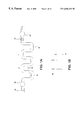
- FIG. 14 is a sample analysis instrument for use with a fluidic cartridge.
- FIG. 1 shows the flow system contained within the cartridge of this invention.
- cartridge is used herein for a fluidic device which is preferably, but not necessarily, disposable and which can be coupled with measurement, pumping, electronic, fluidic or other apparatus. It includes sample inlet 10 , convoluted sample storage channel 20 , resuspension pump interface 40 , sample analysis region 30 and valve interface 50 .
- the flow system is preferably a microfluidic flow system.
- microfluidic channel is used herein for fluid elements dimensioned so that flow therein is substantially laminar. In a laminar flow system turbulence is negligible.
- the width of the channel is less than 2000 ⁇ m and the depth of the channel is less than 300 ⁇ m.
- the dimension must be greater than the largest particle dimension, typically greater than 25 ⁇ m.
- the sample inlet has an inlet shut-off interface to prevent the loaded sample from leaking out of the cartridge.
- the sample inlet comprises a septum.
- a hypodermic needle is used to inject the sample through the septum.
- the septum forms a shut-off to keep the sample in the flow system.
- the sample inlet can be a non-sealing inlet such as a capillary or a channel which mates with a sample conduit. If the inlet does not have an integral shut-off interface, it can be combined with a separate valve interface.
- the resuspension pump interface is used for reconstituting a sedimented sample following stop flow or storage.
- the pump can provide continuous or reversible flow.
- continuous flow resuspension the leading edge and trailing edge of the sample storage segment must be discarded, but the sample segment in the middle is resuspended to a homogeneous mixture identical to the original sample.
- Significant operating parameters are the resuspension flow rate and the resuspension time.
- Reversible flow resuspension uses a plurality of dispense/aspirate cycles. In this protocol, in each cycle the sedimented sample is swept through the channel in dispense mode and then swept back in aspirate mode.
- the swept volume is typically 1-4 periods of the spatially periodic channel.
- the aspirated volume is typically equal to the dispensed volume.
- the significant operating parameters are the resuspend swept volume, the number of resuspension cycles and the resuspension flow rate.
- the resuspension parameters are specific to the particle laden fluid under consideration and the geometry ofthe storage channel. Suitable resuspension flow rates and times can be calculated or determined empirically.
- the critical wall shear stress, ⁇ crit for cell suspension maintenance is estimated to be 0.14 Pa.
- Eq. 1 for greater channel dimensions the critical flow rate is greater.
- the critical flow rate is 0.008 ⁇ l/s.
- the critical flow rate is 2.8 ⁇ l/s.
- valves and pumps of this invention can be entirely incorporated in the cartridge, or the cartridge can include only valve and pump interfaces, and the remainder of the valve and pump mechanisms can be external to the cartridge.
- a pump (valve) comprises a pump (valve) interface and a pump (valve) mechanism.
- the interface is that portion which is directly connected to flow elements, and the mechanism is the exterior portion.
- the cartridge can be inserted in measurement apparatus comprising valve and pump mechanisms. Upon loading the cartridge in the apparatus, the valve and pump mechanisms engage the valve and pump interfaces.
- the valves can be either normally open or normally closed. They can be manually or automatically actuated.
- FIG. 2 Sedimentation in convoluted storage channels is illustrated in FIG. 2 .
- the channels contain a plurality of particle capture regions so that the particles cannot aggregate in a single clump.
- the illustrated convoluted channels are spatially periodic.
- the term spatially periodic channel is used herein for a channel having a substantially constant number of particle capture regions per unit volume. This facilitates recreating a homogeneous sample upon resuspension.
- the illustrated embodiments are spatially periodic in a conventional geometric sense, having repeating units of length ⁇ . Alternatively, the channel can be randomly convoluted but nonetheless have a substantially constant number of particle capture regions per unit volume.
- the channel of FIG. 2A is suitable for storing particle-containing liquid in the illustrated orientation. If it were aligned along the channel axis, i.e. rotated so that the inlet and outlet were at the top, all of the particles would accumulate in the bottom capture region and would be difficult to resuspend uniformly.
- This type of spatially periodic channel is referred to herein as anisotropic because the suitability for storage depends on orientation. This anisotrophy can be disadvantageous. To prevent clumping the cartridge must be carefully handled to ensure that it is never aligned along the channel axis.
- the channel of FIG. 2B can be used for storage at any orientation and is thus referred to herein as an isotropic storage channel. Isotropic channels are preferred because it is not necessary to maintain a particular orientation during handling. Further examples of isotropic spatially periodic channels are shown in FIG. 3 .
- the channel of FIG. 3A has the same structure as the channel of FIG. 2B but with more repeated units.
- the channel of FIG. 3B is similar but with rounded comers. This can be advantageous for manufacturing and assembly.
- the channels of FIGS. 3C and D are referred to as “omega” channels, angular in FIG. 3 C and rounded in FIG. 3 D. Omega channels are similar to the square wave channel of FIG.
- FIG. 3 shows a few examples of storage channels; numerous other isotropic spatially periodic channels can be utilized.
- square waves are used as a generic illustration of convoluted channels. Other embodiments may be preferred and in particular isotropic channels may be preferred.
- This invention also provides a structure containing an isotropic storage channel.
- the structure is any solid material with a channel formed therein.
- the structure can be a disposable cartridge or a permanently installed element of a measurement or reaction instrument. It can be a microscale channel dimensioned for laminar flow or a macroscale channel dimensioned for turbulent flow.
- One embodiment is a bioreactor wherein reagents, which can include cells, are incubated in the channel followed by resuspension of particles.
- FIG. 4A shows a cross-section of the valve in the open position and FIG. 4B shows the valve in the closed position.
- Channel 21 running orthogonal to the plane of the paper, has walls formed by sheet 162 B, and top and bottom formed by sheets 162 A and C.
- Elastic seal 51 fits within an opening in sheet 162 A.
- the fluid element containing sheets are sandwiched between upper cartridge case 130 and lower cartridge case 131 .
- the valve mechanism includes valve pin 150 which is made of a rigid material, for example metal or plastic. The valve pin is guided by an opening in upper case 130 . When actuated, the pin presses against seal 51 , which extrudes into the channel, thereby closing it.
- the channel itself is not pinched closed.
- the valve mechanism can be incorporated into the cartridge or it can be a separate element.
- Seal 51 is made of a deformable material such as silicone, urethane, natural rubber or other elastomers.
- the channel is formed with three separate sheets, 162 A-C; it can instead be formed in fewer than or in more than three sheets.
- the pinch valve of FIG. 4 is an example of a valve that can be used with the analysis cartridge. Other valves can instead be used.
- FIG. 5 An embodiment of resuspension pump interface 40 is shown in cross-section in FIG. 5 .
- Channel 22 A running orthogonal to the plane of the paper, has walls formed within sheet 164 B and bottom formed by sheet 164 C.
- Fluid communication via 22 is a circular hole in sheet 164 A allowing fluid flow from 140 to 22 A.
- Elastic seal 41 fits between sheet 164 A and upper cartridge case 130 .
- the pump mechanism includes cannula 140 , which is preferably connected to a syringe pump, not shown.
- the cannula can be inserted into seal 41 to introduce fluids into channel 22 A.
- the cannula can be essentially a needle with a polished tip to avoid damaging the seal.
- a fluid such as saline or water is it injected into the channel through the cannula, and it sweeps the sample fluid through the channel.
- the saline in extracted through the cannula.
- the syringe pump interface can be used both as a pump, one- or two-directional, and as a reagent inlet.
- the entire pump, interface and mechanism can be incorporated in the cartridge, or only the interface can be incorporated and the mechanism can be separate.
- the sample analysis region provides for detection by any means known in the art, for example optical, electrical, pressure sensitive, or flow sensitive detection. More then one analysis means can be employed in a single analysis region, for example optical and electrical.
- the cartridge can include an electrical interconnect.
- the cartridge can be electrically connected to electrical measuring apparatus.
- the cartridge can include a window positioned over the analysis region for optical coupling with measuring apparatus such as light sources and photodetectors.
- the windows can be inserted glass or, if the channel is formed in transparent sheets, the sheets themselves can serve as windows.
- the optical detection can be absorption, luminescent, fluorescent or scattering based.
- the cartridge can comprise a plurality of sample analysis regions.
- One of the analysis regions can provide a filling status gauge to indicate that the storage channel is filled. The gauge can be based on optical absorption measurement, pressure measurement, conductivity measurement, flow measurement or any measurement that indicates the presence of a fluid in the gauge. For absorption measurement, visual observation of filling status may be used.
- the analysis region is a flow cytometric analysis region.
- a sheath flow assembly is positioned along the analysis channel before the flow cytometric analysis region.
- FIGS. 6 and 7 illustrated a preferred embodiment of the sheath flow assembly.
- the assembly comprises seven sheets, 166 A-G, which are laminated together to form the fluidic elements of analysis cartridge 160 .
- the analysis channel comprising core stream channel 26 and sheathed stream channel 27 , is connected to the convoluted storage channel (not shown).
- first and second sheath fluid channels jointly labeled as element 72 (FIG. 7 D), are positioned on either side of and converge with channel 26 .
- the diameter of the sheathed portion is greater than the core portion of the analysis channel.
- the sheath fluid channels extend into layers 166 C and E, and are labeled as elements 75 and 76 .
- the sheath fluid channels provide hydrodynamic focusing of particles in channel 27 in the widthwise direction.
- Upper and lower sheath fluid chambers 73 and 74 are formed in sheets 166 B and F. When assembled, they are positioned above and below and converge with channel 26 .
- the sheath fluid chambers provide hydrodynamic focusing in the depthwise direction. To minimize layer to layer depthwise discontinuities in the region where the sheath fluid channels and chambers converge with the analysis channel, the downstream edges are staggered.
- the edge of channels 75 and 76 are slightly to the right of the edge of channel 72 .
- Sheath fluid is conducted to the sheath flow assembly through sheath fluid channel 71 (FIG. 7 B). Vias 77 in sheets 166 C-E connect channel 71 with the sheath fluid chambers. The sheath fluid chambers communicate fluid to the sheath fluid channels. In typical hydrodynamic focusing operation, the ratio of sheath flow to core stream 26 flow is around 130:1.
- the analysis region 30 includes window recesses 31 and 32 in sheets 166 C and E positioned above and below the focused sample.
- the window recesses accommodate glass inserts.
- sheets 166 C and E can themselves serve as windows.
- optical clearing holes 33 allow optical access to the analysis region.
- the sheets in FIG. 7 are sandwiched between an upper case and a lower case. Layers 166 A and G can be incorporated in the case.
- the illustrated embodiment also includes waste storage container 100 . It is connected with flow channel 27 through vias 101 and to a case mounted storage container through vias 102 .
- sheath flow assembly has been illustrated.
- Other sheath flow assemblies known in the art can be utilized, for example U.S. Pat. No. 4,983,038. Because this sheath flow assembly of the present invention provides both widthwise and depthwise hydrodynamic focusing, geometric focusing is not required.
- the analysis channel can decrease in width and/or depth and in a downstream direction.
- Two-dimensional hydrodynamic focusing can also be achieved using the device of U.S. patent application Ser. No. 08/823,747, filed Mar. 26, 1997.
- the flow channel can be constricted in the analysis region to provide single file particles, as described in single file, as described in U.S. Pat. No. 5,726,751.
- sample analysis region is an absorption analysis region.
- the optical path length, i.e. the channel depth, in the absorption measurement region is increased.
- the effective illumination area of the detection region can be increased by increasing the channel width.
- This balance can be determined for a specific assay, a specific set of light sources, detectors and optics, and the required accuracy and resolution.
- the cartridge can also include an inlet for mixing a reagent with the sample fluid prior to sample analysis, as shown in FIG. 8 .
- reagent refers to any fluid that joins the sample fluid. It can be, for example, a diluent, a lysing agent, an indicator dye, a fluorescent compound, a fluorescent standard bead for flow cytometric calibration, or a reporter bead for flow cytometric measurement (U.S. Pat. No. 5,747,349).
- reagent channel 80 joins analysis channel 24 .
- the reagent channel is connected to pump interface 40 A and reagent inlet 60 .
- the pump and the inlet are combined in a syringe pump.
- the cartridge includes valve interface 50 to separate the storage channel from the reagent inlet.
- the flow channels are microchannels having laminar flow therein, mixing between the reagent and the sample is predominantly diffusional mixing.
- the streams can join in side-by-side flow, as described in U.S. Pat. No. 5,716,852 and U.S. Ser. No. 08/829,679 filed Mar. 31, 1997, or in a layered flow for more rapid mixing, as described in U.S. Pat. No. 5,972,718 issued Oct. 26, 1999, and U.S. Ser. No. 08/938,585 filed Sep. 26, 1997.
- a mixing channel can be included, as shown in FIG. 9 .
- Mixing channel 90 is positioned between the reagent inlet and the analysis region.
- mixing channel 90 is selected to allow mixing and reaction between the sample and reagent streams.
- the mixing channel can be convoluted in order to achieve the desired time delay within a compact space.
- active mixing methods can be employed, including ultrasonic, mechanical, sonic, flow induced, etc.
- FIG. 10 shows the effect of channel geometry on gravitational mixing.
- a square wave channel is illustrated in FIG. 10 A.
- the particle-containing sample stream enters mixing channel 90 through channel 24 and reagent stream enters through channel 80 .
- the sample stream is gravitationally above the reagent stream and particles tend to settle into the reagent stream.
- this is reversed and particles settle back into the sample stream.
- This reversal of top and bottom for the sample stream and reagent stream can be used more effectively in an isotropic channel as illustrated in FIG. 10 B.
- a spatially periodic isotropic channel the gravitational top and bottom of the channel interchange within each repeating unit. This counteracts the effect of gravity on the particles in the sample stream.
- the isotropic spatially periodic channel is therefore useful for sedimentation mitigation as well as sedimentation resuspension.
- the cartridge can provide for more than one analysis region, in series or in parallel. Multiple parallel analysis regions are illustrated schematically in FIG. 11 .
- the device of FIG. 11 comprises sample inlet 10 , storage channel 20 , resuspension pump interface PI 1 (Pump Interface 1 ), and analysis regions 30 A-C.
- PI 1 Pulp Interface 1
- analysis regions 30 A-C At junctions J 1 , J 3 , J 5 , J 6 and at the end of the storage channel, fluid from the sample storage channel can be directed to analysis channels 24 A-D and to waste storage container 100 .
- the resuspension pump is fluidically connected to the storage channel in the middle ofthe channel rather than at the beginning ofthe channel 1 .
- the sample segment between J 1 and J 3 flows through valve V 3 for analysis
- the sample segment between J 3 and J 5 flows through valve V 2 for analysis
- the segment between J 5 and J 6 flows through valve V 1 for analysis.
- the cartridge further includes pump interfaces PI 2 -PI 5 , valve interfaces V 1 -V 5 , reagent channels 80 A-C, sheath flow assembly 70 , waste storage container 100 , and vents 110 A-C.
- the sample inlet is a septum
- the pump interfaces are syringe pump interfaces
- the valve interfaces are pinch valve interfaces.
- the vents are made of gas permeable plugs having a reduced permeability when wet.
- the storage and mixing channels are illustrated as square waves but are preferably isotropic spatially periodic channels.
- the sheath flow assembly is preferably as illustrated in FIGS. 6 and 7.
- Analysis region 30 C is a filling status gauge providing visual indication of proper sample load.
- Analysis region 30 A is an absorption measurement region, optically coupled with measurement apparatus comprising both a green and a blue LED and a photodetector.
- Analysis region 30 B is a flow cytometric analysis region optically coupled with a measurement apparatus comprising a diode laser and a plurality of photodetectors at various optical axis and collection cone angles.
- the cartridge of FIG. 11 can be used for hematology.
- a single cartridge can determine the red cell count, the total hemoglobin, and the white cell count and characterization.
- the analysis requires only 15 ⁇ l of sample, and the waste fluid is contained within the cartridge for safe operation and disposability.
- the sample is loaded into the storage channel through inlet 10 .
- the potentially contaminated leading edge ofthe sample flows in bypass channel 25 (FIG. 12 ), having a larger diameter than channel 20 . Air in the channel escapes through vent 110 A.
- the next segment of the sample fills the storage channel.
- Valve V 4 is open and the sample flows to filling status indicator 30 C. Vent 110 C allows air to escape during sample loading. Excess sample flows into sample load bypass storage 115 .
- the cartridge can be stored or transported prior to analysis.
- the cartridge is inserted into a measurement instrument having a cartridge holder and valve and pump mechanisms, which engage the valve and pump interfaces on the cartridge.
- the pump mechanisms comprise syringe pumps wherein the syringes are filled with reagents.
- the syringe connected to PI 1 is filled with an inert driving fluid
- the syringe connected to PI 2 is filled with diluent
- the syringe connected to PI 3 is filled with a soft lysing agent
- the syringe connected to PI 4 is filled with a Drabkin lysing reagent
- the syringe connected to PI 5 is filled with a sheath fluid.
- the procedure for operating the analysis cartridge of FIG. 11 for hematology is outlined in Tables 1-3. For each time interval from t 1 through t 17 , Table 1 describes the procedure, Table 2 gives the elapsed time, and Table 3 gives the status of valves and pumps fluidically connected to the cartridge and the status of optical measurement apparatus optically connected to the cartridge.
- Table 1 For each time interval from t 1 through t 17 , Table 1 describes the procedure, Table 2 gives the elapsed time, and Table 3 gives the status of valves and pumps fluidically connected to the cartridge and the status of optical measurement apparatus optically connected to the cartridge.
- air is purged from resuspension pump interface PI 1 through valve V 5 into waste storage container 100 .
- t 2 the reagent and sheath fluid channels are purged and wet.
- the optical path in absorption measurement region 30 A is calibrated using the blue LED.
- the total hemoglobin sample segment between J 1 and J 3 is resuspended by alternating dispense and aspirate cycles using P 1 .
- the total hemoglobin assay is performed by mixing the blood with Drabkin reagent to lyse the red blood cells, and measuring the absorption in analysis region 30 A. To create a bubble-free mixture in the analysis region, air is purged from channels 24 A and 80 A. Preferably the sample fluid and the reagent reach J 2 simultaneously.
- Mixing channel 90 A is designed to allow formation of the cyanomethahemoglobin complex.
- flow cytometric analysis is performed.
- time intervals t 6 , t 7 and t 8 the channels used in flow cytometric analysis are purged.
- sheath fluid is pumped through the region during the purge. The sheath flow is set to a low ratio to minimize fluid accumulation in the waste storage container during priming stages.
- t 9 the RBC sample segment between J 5 and J 6 is resuspended.
- t 10 and t 11 the optical measuring apparatus is aligned and the flow is stabilized.
- t 12 and t 13 the RBC flow cytometric assay is performed.
- t 14 the WBC sample segment between J 3 and J 5 is resuspended.
- t 15 a soft lysing reagent is added to the sample and time is allowed for mixing and reaction in mixing channel 90 B.
- t 16 and t 17 the WBC assay is performed. The total elapsed time is 1.75 minutes. Following analysis, the cartridge is disposed of.
- FIGS. 13A-G show the seven sheets, 167 A-G, which are laminated together to form cartridge 160 shown in FIG. 12 .
- This is a three-dimensional fluidic structure wherein channels in different layers appear to overlap in FIG. 12 but are in fact separated by sheets 167 C and E. Vias in intervening sheets connect flow elements in different layers. Three-dimensional structures can be more compact and rugged than two-dimensional structures. Registry of the laminated sheets to the case is accomplished with holes 170 in the sheets. The case has pins that fit within holes 170 .
- the cartridge is inserted into a measurement instrument including a cartridge holder.
- the outer case of the cartridge (not shown) has alignment markings thereon for optical and fluidic alignment with the measurement apparatus.
- the alignment markings are kinematic alignment markings comprising a pit, a groove and a flat.
- the cartridge holder has corresponding pins.
- the shape ofthe cartridge is designed for engagement with the cartridge holder, and thus in itself comprises an alignment marking.
- Sample is introduced through inlet 10 and stored in channel 20 .
- the sample leading edge flows into bypass channel 25 .
- the bypass channel is fluidically connected to a case-mounted waste storage container (not shown).
- Syringe pump interfaces 40 A-E and pinch valve interfaces 50 A-D (FIG. 13A) control sample management in the cartridge.
- the syringe pump interfaces are also reagent inlets.
- valve 50 D When valve 50 D is open sample flows through channel 24 D (FIG. 13F) to filling status gauge 30 C.
- For total hemoglobin assay lysing reagent is introduced through syringe pump interface 40 D and the mixture flows through analysis channel 24 A (FIG. 13D) to absorption analysis region 30 A.
- valve 50 A is opened, diluent is introduced through syringe pump interface 40 B, and the red blood cells are hydrodynamically focused in sheath flow assembly 70 and counted in flow cytometric analysis region 30 B.
- valve 50 B is opened, a soft lysing agent, which masks red blood cells and platelets, is introduced through syringe pump interface 40 C, mixing and reaction occur in mixing channel 90 (FIG. 13 B), the sample is hydrodynamically focused in sheath flow assembly 70 and analyzed in flow cytometric analysis region 30 B.
- Waste fluid from all three analysis regions flows into waste storage container 100 (FIG. 13 F), which is fluidically connected with a case-mounted storage container having a vent therein. This waste storage container is a channel. It can alternatively or in addition be a fixed or expandable reservoir.
- storage channel 20 and mixing channel 90 are formed in sheet 167 D.
- peninsulas of sheet material remain around the channels.
- the peninsulas are not well supported and can flop around during laminate assembly.
- a less floppy channel can be formed using two or more layers, with alternating loops of the channel formed in different layers.
- the cartridge has been illustrated with particular mixing and measurement configurations. It can also provide filtering, diffusion based filtering as described in U.S. Pat. No. 5,932,100 issued Aug. 3, 1999, simultaneous particle separation and chemical reaction as described in U.S. Ser. No. 08/938,585 filed Sep. 26, 1997, valveless microswitching as described in U.S. Pat. No. 5,726,404, diffusion-based chemical sensing as described in U.S. Pat. No. 5,716,852, U.S. Pat. No. 5,948,684 issued Sep. 7,1999, and adsorption-enhanced differential extraction as described in U.S. Pat. No. 5,971,158 issued Oct. 26, 1999.
- the channel can also include fluidic elements for extraction, electrophoresis, electrochemical reactions, chromatography and ion exchange reactions.
- the cartridge can be fabricated from any moldable, machinable or etchable material.
- machining as used herein includes printing, stamping, cutting and laser ablating.
- the cartridge can be formed in a single sheet, in a pair of sheets sandwiched together, or in a plurality of sheets laminated together.
- sheet refers to any solid substrate, flexible or otherwise.
- the channels can be etched in a silicon substrate and covered with a cover sheet, which can be a transparent cover sheet.
- the channel walls are defined by removing material from a first sheet and the channel top and bottom are defined by laminating second and third sheets on either side of the first sheet. Any of the layers can contain fluid channels.
- the channel is simply a hole (or fluid via) to route the fluid to the next fluid laminate layer.
- Any two adjacent laminate layers may be permanently bonded together to form a more complex single part.
- Often fluidic elements that have been illustrated in two separate layers can be formed in a single layer.
- Each layer of a laminate assembly can be formed of a different material.
- the layers are preferably fabricated from substantially rigid materials.
- a substantially rigid material is inelastic, preferably having a modulus of elasticity less than 1,000,000 psi, and more preferably less than 600,000 psi.
- Substantially rigid materials can still exhibit dramatic flexibility when produced in thin films.
- substantially rigid plastics include cellulose acetate, polycarbonate, methylmethacrylate and polyester.
- Metals and metal alloys are also substantially rigid. Examples include steels, aluminum, copper, etc. Glasses, silicon and ceramics are also substantially rigid.
- material is removed to define the desired structure.
- the sheets can be machined using a laser to ablate the material from the channels.
- the material can be removed by traditional die cutting methods. For some materials chemical etching can be used.
- the negative of the structure desired can be manufactured as a mold and the structure can be produced by injection molding, vacuum thermoforming, pressure-assisted thermoforming or coining techniques.
- the individual layers, assemblies of layers, or molded equivalents are bonded together using adhesives or welding.
- mechanical compression through the use of fasteners such as screws, rivets and snap-together assembly can be used to seal adjacent layers.
- Layers can be assembled using adhesives in the following ways.
- a rigid contact adhesive for example, 3M1151
- a solvent release adhesive may be used to chemically bond two adjacent players.
- An ultraviolet curing adhesive (for example, Loctite 3107) can be used to join adjacent layers when at least one layer is transparent in the ultraviolet.
- Precision applied epoxies, thermoset adhesives, and thermoplastic adhesives can also be used. Dry coatings that can be activated to bond using solvents, heat or mechanical compression can be applied to one or both surfaces.
- Layers can be welded together. For welding the layers preferably have similar glass transition temperatures and have mutual wetting and solubility characteristics. Layers can be welded using radio frequency dielectric heating, ultrasonic heating or local thermal heating.
- the device of FIGS. 12 and 13 was fabricated as follows. Layers 167 A and G were made of 4 mil mylar and layers 167 C and E were made of 2 mil mylar. Layers 167 B, D and F were made of 2 mil mylar with 3M1151 on both sides (4 mil inclusive).
- the adhesive had cover sheets thereon. With the cover sheets still on the adhesive, the sheets were laser ablated to machine flow elements therein. The cover sheets were removed and the individual laminate was assembled with the aid of an alignment jig.
- This invention further includes a sample analysis instrument for use with an analysis cartridge, in particular a hematology analysis cartridge.
- the instrument has a cartridge holder, a flow cytometric measuring apparatus positioned to be coupled with a flow cytometric measuring region on the cartridge, and a second measuring apparatus positioned to be coupled with a second measuring region on the cartridge.
- the flow cytometric measuring apparatus comprises a light source, preferably a laser, and at least one photodetector.
- the photodetectors can be positioned for measuring small angle scattering, large angle scattering or fluorescence.
- the apparatus can also include optical elements such as focusing and collection lenses, wavelength filters, dichroic mirrors and polarizers.
- the second measuring apparatus can be any measuring apparatus including optical, electrical, pressure sensitive and flow sensitive apparatus.
- Absorption measuring apparatus comprising a light source and a photodetector is preferred.
- the light source is positioned on a first side of the cartridge holder and the photodetector is positioned on the opposite side.
- a measurement instrument is shown schematically in FIG. 14 . It comprises cartridge holder 190 , flow cytometric measurement apparatus 180 B and absorption measurement apparatus 180 A. Cartridge 160 , shown in phantom, slides into the cartridge holder. The measurement apparati are positioned to be optically coupled with flow cytometric analysis region 30 B and absorption analysis region 30 A.
- This instrument also includes pump and valve mechanism manifold 141 .
- the pump mechanisms are syringe pumps which couple to pump interfaces on the cartridge via cannulas 140 .
- the manifold can also include reagent reservoirs to refill the syringe pumps for multiple assays.
- the valve mechanisms activate valve pins 150 , which couple to valve interfaces on the cartridge.
- the cartridge holder has alignment markings thereon to mate with corresponding markings on the cartridge.
- the alignment markings can be the shape of the holder, protruding pins, notches, rods, kinematic mounts, two stage kinematic mounts as described in U.S. Pat. No. 5,748,827 issued May 5, 1998, or any other feature that facilitates positioning of the cartridge.
- the instrument can include optical steering elements, such as mirrors, to align the measuring apparatus with the analysis region.
- the analysis instrument can further include valve and pump mechanisms which couple with valve and pump interfaces on the cartridge.
- t1 Purge air from PI1 through valve V5.
- t2 Purge air and wet delivery lines from PI2 to J7; PI3 to J7; PI4 to J2; and PI5 to J8 t3 THB optical path calibration using 430 nm blue LED and Drabkin reagent absorbtion.
- t4 THB Sample segment resuspension t5 Total hemaglobin assay; purge of air from J1 to J2 & uniform mixing of sample + Drabkin & creation of a bubble free mixture in flow cell. Time allowed for the creation of the Cyanomethahemaglobin complex.
- t6 RBC sample segment mis/air purge from J6 through J9 & J7 to J8.
- Sheath pump is set to a low ratio, about 5:1 in order to protect optical surfaces of the cytometer section.
- Sheath pump is set to a low ratio, about 5:1 in order to protect optical surfaces of the cytometer section.
- t9 RBC sample segment resuspension t10 Beam steering/optical targeting.
- t11 RBC assay flow stabilization algorithm based on mean pulse frequency PID feedback control
- t13 Second RBC assay (if required) t14 WBC sample segment resuspension t15 WBC assay flow stabilization and 15 second time delay.
- t17 Second WBC assay if required
Abstract
Description

| TABLE 1 |
| Time Interval Description |
| t1 | Purge air from PI1 through valve V5. |
| t2 | Purge air and wet delivery lines from PI2 to J7; PI3 to J7; PI4 to J2; |
| and PI5 to J8 | |
| t3 | THB optical path calibration using 430 nm blue LED and Drabkin |
| reagent absorbtion. | |
| t4 | THB Sample segment resuspension |
| t5 | Total hemaglobin assay; purge of air from J1 to J2 & uniform mixing |
| of sample + Drabkin & creation of a bubble free mixture in flow cell. | |
| Time allowed for the creation of the Cyanomethahemaglobin | |
| complex. | |
| t6 | RBC sample segment mis/air purge from J6 through J9 & J7 to J8. |
| Sheath pump is set to a low ratio, about 5:1 in order to protect optical | |
| surfaces of the cytometer section. | |
| t7 | WBC sample segment mis/air purge from J3 through J4 & J7 to J8. |
| Sheath pump is set to a low ratio, about 5:1 in order to protect optical | |
| surfaces of the cytometer section. | |
| t8 | J7 junction purge. Purge air from the region around J7 through the |
| cytometer to waste. | |
| t9 | RBC sample segment resuspension |
| t10 | Beam steering/optical targeting. |
| t11 | RBC assay flow stabilization algorithm based on mean pulse |
| frequency PID feedback control | |
| t12 | RBC assay. |
| t13 | Second RBC assay (if required) |
| t14 | WBC sample segment resuspension |
| t15 | WBC assay flow stabilization and 15 second time delay. |
| t16 | WBC assay. |
| t17 | Second WBC assay (if required) |
| TABLE 2 | |||||||||||||||||
| Time | |||||||||||||||||
| interval | t1 | t2 | t3 | t4 | t5 | t6 | t7 | t8 | t9 | t10 | t11 | t12 | t13 | t14 | t15 | t16 | t17 |
| Interval | 1 | 3 | 2 | 3 | 10 | 2 | 2 | 1 | 3 | 5 | 4 | 4 | 3 | 1.6 | 17 | 22 | 22 |
| time(s) | |||||||||||||||||
| Elapsed | 1 | 4 | 6 | 9 | 19 | 21 | 23 | 24 | 27 | 32 | 36 | 40 | 43 | 45 | 62 | 83 | 105 |
| time(s) | |||||||||||||||||
| Elapsed | 0.02 | 0.07 | 0.10 | 0.15 | 0.32 | 0.35 | 0.38 | 0.40 | 0.45 | 0.53 | 0.60 | 0.67 | 0.72 | 0.74 | 1.03 | 1.39 | 1.75 |
| time | |||||||||||||||||
| (min) | |||||||||||||||||
| TABLE 3 |
| Resource Status |
| Time interval | t1 | t2 | t3 | t4 | t5 | t6 | t7 | t8 | t9 | t10 | t11 | t12 | t13 | t14 | t15 | t16 | t17 |
| Resuspension pump, P1D | X | X | X | X | X | X | X | X | X | X | X | X | X | X | |||
| (dispense) | |||||||||||||||||
| Resuspension pump, P1A | X | X | X | X | X | X | X | X | X | X | X | X | X | X | |||
| (asperiate) | |||||||||||||||||
| Diluent pump, P2 | X | X | X | X | X | X | X | X | X | ||||||||
| Soft Lyse pump, P3 | X | X | X | X | X | X | |||||||||||
| THB pump, P4 | X | X | X | X | |||||||||||||
| Sheath pump, P5 | X | X | X | X | X | X | X | X | X | X | X | X | X | ||||
| RBC Valve, V1 | C1 | O | C | C | C | O | C | O | O | O | O | O | O | O | C | C | C |
| WBC Valve, V2 | C | O | C | C | C | C | O | O | C | C | C | C | C | C | O | O | O |
| THB Valve, V3 | C | O | C | O | O | C | C | C | C | C | C | C | C | C | C | C | C |
| Waste Isolation Valve, V4 | C | C | C | C | C | C | C | C | C | C | C | C | C | C | C | C | C |
| Sample delivery purge, V5 | O | C | C | C | C | C | C | C | C | C | C | C | C | C | C | C | C |
| Beam Steering Motor, M1 | X | ||||||||||||||||
| Beam Steering Motor, M2 | X | ||||||||||||||||
| Diode laser | X | X | X | X | X | X | X | X | |||||||||
| Green LED | X | ||||||||||||||||
| Blue LED | X | ||||||||||||||||
| 1C = Closed, O = Open | |||||||||||||||||
Claims (11)
Priority Applications (2)
| Application Number | Priority Date | Filing Date | Title |
|---|---|---|---|
| US09/428,839 US6656431B2 (en) | 1998-05-18 | 1999-10-28 | Sample analysis instrument |
| US09/723,823 US6830729B1 (en) | 1998-05-18 | 2000-11-28 | Sample analysis instrument |
Applications Claiming Priority (2)
| Application Number | Priority Date | Filing Date | Title |
|---|---|---|---|
| US8069198A | 1998-05-18 | 1998-05-18 | |
| US09/428,839 US6656431B2 (en) | 1998-05-18 | 1999-10-28 | Sample analysis instrument |
Related Parent Applications (1)
| Application Number | Title | Priority Date | Filing Date |
|---|---|---|---|
| US8069198A Division | 1998-05-18 | 1998-05-18 |
Related Child Applications (1)
| Application Number | Title | Priority Date | Filing Date |
|---|---|---|---|
| US09/723,823 Continuation US6830729B1 (en) | 1998-05-18 | 2000-11-28 | Sample analysis instrument |
Publications (2)
| Publication Number | Publication Date |
|---|---|
| US20030152487A1 US20030152487A1 (en) | 2003-08-14 |
| US6656431B2 true US6656431B2 (en) | 2003-12-02 |
Family
ID=22159002
Family Applications (7)
| Application Number | Title | Priority Date | Filing Date |
|---|---|---|---|
| US09/428,804 Expired - Lifetime US6712925B1 (en) | 1998-05-18 | 1999-10-28 | Method of making a liquid analysis cartridge |
| US09/428,807 Expired - Lifetime US6576194B1 (en) | 1998-05-18 | 1999-10-28 | Sheath flow assembly |
| US09/428,801 Expired - Lifetime US6537501B1 (en) | 1998-05-18 | 1999-10-28 | Disposable hematology cartridge |
| US09/428,839 Expired - Lifetime US6656431B2 (en) | 1998-05-18 | 1999-10-28 | Sample analysis instrument |
| US09/428,793 Abandoned US20030096430A1 (en) | 1998-05-18 | 1999-10-28 | Method of storing a particle-containing liquid |
| US09/688,055 Expired - Lifetime US6852284B1 (en) | 1998-05-18 | 2000-10-13 | Liquid analysis cartridge |
| US11/195,328 Expired - Fee Related US7226562B2 (en) | 1998-05-18 | 2005-08-02 | Liquid analysis cartridge |
Family Applications Before (3)
| Application Number | Title | Priority Date | Filing Date |
|---|---|---|---|
| US09/428,804 Expired - Lifetime US6712925B1 (en) | 1998-05-18 | 1999-10-28 | Method of making a liquid analysis cartridge |
| US09/428,807 Expired - Lifetime US6576194B1 (en) | 1998-05-18 | 1999-10-28 | Sheath flow assembly |
| US09/428,801 Expired - Lifetime US6537501B1 (en) | 1998-05-18 | 1999-10-28 | Disposable hematology cartridge |
Family Applications After (3)
| Application Number | Title | Priority Date | Filing Date |
|---|---|---|---|
| US09/428,793 Abandoned US20030096430A1 (en) | 1998-05-18 | 1999-10-28 | Method of storing a particle-containing liquid |
| US09/688,055 Expired - Lifetime US6852284B1 (en) | 1998-05-18 | 2000-10-13 | Liquid analysis cartridge |
| US11/195,328 Expired - Fee Related US7226562B2 (en) | 1998-05-18 | 2005-08-02 | Liquid analysis cartridge |
Country Status (5)
| Country | Link |
|---|---|
| US (7) | US6712925B1 (en) |
| EP (1) | EP1046032A4 (en) |
| AU (1) | AU3771599A (en) |
| CA (1) | CA2320296A1 (en) |
| WO (1) | WO1999060397A1 (en) |
Cited By (46)
| Publication number | Priority date | Publication date | Assignee | Title |
|---|---|---|---|---|
| US20020037239A1 (en) * | 2000-09-22 | 2002-03-28 | Fuji Photo Film Co., Ltd. | Quantitative suction tip and quantitative suction apparatus |
| US20020168780A1 (en) * | 2001-02-09 | 2002-11-14 | Shaorong Liu | Method and apparatus for sample injection in microfabricated devices |
| US20030015429A1 (en) * | 1999-02-02 | 2003-01-23 | Caliper Technologies Corp. | Methods, devices and systems for characterizing proteins |
| US20050032238A1 (en) * | 2003-08-07 | 2005-02-10 | Nanostream, Inc. | Vented microfluidic separation devices and methods |
| US20050031494A1 (en) * | 2000-06-28 | 2005-02-10 | 3M Innovative Properties Company | Sample processing devices and carriers |
| US20050145046A1 (en) * | 2003-12-12 | 2005-07-07 | Boehringer Ingelheim Microparts Gmbh | Sampling means and system for testing a sample liquid |
| US20050284213A1 (en) * | 2004-06-29 | 2005-12-29 | Nanostream, Inc. | Sealing interface for microfluidic device |
| US7226562B2 (en) * | 1998-05-18 | 2007-06-05 | University Of Washington | Liquid analysis cartridge |
| US7417418B1 (en) | 2005-06-14 | 2008-08-26 | Ayliffe Harold E | Thin film sensor |
| WO2009045343A1 (en) | 2007-09-29 | 2009-04-09 | El Spectra, Llc | Instrumented pipette tip |
| US7520164B1 (en) | 2006-05-05 | 2009-04-21 | E.I. Spectra, Llc | Thin film particle sensor |
| US20090272179A1 (en) * | 2006-05-05 | 2009-11-05 | E.I. Spectra, Llc | Thin film particle sensor |
| US20090324447A1 (en) * | 2000-12-28 | 2009-12-31 | John Brann | Multi column chromatography system |
| US7767447B2 (en) | 2007-06-21 | 2010-08-03 | Gen-Probe Incorporated | Instruments and methods for exposing a receptacle to multiple thermal zones |
| US20100288941A1 (en) * | 2007-11-27 | 2010-11-18 | Ayliffe Harold E | Fluorescence-based pipette instrument |
| US7932090B2 (en) | 2004-08-05 | 2011-04-26 | 3M Innovative Properties Company | Sample processing device positioning apparatus and methods |
| US20110162439A1 (en) * | 2006-02-02 | 2011-07-07 | Ayliffe Harold E | Reusable thin film particle sensor |
| US20110189714A1 (en) * | 2010-02-03 | 2011-08-04 | Ayliffe Harold E | Microfluidic cell sorter and method |
| USD645971S1 (en) | 2010-05-11 | 2011-09-27 | Claros Diagnostics, Inc. | Sample cassette |
| US8097471B2 (en) | 2000-11-10 | 2012-01-17 | 3M Innovative Properties Company | Sample processing devices |
| US8182635B2 (en) | 2008-04-07 | 2012-05-22 | E I Spectra, LLC | Method for manufacturing a microfluidic sensor |
| US8329437B1 (en) | 2004-07-29 | 2012-12-11 | E.I. Spectra, Llc | Disposable particle counter cartridge |
| US8580569B2 (en) | 2010-04-16 | 2013-11-12 | Opko Diagnostics, Llc | Feedback control in microfluidic systems |
| WO2013184168A1 (en) | 2012-06-09 | 2013-12-12 | E.I. Spectra, Llc | Fluorescence flow cytometry |
| US8663583B2 (en) | 2011-12-27 | 2014-03-04 | Honeywell International Inc. | Disposable cartridge for fluid analysis |
| US8741234B2 (en) | 2011-12-27 | 2014-06-03 | Honeywell International Inc. | Disposable cartridge for fluid analysis |
| US8741235B2 (en) | 2011-12-27 | 2014-06-03 | Honeywell International Inc. | Two step sample loading of a fluid analysis cartridge |
| US8741233B2 (en) | 2011-12-27 | 2014-06-03 | Honeywell International Inc. | Disposable cartridge for fluid analysis |
| US8797527B2 (en) | 2011-08-24 | 2014-08-05 | Abbott Point Of Care, Inc. | Biologic fluid sample analysis cartridge |
| US8804105B2 (en) | 2012-03-27 | 2014-08-12 | E. I. Spectra, Llc | Combined optical imaging and electrical detection to characterize particles carried in a fluid |
| US9103760B2 (en) | 2012-06-09 | 2015-08-11 | E. I. Spectra, Llc | Fluorescence flow cytometry device and method |
| US9222623B2 (en) | 2013-03-15 | 2015-12-29 | Genmark Diagnostics, Inc. | Devices and methods for manipulating deformable fluid vessels |
| US9293311B1 (en) | 2006-02-02 | 2016-03-22 | E. I. Spectra, Llc | Microfluidic interrogation device |
| US9452429B2 (en) | 2006-02-02 | 2016-09-27 | E. I. Spectra, Llc | Method for mutiplexed microfluidic bead-based immunoassay |
| US9498778B2 (en) | 2014-11-11 | 2016-11-22 | Genmark Diagnostics, Inc. | Instrument for processing cartridge for performing assays in a closed sample preparation and reaction system |
| US9579651B2 (en) | 2009-12-18 | 2017-02-28 | Abbott Point Of Care, Inc. | Biologic fluid analysis cartridge |
| US9598722B2 (en) | 2014-11-11 | 2017-03-21 | Genmark Diagnostics, Inc. | Cartridge for performing assays in a closed sample preparation and reaction system |
| US9696252B2 (en) | 2005-10-19 | 2017-07-04 | Abbott Laboratories | Apparatus for performing counts within a biologic fluid sample |
| USD804682S1 (en) | 2015-08-10 | 2017-12-05 | Opko Diagnostics, Llc | Multi-layered sample cassette |
| US9873118B2 (en) | 2010-12-30 | 2018-01-23 | Abbott Point Of Care, Inc. | Biologic fluid analysis cartridge with sample handling portion and analysis chamber portion |
| US9957553B2 (en) | 2012-10-24 | 2018-05-01 | Genmark Diagnostics, Inc. | Integrated multiplex target analysis |
| US10005080B2 (en) | 2014-11-11 | 2018-06-26 | Genmark Diagnostics, Inc. | Instrument and cartridge for performing assays in a closed sample preparation and reaction system employing electrowetting fluid manipulation |
| US10495656B2 (en) | 2012-10-24 | 2019-12-03 | Genmark Diagnostics, Inc. | Integrated multiplex target analysis |
| US10578602B2 (en) | 2004-04-07 | 2020-03-03 | Abbott Laboratories | Disposable chamber for analyzing biologic fluids |
| USD881409S1 (en) | 2013-10-24 | 2020-04-14 | Genmark Diagnostics, Inc. | Biochip cartridge |
| US11952618B2 (en) | 2021-01-08 | 2024-04-09 | Roche Molecular Systems, Inc. | Integrated multiplex target analysis |
Families Citing this family (265)
| Publication number | Priority date | Publication date | Assignee | Title |
|---|---|---|---|---|
| US6541213B1 (en) | 1996-03-29 | 2003-04-01 | University Of Washington | Microscale diffusion immunoassay |
| CA2279574C (en) | 1997-01-31 | 2007-07-24 | The Horticulture & Food Research Institute Of New Zealand Ltd. | Optical apparatus |
| US6149867A (en) | 1997-12-31 | 2000-11-21 | Xy, Inc. | Sheath fluids and collection systems for sex-specific cytometer sorting of sperm |
| CA2632856C (en) * | 1998-06-24 | 2010-10-12 | Chen & Chen, Llc | Fluid sample testing system |
| US7045015B2 (en) | 1998-09-30 | 2006-05-16 | Optomec Design Company | Apparatuses and method for maskless mesoscale material deposition |
| US7108894B2 (en) * | 1998-09-30 | 2006-09-19 | Optomec Design Company | Direct Write™ System |
| US7938079B2 (en) * | 1998-09-30 | 2011-05-10 | Optomec Design Company | Annular aerosol jet deposition using an extended nozzle |
| US8110247B2 (en) * | 1998-09-30 | 2012-02-07 | Optomec Design Company | Laser processing for heat-sensitive mesoscale deposition of oxygen-sensitive materials |
| ATE508200T1 (en) * | 1999-02-23 | 2011-05-15 | Caliper Life Sciences Inc | SEQUENCING THROUGH INCORPORATION |
| FR2795518B1 (en) * | 1999-06-22 | 2001-12-21 | Biomerieux Sa | DEVICE FOR IMPLEMENTING AN ANALYSIS CARD, ANALYSIS CARD AND METHOD OF IMPLEMENTING THE SAME |
| US6858185B1 (en) * | 1999-08-25 | 2005-02-22 | Caliper Life Sciences, Inc. | Dilutions in high throughput systems with a single vacuum source |
| US7208265B1 (en) | 1999-11-24 | 2007-04-24 | Xy, Inc. | Method of cryopreserving selected sperm cells |
| WO2001064950A2 (en) * | 2000-02-28 | 2001-09-07 | Exact Sciences Corporation | Device and method for preparing a sample for analysis |
| US6561208B1 (en) * | 2000-04-14 | 2003-05-13 | Nanostream, Inc. | Fluidic impedances in microfluidic system |
| US6481453B1 (en) | 2000-04-14 | 2002-11-19 | Nanostream, Inc. | Microfluidic branch metering systems and methods |
| US6557427B2 (en) | 2000-05-24 | 2003-05-06 | Micronics, Inc. | Capillaries for fluid movement within microfluidic channels |
| US20060263888A1 (en) * | 2000-06-02 | 2006-11-23 | Honeywell International Inc. | Differential white blood count on a disposable card |
| US8518328B2 (en) * | 2005-12-27 | 2013-08-27 | Honeywell International Inc. | Fluid sensing and control in a fluidic analyzer |
| US7630063B2 (en) | 2000-08-02 | 2009-12-08 | Honeywell International Inc. | Miniaturized cytometer for detecting multiple species in a sample |
| US8071051B2 (en) * | 2004-05-14 | 2011-12-06 | Honeywell International Inc. | Portable sample analyzer cartridge |
| US7978329B2 (en) | 2000-08-02 | 2011-07-12 | Honeywell International Inc. | Portable scattering and fluorescence cytometer |
| US7215425B2 (en) | 2000-08-02 | 2007-05-08 | Honeywell International Inc. | Optical alignment for flow cytometry |
| US6970245B2 (en) | 2000-08-02 | 2005-11-29 | Honeywell International Inc. | Optical alignment detection system |
| US7471394B2 (en) | 2000-08-02 | 2008-12-30 | Honeywell International Inc. | Optical detection system with polarizing beamsplitter |
| US7420659B1 (en) * | 2000-06-02 | 2008-09-02 | Honeywell Interantional Inc. | Flow control system of a cartridge |
| US7641856B2 (en) * | 2004-05-14 | 2010-01-05 | Honeywell International Inc. | Portable sample analyzer with removable cartridge |
| US7242474B2 (en) | 2004-07-27 | 2007-07-10 | Cox James A | Cytometer having fluid core stream position control |
| US7130046B2 (en) | 2004-09-27 | 2006-10-31 | Honeywell International Inc. | Data frame selection for cytometer analysis |
| US6597438B1 (en) * | 2000-08-02 | 2003-07-22 | Honeywell International Inc. | Portable flow cytometry |
| US7016022B2 (en) | 2000-08-02 | 2006-03-21 | Honeywell International Inc. | Dual use detectors for flow cytometry |
| US7283223B2 (en) | 2002-08-21 | 2007-10-16 | Honeywell International Inc. | Cytometer having telecentric optics |
| US7262838B2 (en) | 2001-06-29 | 2007-08-28 | Honeywell International Inc. | Optical detection system for flow cytometry |
| US8383043B2 (en) * | 2004-05-14 | 2013-02-26 | Honeywell International Inc. | Analyzer system |
| ATE312680T1 (en) * | 2000-06-13 | 2005-12-15 | Element Six Pty Ltd | COMPOSITE DIAMOND BODY |
| US20010055546A1 (en) * | 2000-06-23 | 2001-12-27 | Weigl Bernhard H. | Method and apparatus for controlling fluid flow rate in a microfluidic circuit |
| CA2415055A1 (en) * | 2000-08-03 | 2002-02-14 | Caliper Technologies Corporation | Methods and devices for high throughput fluid delivery |
| AU2001281076A1 (en) | 2000-08-07 | 2002-02-18 | Nanostream, Inc. | Fluidic mixer in microfluidic system |
| US6890093B2 (en) | 2000-08-07 | 2005-05-10 | Nanostream, Inc. | Multi-stream microfludic mixers |
| WO2002014926A2 (en) | 2000-08-15 | 2002-02-21 | Nanostream, Inc. | Optical devices with fluidic systems |
| FR2813207B1 (en) * | 2000-08-28 | 2002-10-11 | Bio Merieux | REACTIONAL CARD AND USE OF SUCH A CARD |
| JP2004509335A (en) | 2000-09-18 | 2004-03-25 | ユニバーシティ オブ ワシントン | Microfluidic device for rotating operation of fluid interface between multiple flow streams |
| EP1327474A4 (en) * | 2000-09-22 | 2004-12-29 | Kawamura Inst Chem Res | Very small chemical device and flow rate adjusting method therefor |
| AU2002211325A1 (en) | 2000-09-29 | 2002-04-08 | Nanostream, Inc. | Microfluidic devices for heat transfer |
| AU2001296674A1 (en) * | 2000-10-06 | 2002-04-15 | Protasis Corporation | Microfluidic substrate assembly and method for making same |
| US6827095B2 (en) | 2000-10-12 | 2004-12-07 | Nanostream, Inc. | Modular microfluidic systems |
| US6536477B1 (en) | 2000-10-12 | 2003-03-25 | Nanostream, Inc. | Fluidic couplers and modular microfluidic systems |
| US6698454B2 (en) | 2000-11-02 | 2004-03-02 | Biacore Ab | Valve integrally associated with microfluidic liquid transport assembly |
| EP1331997B1 (en) | 2000-11-06 | 2004-06-16 | Nanostream, Inc. | Microfluidic flow control devices |
| US6644944B2 (en) | 2000-11-06 | 2003-11-11 | Nanostream, Inc. | Uni-directional flow microfluidic components |
| CA2468774C (en) | 2000-11-29 | 2015-06-30 | George E. Seidel | System for in-vitro fertilization with spermatozoa separated into x-chromosome and y-chromosome bearing populations |
| US7713687B2 (en) | 2000-11-29 | 2010-05-11 | Xy, Inc. | System to separate frozen-thawed spermatozoa into x-chromosome bearing and y-chromosome bearing populations |
| WO2002082057A2 (en) * | 2001-04-03 | 2002-10-17 | Micronics, Inc. | Split focusing cytometer |
| DE10117772C2 (en) | 2001-04-09 | 2003-04-03 | Advalytix Ag | Mixing device and mixing method for mixing small amounts of liquid |
| US6418968B1 (en) | 2001-04-20 | 2002-07-16 | Nanostream, Inc. | Porous microfluidic valves |
| US6814938B2 (en) | 2001-05-23 | 2004-11-09 | Nanostream, Inc. | Non-planar microfluidic devices and methods for their manufacture |
| US6743636B2 (en) * | 2001-05-24 | 2004-06-01 | Industrial Technology Research Institute | Microfluid driving device |
| US6811695B2 (en) | 2001-06-07 | 2004-11-02 | Nanostream, Inc. | Microfluidic filter |
| US6919046B2 (en) * | 2001-06-07 | 2005-07-19 | Nanostream, Inc. | Microfluidic analytical devices and methods |
| US7318912B2 (en) * | 2001-06-07 | 2008-01-15 | Nanostream, Inc. | Microfluidic systems and methods for combining discrete fluid volumes |
| US6981522B2 (en) | 2001-06-07 | 2006-01-03 | Nanostream, Inc. | Microfluidic devices with distributing inputs |
| US6729352B2 (en) | 2001-06-07 | 2004-05-04 | Nanostream, Inc. | Microfluidic synthesis devices and methods |
| US7077152B2 (en) | 2001-07-07 | 2006-07-18 | Nanostream, Inc. | Microfluidic metering systems and methods |
| US20030027225A1 (en) * | 2001-07-13 | 2003-02-06 | Caliper Technologies Corp. | Microfluidic devices and systems for separating components of a mixture |
| WO2003018198A1 (en) * | 2001-08-28 | 2003-03-06 | Gyros Ab | Retaining microfluidic microcavity and other microfluidic structures |
| US6919058B2 (en) * | 2001-08-28 | 2005-07-19 | Gyros Ab | Retaining microfluidic microcavity and other microfluidic structures |
| US20070071649A1 (en) * | 2001-09-10 | 2007-03-29 | Marcus R Kenneth | Capillary-channeled polymer fibers as stationary phase media for spectroscopic analysis |
| US6848462B2 (en) | 2001-12-06 | 2005-02-01 | Nanostream, Inc. | Adhesiveless microfluidic device fabrication |
| US6739576B2 (en) | 2001-12-20 | 2004-05-25 | Nanostream, Inc. | Microfluidic flow control device with floating element |
| US6877892B2 (en) | 2002-01-11 | 2005-04-12 | Nanostream, Inc. | Multi-stream microfluidic aperture mixers |
| US7261812B1 (en) | 2002-02-13 | 2007-08-28 | Nanostream, Inc. | Multi-column separation devices and methods |
| US6814859B2 (en) | 2002-02-13 | 2004-11-09 | Nanostream, Inc. | Frit material and bonding method for microfluidic separation devices |
| CA2472945A1 (en) | 2002-02-13 | 2003-08-21 | Nanostream, Inc. | Microfluidic separation column devices and fabrication methods |
| AU2003219829A1 (en) * | 2002-02-23 | 2003-09-09 | Nanostream, Inc. | Microfluidic multi-splitter |
| US7223371B2 (en) | 2002-03-14 | 2007-05-29 | Micronics, Inc. | Microfluidic channel network device |
| EP1352688A1 (en) * | 2002-04-09 | 2003-10-15 | Jean Brunner | Miniaturized sample holder |
| US9943847B2 (en) | 2002-04-17 | 2018-04-17 | Cytonome/St, Llc | Microfluidic system including a bubble valve for regulating fluid flow through a microchannel |
| JP2005529327A (en) * | 2002-06-11 | 2005-09-29 | ケムパック エイ/エス | Disposable cartridge for characterizing particles suspended in liquid |
| US20040021741A1 (en) * | 2002-07-30 | 2004-02-05 | Ottenheimer Thomas H. | Slotted substrate and method of making |
| EP2275533B9 (en) | 2002-08-01 | 2016-10-19 | Xy, Llc | Method of assessing sperm cells |
| US8486618B2 (en) | 2002-08-01 | 2013-07-16 | Xy, Llc | Heterogeneous inseminate system |
| US7855078B2 (en) | 2002-08-15 | 2010-12-21 | Xy, Llc | High resolution flow cytometer |
| US20040043506A1 (en) * | 2002-08-30 | 2004-03-04 | Horst Haussecker | Cascaded hydrodynamic focusing in microfluidic channels |
| US7169548B2 (en) | 2002-09-13 | 2007-01-30 | Xy, Inc. | Sperm cell processing and preservation systems |
| US20050048669A1 (en) * | 2003-08-26 | 2005-03-03 | Nanostream, Inc. | Gasketless microfluidic device interface |
| US6976384B2 (en) * | 2002-10-31 | 2005-12-20 | Nanostream, Inc. | Parallel detection chromatography systems |
| US7010964B2 (en) * | 2002-10-31 | 2006-03-14 | Nanostream, Inc. | Pressurized microfluidic devices with optical detection regions |
| US6936167B2 (en) * | 2002-10-31 | 2005-08-30 | Nanostream, Inc. | System and method for performing multiple parallel chromatographic separations |
| US7419638B2 (en) | 2003-01-14 | 2008-09-02 | Micronics, Inc. | Microfluidic devices for fluid manipulation and analysis |
| DE10303107B3 (en) * | 2003-01-27 | 2004-09-16 | Sls Micro Technology Gmbh | Separation column, in particular for a miniaturized gas chromatograph |
| CA2930400A1 (en) * | 2003-02-26 | 2004-09-10 | Callida Genomics, Inc. | Apparatus with pixel alignment system for analyzing nucleic acid |
| JP3888632B2 (en) * | 2003-03-26 | 2007-03-07 | 靖浩 堀池 | Micromixer, sample analysis kit and manufacturing method thereof |
| DK2959774T3 (en) | 2003-03-28 | 2019-05-13 | Inguran Llc | PROCEDURE FOR CRYCONSERVATION OF SEAT CELLS |
| US7178386B1 (en) | 2003-04-10 | 2007-02-20 | Nanostream, Inc. | Parallel fluid processing systems and methods |
| WO2004104178A2 (en) | 2003-05-15 | 2004-12-02 | Xy, Inc. | Efficient haploid cell sorting for flow cytometer systems |
| EP2402089A1 (en) | 2003-07-31 | 2012-01-04 | Handylab, Inc. | Processing particle-containing samples |
| JP3959436B2 (en) * | 2003-08-29 | 2007-08-15 | 独立行政法人物質・材料研究機構 | Flow fluctuation structure and micromixer |
| US7524464B2 (en) | 2003-09-26 | 2009-04-28 | Ahn Chong H | Smart disposable plastic lab-on-a-chip for point-of-care testing |
| BRPI0415913B1 (en) | 2003-10-30 | 2017-09-26 | Cytonome/St, Llc | STRUCTURE AND FLOW SYSTEM FOR SUSPENDING A PARTICLE AND METHOD FOR WRAPPING THAT PARTICLE ON AT LEAST TWO SIDES BY A INVOLVING FLUID |
| AU2011205167B9 (en) * | 2003-10-30 | 2013-02-07 | Cytonome/St, Llc | Multilayer hydrodynamic sheath flow structure |
| JP4464158B2 (en) * | 2004-02-13 | 2010-05-19 | キヤノン株式会社 | Biochemical reaction cartridge |
| BRPI0509485A (en) | 2004-03-29 | 2007-09-11 | Monsanto Technology Llc | sperm suspensions for use in insemination |
| US7295306B2 (en) * | 2004-04-22 | 2007-11-13 | Kowa Company, Ltd. | Microchip and fluorescent particle counter with microchip |
| US8852862B2 (en) | 2004-05-03 | 2014-10-07 | Handylab, Inc. | Method for processing polynucleotide-containing samples |
| JP4683538B2 (en) * | 2004-05-06 | 2011-05-18 | セイコーインスツル株式会社 | Analysis system and analysis method including microchip for analysis |
| EP1769067A2 (en) | 2004-07-22 | 2007-04-04 | Monsanto Technology LLC | Process for enriching a population of sperm cells |
| US7340957B2 (en) | 2004-07-29 | 2008-03-11 | Los Alamos National Security, Llc | Ultrasonic analyte concentration and application in flow cytometry |
| US7612871B2 (en) | 2004-09-01 | 2009-11-03 | Honeywell International Inc | Frequency-multiplexed detection of multiple wavelength light for flow cytometry |
| JP4279754B2 (en) * | 2004-09-13 | 2009-06-17 | アルプス電気株式会社 | Plate and inspection method using the plate |
| JP4375183B2 (en) * | 2004-09-22 | 2009-12-02 | ウシオ電機株式会社 | Microchip |
| WO2006036592A1 (en) | 2004-09-23 | 2006-04-06 | University Of Washington | Microscale diffusion immunoassay utilizing multivalent reactants |
| WO2006034525A1 (en) * | 2004-09-28 | 2006-04-06 | Cleveland Biosensors Pty Ltd | Microfluidic device |
| ZA200704952B (en) | 2004-12-03 | 2008-11-26 | Cytonome Inc | Unitary cartridge for particle processing |
| US9260693B2 (en) | 2004-12-03 | 2016-02-16 | Cytonome/St, Llc | Actuation of parallel microfluidic arrays |
| US20090211657A1 (en) * | 2004-12-08 | 2009-08-27 | Danfoss A/S | Bubble-tolerant micro-mixers |
| US7674671B2 (en) | 2004-12-13 | 2010-03-09 | Optomec Design Company | Aerodynamic jetting of aerosolized fluids for fabrication of passive structures |
| US7938341B2 (en) * | 2004-12-13 | 2011-05-10 | Optomec Design Company | Miniature aerosol jet and aerosol jet array |
| US20060246575A1 (en) * | 2005-01-13 | 2006-11-02 | Micronics, Inc. | Microfluidic rare cell detection device |
| KR100647320B1 (en) * | 2005-02-05 | 2006-11-23 | 삼성전자주식회사 | Microsystem for separating serum from blood |
| US8028566B2 (en) * | 2005-02-10 | 2011-10-04 | Chempaq A/S | Dual sample cartridge and method for characterizing particles in liquid |
| WO2006084472A1 (en) | 2005-02-10 | 2006-08-17 | Chempaq A/S | Dual sample cartridge and method for characterizing particle in liquid |
| US20060204403A1 (en) * | 2005-02-28 | 2006-09-14 | Careside Medical, Llc | Micro-fluidic fluid separation device and method |
| EP1710016A3 (en) | 2005-03-30 | 2011-03-30 | Roche Diagnostics GmbH | Device having a self sealing fluid port |
| WO2006106608A1 (en) * | 2005-04-04 | 2006-10-12 | Matsushita Electric Industrial Co., Ltd. | Liquid homogenizer and analyzer employing the same |
| KR101381331B1 (en) * | 2005-05-09 | 2014-04-04 | 테라노스, 인코포레이티드 | Point-of-care fluidic systems and uses thereof |
| US20060266692A1 (en) * | 2005-05-25 | 2006-11-30 | Innovative Micro Technology | Microfabricated cross flow filter and method of manufacture |
| US8361413B2 (en) * | 2005-06-09 | 2013-01-29 | The United States Of America, As Represented By The Secretary Of The Navy | Sheath flow device |
| WO2007005974A2 (en) | 2005-07-01 | 2007-01-11 | Honeywell International, Inc. | A flow metered analyzer |
| WO2007005973A2 (en) * | 2005-07-01 | 2007-01-11 | Honeywell International, Inc. | A microfluidic card for rbc analysis |
| WO2007005907A1 (en) * | 2005-07-01 | 2007-01-11 | Honeywell International, Inc. | A molded cartridge with 3-d hydrodynamic focusing |
| WO2007021755A2 (en) * | 2005-08-11 | 2007-02-22 | Eksigent Technologies, Llc | Microfluidic systems, devices and methods for reducing noise generated by mechanical instabilities |
| WO2007021812A1 (en) * | 2005-08-11 | 2007-02-22 | Eksigent Technologies, Llc | Microfluidic apparatus and method for sample preparation and analysis |
| CA2618105A1 (en) * | 2005-08-11 | 2007-03-01 | Daniel M. Hartmann | Microfluidic reduction of diffusion and complience effect in a fluid mixing region |
| US7996188B2 (en) | 2005-08-22 | 2011-08-09 | Accuri Cytometers, Inc. | User interface for a flow cytometer system |
| ATE472100T1 (en) | 2005-09-06 | 2010-07-15 | Hoffmann La Roche | DEVICE WITH COMPRESSABLE MATRIX AND HOMOGENEOUS FLOW PROFILE |
| KR100670590B1 (en) * | 2005-10-05 | 2007-01-17 | 주식회사 디지탈바이오테크놀러지 | Microchip with expansion channel and flowcytometer using this microchip |
| US7776268B2 (en) * | 2005-10-13 | 2010-08-17 | Accuri Cytometers, Inc. | User interface for a fluidic system of a flow cytometer |
| US8303894B2 (en) * | 2005-10-13 | 2012-11-06 | Accuri Cytometers, Inc. | Detection and fluidic system of a flow cytometer |
| US8017402B2 (en) | 2006-03-08 | 2011-09-13 | Accuri Cytometers, Inc. | Fluidic system for a flow cytometer |
| US7754148B2 (en) | 2006-12-27 | 2010-07-13 | Progentech Limited | Instrument for cassette for sample preparation |
| US7727473B2 (en) * | 2005-10-19 | 2010-06-01 | Progentech Limited | Cassette for sample preparation |
| US7857005B2 (en) * | 2005-12-07 | 2010-12-28 | Accuri Cytometers, Inc. | Pulsation attenuator for a fluidic system |
| US7328722B2 (en) * | 2005-12-07 | 2008-02-12 | Accuri Cytometers, Inc. | Pulsation attenuator for a fluidic system |
| US20070154634A1 (en) * | 2005-12-15 | 2007-07-05 | Optomec Design Company | Method and Apparatus for Low-Temperature Plasma Sintering |
| DE102005062174C5 (en) * | 2005-12-23 | 2010-05-06 | INSTITUT FüR MIKROTECHNIK MAINZ GMBH | measuring chip |
| US8182767B2 (en) * | 2005-12-27 | 2012-05-22 | Honeywell International Inc. | Needle-septum interface for a fluidic analyzer |
| US7485153B2 (en) * | 2005-12-27 | 2009-02-03 | Honeywell International Inc. | Fluid free interface for a fluidic analyzer |
| US7780916B2 (en) * | 2006-03-08 | 2010-08-24 | Accuri Cytometers, Inc. | Flow cytometer system with unclogging feature |
| US8283177B2 (en) | 2006-03-08 | 2012-10-09 | Accuri Cytometers, Inc. | Fluidic system with washing capabilities for a flow cytometer |
| EP2001990B1 (en) | 2006-03-24 | 2016-06-29 | Handylab, Inc. | Integrated system for processing microfluidic samples, and method of using same |
| US10900066B2 (en) | 2006-03-24 | 2021-01-26 | Handylab, Inc. | Microfluidic system for amplifying and detecting polynucleotides in parallel |
| US11806718B2 (en) | 2006-03-24 | 2023-11-07 | Handylab, Inc. | Fluorescence detector for microfluidic diagnostic system |
| US7998708B2 (en) | 2006-03-24 | 2011-08-16 | Handylab, Inc. | Microfluidic system for amplifying and detecting polynucleotides in parallel |
| US20070235673A1 (en) * | 2006-04-11 | 2007-10-11 | Welch Allyn, Inc. | Microfluidic device with elastomeric seal |
| US7981661B2 (en) * | 2006-04-17 | 2011-07-19 | Accuri Cytometers, Inc. | Flow cytometer system with sheath and waste fluid measurement |
| WO2008147382A1 (en) * | 2006-09-27 | 2008-12-04 | Micronics, Inc. | Integrated microfluidic assay devices and methods |
| US8715573B2 (en) * | 2006-10-13 | 2014-05-06 | Accuri Cytometers, Inc. | Fluidic system for a flow cytometer with temporal processing |
| US8445286B2 (en) | 2006-11-07 | 2013-05-21 | Accuri Cytometers, Inc. | Flow cell for a flow cytometer system |
| JP2008122234A (en) * | 2006-11-13 | 2008-05-29 | Konica Minolta Medical & Graphic Inc | Micro-integrated analysis chip and micro-integrated analysis system |
| WO2008060604A2 (en) | 2006-11-14 | 2008-05-22 | Handylab, Inc. | Microfluidic system for amplifying and detecting polynucleotides in parallel |
| US7739060B2 (en) * | 2006-12-22 | 2010-06-15 | Accuri Cytometers, Inc. | Detection system and user interface for a flow cytometer system |
| US20080163946A1 (en) * | 2006-12-28 | 2008-07-10 | The Trustees Of California State University | Magnetically controlled valve for flow manipulation in polymer microfluidic devices |
| JP2008164566A (en) * | 2007-01-05 | 2008-07-17 | Yokogawa Electric Corp | Cartridge for chemical reaction and method for using the same |
| US20080213823A1 (en) * | 2007-02-23 | 2008-09-04 | Christensen Kenneth A | Capillary-channeled polymer film flow cytometry |
| CN101678356B (en) | 2007-04-06 | 2014-04-16 | 加利福尼亚技术学院 | Microfluidic device |
| US8702976B2 (en) * | 2007-04-18 | 2014-04-22 | Ondavia, Inc. | Hand-held microfluidic testing device |
| US20100310630A1 (en) * | 2007-04-27 | 2010-12-09 | Technische Universitat Braunschweig | Coated surface for cell culture |
| US8182763B2 (en) | 2007-07-13 | 2012-05-22 | Handylab, Inc. | Rack for sample tubes and reagent holders |
| EP3741869A1 (en) | 2007-07-13 | 2020-11-25 | Handylab, Inc. | Polynucleotide capture materials and methods of using same |
| US8105783B2 (en) | 2007-07-13 | 2012-01-31 | Handylab, Inc. | Microfluidic cartridge |
| US9186677B2 (en) | 2007-07-13 | 2015-11-17 | Handylab, Inc. | Integrated apparatus for performing nucleic acid extraction and diagnostic testing on multiple biological samples |
| US8287820B2 (en) | 2007-07-13 | 2012-10-16 | Handylab, Inc. | Automated pipetting apparatus having a combined liquid pump and pipette head system |
| EP2171420A1 (en) * | 2007-07-31 | 2010-04-07 | Micronics, Inc. | Sanitary swab collection system, microfluidic assay device, and methods for diagnostic assays |
| US7977660B2 (en) * | 2007-08-14 | 2011-07-12 | General Electric Company | Article, device, and method |
| TWI482662B (en) | 2007-08-30 | 2015-05-01 | Optomec Inc | Mechanically integrated and closely coupled print head and mist source |
| TWI538737B (en) * | 2007-08-31 | 2016-06-21 | 阿普托麥克股份有限公司 | Material deposition assembly |
| TW200918325A (en) * | 2007-08-31 | 2009-05-01 | Optomec Inc | AEROSOL JET® printing system for photovoltaic applications |
| JP2009083382A (en) * | 2007-10-01 | 2009-04-23 | Brother Ind Ltd | Image forming device and image processing program |
| US8887658B2 (en) * | 2007-10-09 | 2014-11-18 | Optomec, Inc. | Multiple sheath multiple capillary aerosol jet |
| JP4411661B2 (en) * | 2007-10-26 | 2010-02-10 | セイコーエプソン株式会社 | Biological substance detection method |
| JP4509167B2 (en) * | 2007-11-05 | 2010-07-21 | ソニー株式会社 | Channel structure, channel substrate having the same, and fluid control method |
| AU2008328588B2 (en) * | 2007-11-26 | 2013-09-05 | Agplus Diagnostics Limited | Electrochemical detection of a metal - labelled analyte |
| GB0812679D0 (en) | 2008-07-10 | 2008-08-20 | Sec Dep For Innovation Universities | Sample carrier for effecting chemical assays |
| US8432541B2 (en) | 2007-12-17 | 2013-04-30 | Accuri Cytometers, Inc. | Optical system for a flow cytometer with an interrogation zone |
| US8266950B2 (en) | 2007-12-19 | 2012-09-18 | Los Alamos National Security, LLP | Particle analysis in an acoustic cytometer |
| US8714014B2 (en) * | 2008-01-16 | 2014-05-06 | Life Technologies Corporation | System and method for acoustic focusing hardware and implementations |
| US10107782B2 (en) | 2008-01-25 | 2018-10-23 | ProteinSimple | Method to perform limited two dimensional separation of proteins and other biologicals |
| GB0802084D0 (en) * | 2008-02-05 | 2008-03-12 | Univ Dublin City | Microfluidic device for assessing cell surface interactions |
| US8286561B2 (en) * | 2008-06-27 | 2012-10-16 | Ssw Holding Company, Inc. | Spill containing refrigerator shelf assembly |
| GB0812681D0 (en) * | 2008-07-10 | 2008-08-20 | Sec Dep For Innovation Universities | Apparatus and methods for effecting chemical assays |
| US8037354B2 (en) | 2008-09-18 | 2011-10-11 | Honeywell International Inc. | Apparatus and method for operating a computing platform without a battery pack |
| US8318439B2 (en) | 2008-10-03 | 2012-11-27 | Micronics, Inc. | Microfluidic apparatus and methods for performing blood typing and crossmatching |
| GB0818609D0 (en) | 2008-10-10 | 2008-11-19 | Univ Hull | apparatus and method |
| US20100102261A1 (en) * | 2008-10-28 | 2010-04-29 | Microfluidic Systems, Inc. | Microfluidic valve mechanism |
| JP2010151777A (en) * | 2008-11-19 | 2010-07-08 | Sony Corp | Microparticle analyzer, microchip, and method for analyzing microparticle |
| US20100159498A1 (en) * | 2008-12-19 | 2010-06-24 | Ritzen Kalle | Blood analyzer with a blood cell sedimentation control mechanism and method of use |
| WO2010114858A1 (en) * | 2009-03-30 | 2010-10-07 | Trustees Of Boston University | Reservoir-buffered mixers and remote valve switching for microfluidic devices |
| US8507279B2 (en) | 2009-06-02 | 2013-08-13 | Accuri Cytometers, Inc. | System and method of verification of a prepared sample for a flow cytometer |
| US8029730B1 (en) | 2009-08-13 | 2011-10-04 | Global Fia, Inc. | Flow cell for chemiluminescence analysis |
| EP3572801A1 (en) * | 2009-08-25 | 2019-11-27 | Hach Lange GmbH | Process analyser |
| KR101274113B1 (en) * | 2009-09-01 | 2013-06-13 | 한국전자통신연구원 | Magnetic microvalve using metal ball and manufacturing method thereof |
| GB0917917D0 (en) * | 2009-10-13 | 2009-11-25 | Iti Scotland Ltd | Microfluidic mixer |
| CA2786569C (en) | 2010-01-29 | 2019-04-09 | Micronics, Inc. | Sample-to-answer microfluidic cartridge |
| CN105004596B (en) | 2010-02-23 | 2018-12-21 | 卢米尼克斯公司 | Instrument and method for the sample preparation of integration, reaction and detection |
| WO2011106402A1 (en) | 2010-02-23 | 2011-09-01 | Accuri Cytometers, Inc. | Method and system for detecting fluorochromes in a flow cytometer |
| US8830451B1 (en) * | 2010-05-07 | 2014-09-09 | Stc.Unm | Multinode acoustic focusing for parallel flow cytometry analysis applications |
| US9074977B2 (en) | 2010-05-07 | 2015-07-07 | Stc.Unm | Multinode acoustic focusing for parallel flow cytometry analysis applications |
| US9551600B2 (en) | 2010-06-14 | 2017-01-24 | Accuri Cytometers, Inc. | System and method for creating a flow cytometer network |
| EP2588789B1 (en) | 2010-07-01 | 2022-06-08 | EMD Millipore Corporation | Rigid disposable flow path |
| EP2596347B1 (en) | 2010-07-22 | 2017-09-06 | Hach Company | Alkalinity analysis using a lab-on-a-chip |
| GB2483858A (en) * | 2010-09-21 | 2012-03-28 | Univ Hull | Amplifying nucleic acids using microfluidic device to perform PRC |
| CN103108701B (en) | 2010-09-26 | 2015-03-11 | 大玉企业有限公司 | Separation of analytes |
| CN103168225B (en) | 2010-10-25 | 2015-11-25 | 阿库里赛托梅特斯公司 | For collecting system and the user interface of the data set in flow cytometer |
| JP5132838B2 (en) * | 2010-11-29 | 2013-01-30 | 三菱電機株式会社 | Optical path structure of laser processing machine |
| CA2833262C (en) | 2011-04-15 | 2020-08-18 | Becton, Dickinson And Company | Scanning real-time microfluidic thermocycler and methods for synchronized thermocycling and scanning optical detection |
| AU2012250619B2 (en) | 2011-05-04 | 2015-11-26 | Luminex Corporation | Apparatus and methods for integrated sample preparation, reaction and detection |
| US9103766B2 (en) * | 2011-10-18 | 2015-08-11 | Breath Diagnostics, Llc | Device and method for monitoring and quantifying analytes |
| CN104040238B (en) | 2011-11-04 | 2017-06-27 | 汉迪拉布公司 | Polynucleotides sample preparation apparatus |
| US9254489B2 (en) | 2011-12-06 | 2016-02-09 | Edan Diagnostics | In vitro medical diagnostic device and system |
| US9625465B2 (en) | 2012-05-15 | 2017-04-18 | Defined Diagnostics, Llc | Clinical diagnostic systems |
| US9081001B2 (en) | 2012-05-15 | 2015-07-14 | Wellstat Diagnostics, Llc | Diagnostic systems and instruments |
| US9213043B2 (en) | 2012-05-15 | 2015-12-15 | Wellstat Diagnostics, Llc | Clinical diagnostic system including instrument and cartridge |
| US9180449B2 (en) | 2012-06-12 | 2015-11-10 | Hach Company | Mobile water analysis |
| GB201217390D0 (en) | 2012-09-28 | 2012-11-14 | Agplus Diagnostics Ltd | Test device and sample carrier |
| USD717459S1 (en) | 2012-11-12 | 2014-11-11 | Edan Diagnostics | Diagnostic device |
| USD706930S1 (en) | 2012-11-12 | 2014-06-10 | Edan Diagnostics | Fluid cartridge |
| USD717438S1 (en) | 2012-11-12 | 2014-11-11 | Edan Diagnostics | Fluid cartridge |
| USD768872S1 (en) | 2012-12-12 | 2016-10-11 | Hach Company | Cuvette for a water analysis instrument |
| US20140170678A1 (en) | 2012-12-17 | 2014-06-19 | Leukodx Ltd. | Kits, compositions and methods for detecting a biological condition |
| EP2932266A4 (en) | 2012-12-17 | 2016-11-30 | Leukodx Ltd | Systems and methods for determining a chemical state |
| US10610861B2 (en) | 2012-12-17 | 2020-04-07 | Accellix Ltd. | Systems, compositions and methods for detecting a biological condition |
| CN104919191B (en) | 2012-12-21 | 2019-07-09 | 精密公司 | Fluid circuit and relevant manufacturing method |
| US20150346097A1 (en) | 2012-12-21 | 2015-12-03 | Micronics, Inc. | Portable fluorescence detection system and microassay cartridge |
| WO2014100743A2 (en) | 2012-12-21 | 2014-06-26 | Micronics, Inc. | Low elasticity films for microfluidic use |
| US9207166B2 (en) | 2013-01-31 | 2015-12-08 | Honeywell International Inc. | Micro-molded cytometer cartridge with integrated optics |
| CA2903809A1 (en) | 2013-03-13 | 2014-10-02 | Tahoe Institute for Rural Health Research, LLC | Portable blood count monitor |
| EP4220124A1 (en) | 2013-03-14 | 2023-08-02 | Cytonome/ST, LLC | Hydrodynamic focusing apparatus and methods |
| US9506934B2 (en) * | 2013-04-29 | 2016-11-29 | Honeywell International Inc. | Polymer test cartridge mixer for cell lysis |
| EP2994543B1 (en) | 2013-05-07 | 2018-08-15 | Micronics, Inc. | Device for preparation and analysis of nucleic acids |
| CA2911303C (en) | 2013-05-07 | 2021-02-16 | Micronics, Inc. | Methods for preparation of nucleic acid-containing samples using clay minerals and alkaline solutions |
| US10386377B2 (en) | 2013-05-07 | 2019-08-20 | Micronics, Inc. | Microfluidic devices and methods for performing serum separation and blood cross-matching |
| EP3919896A1 (en) * | 2013-05-23 | 2021-12-08 | Qorvo Us, Inc. | Two part assembly |
| US9440233B2 (en) | 2013-08-09 | 2016-09-13 | Shark Kabushiki Kaisha | Microfluidic device for serial fluidic operations |
| JP2015075353A (en) * | 2013-10-07 | 2015-04-20 | キヤノン株式会社 | Flow channel device, assembling member, and method of forming flow channel device |
| JP6548356B2 (en) * | 2014-03-20 | 2019-07-24 | キヤノンメディカルシステムズ株式会社 | Liquid transfer device |
| MX2016016828A (en) * | 2014-06-18 | 2017-06-19 | Scandinavian Micro Biodevices Aps | A microfluidic detection system and a microfluidic cartridge. |
| US20170197212A1 (en) * | 2014-06-30 | 2017-07-13 | Siemens Healthcare Diagnostics Inc. | Microfluidic test cartridge with no active fluid control |
| KR102444204B1 (en) | 2015-02-10 | 2022-09-19 | 옵토멕 인코포레이티드 | Method for manufacturing three-dimensional structures by in-flight curing of aerosols |
| EP3281004A1 (en) | 2015-04-06 | 2018-02-14 | Göksen Göksenin Yaralio Lu | Dev ice and method for measuring physical properties of a material |
| WO2017035484A1 (en) * | 2015-08-26 | 2017-03-02 | EMULATE, Inc. | Perfusion manifold assembly |
| US9366606B1 (en) | 2015-08-27 | 2016-06-14 | Ativa Medical Corporation | Fluid processing micro-feature devices and methods |
| US11071982B2 (en) | 2015-08-27 | 2021-07-27 | Ativa Medical Corporation | Fluid holding and dispensing micro-feature |
| US20170059590A1 (en) | 2015-08-27 | 2017-03-02 | Ativa Medical Corporation | Fluid holding and dispensing micro-feature |
| EP3364186B1 (en) * | 2015-10-14 | 2020-04-08 | Alps Alpine Co., Ltd. | Flow path structure and device for measuring measurement object liquid |
| US10613031B2 (en) | 2015-12-18 | 2020-04-07 | Biofire Defense, Llc | Solid fluorescence standard |
| US10823657B2 (en) * | 2015-12-23 | 2020-11-03 | Siemens Healthcare Gmbh | Flow cell for analyzing particles in a liquid to be examined |
| CN105628660B (en) * | 2015-12-29 | 2018-04-10 | 大连理工大学 | A kind of passive micro-valve POCT chips |
| CN108780061B (en) * | 2016-01-13 | 2021-08-10 | 普诺森公司 | Systems and methods for capillary electrophoresis, isoelectric point and molecular weight analysis |
| US10088468B2 (en) * | 2016-02-04 | 2018-10-02 | Nova Biomedical Corporation | Analyte system and method for determining hemoglobin parameters in whole blood |
| WO2018200123A1 (en) * | 2017-04-28 | 2018-11-01 | Becton, Dickinson And Company | Particle detection cartridges, systems thereof and methods for using the same |
| EP3697537A4 (en) | 2017-10-18 | 2021-10-20 | Group K Diagnostics, Inc. | Single-layer microfluidic device and methods of manufacture and use thereof |
| US10632746B2 (en) | 2017-11-13 | 2020-04-28 | Optomec, Inc. | Shuttering of aerosol streams |
| US11141729B2 (en) * | 2018-01-24 | 2021-10-12 | Hewlett-Packard Development Company, L.P. | Object focusing |
| USD879999S1 (en) | 2018-11-02 | 2020-03-31 | Group K Diagnostics, Inc. | Microfluidic device |
| CN110596409B (en) * | 2019-08-16 | 2020-12-29 | 深圳市朴瑞生物科技有限公司 | Reagent pack applied to rapid instant detection and detection equipment thereof |
| US11856947B2 (en) | 2020-02-17 | 2024-01-02 | Cook Medical Technologies Llc | System for automated permeation of a biological material and method of using same |
Citations (38)
| Publication number | Priority date | Publication date | Assignee | Title |
|---|---|---|---|---|
| DE2521236A1 (en) | 1975-05-10 | 1976-11-18 | Geb Kuhl Hildegard Dr Goehde | DEVICE FOR COUNTING AND MEASURING PARTICLES SUSPENDED IN A LIQUID |
| US4726929A (en) | 1985-01-25 | 1988-02-23 | Analytix, Inc. | Apparatus for measuring a chemical entity in a liquid |
| EP0288029A2 (en) | 1987-04-20 | 1988-10-26 | Hitachi, Ltd. | Flow-cell device |
| EP0294701A2 (en) | 1987-06-08 | 1988-12-14 | Hitachi, Ltd. | Photoanalysis apparatus with means for correcting flow rate of fluid carrying particles and/or position of applied light beam for examination and photoanalysis method therefor |
| US4894146A (en) | 1986-01-27 | 1990-01-16 | University Of Utah | Thin channel split flow process and apparatus for particle fractionation |
| US4908112A (en) | 1988-06-16 | 1990-03-13 | E. I. Du Pont De Nemours & Co. | Silicon semiconductor wafer for analyzing micronic biological samples |
| US4963498A (en) | 1985-08-05 | 1990-10-16 | Biotrack | Capillary flow device |
| US4983038A (en) | 1987-04-08 | 1991-01-08 | Hitachi, Ltd. | Sheath flow type flow-cell device |
| US5141651A (en) | 1989-06-12 | 1992-08-25 | University Of Utah | Pinched channel inlet system for reduced relaxation effects and stopless flow injection in field-flow fractionation |
| US5147607A (en) | 1989-11-30 | 1992-09-15 | Mochida Pharmaceutical Co., Ltd. | Reaction vessel with a rocking base |
| US5240618A (en) | 1992-02-03 | 1993-08-31 | University Of Utah Research Foundation | Electrical field-flow fractionation using redox couple added to carrier fluid |
| US5250263A (en) | 1990-11-01 | 1993-10-05 | Ciba-Geigy Corporation | Apparatus for processing or preparing liquid samples for chemical analysis |
| US5288463A (en) | 1992-10-23 | 1994-02-22 | Eastman Kodak Company | Positive flow control in an unvented container |
| EP0381501B1 (en) | 1989-02-03 | 1994-06-08 | Eastman Kodak Company | Containment cuvette for PCR and method of use |
| US5370842A (en) * | 1991-11-29 | 1994-12-06 | Canon Kabushiki Kaisha | Sample measuring device and sample measuring system |
| US5376252A (en) | 1990-05-10 | 1994-12-27 | Pharmacia Biosensor Ab | Microfluidic structure and process for its manufacture |
| EP0645169A1 (en) | 1993-09-23 | 1995-03-29 | Armand Ajdari | Improvements to methods and devices for separating particles from a fluid |
| US5480614A (en) | 1993-03-16 | 1996-01-02 | Hitachi, Ltd. | Micro-reactor device for minute sample analysis |
| WO1996004547A1 (en) | 1994-08-01 | 1996-02-15 | Lockheed Martin Energy Systems, Inc. | Apparatus and method for performing microfluidic manipulations for chemical analysis and synthesis |
| US5500187A (en) | 1992-12-08 | 1996-03-19 | Westinghouse Electric Corporation | Disposable optical agglutination assay device and method for use |
| US5500071A (en) | 1994-10-19 | 1996-03-19 | Hewlett-Packard Company | Miniaturized planar columns in novel support media for liquid phase analysis |
| WO1996014934A1 (en) | 1994-11-14 | 1996-05-23 | Trustees Of The University Of Pennsylvania | Mesoscale sample preparation device and systems for determination and processing of analytes |
| US5585069A (en) | 1994-11-10 | 1996-12-17 | David Sarnoff Research Center, Inc. | Partitioned microelectronic and fluidic device array for clinical diagnostics and chemical synthesis |
| WO1997002357A1 (en) | 1995-06-29 | 1997-01-23 | Affymetrix, Inc. | Integrated nucleic acid diagnostic device |
| US5599503A (en) | 1990-11-26 | 1997-02-04 | Ciba-Geigy Corporation | Detector cell |
| US5627041A (en) | 1994-09-02 | 1997-05-06 | Biometric Imaging, Inc. | Disposable cartridge for an assay of a biological sample |
| US5637469A (en) | 1992-05-01 | 1997-06-10 | Trustees Of The University Of Pennsylvania | Methods and apparatus for the detection of an analyte utilizing mesoscale flow systems |
| US5639423A (en) | 1992-08-31 | 1997-06-17 | The Regents Of The University Of Calfornia | Microfabricated reactor |
| US5656499A (en) * | 1994-08-01 | 1997-08-12 | Abbott Laboratories | Method for performing automated hematology and cytometry analysis |
| US5674743A (en) | 1993-02-01 | 1997-10-07 | Seq, Ltd. | Methods and apparatus for DNA sequencing |
| WO1997039338A1 (en) | 1996-03-29 | 1997-10-23 | University Of Washington | Microfabricated diffusion-based chemical sensor |
| US5707799A (en) | 1994-09-30 | 1998-01-13 | Abbott Laboratories | Devices and methods utilizing arrays of structures for analyte capture |
| US5726751A (en) | 1995-09-27 | 1998-03-10 | University Of Washington | Silicon microchannel optical flow cytometer |
| US5744366A (en) | 1992-05-01 | 1998-04-28 | Trustees Of The University Of Pennsylvania | Mesoscale devices and methods for analysis of motile cells |
| US5748827A (en) | 1996-10-23 | 1998-05-05 | University Of Washington | Two-stage kinematic mount |
| US5863502A (en) | 1996-01-24 | 1999-01-26 | Sarnoff Corporation | Parallel reaction cassette and associated devices |
| US5919711A (en) | 1997-08-07 | 1999-07-06 | Careside, Inc. | Analytical cartridge |
| US6251615B1 (en) * | 1998-02-20 | 2001-06-26 | Cell Analytics, Inc. | Cell analysis methods |
Family Cites Families (82)
| Publication number | Priority date | Publication date | Assignee | Title |
|---|---|---|---|---|
| US3463614A (en) * | 1966-11-29 | 1969-08-26 | Cutler Hammer Inc | Method and apparatus for use in promoting agglomeration |
| US3677710A (en) * | 1969-06-02 | 1972-07-18 | Nathan M Hirsch | Apparatus for washing blood cells |
| US3811474A (en) * | 1973-01-26 | 1974-05-21 | Bowles Fluidics Corp | Miniaturized fluidic element and circuit construction |
| US4109505A (en) * | 1974-07-22 | 1978-08-29 | Primary Children's Hospital | Automated blood analysis system |
| HU171920B (en) * | 1975-12-30 | 1978-04-28 | Mueszeripari Muevek Lab | Device for blood-typing |
| GB1601222A (en) | 1977-02-24 | 1981-10-28 | Schmitt H J | Method and apparatus for measurement of the aggregation rate of red blood corpuscles suspended in blood |
| US4206650A (en) | 1978-08-21 | 1980-06-10 | Berber Viktor A | Device for introducing samples into fluid analyzer |
| US4818103A (en) | 1981-05-15 | 1989-04-04 | Ratcom | Flow cytometry |
| US4473424A (en) * | 1981-06-17 | 1984-09-25 | Sorko Ram Paul O | Decorative mirrored article |
| US4484134A (en) * | 1981-08-31 | 1984-11-20 | Coulter Electrnonics, Inc. | Elongate particle sensing aperture |
| US4623470A (en) | 1981-11-09 | 1986-11-18 | Helipump, Inc. | Process and apparatus for separating or fractionating fluid mixtures |
| US4503385A (en) * | 1983-07-11 | 1985-03-05 | Becton, Dickinson And Company | Apparatus and method for regulating sheath fluid flow in a hydrodynamically focused fluid flow system |
| SE452512B (en) * | 1984-09-11 | 1987-11-30 | Biolabimex Ab | PROCEDURE FOR REDUCING THE ELECTROSTATIC FORCES, EXTERNAL VOLTAGE, IN A LIQUID, IN PARTICULAR BLOOD OR BLOOD LOSS |
| CA1264705A (en) | 1985-03-15 | 1990-01-23 | Luigi Bertolotti | Wrapper for ribbon type metal coils, and procedure for forming it |
| JPH0336914Y2 (en) * | 1985-05-17 | 1991-08-05 | ||
| JPS62226057A (en) * | 1986-03-28 | 1987-10-05 | Minoru Tomita | Method and apparatus for measuring agglutination of red blood cell for whole blood |
| US5223398A (en) * | 1987-03-13 | 1993-06-29 | Coulter Corporation | Method for screening cells or formed bodies for enumeration of populations expressing selected characteristics |
| US4938592A (en) | 1987-07-28 | 1990-07-03 | Amherst Process Instruments, Inc. | Beam forming and sensing apparatus for aerodynamic particle sizing system |
| US5011022A (en) | 1988-11-15 | 1991-04-30 | Palepu Prakash T | Cyclic flow slurry fractionation |
| US5039617A (en) | 1989-04-20 | 1991-08-13 | Biotrack, Inc. | Capillary flow device and method for measuring activated partial thromboplastin time |
| JPH0353164A (en) * | 1989-07-20 | 1991-03-07 | Canon Inc | Sample supply device and sample measuring instrument using the same |
| US5225163A (en) | 1989-08-18 | 1993-07-06 | Angenics, Inc. | Reaction apparatus employing gravitational flow |
| JPH0682750B2 (en) * | 1989-08-30 | 1994-10-19 | 日東電工株式会社 | Wafer protection sheet peeling method |
| US6176962B1 (en) * | 1990-02-28 | 2001-01-23 | Aclara Biosciences, Inc. | Methods for fabricating enclosed microchannel structures |
| US5770029A (en) | 1996-07-30 | 1998-06-23 | Soane Biosciences | Integrated electrophoretic microdevices |
| US5217627A (en) * | 1990-11-06 | 1993-06-08 | Pall Corporation | System and method for processing biological fluid |
| JPH0526810A (en) | 1991-07-23 | 1993-02-02 | Hamamatsu Photonics Kk | Device for detecting fluorescence from fine particles |
| US5206650A (en) * | 1991-09-05 | 1993-04-27 | John Fluke Mfg. Co., Inc. | Charge-controlled integrating successive-approximation analog-to-digital converter |
| CA2074671A1 (en) | 1991-11-04 | 1993-05-05 | Thomas Bormann | Device and method for separating plasma from a biological fluid |
| US5304487A (en) * | 1992-05-01 | 1994-04-19 | Trustees Of The University Of Pennsylvania | Fluid handling in mesoscale analytical devices |
| US5728351A (en) | 1993-01-21 | 1998-03-17 | Cdc Technologies, Inc. | Apparatus for making a plurality of reagent mixtures and analyzing particle distributions of the reagent mixtures |
| JP3052665B2 (en) * | 1993-01-26 | 2000-06-19 | 株式会社日立製作所 | Flow cell device |
| DE69527585T2 (en) * | 1994-06-08 | 2003-04-03 | Affymetrix Inc | Method and device for packaging chips |
| US5601234A (en) | 1994-08-01 | 1997-02-11 | Abbott Laboratories | Fluid nozzle and method of introducing a fluid |
| US5530540A (en) | 1994-08-03 | 1996-06-25 | Wyatt Technology Corporation | Light scattering measurement cell for very small volumes |
| US5736100A (en) | 1994-09-20 | 1998-04-07 | Hitachi, Ltd. | Chemical analyzer non-invasive stirrer |
| US5658413A (en) | 1994-10-19 | 1997-08-19 | Hewlett-Packard Company | Miniaturized planar columns in novel support media for liquid phase analysis |
| US5504011A (en) | 1994-10-21 | 1996-04-02 | International Technidyne Corporation | Portable test apparatus and associated method of performing a blood coagulation test |
| US5793485A (en) * | 1995-03-20 | 1998-08-11 | Sandia Corporation | Resonant-cavity apparatus for cytometry or particle analysis |
| US5579107A (en) * | 1995-05-25 | 1996-11-26 | Horiba Instruments, Inc. | Method and apparatus for dry particle analysis |
| US5840254A (en) | 1995-06-02 | 1998-11-24 | Cdc Technologies, Inc. | Apparatus for mixing fluids for analysis |
| EP0839318B1 (en) | 1995-06-16 | 2003-05-07 | University of Washington | Microfabricated differential extraction device and method |
| US5644395A (en) * | 1995-07-14 | 1997-07-01 | Regents Of The University Of California | Miniaturized flow injection analysis system |
| US6183064B1 (en) * | 1995-08-28 | 2001-02-06 | Lexmark International, Inc. | Method for singulating and attaching nozzle plates to printheads |
| US5665312A (en) | 1995-11-14 | 1997-09-09 | Coulter International Corp. | Blood analysis system having blood storage, transport and automatic slide-making capabilities |
| US20010055812A1 (en) | 1995-12-05 | 2001-12-27 | Alec Mian | Devices and method for using centripetal acceleration to drive fluid movement in a microfluidics system with on-board informatics |
| DE19602861C2 (en) * | 1996-01-28 | 1997-12-11 | Meinhard Prof Dr Knoll | Sampling system for analytes contained in carrier liquids and method for its production |
| US5868322A (en) | 1996-01-31 | 1999-02-09 | Hewlett-Packard Company | Apparatus for forming liquid droplets having a mechanically fixed inner microtube |
| US5747349A (en) | 1996-03-20 | 1998-05-05 | University Of Washington | Fluorescent reporter beads for fluid analysis |
| US5948684A (en) | 1997-03-31 | 1999-09-07 | University Of Washington | Simultaneous analyte determination and reference balancing in reference T-sensor devices |
| DE69700499T2 (en) | 1996-04-03 | 2000-03-23 | Perkin Elmer Corp | DEVICE AND METHOD FOR DETECTING SEVERAL ANALYZES |
| US5885470A (en) * | 1997-04-14 | 1999-03-23 | Caliper Technologies Corporation | Controlled fluid transport in microfabricated polymeric substrates |
| GB2312750A (en) | 1996-05-02 | 1997-11-05 | Univ Degli Studi Milano | Differential pH measurement apparatus |
| US5726404A (en) | 1996-05-31 | 1998-03-10 | University Of Washington | Valveless liquid microswitch |
| EP0910474B1 (en) | 1996-06-14 | 2004-03-24 | University of Washington | Absorption-enhanced differential extraction method |
| AU4113297A (en) | 1996-09-04 | 1998-03-26 | Technical University Of Denmark | A micro flow system for particle separation and analysis |
| US6221654B1 (en) | 1996-09-25 | 2001-04-24 | California Institute Of Technology | Method and apparatus for analysis and sorting of polynucleotides based on size |
| US5858187A (en) | 1996-09-26 | 1999-01-12 | Lockheed Martin Energy Systems, Inc. | Apparatus and method for performing electrodynamic focusing on a microchip |
| US6120666A (en) * | 1996-09-26 | 2000-09-19 | Ut-Battelle, Llc | Microfabricated device and method for multiplexed electrokinetic focusing of fluid streams and a transport cytometry method using same |
| US6159739A (en) | 1997-03-26 | 2000-12-12 | University Of Washington | Device and method for 3-dimensional alignment of particles in microfabricated flow channels |
| US5993750A (en) * | 1997-04-11 | 1999-11-30 | Eastman Kodak Company | Integrated ceramic micro-chemical plant |
| WO1998049548A1 (en) | 1997-04-25 | 1998-11-05 | Caliper Technologies Corporation | Microfluidic devices incorporating improved channel geometries |
| WO1998059233A1 (en) | 1997-06-23 | 1998-12-30 | Luminex Corporation | Interlaced lasers for multiple fluorescence measurement |
| US6027627A (en) | 1997-06-30 | 2000-02-22 | Spectrumedix Corporation | Automated parallel capillary electrophoretic system |
| US6073482A (en) | 1997-07-21 | 2000-06-13 | Ysi Incorporated | Fluid flow module |
| US5876675A (en) * | 1997-08-05 | 1999-03-02 | Caliper Technologies Corp. | Microfluidic devices and systems |
| US5989402A (en) * | 1997-08-29 | 1999-11-23 | Caliper Technologies Corp. | Controller/detector interfaces for microfluidic systems |
| JP2001518624A (en) | 1997-09-26 | 2001-10-16 | ユニバーシティ・オブ・ワシントン | Simultaneous particle separation and chemical reactions |
| US6136272A (en) | 1997-09-26 | 2000-10-24 | University Of Washington | Device for rapidly joining and splitting fluid layers |
| EP0914926B1 (en) * | 1997-11-07 | 2002-09-11 | Rohm And Haas Company | Process and apparatus for forming plastic sheet |
| US6176991B1 (en) | 1997-11-12 | 2001-01-23 | The Perkin-Elmer Corporation | Serpentine channel with self-correcting bends |
| US6167910B1 (en) * | 1998-01-20 | 2001-01-02 | Caliper Technologies Corp. | Multi-layer microfluidic devices |
| ES2204123T3 (en) | 1998-05-13 | 2004-04-16 | Bayer Corporation | SAMPLE CELL FOR OPTICAL SPECTROSCOPY. |
| WO1999060397A1 (en) * | 1998-05-18 | 1999-11-25 | University Of Washington | Liquid analysis cartridge |
| US6830729B1 (en) * | 1998-05-18 | 2004-12-14 | University Of Washington | Sample analysis instrument |
| US6156208A (en) | 1998-05-20 | 2000-12-05 | Institute Guilfoyle | Ferrographic method |
| CA2373347A1 (en) * | 1999-05-17 | 2000-11-23 | Caliper Technologies Corporation | Focusing of microparticles in microfluidic systems |
| US6361958B1 (en) * | 1999-11-12 | 2002-03-26 | Motorola, Inc. | Biochannel assay for hybridization with biomaterial |
| CA2415055A1 (en) * | 2000-08-03 | 2002-02-14 | Caliper Technologies Corporation | Methods and devices for high throughput fluid delivery |
| US6436720B1 (en) * | 2000-09-15 | 2002-08-20 | Cellular Process Chemistry, Inc. | Residence time providing module/apparatus |
| DE60218074T2 (en) * | 2001-03-29 | 2008-02-07 | Sysmex Corp. | flow cytometer |
| US20020187557A1 (en) | 2001-06-07 | 2002-12-12 | Hobbs Steven E. | Systems and methods for introducing samples into microfluidic devices |
-
1999
- 1999-04-29 WO PCT/US1999/009322 patent/WO1999060397A1/en active Application Filing
- 1999-04-29 EP EP99920149A patent/EP1046032A4/en not_active Ceased
- 1999-04-29 CA CA002320296A patent/CA2320296A1/en not_active Abandoned
- 1999-04-29 AU AU37715/99A patent/AU3771599A/en not_active Abandoned
- 1999-10-28 US US09/428,804 patent/US6712925B1/en not_active Expired - Lifetime
- 1999-10-28 US US09/428,807 patent/US6576194B1/en not_active Expired - Lifetime
- 1999-10-28 US US09/428,801 patent/US6537501B1/en not_active Expired - Lifetime
- 1999-10-28 US US09/428,839 patent/US6656431B2/en not_active Expired - Lifetime
- 1999-10-28 US US09/428,793 patent/US20030096430A1/en not_active Abandoned
-
2000
- 2000-10-13 US US09/688,055 patent/US6852284B1/en not_active Expired - Lifetime
-
2005
- 2005-08-02 US US11/195,328 patent/US7226562B2/en not_active Expired - Fee Related
Patent Citations (42)
| Publication number | Priority date | Publication date | Assignee | Title |
|---|---|---|---|---|
| DE2521236A1 (en) | 1975-05-10 | 1976-11-18 | Geb Kuhl Hildegard Dr Goehde | DEVICE FOR COUNTING AND MEASURING PARTICLES SUSPENDED IN A LIQUID |
| US4726929A (en) | 1985-01-25 | 1988-02-23 | Analytix, Inc. | Apparatus for measuring a chemical entity in a liquid |
| US4963498A (en) | 1985-08-05 | 1990-10-16 | Biotrack | Capillary flow device |
| US4894146A (en) | 1986-01-27 | 1990-01-16 | University Of Utah | Thin channel split flow process and apparatus for particle fractionation |
| US4983038A (en) | 1987-04-08 | 1991-01-08 | Hitachi, Ltd. | Sheath flow type flow-cell device |
| EP0288029A2 (en) | 1987-04-20 | 1988-10-26 | Hitachi, Ltd. | Flow-cell device |
| US5007732A (en) | 1987-04-20 | 1991-04-16 | Hitachi, Ltd. | Flow-cell device |
| EP0294701A2 (en) | 1987-06-08 | 1988-12-14 | Hitachi, Ltd. | Photoanalysis apparatus with means for correcting flow rate of fluid carrying particles and/or position of applied light beam for examination and photoanalysis method therefor |
| US4908112A (en) | 1988-06-16 | 1990-03-13 | E. I. Du Pont De Nemours & Co. | Silicon semiconductor wafer for analyzing micronic biological samples |
| EP0381501B1 (en) | 1989-02-03 | 1994-06-08 | Eastman Kodak Company | Containment cuvette for PCR and method of use |
| US5141651A (en) | 1989-06-12 | 1992-08-25 | University Of Utah | Pinched channel inlet system for reduced relaxation effects and stopless flow injection in field-flow fractionation |
| US5147607A (en) | 1989-11-30 | 1992-09-15 | Mochida Pharmaceutical Co., Ltd. | Reaction vessel with a rocking base |
| US5376252A (en) | 1990-05-10 | 1994-12-27 | Pharmacia Biosensor Ab | Microfluidic structure and process for its manufacture |
| US5250263A (en) | 1990-11-01 | 1993-10-05 | Ciba-Geigy Corporation | Apparatus for processing or preparing liquid samples for chemical analysis |
| US5599503A (en) | 1990-11-26 | 1997-02-04 | Ciba-Geigy Corporation | Detector cell |
| US5370842A (en) * | 1991-11-29 | 1994-12-06 | Canon Kabushiki Kaisha | Sample measuring device and sample measuring system |
| US5240618A (en) | 1992-02-03 | 1993-08-31 | University Of Utah Research Foundation | Electrical field-flow fractionation using redox couple added to carrier fluid |
| US5744366A (en) | 1992-05-01 | 1998-04-28 | Trustees Of The University Of Pennsylvania | Mesoscale devices and methods for analysis of motile cells |
| US5637469A (en) | 1992-05-01 | 1997-06-10 | Trustees Of The University Of Pennsylvania | Methods and apparatus for the detection of an analyte utilizing mesoscale flow systems |
| US5639423A (en) | 1992-08-31 | 1997-06-17 | The Regents Of The University Of Calfornia | Microfabricated reactor |
| US5288463A (en) | 1992-10-23 | 1994-02-22 | Eastman Kodak Company | Positive flow control in an unvented container |
| US5500187A (en) | 1992-12-08 | 1996-03-19 | Westinghouse Electric Corporation | Disposable optical agglutination assay device and method for use |
| US5674743A (en) | 1993-02-01 | 1997-10-07 | Seq, Ltd. | Methods and apparatus for DNA sequencing |
| US5480614A (en) | 1993-03-16 | 1996-01-02 | Hitachi, Ltd. | Micro-reactor device for minute sample analysis |
| EP0645169A1 (en) | 1993-09-23 | 1995-03-29 | Armand Ajdari | Improvements to methods and devices for separating particles from a fluid |
| WO1996004547A1 (en) | 1994-08-01 | 1996-02-15 | Lockheed Martin Energy Systems, Inc. | Apparatus and method for performing microfluidic manipulations for chemical analysis and synthesis |
| US5656499A (en) * | 1994-08-01 | 1997-08-12 | Abbott Laboratories | Method for performing automated hematology and cytometry analysis |
| US5627041A (en) | 1994-09-02 | 1997-05-06 | Biometric Imaging, Inc. | Disposable cartridge for an assay of a biological sample |
| US5707799A (en) | 1994-09-30 | 1998-01-13 | Abbott Laboratories | Devices and methods utilizing arrays of structures for analyte capture |
| US5500071A (en) | 1994-10-19 | 1996-03-19 | Hewlett-Packard Company | Miniaturized planar columns in novel support media for liquid phase analysis |
| US5681484A (en) | 1994-11-10 | 1997-10-28 | David Sarnoff Research Center, Inc. | Etching to form cross-over, non-intersecting channel networks for use in partitioned microelectronic and fluidic device arrays for clinical diagnostics and chemical synthesis |
| US5585069A (en) | 1994-11-10 | 1996-12-17 | David Sarnoff Research Center, Inc. | Partitioned microelectronic and fluidic device array for clinical diagnostics and chemical synthesis |
| US5755942A (en) | 1994-11-10 | 1998-05-26 | David Sarnoff Research Center, Inc. | Partitioned microelectronic device array |
| WO1996014934A1 (en) | 1994-11-14 | 1996-05-23 | Trustees Of The University Of Pennsylvania | Mesoscale sample preparation device and systems for determination and processing of analytes |
| WO1997002357A1 (en) | 1995-06-29 | 1997-01-23 | Affymetrix, Inc. | Integrated nucleic acid diagnostic device |
| US5726751A (en) | 1995-09-27 | 1998-03-10 | University Of Washington | Silicon microchannel optical flow cytometer |
| US5863502A (en) | 1996-01-24 | 1999-01-26 | Sarnoff Corporation | Parallel reaction cassette and associated devices |
| WO1997039338A1 (en) | 1996-03-29 | 1997-10-23 | University Of Washington | Microfabricated diffusion-based chemical sensor |
| US5716852A (en) | 1996-03-29 | 1998-02-10 | University Of Washington | Microfabricated diffusion-based chemical sensor |
| US5748827A (en) | 1996-10-23 | 1998-05-05 | University Of Washington | Two-stage kinematic mount |
| US5919711A (en) | 1997-08-07 | 1999-07-06 | Careside, Inc. | Analytical cartridge |
| US6251615B1 (en) * | 1998-02-20 | 2001-06-26 | Cell Analytics, Inc. | Cell analysis methods |
Non-Patent Citations (12)
| Title |
|---|
| Elwenspoek, M. et al. (1994) "Towards integrated microliquid handling systems" J. Micromech. Microeng. 4:227-243. |
| Gravesen, P. et al. (1993) "Microfluidics-a review" J. Micromech. Microeng. 3:168-182. |
| Kikuchi, Y. et al. (1992) "Optically accessible microchannels formed in a single-crystal silicon substrate for studies of blood rheology" Microvas. Res. 44:226-240. |
| Manz, A. et al. (1993) "Planar chips technology for miniaturization of separation systems: A developing perspective in chemical monitoring," Advances in Chromatography, Vol 33, Ch. 1, Pp. 1-67. |
| Miyake, R. et al. (1991) "A development of microsheath flow chamber" Proceedings of the IEEE MicroElectro Mechanical Systems Workshop 265-270. |
| Petersen, K.E. (1982) "Silicon as a mechanical material" Proceedings of the IEEE 70(5):420-457. |
| Shoji, S. and Esashi, M. (1994) "Microflow devices and systems" J. Micromech Microeng. 157-171. |
| Sobek, D. et al. (1993) "A microfabricated flow chamber for optical measurements in fluids" Proceedings of the IEEE MicroElectro Mechanical Systems Workshop 219-224. |
| Sobek, D. et al. (1994) "Microfabricated fused silica flow chambers for flow cytometry" Proceedings of Solid-State Sensors and Actuators Workshop, Hilton Head, SC. |
| Verpoorte, E. et al. (1992) "A silicon flow cell for optical detection in miniaturized total chemical analysis systems" Sensors and Actuators 8:66-70. |
| Verpoorte, E. M. J. et al. (1994) "Three-dimensional micro flow manifolds for miniaturized chemical analysis systems" J. Micromech. Microeng. 4:246-256. |
| Wilding, P. et al. (1994) "Manipulation and flow of biological fluids in straight channels micromachined in silicon" Clin. Chem. 40(1) :43-47. |
Cited By (98)
| Publication number | Priority date | Publication date | Assignee | Title |
|---|---|---|---|---|
| US7226562B2 (en) * | 1998-05-18 | 2007-06-05 | University Of Washington | Liquid analysis cartridge |
| US20030015429A1 (en) * | 1999-02-02 | 2003-01-23 | Caliper Technologies Corp. | Methods, devices and systems for characterizing proteins |
| US7595200B2 (en) | 2000-06-28 | 2009-09-29 | 3M Innovative Properties Company | Sample processing devices and carriers |
| US20050031494A1 (en) * | 2000-06-28 | 2005-02-10 | 3M Innovative Properties Company | Sample processing devices and carriers |
| US20060189000A1 (en) * | 2000-06-28 | 2006-08-24 | 3M Innovaive Properties Company | Sample processing devices |
| US7678334B2 (en) | 2000-06-28 | 2010-03-16 | 3M Innovative Properties Company | Sample processing devices |
| US7855083B2 (en) | 2000-06-28 | 2010-12-21 | 3M Innovative Properties Company | Sample processing devices |
| US7445752B2 (en) * | 2000-06-28 | 2008-11-04 | 3M Innovative Properties Company | Sample processing devices and carriers |
| US8435462B2 (en) | 2000-06-28 | 2013-05-07 | 3M Innovative Properties Company | Sample processing devices |
| US20020037239A1 (en) * | 2000-09-22 | 2002-03-28 | Fuji Photo Film Co., Ltd. | Quantitative suction tip and quantitative suction apparatus |
| US8097471B2 (en) | 2000-11-10 | 2012-01-17 | 3M Innovative Properties Company | Sample processing devices |
| US20090324447A1 (en) * | 2000-12-28 | 2009-12-31 | John Brann | Multi column chromatography system |
| US7790026B2 (en) | 2000-12-28 | 2010-09-07 | Cohesive Technologies Inc. | Multi column chromatography system |
| US20020168780A1 (en) * | 2001-02-09 | 2002-11-14 | Shaorong Liu | Method and apparatus for sample injection in microfabricated devices |
| US20050032238A1 (en) * | 2003-08-07 | 2005-02-10 | Nanostream, Inc. | Vented microfluidic separation devices and methods |
| US7318359B2 (en) * | 2003-12-12 | 2008-01-15 | Boehringer Ingelheim Microparts Gmbh | Sampling means and system for testing a sample liquid |
| US20050145046A1 (en) * | 2003-12-12 | 2005-07-07 | Boehringer Ingelheim Microparts Gmbh | Sampling means and system for testing a sample liquid |
| US10578602B2 (en) | 2004-04-07 | 2020-03-03 | Abbott Laboratories | Disposable chamber for analyzing biologic fluids |
| US7028536B2 (en) | 2004-06-29 | 2006-04-18 | Nanostream, Inc. | Sealing interface for microfluidic device |
| US20050284213A1 (en) * | 2004-06-29 | 2005-12-29 | Nanostream, Inc. | Sealing interface for microfluidic device |
| US8329437B1 (en) | 2004-07-29 | 2012-12-11 | E.I. Spectra, Llc | Disposable particle counter cartridge |
| US7932090B2 (en) | 2004-08-05 | 2011-04-26 | 3M Innovative Properties Company | Sample processing device positioning apparatus and methods |
| US7579823B1 (en) | 2005-06-14 | 2009-08-25 | E. I. Spectra, Llc | Thin film sensor |
| US7417418B1 (en) | 2005-06-14 | 2008-08-26 | Ayliffe Harold E | Thin film sensor |
| US9696252B2 (en) | 2005-10-19 | 2017-07-04 | Abbott Laboratories | Apparatus for performing counts within a biologic fluid sample |
| US9452429B2 (en) | 2006-02-02 | 2016-09-27 | E. I. Spectra, Llc | Method for mutiplexed microfluidic bead-based immunoassay |
| US9952135B2 (en) | 2006-02-02 | 2018-04-24 | E. I. Spectra, Llc | Microfluidic interrogation device |
| US20110162439A1 (en) * | 2006-02-02 | 2011-07-07 | Ayliffe Harold E | Reusable thin film particle sensor |
| US9293311B1 (en) | 2006-02-02 | 2016-03-22 | E. I. Spectra, Llc | Microfluidic interrogation device |
| US8616048B2 (en) | 2006-02-02 | 2013-12-31 | E I Spectra, LLC | Reusable thin film particle sensor |
| US8171778B2 (en) | 2006-05-05 | 2012-05-08 | E I Spectra, LLC | Thin film particle sensor |
| US7520164B1 (en) | 2006-05-05 | 2009-04-21 | E.I. Spectra, Llc | Thin film particle sensor |
| US20090272179A1 (en) * | 2006-05-05 | 2009-11-05 | E.I. Spectra, Llc | Thin film particle sensor |
| US9744506B2 (en) | 2007-06-21 | 2017-08-29 | Gen-Probe Incorporated | Instruments for mixing the contents of a detection chamber |
| US8765367B2 (en) | 2007-06-21 | 2014-07-01 | Gen-Probe Incorporated | Methods and instruments for processing a sample in a multi-chambered receptacle |
| US8052929B2 (en) | 2007-06-21 | 2011-11-08 | Gen-Probe Incorporated | Gravity-assisted mixing methods |
| US8048375B2 (en) | 2007-06-21 | 2011-11-01 | Gen-Probe Incorporated | Gravity-assisted mixing methods |
| US10688458B2 (en) | 2007-06-21 | 2020-06-23 | Gen-Probe Incorporated | System and method of using multi-chambered receptacles |
| US8480976B2 (en) | 2007-06-21 | 2013-07-09 | Gen-Probe Incorporated | Instruments and methods for mixing the contents of a detection chamber |
| US8491178B2 (en) | 2007-06-21 | 2013-07-23 | Gen-Probe Incorporated | Instruments and methods for mixing the contents of a detection chamber |
| US10744469B2 (en) | 2007-06-21 | 2020-08-18 | Gen-Probe Incorporated | Multi-chambered receptacles |
| US11235295B2 (en) | 2007-06-21 | 2022-02-01 | Gen-Probe Incorporated | System and method of using multi-chambered receptacles |
| US11235294B2 (en) | 2007-06-21 | 2022-02-01 | Gen-Probe Incorporated | System and method of using multi-chambered receptacles |
| US7780336B2 (en) | 2007-06-21 | 2010-08-24 | Gen-Probe Incorporated | Instruments and methods for mixing the contents of a detection chamber |
| US8828654B2 (en) | 2007-06-21 | 2014-09-09 | Gen-Probe Incorporated | Methods for manipulating liquid substances in multi-chambered receptacles |
| US8735055B2 (en) | 2007-06-21 | 2014-05-27 | Gen-Probe Incorporated | Methods of concentrating an analyte |
| US8784745B2 (en) | 2007-06-21 | 2014-07-22 | Gen-Probe Incorporated | Methods for manipulating liquid substances in multi-chambered receptacles |
| US7767447B2 (en) | 2007-06-21 | 2010-08-03 | Gen-Probe Incorporated | Instruments and methods for exposing a receptacle to multiple thermal zones |
| US8015887B2 (en) | 2007-09-29 | 2011-09-13 | E I Spectra, LLC | Instrumented pipette tip |
| US20100199788A1 (en) * | 2007-09-29 | 2010-08-12 | Ayliffe Harold E | Instrumented pipette tip |
| WO2009045343A1 (en) | 2007-09-29 | 2009-04-09 | El Spectra, Llc | Instrumented pipette tip |
| US20100288941A1 (en) * | 2007-11-27 | 2010-11-18 | Ayliffe Harold E | Fluorescence-based pipette instrument |
| US8182635B2 (en) | 2008-04-07 | 2012-05-22 | E I Spectra, LLC | Method for manufacturing a microfluidic sensor |
| US8608891B2 (en) | 2008-04-07 | 2013-12-17 | Ei Spectra, Llc | Method for manufacturing a microfluidic sensor |
| US9993817B2 (en) | 2009-12-18 | 2018-06-12 | Abbott Point Of Care, Inc. | Biologic fluid analysis cartridge |
| US9579651B2 (en) | 2009-12-18 | 2017-02-28 | Abbott Point Of Care, Inc. | Biologic fluid analysis cartridge |
| US20110189714A1 (en) * | 2010-02-03 | 2011-08-04 | Ayliffe Harold E | Microfluidic cell sorter and method |
| US9116124B2 (en) | 2010-04-16 | 2015-08-25 | Opko Diagnostics, Llc | Feedback control in microfluidic systems |
| US8765062B2 (en) | 2010-04-16 | 2014-07-01 | Opko Diagnostics, Llc | Systems and devices for analysis of samples |
| US9682376B2 (en) | 2010-04-16 | 2017-06-20 | Opko Diagnostics, Llc | Systems and devices for analysis of samples |
| US9643182B2 (en) | 2010-04-16 | 2017-05-09 | Opko Diagnostics, Llc | Systems and devices for analysis of samples |
| US9981266B2 (en) | 2010-04-16 | 2018-05-29 | Opko Diagnostics, Llc | Feedback control in microfluidic systems |
| US8580569B2 (en) | 2010-04-16 | 2013-11-12 | Opko Diagnostics, Llc | Feedback control in microfluidic systems |
| US10456784B2 (en) | 2010-04-16 | 2019-10-29 | Opko Diagnostics, Llc | Systems and devices for analysis of samples |
| US8932523B2 (en) | 2010-04-16 | 2015-01-13 | Opko Diagnostics, Llc | Systems and devices for analysis of samples |
| US11458473B2 (en) | 2010-04-16 | 2022-10-04 | Opko Diagnostics, Llc | Systems and devices for analysis of samples |
| USD645971S1 (en) | 2010-05-11 | 2011-09-27 | Claros Diagnostics, Inc. | Sample cassette |
| US10391487B2 (en) | 2010-12-30 | 2019-08-27 | Abbott Point Of Care, Inc. | Biologic fluid analysis cartridge with sample handling portion and analysis chamber portion |
| US11583851B2 (en) | 2010-12-30 | 2023-02-21 | Abbott Point Of Care Inc. | Biologic fluid analysis cartridge with sample handling portion and analysis chamber portion |
| US9873118B2 (en) | 2010-12-30 | 2018-01-23 | Abbott Point Of Care, Inc. | Biologic fluid analysis cartridge with sample handling portion and analysis chamber portion |
| US8797527B2 (en) | 2011-08-24 | 2014-08-05 | Abbott Point Of Care, Inc. | Biologic fluid sample analysis cartridge |
| US8663583B2 (en) | 2011-12-27 | 2014-03-04 | Honeywell International Inc. | Disposable cartridge for fluid analysis |
| US8980635B2 (en) | 2011-12-27 | 2015-03-17 | Honeywell International Inc. | Disposable cartridge for fluid analysis |
| US8741233B2 (en) | 2011-12-27 | 2014-06-03 | Honeywell International Inc. | Disposable cartridge for fluid analysis |
| US8741235B2 (en) | 2011-12-27 | 2014-06-03 | Honeywell International Inc. | Two step sample loading of a fluid analysis cartridge |
| US8741234B2 (en) | 2011-12-27 | 2014-06-03 | Honeywell International Inc. | Disposable cartridge for fluid analysis |
| US8804105B2 (en) | 2012-03-27 | 2014-08-12 | E. I. Spectra, Llc | Combined optical imaging and electrical detection to characterize particles carried in a fluid |
| US9528926B2 (en) * | 2012-06-09 | 2016-12-27 | Ei Spectra, Llc | Fluorescence flow cytometry device and method |
| US9945770B2 (en) * | 2012-06-09 | 2018-04-17 | E. I. Spectra, Llc | Fluorescence flow cytometry device and method |
| WO2013184168A1 (en) | 2012-06-09 | 2013-12-12 | E.I. Spectra, Llc | Fluorescence flow cytometry |
| US8735853B2 (en) * | 2012-06-09 | 2014-05-27 | E.I. Spectra, Llc | Fluorescence flow cytometry |
| US9103760B2 (en) | 2012-06-09 | 2015-08-11 | E. I. Spectra, Llc | Fluorescence flow cytometry device and method |
| US10495656B2 (en) | 2012-10-24 | 2019-12-03 | Genmark Diagnostics, Inc. | Integrated multiplex target analysis |
| US9957553B2 (en) | 2012-10-24 | 2018-05-01 | Genmark Diagnostics, Inc. | Integrated multiplex target analysis |
| USD900330S1 (en) | 2012-10-24 | 2020-10-27 | Genmark Diagnostics, Inc. | Instrument |
| US9222623B2 (en) | 2013-03-15 | 2015-12-29 | Genmark Diagnostics, Inc. | Devices and methods for manipulating deformable fluid vessels |
| US9453613B2 (en) | 2013-03-15 | 2016-09-27 | Genmark Diagnostics, Inc. | Apparatus, devices, and methods for manipulating deformable fluid vessels |
| US9410663B2 (en) | 2013-03-15 | 2016-08-09 | Genmark Diagnostics, Inc. | Apparatus and methods for manipulating deformable fluid vessels |
| US10807090B2 (en) | 2013-03-15 | 2020-10-20 | Genmark Diagnostics, Inc. | Apparatus, devices, and methods for manipulating deformable fluid vessels |
| US10391489B2 (en) | 2013-03-15 | 2019-08-27 | Genmark Diagnostics, Inc. | Apparatus and methods for manipulating deformable fluid vessels |
| USD881409S1 (en) | 2013-10-24 | 2020-04-14 | Genmark Diagnostics, Inc. | Biochip cartridge |
| US9498778B2 (en) | 2014-11-11 | 2016-11-22 | Genmark Diagnostics, Inc. | Instrument for processing cartridge for performing assays in a closed sample preparation and reaction system |
| US9598722B2 (en) | 2014-11-11 | 2017-03-21 | Genmark Diagnostics, Inc. | Cartridge for performing assays in a closed sample preparation and reaction system |
| US10864522B2 (en) | 2014-11-11 | 2020-12-15 | Genmark Diagnostics, Inc. | Processing cartridge and method for detecting a pathogen in a sample |
| US10005080B2 (en) | 2014-11-11 | 2018-06-26 | Genmark Diagnostics, Inc. | Instrument and cartridge for performing assays in a closed sample preparation and reaction system employing electrowetting fluid manipulation |
| USD817511S1 (en) | 2015-08-10 | 2018-05-08 | Opko Diagnostics, Llc | Multi-layered sample cassette |
| USD804682S1 (en) | 2015-08-10 | 2017-12-05 | Opko Diagnostics, Llc | Multi-layered sample cassette |
| US11952618B2 (en) | 2021-01-08 | 2024-04-09 | Roche Molecular Systems, Inc. | Integrated multiplex target analysis |
Also Published As
| Publication number | Publication date |
|---|---|
| WO1999060397A1 (en) | 1999-11-25 |
| US20060127275A1 (en) | 2006-06-15 |
| EP1046032A1 (en) | 2000-10-25 |
| US7226562B2 (en) | 2007-06-05 |
| EP1046032A4 (en) | 2002-05-29 |
| US6576194B1 (en) | 2003-06-10 |
| CA2320296A1 (en) | 1999-11-25 |
| US20030096430A1 (en) | 2003-05-22 |
| US6852284B1 (en) | 2005-02-08 |
| US20030152487A1 (en) | 2003-08-14 |
| AU3771599A (en) | 1999-12-06 |
| US6537501B1 (en) | 2003-03-25 |
| US6712925B1 (en) | 2004-03-30 |
Similar Documents
| Publication | Publication Date | Title |
|---|---|---|
| US6656431B2 (en) | Sample analysis instrument | |
| US6830729B1 (en) | Sample analysis instrument | |
| EP1902298B1 (en) | A molded cartridge with 3-d hydrodynamic focusing | |
| EP1487581B1 (en) | Microfluidic channel network device | |
| JP4733331B2 (en) | Microfluidic analysis device | |
| US8741233B2 (en) | Disposable cartridge for fluid analysis | |
| US8980635B2 (en) | Disposable cartridge for fluid analysis | |
| Davis | Microfluidic separation of blood components through deterministic lateral displacement | |
| JP2004509335A (en) | Microfluidic device for rotating operation of fluid interface between multiple flow streams | |
| EP1489303B1 (en) | Reducing working fluid dilution in liquid systems | |
| US20130164854A1 (en) | Disposable cartridge for fluid analysis | |
| CN107405619B (en) | Disposable cartridge for sample fluid analysis | |
| US20200070167A1 (en) | Processing systems for isolating and enumerating cells or particles | |
| US8021130B2 (en) | Apparatus and method for handling fluids at nano-scale rates | |
| US10641698B2 (en) | Methods for complete blood count measurement | |
| US11933701B2 (en) | Devices and methods for sample analysis with serial dilution | |
| Travagliati | Fluid flow and microparticle manipulation in surface acoustic wave microfluidic devices | |
| CN114047111A (en) | Sample analysis method |
Legal Events
| Date | Code | Title | Description |
|---|---|---|---|
| AS | Assignment |
Owner name: WASHINGTON, UNIVERSITY OF, WASHINGTON Free format text: ASSIGNMENT OF ASSIGNORS INTEREST;ASSIGNORS:HOLL, MARK R.;EDWARDS, FLOYD;MORFF, ROBERT;AND OTHERS;REEL/FRAME:010633/0953;SIGNING DATES FROM 19980621 TO 19980625 |
|
| STCF | Information on status: patent grant |
Free format text: PATENTED CASE |
|
| FEPP | Fee payment procedure |
Free format text: PAYOR NUMBER ASSIGNED (ORIGINAL EVENT CODE: ASPN); ENTITY STATUS OF PATENT OWNER: LARGE ENTITY |
|
| FPAY | Fee payment |
Year of fee payment: 4 |
|
| REMI | Maintenance fee reminder mailed | ||
| FPAY | Fee payment |
Year of fee payment: 8 |
|
| SULP | Surcharge for late payment |
Year of fee payment: 7 |
|
| FPAY | Fee payment |
Year of fee payment: 12 |