US6711560B2 - Method of executing conflicting triggers in an active database - Google Patents
Method of executing conflicting triggers in an active database Download PDFInfo
- Publication number
- US6711560B2 US6711560B2 US09/823,340 US82334001A US6711560B2 US 6711560 B2 US6711560 B2 US 6711560B2 US 82334001 A US82334001 A US 82334001A US 6711560 B2 US6711560 B2 US 6711560B2
- Authority
- US
- United States
- Prior art keywords
- triggers
- group
- execution
- parallel
- trigger
- Prior art date
- Legal status (The legal status is an assumption and is not a legal conclusion. Google has not performed a legal analysis and makes no representation as to the accuracy of the status listed.)
- Expired - Lifetime, expires
Links
Images


Classifications
-
- G—PHYSICS
- G06—COMPUTING; CALCULATING OR COUNTING
- G06F—ELECTRIC DIGITAL DATA PROCESSING
- G06F16/00—Information retrieval; Database structures therefor; File system structures therefor
- G06F16/20—Information retrieval; Database structures therefor; File system structures therefor of structured data, e.g. relational data
- G06F16/24—Querying
- G06F16/245—Query processing
- G06F16/2455—Query execution
- G06F16/24564—Applying rules; Deductive queries
- G06F16/24565—Triggers; Constraints
-
- Y—GENERAL TAGGING OF NEW TECHNOLOGICAL DEVELOPMENTS; GENERAL TAGGING OF CROSS-SECTIONAL TECHNOLOGIES SPANNING OVER SEVERAL SECTIONS OF THE IPC; TECHNICAL SUBJECTS COVERED BY FORMER USPC CROSS-REFERENCE ART COLLECTIONS [XRACs] AND DIGESTS
- Y10—TECHNICAL SUBJECTS COVERED BY FORMER USPC
- Y10S—TECHNICAL SUBJECTS COVERED BY FORMER USPC CROSS-REFERENCE ART COLLECTIONS [XRACs] AND DIGESTS
- Y10S707/00—Data processing: database and file management or data structures
- Y10S707/99931—Database or file accessing
Definitions
- the present invention relates generally to executing triggers in active relational databases and more specifically to the concurrent execution of triggers in a relational data base management system.
- Database management systems (DBMS) 11 such as the system shown in FIG. 1, have become the dominant means of keeping track of data, especially for servers connected to the Internet. These systems take an organized approach to the storage of data by imposing a data model, typically a relational data model, on the data 17 that is stored in the database 15 . Included in the typical DBMS are a Query Processing Engine 13 , a File Access and Storage Management subsystem 21 for accessing the database 15 , a Concurrency Control subsystem 19 for managing locks needed for concurrency on database items (tables and rows) and a Recovery Control Subsystem 23 for restoring the DBMS 23 to a consistent state after a fatal error. The latter two subsystems 19 , 23 , are interconnected with the File Access and Storage Management subsystem 21 .
- DBMS Database management systems
- relational data model data is stored as a relation, which has two aspects, the relation schema and the relation instance.
- the relation schema specifies the relation's name, and the name and domain of each column in the relation.
- the relation instance is a set of records (also called rows or tuples) that conform to the relation schema.
- a relation instance is therefore a table of records, each of which has a column that meets the domain constraints imposed by the schema.
- a DBMS usually formalizes the means by which information may be requested from the database.
- a query language is specified by which questions may be put to the database.
- the language is usually based on a formal logic structure such as relational algebra or calculus.
- Queries are usually carried out in the DBMS 11 by a Query Processing Engine 13 , which has a number of components for parsing a query, creating a query plan, and evaluating the query plan.
- a component of the Query Processing Engine 13 a Query Optimizer, creates one or more query plans, each in the form of a tree of relational operators, that are evaluated for execution of the query based on some efficiency metric.
- Relational operators take one or more tables as inputs and generate a new table as the output. For example, a selection operator selects one or more rows of an input table meeting the selection criteria to produce an output table having only those rows. Operators can be composed since an operator may take as input a table generated as the output of another operator.
- a tree of operators is the representation of a composition of the relational operators appearing as the nodes of the tree.
- FIG. 3 A tree of such operators for a particular query plan is shown in FIG. 3 .
- relational operators are connected to each other and to base tables T 1 and T 2 by means of queues Q 1 -Q 4 .
- queues Q 1 -Q 4 These queues supply input rows to a particular operator and store output rows from the operator.
- the queues allow an operator to start processing rows as soon as the operator that supplies the rows begins to produce them and before all rows are produced.
- Such pipelining improves the efficiency of the system because intermediate results need not be stored in a temporary table and then read again for input.
- the standard language for implementing a DBMS is the Structured Query Language (SQL).
- SQL Structured Query Language
- Triggers which are actions executed by the DMBS under certain conditions.
- a database having a set of triggers is called an active database and each trigger in the database has three parts, an event, a condition and an action.
- the event part is a change to the database, such as an insertion, deletion, or modification of a table, that activates the trigger.
- the SQL statement which is the activating event is termed the activating statement.
- a condition is a test by the activated trigger to determine whether the trigger action should occur and an action is an SQL statement that is executed if the trigger event and trigger condition are both satisfied.
- the set of rows affected (i.e., inserted, updated, or deleted) by the activating statement is termed the affected set of rows for the relevant trigger.
- the action part of the trigger can occur either before or after the activating statement. If before, it is called a before-trigger and if after, it is called an after-trigger.
- triggers can operate at the row level or the statement level.
- a statement trigger executes its action once per activating statement and a row trigger executes its action for each row in the affected set.
- the combination of “before” and “after” with “row” and “statement” creates four different types of triggers. Chain reactions of trigger actions and recursive trigger actions are also possible.
- triggers in a relational database is governed by the proposed ANSI standard for SQL (SQL:1999) which places certain restrictions on trigger execution.
- a chief restriction is that the triggers be executed serially in their creation time order or at least that the serial execution of triggers be equivalent in outcome and effect on the database to the execution of triggers in their creation time order.
- some triggers, which are activated by an activating statement may affect overlapping sets of affected rows, thereby leading to an access conflicts among the activated triggers. While the serial execution of these triggers is in accordance with the proposed ANSI:99 standard, such execution would seriously affect the performance of the DMBS, especially if many trigger actions are involved.
- a method, in accordance with the present invention, of forming an execution plan for a plurality of trigger actions in an active database includes the following steps. First, the plurality of triggers that are activated by the activating statement is identified. Next, an operator tree for the activating statement and a tree for each trigger of the plurality of activated triggers are formed, where the activated triggers are after-triggers and each has a time stamp to mark the time at which it was created. The tables that are accessed by the plurality of activated triggers are determined and, based on those tables, conflicting triggers are determined.
- the activated triggers are then separated into at least two parallel groups, a first group and a second group, where each group contains at least one trigger that conflicts with at least one trigger in another group.
- the parallel groups of triggers are then interconnected to the operator tree for the activating statement such triggers that can execute in parallel do so and those having conflicts with other triggers execute in the order of their creation time stamp.
- the row triggers of the first parallel group are interconnected for pipelined execution with the activating statement.
- An advantage of the present invention is that groups of triggers having no data access conflicts are executed in parallel.
- Another advantage is that row after-triggers of the first parallel group are executed substantially in parallel with the execution of the operators of the activating statement.
- Another advantage is that statement after-triggers are executed in parallel.
- FIG. 1 illustrates a typical database management system
- FIG. 2A illustrates a Flow operator
- FIG. 2B illustrates an Ordered Union Operator
- FIG. 2C illustrates a Parallel Union Operator
- FIG. 3 shows an operator tree for a statement
- FIG. 4 shows a trigger tree and a representative statement for a trigger
- FIG. 5 shows an overview of an aspect of the present invention
- FIG. 6A illustrates a more detailed execution plan when there are no conflicts among triggers
- FIG. 6B illustrates a timing chart for the plan of FIG. 6A.
- FIG. 7 shows a flow chart for creating an execution plan when there are no conflicts among triggers
- FIG. 8A shows a general execution plan in accordance with the present invention
- FIG. 8B shows a timing chart for the general execution plan of FIG. 8A
- FIG. 9A shows a flow chart for creating an execution plan when there is a possibility of conflicting triggers
- FIG. 9B shows a flow chart for the transformation step of FIG. 8A
- FIG. 10A shows an execution plan in which a temporary table and scan operator are employed in a conflict between statement triggers
- FIG. 10B shows a timing chart for the plan of FIG. 10B
- FIG. 11A shows an execution plan in which a temporary table and scan operator are employed in a conflict between a row trigger and a statement trigger
- FIG. 11B shows a timing chart for the plan of FIG. 11 A.
- FIG. 12A shows an execution plan that combines a row trigger and statement trigger into effectively the same group.
- FIG. 12B shows a timing chart for the plan of FIG. 12 A.
- FIG. 2A shows a Flow Operator.
- the function of this operator is to move the output of operator op 1 12 to the input of operator op 2 14 , as the output of operator op 1 is produced.
- op 1 is a selection operator on a table which selects rows of the table meeting a certain condition
- the rows are sent to the input of op 2 .
- FIG. 2A illustrates this “pipelining” operation in a timing chart which shows the activity of op 1 overlapped with the activity of op 2 .
- FIGS. 2B and 2C illustrate the Union Operators.
- the Ordered Union operator 16 of FIG. 2B forces op 2 to operate only after op 1 has completed its operations, in effect serializing the op 1 , op 2 operations as shown in the timing chart.
- the Parallel Union operator 18 allows op 2 to operate concurrently with op 1 , and assumes that op 2 has no data access conflict with op 1 .
- the flow operator 10 and the parallel union operator 18 reduce the time to carry out the functions of the op 1 and op 2 operators compared to the ordered union operator 16 .
- an operator tree 20 is shown for the given SQL statement 22 .
- the SQL statement 22 projects a desired column F 1 from the table created by joining tables T 1 , T 2 and selecting the rows that meet the conjunction of conditions C 1 , C 2 and C 3 .
- the operator tree 20 shows one way of implementing the SQL statement 22 . According to the tree, first T 1 and T 2 are joined based on condition C 1 by the join operator 24 . Next, a selection operator 26 selects the rows of the joined table that meet the condition which is the conjunction of C 2 and C 3 . Finally, a projection operator 28 selects the column F 1 from any rows that result from the prior operations.
- a Query Optimizer As described above, the function of a Query Optimizer is to form alternative execution plans for a query so that the plans can be evaluated in terms of some performance metric.
- the tree in FIG. 3 is only one such tree that a Query Optimizer can produce for the given SQL statement.
- FIG. 4 shows an SQL statement 30 for a row after-trigger, rt 1 .
- the event, condition and action for the trigger are shown in block 32 .
- the event for rt 1 is a row insertion into a table T 1 ;
- the condition is C 1 , which can be an arbitrary relational condition and the ACTION part of the trigger can be practically any sequence of SQL statements.
- the trigger tree 34 represents both the condition and the action parts of the trigger.
- FIG. 5 shows an overview of the present invention.
- an operator tree 42 for an activating statement S is combined, i.e., “inlined,” with a trigger tree 44 of a trigger T activated by the statement to create an inlined tree 46 .
- the inlined tree 46 is then processed by an optimizer to create an optimized execution plan 50 for the operators and trigger trees caused by the activating statement S.
- FIG. 6A illustrates a more detailed execution plan formulated in accordance with the present invention illustrated in FIG. 5 .
- FIGS. 6A and 6B it is assumed that there are no data access conflicts among the activated triggers and between the activated triggers and the activating statement and that all of the activated triggers are after-triggers.
- statement S is represented by an operator tree 42
- row triggers rt 1 and rt 2 are represented by trees 52 , 54 , respectively
- statement triggers st 1 and st 2 are represented by trees 56 and 58 , respectively.
- statement S is the event that causes activation of the row and statement triggers.
- the operator tree 42 produces, as output, the set of affected rows.
- a flow operator 60 connects the operator tree 42 for statement S to a temporary table, TempTable 62 , so that rows that are output by the operator tree 42 are pipelined to the temporary table, TempTable 62 .
- Parallel union operators 64 and 66 connect the trees 52 , 54 for rt 1 and rt 2 and the trees 56 , 58 for st 1 and st 2 so that trees 52 and 54 execute in parallel and trees 56 and 58 execute in parallel.
- Another flow operator 68 connects the parallel union operator 64 for rt 1 and rt 2 to the flow operator 60 connected to the operator tree 42 for statement S so that action trees 52 and 54 execute pipelined to the execution of the statement tree 42 .
- an ordered union operator 70 connects the flow operator 68 to the parallel union operator 66 for st 1 and st 2 so that the trees 56 and 58 execute subsequent to the execution of the statement tree 42 .
- the statement trees 56 and 58 receive their inputs by scanning the temporary table, TempTable 62 , as represented by the scan functions 72 and 74 .
- the effect of structure of FIG. 6A is that the row triggers execute in parallel with each other and pipelined with the activating statement and statement triggers execute in parallel with each other but subsequent to the activating statement.
- the structure operates as follows.
- the operator tree 42 of S operates to generate a stream of affected rows.
- each row is pipelined by the flow operator 60 to the TempTable 62 to prepare for the operation of the statement trigger st 1 and st 2 , which must execute only after statement S is completed.
- TempTable 62 accumulates the set of affected rows that were produced by the operator tree 42 for S. These changes may need to be made available to the statement trigger trees st 1 and st 2 .
- each row produced by statement S operator tree 42 is pipelined to the row trigger trees rt 1 and rt 2 , which execute in parallel on the pipelined rows.
- the statement triggers st 1 and st 2 are allowed to execute because of the ordered union operator 70 .
- the statement trigger trees execute in parallel with each other by scanning the TempTable 62 for input data as needed. After the temporary table is used, the contents of the temporary table are deleted by a special delete operator
- FIG. 6B The timing of the execution plan 76 of Statement S, rt 1 , rt 2 , st 1 and st 2 , according to the structure of FIG. 6A, is illustrated in FIG. 6B, where S represents the time to execute the statement tree 42 , rt 1 , the time to execute the rt 1 action tree 52 , rt 2 the time to execute the rt 2 action tree 54 , st 1 the time to execute the st 1 action tree 56 , and st 2 the time to execute the st 2 action tree 58 .
- rt 1 and rt 2 execute in parallel and overlap with the execution of statement S because of pipelining.
- Statement triggers st 1 and st 2 execute in parallel but only after the execution of the row triggers. This gives a large decrease in the time to execute the statement S and its associated triggers compared to the case of sequential execution 74 shown in the figure.
- FIG. 7 shows a flow chart of the process for creating an execution plan such as is shown in FIG. 6 A.
- the triggers that may be activated by the activating statement are determined in step 90 and an operator tree of the activating statement is formed in step 92 .
- a trigger tree for each of the activated triggers is formed in step 94 and, in step 95 , the process then verifies that there are no conflicts among activated triggers and between the activated triggers and the activating statement.
- An activated trigger is either a row or statement trigger as determined by step 96 . If a row trigger is activated, it is joined to the action tree for pipelined execution with the execution of the statement tree in step 98 .
- a statement trigger is activated, it is joined, in step 100 , to the statement tree for execution after the execution of the statement tree using a temporary table as input for the action of the statement trigger.
- the temporary table accumulates the set of affected rows.
- the statement trigger scans the temporary table for its input.
- each trigger is interconnected by means of a parallel union operator to permit parallel execution of each row trigger within the group.
- the execution plan according to the present invention prescribes that each trigger in the parallel group executes in parallel with the other triggers in the group and the entire group execute in a pipeline with the activating statement tree.
- each trigger is interconnected by means of a parallel union operator to permit parallel execution of each statement trigger within the group.
- each statement trigger during its execution typically scans the TempTable 62 for its input. The execution plan thus prescribes that the statement triggers execute in parallel and the entire group executes subsequent to the execution of the activating statement tree.
- both a plurality of row triggers and a plurality of statement triggers are activated by the activating statement.
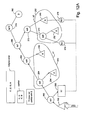
- FIG. 8A shows a general execution plan in accordance with the present invention.
- the execution plan has four groups p 1 104 , p 2 106 , p 3 108 and p 4 110 , nine operators op 1 112 , op 2 114 , op 3 , 116 , op 4 118 , op 5 120 , op 7 122 , op 8 124 , op 9 126 , op 10 128 , an activating statement tree S 130 , a temporary table TT 132 , scan operators sc 1 134 sc 2 105 , sc 3 107 and sc 4 109 , and a deletion operator D 136 .
- there are pair-wise conflicts (for purposes of illustration) between t 1 and t 2 , and t 2 and t 3 , and that the order of creation of the triggers is indicated by the trigger subscript.
- group p 1 has two triggers t 1 and t 4 that are joined by op 2 , a parallel union operator that enables parallel execution of triggers t 1 and t 4 .
- group p 1 is a group of row triggers, the group can execute in a pipelined fashion with the activating statement S and op 3 is a flow operator.
- op 3 is an ordered union operator. As described above, an ordered union operator prevents execution of the right leg of a tree until execution of the left leg has completed.
- Group p 2 in FIG. 8A has two triggers t 2 and t 5 and these triggers are joined by parallel union operator op 4 to permit their concurrent execution.
- Group p 2 is joined to the tree by op 5 , which is an ordered union operator because of the assumed conflict between t 1 and t 2 .
- Ordered union operator op 5 guarantees that group p 1 completes execution before the execution of group p 2 starts.
- Group p 3 in FIG. 8A contains two triggers t 3 and t 6 which are joined by op 8 , a parallel union operator to permit triggers t 3 and t 6 to execute in parallel.
- This group is joined, via op 9 , an ordered union operator, to group p 4 , which contains trigger t 7 .
- This arrangement in effect, causes triggers in groups p 3 and p 4 to execute as if they were a single group.
- Trigger t 7 is connected to execute in parallel with the parallel execution of triggers t 3 and t 6 .
- Operator op 9 is connected to the rest of the tree via op 7 , an ordered union operator, because of the assumed conflict between t 3 and t 2 .
- triggers t 3 and t 6 can be different in type from trigger t 7 .
- triggers t 3 and t 6 can be row triggers and t 7 can be a statement trigger.
- the connections of op 8 and op 9 thus provide a way of forming hybrid groups, i.e., groups of triggers that are not all of the same type.
- Triggers in groups p 1 , p 2 , p 3 and p 4 may need the assistance of a temporary table TT and scan operators, such as sc 1 -sc 4 , to have access to rows affected by the activating statement.
- the execution plan includes scan operators connected to triggers, as needed, to scan the temporary table TT for input.
- the temporary table is connected via a flow operator op 1 to the operator tree of the activating statement so that it accumulates the affected rows in pipelined fashion with the execution of the activating statement. If the group p 1 contains row triggers, this group obtains input from the execution of the activating statement without the need of a scan operator.
- groups p 2 and p 4 contain statement triggers (i.e., t 2 , t 5 and t 7 are statement triggers), these statement triggers may need to scan the temporary table TT 132 to have access to the rows affected by the activating statement.
- a deletion operator D 136 is connected to the rest of the tree via op 10 , an ordered union operator.
- the deletion operate clears the accumulated rows in the temporary table when the execution of the rest of the plan is completed
- FIG. 8A clearly creates efficient execution of the triggers involved. Triggers that can execute in parallel do so and those having conflicts with other triggers execute in the order of their creation time stamp.
- FIG. 8B illustrates the concurrency in execution caused by the given tree of FIG. 8 A.
- FIGS. 9A and 9B show a flow charts for creating an execution plan when there is a possibility of two or more conflicting triggers.
- any trigger actions that are activated by the activating statement S are identified.
- An operator tree, in step 142 , for the activating statement is constructed, and in step 144 , the an action tree for each activated trigger is constructed.
- the order of steps 142 and 144 is not critical.
- Each activated trigger, an after-trigger has a creation time stamp that indicates when it was created. The creation time stamp is needed in case some of the triggers are determined to be conflicting triggers because these triggers must be executed sequentially in the order in which they were created.
- the tables in the database that are read or written (accessed) by the activated triggers are determined, so that, in step 148 , any data access conflicts between the activated triggers can be determined.
- step 150 If there are no data access conflicts, as determined in step 150 , then the activated triggers are combined into a single group, in step 152 .
- a temporary table is interconnected to the operator tree of the activating statement S in step 154 , and the combined group is then connected to the resulting tree in step 155 . If there are any row triggers in the group, they can be split off from the group and joined with a flow operator so that they can be pipelined with the execution of the operator tree for S, such as is shown in FIG. 6 A.
- a transformation step 156 is performed on the activated triggers to create two or more parallel groups of activated triggers, such as those described in reference to FIG. 8 A.
- Parallel groups of triggers such as p 1 , p 2 and combined group p 3 /p 4 in FIG. 8A, are groups that have no conflicts among triggers within the group so that the triggers in the group execute in parallel with each other but have conflicts between two or more triggers within the groups.
- step 158 the parallel groups of triggers are joined to each other so that groups are configured execute serially relative to each other, in the order of the creation time stamp of the conflicting trigger within the parallel group.
- p 2 executes after p 1
- p 3 after p 2 .
- the serial execution of groups is enforced via ordered union operators, op 3 , op 5 and op 7 of FIG. 8 A.
- the flow of FIG. 9 A and the resulting plan in FIG. 8A substantially reduce execution time while preserving the order of triggers that conflict with each other to be the order in which those triggers were created.
- FIG. 9B shows the transformation step 156 in more detail.
- the activated triggers are ordered by their creation time stamps and, in step 162 , the activated triggers are re-ordered to juxtapose, where possible, triggers between which there are no data access conflicts.
- the creation time stamp of triggers t 1 -t 7 is the order of the subscripts. After reordering, the triggers have the following order: t 1 , t 4 , t 2 , t 5 , t 3 , t 6 , t 7 . This re-ordering facilitates the identification of a possible row trigger group that can be connected for pipelined execution with the operator tree.
- FIG. 8A the creation time stamp of triggers t 1 -t 7 is the order of the subscripts.
- triggers t 1 and t 4 are row triggers, then can be connected for pipelined execution with the operator tree, if op 3 is a flow operator and op 2 is a parallel union operator (flow operator op 1 for the temporary table does not interfere with flow operator op 3 ).
- the re-ordered triggers are then separated into a plurality of groups, p 1 , p 2 , and p 3 as shown in FIG. 8A, given the assumed conflicts.
- FIG. 10A shows a specific execution plan, created in accordance with the process of FIGS. 9A and 9B, in which a temporary table and scan operator are employed when there are conflicting statement triggers.
- there are four triggers t 1 170 , t 2 172 , t 3 174 , and t 4 176 , three groups, p 1 178 , p 2 180 and p 3 182 , a temporary table TT 184 , two scan operators sc 1 186 and sc 2 188 , six operators op 1 190 , op 3 192 , op 4 194 , op 5 196 , op 7 198 , op 8 200 and a deletion operator 202 .
- Triggers t 1 -t 4 are assumed to have creation time stamps in the order of their subscripts.
- Temporary table TT is present to accumulate rows processed by the operator tree of the activating statement S so that statement (or row) triggers can have access to the processed rows.
- Scan operators sc 1 and sc 2 are used to read the temporary table and provide input the statement trigger.
- a deletion operator 202 for clearing the temporary table is interconnected to op 7 via an ordered union operator op 8 , so that when of all of the operations in the execution plan are completed the deletion operator clears the temporary table.
- This deletion operator D is connected to an execution plan any time a temporary table is employed.
- group p 1 is assumed to contain two row triggers t 1 and t 4 that can execute in parallel, so this group is connected to the operator tree of the activating statement by a flow operator.
- Groups p 2 and p 3 are assumed to each contain statement triggers t 2 and t 3 between which there is a conflict. Because of the conflict, parallel groups p 2 and p 3 must execute sequentially so they are connected to each other by an ordered union operator op 7 .
- Group p 2 must be interconnected via an ordered union operator op 5 for execution subsequent to the execution of group p 1 and the operator tree for statement S, because statement-after trigger t 2 conflicts with the execution activating statement S.
- FIG. 10 B The time to execute the execution plan of FIG. 10A is summarized in FIG. 10 B.
- row triggers t 1 and t 4 having been brought forward, are interconnected to execute in parallel with each other and in a pipelined fashion with the execution of the operator tree for the activating statement S.
- Triggers t 2 and t 3 execute serially in the order of their creation time stamp because of the conflict.
- Statement trigger t 2 executes after the execution of the operator tree for statement S, because of the inherent conflict of a statement trigger with its activating statement.
- FIG. 11A shows another specific execution plan, created in accordance with the process of FIGS. 9A and 9B, for the case where there is a conflict between a row trigger and a statement trigger.
- there are four triggers t 4 210 , t 5 212 , t 6 214 , and t 8 216 , having a creation time stamp order according to their subscripts, three groups, p 1 218 , p 2 220 and p 3 222 , a temporary table TT 224 , three scan operators sc 1 226 , sc 2 228 , sc 3 230 , a deletion operator 232 , and seven operators op 1 234 , op 3 236 , op 5 238 , op 6 240 , op 7 242 , op 8 244 , and op 9 246 .
- a deletion operator 232 is connected via op 9 , an ordered union operator, to clear the TT table when the
- op 1 can be a flow operator to connect p 1 to the operator tree of the activating statement for pipelined execution in accordance with the heuristic of bringing row triggers forward.
- Group p 2 is assumed to contain statement triggers t 5 and t 6 , between which there are no conflicts. Therefore, triggers t 5 and t 6 are joined together by op 6 , which is a parallel union operator and this group is connected to the op 3 operator by means of an ordered union operator op 5 , when op 3 is a flow operator to assure that group p 2 executes after activating statement S.
- op 6 which is a parallel union operator and this group is connected to the op 3 operator by means of an ordered union operator op 5 , when op 3 is a flow operator to assure that group p 2 executes after activating statement S.
- Group p 3 is assumed to contain a row trigger t 8 that conflicts with statement trigger t 6 in group p 2 so conflicting group p 3 must interconnected to group p 2 by means of an ordered union operator, op 7 , in this case.
- the temporary table TT is connected to the operator tree for the activating statement S by op 1 , which is a flow operator, so that the temporary table can accumulate rows as they are produced by the execution of the operator tree.
- Scan operators, sc 1 , sc 2 and sc 3 provide input to statement triggers t 5 and t 6 and row trigger t 8 .
- Operator op 8 is a flow operator that serves to interconnect the row trigger t 8 to the scan operator sc 3 for pipelined execution with the scan operator sc 3 .
- FIG. 11 B The time line for the execution of the plan in FIG. 11A is illustrated in FIG. 11 B.
- row trigger t 4 executes in a pipelined fashion with S
- statement triggers t 5 and t 6 execute in parallel with each other and subsequent to the execution of the activating statement because of the inherent conflict between statement triggers and the activating statement
- row trigger t 8 executes after the execution of t 5 and t 6 is completed, because of the conflict between t 8 and t 6 .
- triggers t 6 and t 8 execute serially in the order of their creation time stamps.
- FIG. 12A shows another specific execution plan, created in accordance with the process of FIGS. 9A and 9B, that combines a row trigger and statement trigger into effectively the same group.
- the deletion operator is connected via op 10 , an ordered union operator, to clear the temporary table TT when the execution of the plan is completed.
- Group p 1 includes triggers t 1 , assumed to be a row trigger, and t 3 , assumed to be a statement trigger, between which there are no conflicts. Furthermore, statement trigger t 3 does not conflict with the operator tree for the activating statement S.
- the triggers of group p 1 are joined by a parallel union operator op 5 .
- Group p 1 also includes a flow operator op 3 so that row trigger t 1 can execute in a pipelined fashion with its input. Because op 1 is a flow operator, this allows trigger t 1 to execute in a pipelined fashion with the operator tree for the activating statement S. Thus, t 1 executes in a pipelined fashion with the activating statement, and t 3 executes in parallel with t 1 .
- Group p 2 includes triggers t 2 , which is assumed to be a row trigger and t 4 which is assumed to be a statement trigger.
- the triggers t 2 and t 4 are joined by parallel union operator op 9 .
- Group p 2 also includes a flow operator so that the row trigger can operate in a pipelined fashion with scan operator sc 1 , which scans temporary table TT for input to the row trigger t 2 .
- a second scan operator sc 2 provides input for trigger t 4 from the temporary table TT.
- group p 1 must complete execution before the beginning of execution of group p 2 .
- This ordering is guaranteed by an ordered union operator op 7 which interconnects the parallel union operator op 5 for group p 1 and the parallel union operator op 9 for group p 2 .
- FIG. 12B shows a timing chart for the execution of the timing plan of FIG. 12 A.
- Trigger t 1 executes in a pipelined fashion with activating statement S and trigger t 3 executes in parallel with trigger t 1 .
- trigger t 2 starts.
- Trigger t 4 is depicted as executing in parallel to trigger t 2 (because of the parallel union operator op 9 ).
- the total execution time for the execution plan of FIG. 12A is substantially reduced from the serial execution of all of the triggers. However, the original order of conflicting triggers is still preserved.
Abstract
Description
Claims (17)
Priority Applications (1)
| Application Number | Priority Date | Filing Date | Title |
|---|---|---|---|
| US09/823,340 US6711560B2 (en) | 2001-03-29 | 2001-03-29 | Method of executing conflicting triggers in an active database |
Applications Claiming Priority (1)
| Application Number | Priority Date | Filing Date | Title |
|---|---|---|---|
| US09/823,340 US6711560B2 (en) | 2001-03-29 | 2001-03-29 | Method of executing conflicting triggers in an active database |
Publications (2)
| Publication Number | Publication Date |
|---|---|
| US20020143746A1 US20020143746A1 (en) | 2002-10-03 |
| US6711560B2 true US6711560B2 (en) | 2004-03-23 |
Family
ID=25238485
Family Applications (1)
| Application Number | Title | Priority Date | Filing Date |
|---|---|---|---|
| US09/823,340 Expired - Lifetime US6711560B2 (en) | 2001-03-29 | 2001-03-29 | Method of executing conflicting triggers in an active database |
Country Status (1)
| Country | Link |
|---|---|
| US (1) | US6711560B2 (en) |
Cited By (19)
| Publication number | Priority date | Publication date | Assignee | Title |
|---|---|---|---|---|
| US20020198726A1 (en) * | 2001-06-21 | 2002-12-26 | International Business Machines Corporation | Self join elimination through union |
| US20050044089A1 (en) * | 2003-08-21 | 2005-02-24 | Microsoft Corporation | Systems and methods for interfacing application programs with an item-based storage platform |
| US20050125409A1 (en) * | 2003-12-04 | 2005-06-09 | International Business Machines Corporation | Query access plan rebuilds |
| US20050222978A1 (en) * | 2004-03-31 | 2005-10-06 | Tal Drory | Method and apparatus for querying spatial data |
| US20050235001A1 (en) * | 2004-03-31 | 2005-10-20 | Nitzan Peleg | Method and apparatus for refreshing materialized views |
| US20060195456A1 (en) * | 2005-02-28 | 2006-08-31 | Microsoft Corporation | Change notification query multiplexing |
| US7174553B1 (en) * | 2002-11-22 | 2007-02-06 | Ncr Corp. | Increasing parallelism of function evaluation in a database |
| US20070088724A1 (en) * | 2003-08-21 | 2007-04-19 | Microsoft Corporation | Systems and methods for extensions and inheritance for units of information manageable by a hardware/software interface system |
| US20090157737A1 (en) * | 2007-12-13 | 2009-06-18 | Rafal Przemyslaw Konik | Database Trigger Modification System and Method |
| US7991779B1 (en) | 2005-04-25 | 2011-08-02 | Hewlett Packard Development Company, L.P. | Method and apparatus for populating an index table |
| USRE42664E1 (en) * | 1993-09-27 | 2011-08-30 | Oracle International Corporation | Method and apparatus for implementing parallel operations in a database management system |
| US8166101B2 (en) | 2003-08-21 | 2012-04-24 | Microsoft Corporation | Systems and methods for the implementation of a synchronization schemas for units of information manageable by a hardware/software interface system |
| US20120137297A1 (en) * | 2010-11-30 | 2012-05-31 | Sap Ag | Modifying scheduled execution of object modification methods associated with database objects |
| US8238696B2 (en) | 2003-08-21 | 2012-08-07 | Microsoft Corporation | Systems and methods for the implementation of a digital images schema for organizing units of information manageable by a hardware/software interface system |
| US8527471B2 (en) | 2010-12-27 | 2013-09-03 | Sap Ag | Shadow system mirroring of an original system during uptime of an upgrade process |
| US8706769B1 (en) * | 2009-12-31 | 2014-04-22 | Teradata Us, Inc. | Processing insert with normalize statements |
| US9092474B2 (en) | 2010-10-12 | 2015-07-28 | Sap Se | Incremental conversion of database objects during upgrade of an original system |
| US9213728B2 (en) | 2011-12-14 | 2015-12-15 | Sap Se | Change data capturing during an upgrade |
| US9626390B2 (en) | 2010-12-27 | 2017-04-18 | Sap Se | Shadow system start during upgrade of an original system |
Families Citing this family (5)
| Publication number | Priority date | Publication date | Assignee | Title |
|---|---|---|---|---|
| US8589435B2 (en) * | 2004-06-08 | 2013-11-19 | International Business Machines Corporation | Method, system and program for simplifying data flow in a statement with sequenced subexpressions |
| US20070094233A1 (en) * | 2005-10-24 | 2007-04-26 | Wolfgang Otter | Translating time-independent data using database operations |
| US8799318B2 (en) * | 2012-07-27 | 2014-08-05 | Sap Ag | Function module leveraging fuzzy search capability |
| US9612921B2 (en) * | 2013-03-01 | 2017-04-04 | Teradata Us, Inc. | Method and system for load balancing a distributed database providing object-level management and recovery |
| US10216774B2 (en) * | 2016-06-24 | 2019-02-26 | International Business Machines Corporation | Multiple versions of triggers in a database system |
Citations (12)
| Publication number | Priority date | Publication date | Assignee | Title |
|---|---|---|---|---|
| US5680602A (en) * | 1995-04-11 | 1997-10-21 | International Business Machines Corporation | Trigger generation in an active database management system |
| US5864842A (en) | 1995-10-23 | 1999-01-26 | Ncr Corporation | Optimization of SQL queries using hash star join operations |
| US5873075A (en) * | 1997-06-30 | 1999-02-16 | International Business Machines Corporation | Synchronization of SQL actions in a relational database system |
| US5875334A (en) | 1995-10-27 | 1999-02-23 | International Business Machines Corporation | System, method, and program for extending a SQL compiler for handling control statements packaged with SQL query statements |
| US5881232A (en) | 1996-07-23 | 1999-03-09 | International Business Machines Corporation | Generic SQL query agent |
| US5884299A (en) | 1997-02-06 | 1999-03-16 | Ncr Corporation | Optimization of SQL queries involving aggregate expressions using a plurality of local and global aggregation operations |
| US5890148A (en) | 1994-12-30 | 1999-03-30 | International Business Machines Corporation | System and method for generating uniqueness information for optimizing an SQL query |
| US5930795A (en) | 1997-01-21 | 1999-07-27 | International Business Machines Corporation | Supporting dynamic tables in SQL query compilers |
| US5950188A (en) | 1996-11-14 | 1999-09-07 | Sybase, Inc. | Database system with methods for executing system-created internal SQL command statements |
| US6385603B1 (en) * | 1999-06-14 | 2002-05-07 | International Business Machines Corporation | Joined table expression optimization by query transformation |
| US6405212B1 (en) * | 1999-09-27 | 2002-06-11 | Oracle Corporation | Database system event triggers |
| US6594656B1 (en) * | 1999-01-22 | 2003-07-15 | Avaya Technology Corp. | Active database trigger processing using a trigger gateway |
-
2001
- 2001-03-29 US US09/823,340 patent/US6711560B2/en not_active Expired - Lifetime
Patent Citations (12)
| Publication number | Priority date | Publication date | Assignee | Title |
|---|---|---|---|---|
| US5890148A (en) | 1994-12-30 | 1999-03-30 | International Business Machines Corporation | System and method for generating uniqueness information for optimizing an SQL query |
| US5680602A (en) * | 1995-04-11 | 1997-10-21 | International Business Machines Corporation | Trigger generation in an active database management system |
| US5864842A (en) | 1995-10-23 | 1999-01-26 | Ncr Corporation | Optimization of SQL queries using hash star join operations |
| US5875334A (en) | 1995-10-27 | 1999-02-23 | International Business Machines Corporation | System, method, and program for extending a SQL compiler for handling control statements packaged with SQL query statements |
| US5881232A (en) | 1996-07-23 | 1999-03-09 | International Business Machines Corporation | Generic SQL query agent |
| US5950188A (en) | 1996-11-14 | 1999-09-07 | Sybase, Inc. | Database system with methods for executing system-created internal SQL command statements |
| US5930795A (en) | 1997-01-21 | 1999-07-27 | International Business Machines Corporation | Supporting dynamic tables in SQL query compilers |
| US5884299A (en) | 1997-02-06 | 1999-03-16 | Ncr Corporation | Optimization of SQL queries involving aggregate expressions using a plurality of local and global aggregation operations |
| US5873075A (en) * | 1997-06-30 | 1999-02-16 | International Business Machines Corporation | Synchronization of SQL actions in a relational database system |
| US6594656B1 (en) * | 1999-01-22 | 2003-07-15 | Avaya Technology Corp. | Active database trigger processing using a trigger gateway |
| US6385603B1 (en) * | 1999-06-14 | 2002-05-07 | International Business Machines Corporation | Joined table expression optimization by query transformation |
| US6405212B1 (en) * | 1999-09-27 | 2002-06-11 | Oracle Corporation | Database system event triggers |
Cited By (30)
| Publication number | Priority date | Publication date | Assignee | Title |
|---|---|---|---|---|
| USRE42664E1 (en) * | 1993-09-27 | 2011-08-30 | Oracle International Corporation | Method and apparatus for implementing parallel operations in a database management system |
| US7107255B2 (en) * | 2001-06-21 | 2006-09-12 | International Business Machines Corporation | Self join elimination through union |
| US20020198726A1 (en) * | 2001-06-21 | 2002-12-26 | International Business Machines Corporation | Self join elimination through union |
| US7440937B2 (en) | 2001-06-21 | 2008-10-21 | International Business Machines Corporation | Self join elimination through union |
| US20060265356A1 (en) * | 2001-06-21 | 2006-11-23 | Kiernan Gerald G | Self join elimination through union |
| US7174553B1 (en) * | 2002-11-22 | 2007-02-06 | Ncr Corp. | Increasing parallelism of function evaluation in a database |
| US8238696B2 (en) | 2003-08-21 | 2012-08-07 | Microsoft Corporation | Systems and methods for the implementation of a digital images schema for organizing units of information manageable by a hardware/software interface system |
| US8166101B2 (en) | 2003-08-21 | 2012-04-24 | Microsoft Corporation | Systems and methods for the implementation of a synchronization schemas for units of information manageable by a hardware/software interface system |
| US20070088724A1 (en) * | 2003-08-21 | 2007-04-19 | Microsoft Corporation | Systems and methods for extensions and inheritance for units of information manageable by a hardware/software interface system |
| US20050044089A1 (en) * | 2003-08-21 | 2005-02-24 | Microsoft Corporation | Systems and methods for interfacing application programs with an item-based storage platform |
| US7917534B2 (en) | 2003-08-21 | 2011-03-29 | Microsoft Corporation | Systems and methods for extensions and inheritance for units of information manageable by a hardware/software interface system |
| US8131739B2 (en) | 2003-08-21 | 2012-03-06 | Microsoft Corporation | Systems and methods for interfacing application programs with an item-based storage platform |
| US20050125409A1 (en) * | 2003-12-04 | 2005-06-09 | International Business Machines Corporation | Query access plan rebuilds |
| US7133861B2 (en) * | 2003-12-04 | 2006-11-07 | International Business Machines Corporation | Query access plan rebuilds |
| US20050235001A1 (en) * | 2004-03-31 | 2005-10-20 | Nitzan Peleg | Method and apparatus for refreshing materialized views |
| US20050222978A1 (en) * | 2004-03-31 | 2005-10-06 | Tal Drory | Method and apparatus for querying spatial data |
| US7945569B2 (en) | 2004-03-31 | 2011-05-17 | Hewlett-Packard Development Company, L.P. | Method and apparatus for querying spatial data |
| US7805422B2 (en) * | 2005-02-28 | 2010-09-28 | Microsoft Corporation | Change notification query multiplexing |
| US20060195456A1 (en) * | 2005-02-28 | 2006-08-31 | Microsoft Corporation | Change notification query multiplexing |
| US7991779B1 (en) | 2005-04-25 | 2011-08-02 | Hewlett Packard Development Company, L.P. | Method and apparatus for populating an index table |
| US20090157737A1 (en) * | 2007-12-13 | 2009-06-18 | Rafal Przemyslaw Konik | Database Trigger Modification System and Method |
| US8396846B2 (en) * | 2007-12-13 | 2013-03-12 | International Business Machines Corporation | Database trigger modification system and method |
| US8706769B1 (en) * | 2009-12-31 | 2014-04-22 | Teradata Us, Inc. | Processing insert with normalize statements |
| US9092474B2 (en) | 2010-10-12 | 2015-07-28 | Sap Se | Incremental conversion of database objects during upgrade of an original system |
| US20120137297A1 (en) * | 2010-11-30 | 2012-05-31 | Sap Ag | Modifying scheduled execution of object modification methods associated with database objects |
| US8984514B2 (en) * | 2010-11-30 | 2015-03-17 | Sap Se | Modifying scheduled execution of object modification methods associated with database objects |
| US8527471B2 (en) | 2010-12-27 | 2013-09-03 | Sap Ag | Shadow system mirroring of an original system during uptime of an upgrade process |
| US8924350B2 (en) | 2010-12-27 | 2014-12-30 | Sap Se | Shadow system mirroring of an original system during uptime of an upgrade process |
| US9626390B2 (en) | 2010-12-27 | 2017-04-18 | Sap Se | Shadow system start during upgrade of an original system |
| US9213728B2 (en) | 2011-12-14 | 2015-12-15 | Sap Se | Change data capturing during an upgrade |
Also Published As
| Publication number | Publication date |
|---|---|
| US20020143746A1 (en) | 2002-10-03 |
Similar Documents
| Publication | Publication Date | Title |
|---|---|---|
| US6711560B2 (en) | Method of executing conflicting triggers in an active database | |
| US6745174B2 (en) | Method of executing before-triggers in an active database | |
| US5963933A (en) | Efficient implementation of full outer join and anti-join | |
| US7111025B2 (en) | Information retrieval system and method using index ANDing for improving performance | |
| JP3297403B2 (en) | Method and apparatus for query optimization | |
| US5752017A (en) | Method and apparatus for executing complex SQL queries using projection operations | |
| US7275056B2 (en) | System and method for transforming queries using window aggregation | |
| US5615361A (en) | Exploitation of uniqueness properties using a 1-tuple condition for the optimization of SQL queries | |
| US7185024B2 (en) | Method, computer program product, and system of optimized data translation from relational data storage to hierarchical structure | |
| US8200657B2 (en) | Processing cross-table non-boolean term conditions in database queries | |
| US5276870A (en) | View composition in a data base management system | |
| US6085189A (en) | Database system and method for supporting current of cursor updates and deletes from a select query from one or more updatable tables in single node and MPP environments | |
| US6721725B2 (en) | Method of parallel trigger execution in an active database | |
| US6834279B1 (en) | Method and system for inclusion hash joins and exclusion hash joins in relational databases | |
| CN100399324C (en) | Processing method for embedded data bank searching | |
| US7080072B1 (en) | Row hash match scan in a partitioned database system | |
| Dayal | Processing queries with quantifiers a horticultural approach | |
| US8214408B2 (en) | Method, database system and computer program for joining temporal database tables | |
| US7213011B1 (en) | Efficient processing of multi-column and function-based in-list predicates | |
| US6618720B1 (en) | Common spool files for maintaining join indexes | |
| US6999967B1 (en) | Semantically reducing the number of partitions involved in a join | |
| Zhu et al. | Developing a dynamic materialized view index for efficiently discovering usable views for progressive queries | |
| Morton et al. | Pro Oracle SQL | |
| Sheth et al. | Q-data: Using deductive database technology to improve data quality | |
| US20020138464A1 (en) | Method and apparatus to index a historical database for efficient multiattribute SQL queries |
Legal Events
| Date | Code | Title | Description |
|---|---|---|---|
| AS | Assignment |
Owner name: COMPAQ COMPUTER CORPORATION, TEXAS Free format text: ASSIGNMENT OF ASSIGNORS INTEREST;ASSIGNORS:LEVY, ELIEZER;SHERMAN, YUVAL;PELEG, NITZAN;REEL/FRAME:011664/0637 Effective date: 20010327 |
|
| AS | Assignment |
Owner name: COMPAQ INFORMATION TECHNOLOGIES GROUP, L.P., TEXAS Free format text: ASSIGNMENT OF ASSIGNORS INTEREST;ASSIGNOR:COMPAQ COMPUTER CORPORATION;REEL/FRAME:012403/0437 Effective date: 20010620 |
|
| AS | Assignment |
Owner name: HEWLETT-PACKARD DEVELOPMENT COMPANY, L.P., TEXAS Free format text: CHANGE OF NAME;ASSIGNOR:COMPAQ INFORMATION TECHNOLOGIES GROUP L.P.;REEL/FRAME:014177/0428 Effective date: 20021001 Owner name: HEWLETT-PACKARD DEVELOPMENT COMPANY, L.P.,TEXAS Free format text: CHANGE OF NAME;ASSIGNOR:COMPAQ INFORMATION TECHNOLOGIES GROUP L.P.;REEL/FRAME:014177/0428 Effective date: 20021001 |
|
| STCF | Information on status: patent grant |
Free format text: PATENTED CASE |
|
| FEPP | Fee payment procedure |
Free format text: PAYOR NUMBER ASSIGNED (ORIGINAL EVENT CODE: ASPN); ENTITY STATUS OF PATENT OWNER: LARGE ENTITY Free format text: PAYER NUMBER DE-ASSIGNED (ORIGINAL EVENT CODE: RMPN); ENTITY STATUS OF PATENT OWNER: LARGE ENTITY |
|
| FPAY | Fee payment |
Year of fee payment: 4 |
|
| REMI | Maintenance fee reminder mailed | ||
| FPAY | Fee payment |
Year of fee payment: 8 |
|
| AS | Assignment |
Owner name: GOOGLE INC., CALIFORNIA Free format text: ASSIGNMENT OF ASSIGNORS INTEREST;ASSIGNORS:HEWLETT-PACKARD DEVELOPMENT COMPANY, L.P.;HEWLETT-PACKARD COMPANY;REEL/FRAME:027661/0258 Effective date: 20111025 |
|
| FPAY | Fee payment |
Year of fee payment: 12 |
|
| AS | Assignment |
Owner name: GOOGLE LLC, CALIFORNIA Free format text: CHANGE OF NAME;ASSIGNOR:GOOGLE INC.;REEL/FRAME:044127/0735 Effective date: 20170929 |