US6717921B1 - Method for configuring a shared tree for routing traffic in a multicast conference - Google Patents
Method for configuring a shared tree for routing traffic in a multicast conference Download PDFInfo
- Publication number
- US6717921B1 US6717921B1 US09/573,783 US57378300A US6717921B1 US 6717921 B1 US6717921 B1 US 6717921B1 US 57378300 A US57378300 A US 57378300A US 6717921 B1 US6717921 B1 US 6717921B1
- Authority
- US
- United States
- Prior art keywords
- tree
- node
- nodes
- terminating
- delay
- Prior art date
- Legal status (The legal status is an assumption and is not a legal conclusion. Google has not performed a legal analysis and makes no representation as to the accuracy of the status listed.)
- Expired - Lifetime
Links
Images


Classifications
-
- H—ELECTRICITY
- H04—ELECTRIC COMMUNICATION TECHNIQUE
- H04L—TRANSMISSION OF DIGITAL INFORMATION, e.g. TELEGRAPHIC COMMUNICATION
- H04L45/00—Routing or path finding of packets in data switching networks
- H04L45/48—Routing tree calculation
-
- H—ELECTRICITY
- H04—ELECTRIC COMMUNICATION TECHNIQUE
- H04L—TRANSMISSION OF DIGITAL INFORMATION, e.g. TELEGRAPHIC COMMUNICATION
- H04L12/00—Data switching networks
- H04L12/02—Details
- H04L12/16—Arrangements for providing special services to substations
- H04L12/18—Arrangements for providing special services to substations for broadcast or conference, e.g. multicast
- H04L12/1813—Arrangements for providing special services to substations for broadcast or conference, e.g. multicast for computer conferences, e.g. chat rooms
- H04L12/1827—Network arrangements for conference optimisation or adaptation
-
- H—ELECTRICITY
- H04—ELECTRIC COMMUNICATION TECHNIQUE
- H04L—TRANSMISSION OF DIGITAL INFORMATION, e.g. TELEGRAPHIC COMMUNICATION
- H04L12/00—Data switching networks
- H04L12/02—Details
- H04L12/16—Arrangements for providing special services to substations
- H04L12/18—Arrangements for providing special services to substations for broadcast or conference, e.g. multicast
- H04L12/185—Arrangements for providing special services to substations for broadcast or conference, e.g. multicast with management of multicast group membership
-
- H—ELECTRICITY
- H04—ELECTRIC COMMUNICATION TECHNIQUE
- H04L—TRANSMISSION OF DIGITAL INFORMATION, e.g. TELEGRAPHIC COMMUNICATION
- H04L45/00—Routing or path finding of packets in data switching networks
-
- H—ELECTRICITY
- H04—ELECTRIC COMMUNICATION TECHNIQUE
- H04L—TRANSMISSION OF DIGITAL INFORMATION, e.g. TELEGRAPHIC COMMUNICATION
- H04L45/00—Routing or path finding of packets in data switching networks
- H04L45/12—Shortest path evaluation
- H04L45/124—Shortest path evaluation using a combination of metrics
-
- H—ELECTRICITY
- H04—ELECTRIC COMMUNICATION TECHNIQUE
- H04L—TRANSMISSION OF DIGITAL INFORMATION, e.g. TELEGRAPHIC COMMUNICATION
- H04L45/00—Routing or path finding of packets in data switching networks
- H04L45/16—Multipoint routing
Definitions
- This invention relates to methods for routing multicast data communications. More specifically, it relates to a method for configuring a close-to-optimal Steiner tree for routing data communications traffic associated with a multicast conference call subject to a predetermined end-to-end delay requirement.
- Multicasting presents a communications paradigm in which communications initiated by a sending party are broadcast to a plurality of receiving parties.
- Internet Protocol (IP) multicasting applications represent a significant segment for multicasting applications.
- IP applications for multicasting include audio and video conferencing, streaming audio and video applications, and document and software distribution (see, e.g., Sanjoy Paul, Multicasting On The Internet And Its Applications, Kluwer Academic Publishers, Boston, 1998, pp.9-10).
- Real time applications such as audio and video conferencing present stringent delay requirements for multicast packets transmitted over IP networks.
- Typical sender-to-receiver latency for example, may be required to be less than 100 milliseconds.
- Multicast network facilities costs consumed represent an additional concern for IP multicast network operators.
- trees are often employed to facilitate multicast routing (see, e.g., V. P. Kompella et al., “Multicast Routing for Multimedia Communication,” IEEE/ACM Transactions On Networking, Vol. 1, No. 3, June 1993, pp. 286-292).
- Such trees are defined by a plurality of routers (“nodes”) for transmitting multicast conference packets over a plurality of data transmission links (“arcs”) that interconnect node pairs.
- Multicast conference participants (“senders” and “receivers”) are terminated on at least a subset of the plurality of routers (“terminating nodes”).
- Multicast trees provide for efficient conference routing, as each packet that must be forwarded by a sender to a number of receivers need only be copied at each node that branches to at least two nodes or that serves at least two receivers. As a result, the sender's node is most often required to produce a number of copies that is fewer in number than the number of receivers. This may be contrasted, for example, with unicast methods that require the sender to produce individual packet copies for each intended receiver.
- SPT shortest path tree
- MCT minimum cost tree
- CT constrained tree
- SPT methods are used to produce a multicast tree such that the cost of facilities between a selected sender and each identified receiver is minimized.
- MCT methods focus on minimizing total facilities costs for the multicast tree.
- CT methods focus on minimizing overall facilities costs subject to additional constraints.
- a representative CT method used for multicast routing is the constrained Steiner tree method (see Kompella, op cit. at pp. 286-289).
- a minimum Steiner tree may be defined as a network tree which is constructed such that the sum of a series of “penalties” (for example, such as network facilities costs) that can be associated with each arc in the tree are minimized.
- a constrained Steiner tree may be heuristically constructed as “close-to-optimal,” such that the tree approaches a theoretical minimum penalty subject to one or more constraints. For example, a typical constraint may require that the expected delay on each path between a sender and a receiver does not exceed a predetermined maximum.
- Kompella discloses a constrained Steiner tree method directed to produce a multicast tree supporting one sender and a plurality of receivers.
- emerging conferencing applications in multicasting are requiring that each participant to be capable of acting either as a sender or a receiver. Therefore, it would be advantageous to develop a constrained Steiner tree method that produces a close-to-optimal Steiner tree for a multicast conference in which any participant may function as either a sender or a receiver.
- the art is advanced by a novel and non-obvious method directed to configuring a close-to-optimal Steiner tree with low facilities cost constrained by a desired maximum end-to-end delay T between each pair of participants.
- the method begins by initializing the tree with a node that terminates at least one of the participants. While one or more nodes that terminate participants have not been added to the tree, additional nodes are incrementally selected from among nodes not yet selected or added to the tree such that each selected node adds a least additional penalty over its identified path to the current tree. When the selected node is a terminating node, the node is added to the tree along with any other selected nodes and arcs in its path to the tree.
- the method further incorporates a penalty function that addresses the maximum delay constraint by using a Lagrangian-like relaxation technique to combine both cost and delay into a single incremental penalty function.
- a penalty function that addresses the maximum delay constraint by using a Lagrangian-like relaxation technique to combine both cost and delay into a single incremental penalty function.
- a novel path delay metric (“delta diameter”) is introduced that provides a measure of impact on the maximum expected end-to-end delay ⁇ that would result from the addition of each incrementally selected node to the tree.
- FIG. 1 shows a first multicast network with associated costs and delays
- FIG. 2 illustrates a minimum Steiner tree selected from the multicast network 100 of FIG. 1;
- FIGS. 3A and 3B depicts a method for configuring a close-to-optimal Steiner tree in a multicast network such as the network 100 of FIG. 1;
- FIG. 4 shows a second multicast network with associated facilities costs and delays, including a second Steiner tree selected to minimize end-to-end delay between any two nodes in the tree;
- FIG. 5A depicts a third Steiner tree with associated node diameters
- FIG. 5B depicts a table for tracking tree diameter and node diameters for Steiner tree 520 of FIG. 5A;
- FIG. 6A depicts the Steiner tree of FIG. 5A with node diameters updated to reflect the addition of a node 630 ;
- FIG. 6B depicts the table of FIG. 5B updated to reflect the addition of the node 630 ;
- FIG. 7A depicts the Steiner tree of FIG. 5A with the addition of selected nodes 731 , 733 , 735 and 737 ;
- FIGS. 7B through 7D show a table incrementally updated to track node diameters, tree diameters and delta diameters for selected nodes 731 , 733 and 735 , respectively;
- FIG. 7E shows a table tracking node diameters, tree diameter and delta diameter for selected node 737 ;
- FIG. 7F shows a table of FIG. 7E updated to reflect the addition of candidate node 737 as a tree node to Steiner tree 720 of FIG. 7A;
- FIG. 8 depicts the labeling of nodes selected for possible addition to a Steiner tree 820 based on a revised modified penalty function C Rev, i, j incorporating delta diameter;
- FIG. 9 depicts a search method for selecting toll factors for the revised modified cost function C Rev, i, j introduced in FIG. 8;
- FIG. 10 shows facilities costs and delays as a function of toll factor, for Steiner trees selected in a simulated network.
- FIG. 1 illustrates pertinent elements in a typical multicast network.
- Multicast network 100 comprises nodes 101 , 102 , 103 , 104 , 105 and 106 , as well as arcs 112 , 113 , 123 , 124 , 125 , 134 , 135 , 145 , 146 and 156 .
- arcs 112 , 113 , 123 , 124 , 125 , 134 , 135 , 145 , 146 and 156 are Associated with each of the arcs 112 , 113 , 123 , 124 , 125 , 134 , 135 , 145 , 146 and 156 .
- Each facilities cost 115 and path delay 117 relate to a portion of the multicast network defined by an associated arc and the two nodes interconnected by the arc.
- Facilities cost 115 provides a measure of the relative cost incurred in reserving the path defined by an associated arc and its interconnected node pair. For example, in FIG. 1, a cost 115 of 10 units is incurred by arc 113 and its interconnected nodes 101 and 103 .
- path delay 117 provides a measure of delay incurred for traffic along the defined path. For example, as shown in FIG. 1, the path defined by arc 135 and nodes 103 and 105 incurs a delay 117 of 3 units.
- the sum of the facilities costs associated with each of the arcs in the multicast network is indicative of the overall facilities costs for the network. For example, by summing each of the facilities costs 115 associated with the arcs 112 , 113 , 123 , 124 , 125 , 134 , 135 , 145 , 146 and 156 of the network 100 in FIG. 1, one determines an overall facilities cost for the network 100 of 45 units.
- Terminating nodes provide sole points of interconnection for multicast network participants (in other words, each participant is directly interconnected to at most one terminating node). As a result, for a multicast tree configured to support a multicast conference, the tree must include all terminating nodes associated with active multicast conference participants.
- a Steiner tree configures arcs, terminating nodes and other non-terminating nodes so that only a single network path is available between each pair of terminating nodes.
- nodes and arcs are selected so that the sum of certain penalties (for example, such as facilities costs) associated with each selected node and arc minimized (see, e.g., Sanjoy Paul, op cit. at pg. 25). Any penalty function may be employed that can be defined with reference to each incrementally selected node and arc and summed to indicate an overall penalty for the Steiner tree.
- FIG. 2 illustrates a minimum Steiner tree 220 configured in the network 200 .
- Steiner tree 220 is defined by terminating nodes 201 , 204 , and 205 , non-terminating node 202 and arcs 212 , 224 and 225 .
- An overall facilities cost 216 for the Steiner tree 220 is determined by summing cost labels associated with arcs 212 , 224 and 225 .
- Steiner tree 220 has a facilities cost 216 of 4 units. This cost is less, for example, than the facilities cost associated with an alternate multicast tree defined by terminating nodes 201 , 204 and 205 , non-terminating node 203 and arcs 213 , 234 and 235 . For this alternate multicast tree, the facilities cost is 25 units.
- FIG. 3A depicts one such heuristic method, related to a method proposed by Maxemchuck (see Nicholas F. Maxemchuck, “Video Distribution on Multicast Networks,” IEEE Journal on Selected Areas in Communications, Vol. 15, No. 3, April 1997, pp. 359-363).
- an initial terminating node is randomly selected at step 302 to begin the tree.
- the tree is initialized by labeling the selected tree node and all other nodes. Such node labeling may be practically accomplished, for example, in a data file containing records associated with the individual network nodes.
- the tree node is labeled as with a tree node label (T), a permanent node label (P), and a penalty value of 0 units (indicating that the selected node has been added to the tree).
- T tree node label
- P permanent node label
- penalty value of 0 units indicating that the selected node has been added to the tree.
- all other network nodes are labeled as having arbitrarily high penalty values (conceptually, penalties of infinite value), and have any pre-existing T or P labels removed.
- step 306 it is determined Whether any terminating nodes remain to be added to the tree. While at least one terminating node has not yet been added to the tree, the process proceeds at step 310 to perform an “update” function with regard to all tree nodes.
- FIG. 3B illustrates the operation of the update function.
- the function begins at step 310 a .
- a tree node m is selected for updating.
- each node that is directly adjacent to the tree node m (in other words, interconnected to m by a single arc) and that has not received a permanent label (P) is identified.
- One of the identified nodes is selected at step 310 d , and a penalty value for the node is computed at step 310 e based on penalty parameters associated with the selected tree node and with the arc directly interconnecting the identified node to the selected tree node.
- the penalty parameter values are assigned as labels for the tree node and the interconnecting arc.
- the computed penalty value is compared to the value of the current penalty label for the identified node. If the computed value is less than the current value (at determined as step 310 f ), the current value is replaced by the computed value at step 310 g . For example, for each identified node that is currently initialized with infinite penalty value, the current penalty value is replaced by the computed penalty value. As determined at step 310 h , the process continues until a penalty has been computed and compared to the current value for each non-permanent (non-P) node directly adjacent to the selected tree node m.
- step 310 i the update process continues until all directly adjacent nodes for each node m have been updated.
- the update process is completed at step 310 j.
- a non-P node is selected at step 312 having the lowest penalty value among all non-P nodes. In the event that more than one node is labeled with the lowest value, one of these nodes is chosen randomly.
- the selected node (denoted “minnode”) is labeled as a P node.
- minnode is a terminating node. If it is not a terminating node, the update function previously described with respect to FIG. 3B is performed, with minnode as the only updated node m. The process then resumes at step 312 to determine a lowest penalty value among all nodes not labeled with the value P.
- minnode is a terminating node
- the process proceeds to identify minnode and any other nodes on the path interconnecting minnode to the current tree as new tree nodes.
- the process then returns to step 304 , and the tree is reinitialized such that the new tree nodes receive T and P labels, as well as penalty labels of 0 units.
- All other non-tree (non-T) network nodes are labeled as having arbitrarily high penalty values (conceptually, penalties of infinite value), and any pre-existing P labels associated with these nodes are removed. Note that any pre-existing T labels were removed from all nodes at the first initialization step 304 .
- step 306 While at least one terminating node has not been added to the tree, the process proceeds at step 310 . If all terminating nodes have been added as tree nodes, the process completes at step 308 .
- FIGS. 3A and 3B The method of FIGS. 3A and 3B is heuristic, and will produce a so-called close-to-optimal Steiner tree. Although bounds for this method have not yet been fully evaluated, our experience suggests, for example, that a close-to-optimal Steiner tree having facilities cost as a penalty function will be within a factor of 2 of the true Steiner tree optimum.
- the Steiner tree 220 has been selected to minimize overall facilities costs.
- the selected tree may or may not meet other important performance constraints.
- multicast conference participants desire a maximum delay T ( 218 ) between any two conference participants that is no greater than 10 units.
- the selected Steiner tree 220 exhibits a maximum expected delay ⁇ 219 of 13 units (the sum of delay label values for arcs 212 and 225 between terminal nodes 201 and 205 ). Accordingly, since Steiner tree 220 fails to meet the desired delay constraint, an alternate selection method is required to produce a Steiner tree with low penalty subject to the constraint (a so-called constrained Steiner tree).
- One important aspect of the invention directed to address the delay constraint and produce low penalty is to transform the delay constraint into an additional element that can be incorporated in the penalty function.
- This approach borrows from Lagrangian relaxation techniques used in the solution of linear programming problems (see, e.g., R. K. Ahuja et al., Network Flows: Theory, Algorithms, and Applications , Prentice Hall, 1993, pp. 598-638).
- a modified penalty function C Mod, i, j incorporates the delay constraint associated with the Steiner tree 200 of FIG. 2 as follows:
- C i,j is the facilities cost associated with the path between nodes i and j
- T i,j is the delay associated with the path between nodes i and j
- ⁇ is a “toll” factor used to adjust the relative importance of delay to the modified cost function.
- a close-to-optimal Steiner tree selection method (such as the method described in FIGS. 3A and 3B) that further employs C Mod i, j as the penalty function would tend to produce a Steiner tree that reduces both the sum of the facilities costs and the sum of the path delays for the incrementally selected directly adjacent nodes.
- C Mod i, j as the penalty function
- Steiner tree 420 is selected to minimize maximum expected end-to-end delay between any two of the tree nodes 401 , 402 , 404 and 405 interconnected by arcs 412 , 424 and 425 .
- maximum end-to-end delay ⁇ is incurred on the path between non-adjacent nodes 401 and 405 (defined by node 402 and arcs 412 and 425 ).
- the maximum expected end-to-end delay ⁇ is 5 units (the sum of a delay of 2 units associated with arc 412 and a delay of 3 units associated with arc 425 ).
- the sum of the path delays for Steiner tree 420 is 7 units (the sum of the delays associated with arcs 412 and 425 , plus a delay of 2 units associated with arc 424 ).
- the sum of the path delays for directly adjacent paths in Steiner tree 420 can be reduced by replacing the directly adjacent path between nodes 402 and 405 (defined by arc 425 ) with a directly adjacent path between nodes 404 and 405 (defined by arc 445 ).
- the sum of path delays for this configuration is 6 units (1 unit less than the sum of path delays for Steiner tree 420 ).
- this same configuration results in a maximum end-to-end delay ⁇ of 6 units (between nodes 401 and 405 , the sums of delays associated with arcs 412 , 424 and 445 ), 1 unit more than the maximum end-to-end delay ⁇ of 5 units for Steiner tree 420 .
- an important aspect of the present invention consists of a new incremental path delay metric.
- the new metric, delta diameter ( ⁇ i, j ) tracks the change in maximum end-to end delay ⁇ that results from adding a directly adjacent node to a Steiner tree.
- Delta diameter ⁇ i, j may be determined as a function of node diameters and tree diameters, which are in turn defined and determined as follows.
- node diameter nd i is defined to represent the maximum distance between node i and any other node in the tree (here, “distance” is used to represent the value of a selected penalty parameter, such as delay).
- Node diameter may be determined as a function of distance labels associated with arcs interconnecting nodes in the tree (for example, cost labels 115 and delay labels 117 of FIG. 1 ).
- FIG. 5B illustrates how the node diameters nd i may be determined for Steiner tree 520 of FIG. 5 A.
- Steiner tree 520 comprises four nodes ( 522 , 524 , 526 and 528 ) and three arcs ( 523 , 525 and 527 ).
- the arcs 523 , 525 and 527 have distance labels of 3 units, 2 units and 4 units, respectively.
- a distance table 521 has columns and rows associated with each of the nodes 522 , 524 , 526 and 528 of Steiner tree 520 .
- Each cell in the distance table 521 stores a value indicating the distance between the two nodes identified by the cell's associated column and row.
- cell 532 contains the value 3, representing a distance of 3 units between directly adjacent nodes 522 and 524 .
- Node 522 and node 524 are respectively associated with the row and column of table 521 that define cell 532 .
- cell 534 contains the value 6, reflecting a distance of 6 units between nodes 526 and 528 .
- Nodes 526 and 528 are not directly adjacent in the Steiner tree 520 of FIG. 5 A. Accordingly, the distance between nodes 526 and 528 (6 units) are determined by summing the distance label values for each directly adjacent node pair between nodes 526 and 528 . In this case, summing the distance label value associated with directly adjacent nodes 524 and 526 (2 units) together with the distance label value associated with directly adjacent nodes 526 and 528 (4 units) produces the distance value of 6 units.
- Node diameter nd i for a given node i may be determined by finding the maximum cell distance value in the table row associated with the node i. For example, for node 522 , cell 536 contains the maximum distance value of 7 units. Node diameters are determined for each node associated with a row in table 521 , and are stored in a corresponding cell in the node diameter column 538 .
- Tree diameter td s is defined as the maximum node diameter for the tree. As, shown in table 521 of FIG. 5B, tree diameter td s may accordingly be determined as the maximum of the cell values contained in node diameter column 538 . As indicated by cells 537 and 535 in column 538 , tree diameter td s for Steiner tree 520 of FIG. 5A is 7 units.
- FIG. 6A illustrates Steiner tree 620 , which is modified from Steiner tree 520 of FIG. 5A by the addition of node 630 and arc 629 .
- FIG. 6B depicts an associated distance table 621 , which updates the distance table 521 of FIG. 5B to reflect the addition of node 630 to Steiner tree 620 .
- Distance table 621 updates distance table 521 by adding both an additional row and an additional column to reflect the addition of node 630 , by computing the distance values for the additional row and additional column, and by updating the node diameter column 638 as required with a new maximum value for each row in the distance table 621 .
- distance values for the additional row and additional column can be readily computed from distance values for node 628 according to the following formula:
- D i, j is distance between added node i and tree nodes j
- D i, k is the distance between added node i and directly adjacent tree node k
- D k,j is the distance between directly adjacent node k and all other tree nodes j.
- Equation (2) can be repeatedly used to compute distance values, for example, as P nodes are incrementally selected over an associated tree path interconnected to tree node k. Associated columns and rows may be added to the table 621 of FIG. 6B to store distance values relating to the selected nodes.
- column 638 of FIG. 6B may be updated.
- Node diameters in column 638 are updated by determining the maximum cell value in each row of table 621 , among columns associated with nodes. For example, the node diameter value expressed in cell 644 for the row associated with node 622 corresponds to a maximum cell value expressed in cell 642 .
- Cell 642 is a member of the column associated with node 630 , and therefore represents the distance between nodes 622 and 630 .
- Tree diameter determined as the maximum node diameter value (the maximum node diameter value expressed in column 638 ), is therefore 8 units.
- Node diameters and tree diameters as calculated, for example, in tables 5 B and 6 B may be further used to calculate the end-to-end delay metric delta diameter ⁇ i, j .
- delta diameter functions to track the change in maximum expected end-to-end delay ⁇ that results from adding a selected node to Steiner tree S. For a given Steiner tree S 1 delta diameter may be determined as:
- ⁇ i,j max ⁇ D i,j +nd j , td s ⁇ td s (3)
- D i, j is distance between selected node i and existing tree node j in Steiner tree S,
- nd j is the node diameter for tree node j in existing Steiner tree S
- td s is the tree diameter for existing Steiner tree S.
- FIG. 7A illustrates several P nodes (nodes 731 , 733 and 735 ) that have been selected for possible inclusion in Steiner tree 720 .
- Path 736 directly interconnects node 731 to tree node 726 , and has an associated distance label D 731, 726 equal to 2 units.
- D 731, 726 represents the distance between P node 731 and tree node 726 .
- Node diameter nd 726 for tree node 726 is 6 units, and tree diameter td s for Steiner tree 720 is 7 units.
- ⁇ 731, 726 is 1 unit. As shown in FIG. 7A, once calculated, the value of ⁇ 731, 726 is assigned as an additional label for arc 736 .
- td s (7 units) will increase by the value of ⁇ 731, 726 (1 unit) to td′ i,s (8 units) according to the following equation.
- td′ i,s is tree diameter of the Steiner tree S after node i has been added
- td s is-tree diameter of the Steiner tree S before node i has been added
- ⁇ i,s is delta diameter for node i added to Steiner tree S, computed according to equation (3).
- P nodes 733 and 735 of FIG. 7A are also selected for possible addition to Steiner tree 720 .
- Node 733 interconnects to node 731 via arc 739
- node 735 interconnects to node 733 via arc 741 .
- Delta diameters associated with arcs 739 and 741 may be calculated in a like manner to the previous delta diameter calculation for arc 736 .
- D 733, 726 represents the distance between P node 733 and tree node 726 , and is calculated as the sum of the distance labels associated with arc 739 (D 733, 731 ) and arc 736 (D 731, 726 ) to be 5 units.
- nd 726 is 6 units and td s is 7 units.
- ⁇ 733, 726 is calculated to be 4 units, and is assigned as an additional label for arc 739 .
- ⁇ 735, 726 (associated with arc 741 ) is be calculated as 5 units and assigned as a label for arc 741 .
- FIGS. 7B, 7 C and 7 D illustrate incremental updating of a table that records node distances, node diameters, tree diameters and delta diameters associated with Steiner tree 720 .
- FIG. 7B records information about tree nodes 722 , 724 , 726 and 728 , and P node 731 .
- a row and a column are included for each of these nodes.
- each cell in FIGS. 7B through 7D that lies at the intersection of a nodal row and nodal column contains a value representing the distance between the associated two nodes.
- cell 750 contains a distance label value of 2 units, which represents the distance between associated nodes 726 and 731 (D 731, 726 ).
- distance label values for each cell in the added rows and columns associated with candidate nodes 731 , 733 and 735 may be determined using equation (2).
- Appropriate values for D i, j , nd j , and td s may be determined from the tables in FIGS. 7B, 7 C and 7 d and used in conjunction with equation (3) to determine ⁇ i,j .
- D 733, 726 is captured in cell 762 as 5 units
- nd 726 is captured in cell 752 as 6 units
- td s is captured in cell 754 as 7 units.
- ⁇ 733, 726 is determined to be 4 units, and recorded accordingly in cell 758 .
- D 735, 726 is captured in cell 764 as 6 units
- nd 726 is captured in cell 752 as 6 units
- td s is captured in cell 754 as 7 units.
- ⁇ 735, 726 is determined to be 5 units, and recorded accordingly in cell 760 .
- ⁇ i, j for the preceding P nodes may also be recorded in the table.
- ⁇ 731, 726 and ⁇ 733, 726 are respectfully recorded in cells 756 and 758 .
- delta diameter provides a means for incrementally determining tree diameter once a terminating node is selected and added together with any intervening P nodes on an associated potential tree path to Steiner tree 720 .
- a logically separate table is constructed for each potential tree path of one or more P nodes interconnected to the tree.
- node 737 directly adjacent to tree node 728 of FIG. 7A is selected as a P node
- the table of FIG. 7E would be created to record the selection of P node 737 .
- D 737, 728 is captured in cell 770 as 5 units
- nd 728 is captured in cell 772 as 7 units
- td s is captured in cell 774 as 7 units.
- ⁇ 737, 728 is determined to be 5 units, and recorded accordingly in cell 776 .
- Other nodes subsequently selected as P nodes and interconnected to tree node 728 via P node 737 would be represented by additional row and column entries to the table of FIG. 7 E.
- any other logical tables associated with other P node paths are discarded.
- the tree node table is updated to include entries for the additional tree nodes, and serves as the “root” for creating subsequent P node tables.
- a tree node table incorporating the candidate node 737 of FIG. 7A is shown in FIG. 7 F.
- new tree diameter td′ s (cell 780 ) of 12 units can be computed as the maximum of the cell values in the node diameter column 778 , or alternatively from the table of FIG. 7F using equation (4).
- the modified penalty function C Mod, i, j expressed in equation (1) may be reformulated as revised modified penalty function C Rev, i,j , defined as:
- C i, j is the facilities cost associated with the path between interconnected nodes i and j
- ⁇ and ⁇ are “toll” factors used to adjust the relative importance of delay to C Rev, i, j .
- a second toll factor ⁇ is added to C Rev, i j in equation (5) in order to provide an increased ability to emphasize either facilities cost or delta diameter in the equation.
- the extent to which end-to-end delay is emphasized by C Rev, i, j will depend on values selected for toll factors ⁇ and ⁇ . Specifically, as ⁇ decreases and/or ⁇ increases, C Rev, i, j places increased emphasis on delta diameter, and thereby on end-to-end delay.
- FIG. 8 illustrates how revised minimum penalty function C Rev, i, j may be used in the context of the method described in FIGS. 3A and 3B.
- Steiner tree 820 includes tree nodes 822 , 824 and 828 and arcs 823 , 825 and 827 . Consistent with equation (5), C Rev, i, j for Steiner tree 820 is shown in equation 890 as having toll factors ⁇ and ⁇ respectively equal to 1 and 3.
- All penalty parameters for node 826 are set to 0 in step 304 of FIG. 3A (as shown in box 892 of labels associated with node 826 ). Cost and delay parameters for arc 836 are known and non-changing.
- node 831 is selected and labeled as a P node.
- the penalty C Rev, 831, 826 associated with P node 831 is determined based on penalty parameters associated with interconnecting tree node 826 and interconnecting arc 836 .
- Delta diameter ⁇ 831, 826 for arc 836 is calculated using equation (3) to be 1 unit.
- C Rev, 831, 826 is calculated to be 4 units (as shown in box 894 indicating labels associated with node 831 ).
- node 833 is selected and labeled as an additional P node.
- Delta diameter ⁇ 833, 826 is calculated using equation (3) by computing delay distance D 831, 826 as the sum of delays associated with arcs 839 and 836 (5 units) and by computing the facilities cost C 833, 826 as the sum of facilities costs associated with arcs 833 and 831 (3 units).
- ⁇ 833, 826 is calculated to be 4 units (as shown in box 896 indicating labels associated with node 833 ).
- C Rev, 833, 826 is computed to be 15 units.
- labels for D i, j and C i, j can be stored in association with each selected P node so that an additionally selected P node need only sum labels associated with its interconnecting arc and the P node directly interconnected to this arc.
- delay distances labels need be summed only for arc 839 and node 831 (labels for node 831 are represented in box 894 ).
- FIGS. 3A, 3 B and 8 enables a close-to-optimal, constrained Steiner tree to be selected by employing revised penalty function C Rev i, j as defined by equation (5).
- This method does not provide for the selection of values to be used as toll factors ⁇ and ⁇ in equation (5). Selection of values for toll factors ⁇ and ⁇ will have a significant effect both on facilities cost C i, j , and on whether tree diameter td s meets end-to-end delay constraint T.
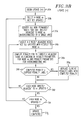
- FIG. 9 presents a method for selecting toll factors ⁇ and ⁇ based on a region-elimination optimization method such as the binary search.
- initial values for toll factors ⁇ and ⁇ are selected, typically based on experience with toll factors used previously (for example, in configuring a similar multicast conference tree). For networks containing as many as 80 nodes (of which as many as 16 may be terminating nodes) and 400 arcs, setting ⁇ equal to 1 and operating ⁇ over a range of 0 to 1024 has proven to be a reasonably successful strategy.
- a close-to-optimal Steiner tree is selected in step 904 , for example, according to the method illustrated FIGS. 3A, 3 B and 8 .
- Tree diameter td s is evaluated. If td s is equal to the end-to-end delay constraint T (within acceptable limits), the process concludes in step 908 as an acceptable tree has been selected. If td s is greater than end-to-end delay constraint T and values for toll factors ⁇ and ⁇ are at a boundary that provides maximum emphasis on delta diameter ⁇ i,j , the process moves at step 914 to expand the toll factor range and select new starting values. The process then moves to step 904 to select another minimum cost Steiner tree.
- step 916 select new toll factor values nearer a toll factor boundary that places more emphasis on delta diameter ⁇ i,j . For example, if ⁇ is set equal to 1, and ⁇ ranges from 0 to 1024 and has a current value of 512, a new value of 768 may be selected for ⁇ (halfway between the current value and the boundary placing greatest emphasis on delta diameter ⁇ i,j ).
- step 918 select new toll factor values nearer a toll factor boundary that places less emphasis on delta diameter ⁇ i,j .
- ⁇ is set equal to 1
- ⁇ may range from 0 to 1024 and has a current value of 512
- a new value of 256 may be selected for ⁇ (halfway between the current value and the boundary placing least emphasis on delta diameter ⁇ i,j ).
- equation (5) may be reformulated as:
- ⁇ is a toll factor having a value on the interval [0,1]
- Equation (6) provides the advantage of providing clear toll factor boundaries of 0 and 1 without limiting the extent to which C i, j or ⁇ i,j may be emphasized with respect to each other. For example, by selecting ⁇ equal to either 1 or 0, C Rev, i, j respectively places full emphasis on either C i, j or ⁇ i,j .
- FIG. 10 shows cost and delay for a simulated network example where C Rev, i,j sets ⁇ equal to 1.
- the simulated network contains 40 nodes (of which 8 are terminating nodes) and 200 arcs, and ⁇ ranges from 0 to 1000.
- ⁇ 0 (equivalent to no delay constraint)
- a close-to-optimal constrained Steiner tree is selected having a cost of approximately 38 units and a delay of approximately 84 units.
- ⁇ equal to 1000 a close-to-optimal constrained Steiner tree is selected having a cost of approximately 123 units and a delay of approximately 19 units.
- a reasonable compromise may be found at 1 equal to 1, where the delay is more than halved to about 37 units while cost is increased by only about 45 percent to 55 units.
- the process may be modified to determine a next lowest penalty path to the tree and continue.
- An additional embodiment of the present invention could specify that close-to-optimal Steiner trees be selected starting at each terminating node, and that the Steiner tree having the lowest penalty among these selected trees be chosen as the multicast network tree.
- Other penalty parameters that may be incrementally defined and summed to determine an overall tree penalty (for example, bandwidth capacity) may also be alternatively included as part of the penalty function C.
- Penalty parameters that may have a transform that can be summed to determine an overall tree penalty (for example, jitter) may also be considered. Additionally, multiple ones of these penalty parameters may be included in a single penalty similar to equation (5) by adding these parameters as additional terms of the equation together with appropriate toll factors.
Abstract
Description
Claims (13)
Priority Applications (1)
| Application Number | Priority Date | Filing Date | Title |
|---|---|---|---|
| US09/573,783 US6717921B1 (en) | 2000-05-17 | 2000-05-17 | Method for configuring a shared tree for routing traffic in a multicast conference |
Applications Claiming Priority (1)
| Application Number | Priority Date | Filing Date | Title |
|---|---|---|---|
| US09/573,783 US6717921B1 (en) | 2000-05-17 | 2000-05-17 | Method for configuring a shared tree for routing traffic in a multicast conference |
Publications (1)
| Publication Number | Publication Date |
|---|---|
| US6717921B1 true US6717921B1 (en) | 2004-04-06 |
Family
ID=32031103
Family Applications (1)
| Application Number | Title | Priority Date | Filing Date |
|---|---|---|---|
| US09/573,783 Expired - Lifetime US6717921B1 (en) | 2000-05-17 | 2000-05-17 | Method for configuring a shared tree for routing traffic in a multicast conference |
Country Status (1)
| Country | Link |
|---|---|
| US (1) | US6717921B1 (en) |
Cited By (16)
| Publication number | Priority date | Publication date | Assignee | Title |
|---|---|---|---|---|
| US20020029287A1 (en) * | 2000-02-02 | 2002-03-07 | Yechiam Yemini | Method and apparatus for dynamically addressing a circuits based network |
| US20040042473A1 (en) * | 2002-08-28 | 2004-03-04 | Park Hye Kyeong | Method for providing QoS (quality of service) - guaranteeing multi-path and method for providing disjoint path using the same |
| US20040218536A1 (en) * | 2002-12-11 | 2004-11-04 | Nippon Telegraph And Telephone Corp. | Multicast communication path calculation method and multicast communication path calculation apparatus |
| US20050068904A1 (en) * | 2003-09-30 | 2005-03-31 | Cisco Technology, Inc. | Managing multicast conference calls |
| US20050108071A1 (en) * | 2003-11-17 | 2005-05-19 | Kamal Jain | Systems and methods for approximating optimal distribution via networked systems |
| US6954790B2 (en) * | 2000-12-05 | 2005-10-11 | Interactive People Unplugged Ab | Network-based mobile workgroup system |
| US20070076703A1 (en) * | 2003-10-22 | 2007-04-05 | Takahiro Yoneda | Packet distribution control method |
| WO2007040292A1 (en) * | 2005-10-06 | 2007-04-12 | Egc & C Co., Ltd. | Method and system for voting optimal route in multicasting |
| US20080072184A1 (en) * | 2003-05-12 | 2008-03-20 | International Business Machines Corporation | Method of Achieving Timing Closure in Digital Integrated Circuits by Optimizing Individual Macros |
| US20080212496A1 (en) * | 2005-11-11 | 2008-09-04 | Huawei Technologies Co., Ltd. | Communication network system and signal transmission method between leaf-nodes of multicast tree and node thereof |
| US20090168775A1 (en) * | 2007-12-31 | 2009-07-02 | National Tsing Hua University of Taiwan, Republic of China | Heuristic algorithm for application-layer multicast with minimum delay |
| US20090222782A1 (en) * | 2008-03-03 | 2009-09-03 | Microsoft Corporation | Network analysis with steiner trees |
| CN102577282A (en) * | 2010-08-20 | 2012-07-11 | 松下电器产业株式会社 | Network delay estimation apparatus and network delay estimation method |
| EP2485431A1 (en) | 2007-07-27 | 2012-08-08 | Clear-Com Research Inc. | Multi-point to multi-point intercom system |
| US9337898B2 (en) | 2009-04-14 | 2016-05-10 | Clear-Com Llc | Digital intercom network over DC-powered microphone cable |
| US9639906B2 (en) | 2013-03-12 | 2017-05-02 | Hm Electronics, Inc. | System and method for wideband audio communication with a quick service restaurant drive-through intercom |
Citations (7)
| Publication number | Priority date | Publication date | Assignee | Title |
|---|---|---|---|---|
| US5291477A (en) * | 1992-08-10 | 1994-03-01 | Bell Communications Research, Inc. | Method and system for multicast routing in an ATM network |
| US5541927A (en) * | 1994-08-24 | 1996-07-30 | At&T Corp. | Method of multicasting |
| US6088333A (en) * | 1996-11-20 | 2000-07-11 | Electronics And Telecommunications Research Institute | Multicast routing method using path overlapping efficiency in VP-based on ATM networks |
| US6154463A (en) * | 1997-08-26 | 2000-11-28 | Lucent Technologies, Inc. | System and method for multicast conferencing and online discussion groups |
| US6321271B1 (en) * | 1998-12-22 | 2001-11-20 | Lucent Technologies Inc. | Constrained shortest path routing method |
| US6363319B1 (en) * | 1999-08-31 | 2002-03-26 | Nortel Networks Limited | Constraint-based route selection using biased cost |
| US6529498B1 (en) * | 1998-04-28 | 2003-03-04 | Cisco Technology, Inc. | Routing support for point-to-multipoint connections |
-
2000
- 2000-05-17 US US09/573,783 patent/US6717921B1/en not_active Expired - Lifetime
Patent Citations (7)
| Publication number | Priority date | Publication date | Assignee | Title |
|---|---|---|---|---|
| US5291477A (en) * | 1992-08-10 | 1994-03-01 | Bell Communications Research, Inc. | Method and system for multicast routing in an ATM network |
| US5541927A (en) * | 1994-08-24 | 1996-07-30 | At&T Corp. | Method of multicasting |
| US6088333A (en) * | 1996-11-20 | 2000-07-11 | Electronics And Telecommunications Research Institute | Multicast routing method using path overlapping efficiency in VP-based on ATM networks |
| US6154463A (en) * | 1997-08-26 | 2000-11-28 | Lucent Technologies, Inc. | System and method for multicast conferencing and online discussion groups |
| US6529498B1 (en) * | 1998-04-28 | 2003-03-04 | Cisco Technology, Inc. | Routing support for point-to-multipoint connections |
| US6321271B1 (en) * | 1998-12-22 | 2001-11-20 | Lucent Technologies Inc. | Constrained shortest path routing method |
| US6363319B1 (en) * | 1999-08-31 | 2002-03-26 | Nortel Networks Limited | Constraint-based route selection using biased cost |
Non-Patent Citations (6)
| Title |
|---|
| Ahn A multicast tree algorithm considering maximum delay bound for real-time applications. Local Computer Networks, 1996., Proceedings 21st IEEE Conference on, Oct. 13-16, 1996 Page(s): 172-181.* * |
| Ahuja, Ravindra K., et al., Network Flows: Theory, Algorithms and Applications, Prentice Hall, Englewood Cliffs, NJ, 1993, pp. 598-638. |
| Kompella, Vachaspathi P., et al., "Multicast Routing for Multimedia Communication," IEEE/ACM Transactions on Networking, Vol, 1, No. 3, Jun. 1993, pp. 286-292. |
| Maxemchuk, Nicholas F., "Video Distribution on Multicast Networks," IEEE Journal on Selected Areas in Communications, vol. 15, No. 3, Apr. 1997, pp. 357-372. |
| Paul, Sanjoy, Multicasting on the Internet and its Applications, Kluwer Academic Publishers, Boston, MA, 1998, pp. 21-28 and 397-415. |
| Ravindran Cost-optimal multicast trees for multi-source data flows in multimedia distribution. INFOCOM 2001. Twentieth Annual Joint Conference of the IEEE Computer and Communications Societies. Proceedings. IEEE, vol.: 2, 22-26 Apr. 2.* * |
Cited By (36)
| Publication number | Priority date | Publication date | Assignee | Title |
|---|---|---|---|---|
| US20020029287A1 (en) * | 2000-02-02 | 2002-03-07 | Yechiam Yemini | Method and apparatus for dynamically addressing a circuits based network |
| US20020028656A1 (en) * | 2000-02-02 | 2002-03-07 | Yechiam Yemini | Method and apparatus for providing forwarding and replication services on a dynamically addressed network |
| US20020031131A1 (en) * | 2000-02-02 | 2002-03-14 | Yechiam Yemini | Method and apparatus for the exchange of data between a dynamically addressed network and a foreign network |
| US20020091855A1 (en) * | 2000-02-02 | 2002-07-11 | Yechiam Yemini | Method and apparatus for dynamically addressing and routing in a data network |
| US20020163889A1 (en) * | 2000-02-02 | 2002-11-07 | Yechiam Yemini | Method and apparatus for providing services on a dynamically addressed network |
| US6954790B2 (en) * | 2000-12-05 | 2005-10-11 | Interactive People Unplugged Ab | Network-based mobile workgroup system |
| US20040042473A1 (en) * | 2002-08-28 | 2004-03-04 | Park Hye Kyeong | Method for providing QoS (quality of service) - guaranteeing multi-path and method for providing disjoint path using the same |
| US7366114B2 (en) * | 2002-08-28 | 2008-04-29 | Electronics And Telecommunications Research Institute | Method for providing QoS (quality of service)—guaranteeing multi-path and method for providing disjoint path using the same |
| US20040218536A1 (en) * | 2002-12-11 | 2004-11-04 | Nippon Telegraph And Telephone Corp. | Multicast communication path calculation method and multicast communication path calculation apparatus |
| US7652998B2 (en) * | 2002-12-11 | 2010-01-26 | Nippon Telegraph And Telephone Corporation | Multicast communication path calculation method and multicast communication path calculation apparatus |
| US7743355B2 (en) * | 2003-05-12 | 2010-06-22 | International Business Machines Corporation | Method of achieving timing closure in digital integrated circuits by optimizing individual macros |
| US20080072184A1 (en) * | 2003-05-12 | 2008-03-20 | International Business Machines Corporation | Method of Achieving Timing Closure in Digital Integrated Circuits by Optimizing Individual Macros |
| WO2005036788A3 (en) * | 2003-09-30 | 2006-01-12 | Cisco Tech Ind | Managing multicast conference calls |
| US20050068904A1 (en) * | 2003-09-30 | 2005-03-31 | Cisco Technology, Inc. | Managing multicast conference calls |
| US7453826B2 (en) * | 2003-09-30 | 2008-11-18 | Cisco Technology, Inc. | Managing multicast conference calls |
| US20070076703A1 (en) * | 2003-10-22 | 2007-04-05 | Takahiro Yoneda | Packet distribution control method |
| US7580368B2 (en) * | 2003-10-22 | 2009-08-25 | Panasonic Corporation | Packet distribution control method |
| US20050108071A1 (en) * | 2003-11-17 | 2005-05-19 | Kamal Jain | Systems and methods for approximating optimal distribution via networked systems |
| US20090190586A1 (en) * | 2005-10-06 | 2009-07-30 | Yong-Hwa Kim | Method and system for voting optimal route in multicasting |
| WO2007040292A1 (en) * | 2005-10-06 | 2007-04-12 | Egc & C Co., Ltd. | Method and system for voting optimal route in multicasting |
| CN101305552B (en) * | 2005-10-06 | 2010-08-18 | 株式会社Egc&C | Method and system for voting optimum route in multicast |
| US20080212496A1 (en) * | 2005-11-11 | 2008-09-04 | Huawei Technologies Co., Ltd. | Communication network system and signal transmission method between leaf-nodes of multicast tree and node thereof |
| EP2485431A1 (en) | 2007-07-27 | 2012-08-08 | Clear-Com Research Inc. | Multi-point to multi-point intercom system |
| US20090168775A1 (en) * | 2007-12-31 | 2009-07-02 | National Tsing Hua University of Taiwan, Republic of China | Heuristic algorithm for application-layer multicast with minimum delay |
| US20090222782A1 (en) * | 2008-03-03 | 2009-09-03 | Microsoft Corporation | Network analysis with steiner trees |
| WO2009111217A2 (en) * | 2008-03-03 | 2009-09-11 | Microsoft Corporation | Network analysis with steiner trees |
| WO2009111217A3 (en) * | 2008-03-03 | 2009-11-12 | Microsoft Corporation | Network analysis with steiner trees |
| US7885269B2 (en) | 2008-03-03 | 2011-02-08 | Microsoft Corporation | Network analysis with Steiner trees |
| US9337898B2 (en) | 2009-04-14 | 2016-05-10 | Clear-Com Llc | Digital intercom network over DC-powered microphone cable |
| CN102577282A (en) * | 2010-08-20 | 2012-07-11 | 松下电器产业株式会社 | Network delay estimation apparatus and network delay estimation method |
| EP2538622A1 (en) * | 2010-08-20 | 2012-12-26 | Panasonic Corporation | Network delay estimation apparatus and network delay estimation method |
| US8812663B2 (en) * | 2010-08-20 | 2014-08-19 | Panasonic Corporation | Network delay estimation apparatus and a network delay estimation method |
| EP2538622A4 (en) * | 2010-08-20 | 2014-09-24 | Panasonic Corp | Network delay estimation apparatus and network delay estimation method |
| US20120198060A1 (en) * | 2010-08-20 | 2012-08-02 | Panasonic Corporation | network delay estimation apparatus and a network delay estimation method |
| CN102577282B (en) * | 2010-08-20 | 2017-08-25 | 松下知识产权经营株式会社 | Network delay estimation unit and network delay method of estimation |
| US9639906B2 (en) | 2013-03-12 | 2017-05-02 | Hm Electronics, Inc. | System and method for wideband audio communication with a quick service restaurant drive-through intercom |
Similar Documents
| Publication | Publication Date | Title |
|---|---|---|
| US6717921B1 (en) | Method for configuring a shared tree for routing traffic in a multicast conference | |
| Deering et al. | Multicast routing in datagram internetworks and extended LANs | |
| US7002917B1 (en) | Method for path selection in a network | |
| AU719658B2 (en) | A dynamic distributed multicast routing protocol | |
| Helder et al. | End-host multicast communication using switch-trees protocols | |
| US5535195A (en) | Method for efficient aggregation of link metrics | |
| US20050094577A1 (en) | Virtual private networks within a packet network having a mesh topology | |
| US20100027442A1 (en) | Constructing scalable overlays for pub-sub with many topics: the greedy join-leave algorithm | |
| JP4387519B2 (en) | Effective means for accumulating multicast trees | |
| Birrer et al. | FatNemo: Building a resilient multi-source multicast fat-tree | |
| US8510365B2 (en) | Method for optimising the distribution of a service from a source to a plurality of clients in a network | |
| Westcott et al. | Hierarchical routing for very large networks | |
| US6661789B1 (en) | Dynamic burstification based on fully/partially shared multicast entities | |
| Jiang et al. | FloodTrail: an efficient file search technique in unstructured peer-to-peer systems | |
| Jiang | Routing broadband multicast streams | |
| Shacham | Multicast routing of hierarchical data | |
| McQuillan | Enhanced message addressing capabilities for computer networks | |
| Gangulay et al. | Optimal routing for fast transfer of bulk data files in time-varying networks | |
| Moh et al. | QoS-guaranteed one-to-many and many-to-many multicast routing | |
| Aggarwal et al. | Constrained diameter steiner trees for multicast conferences in overlay networks | |
| Moh et al. | An optimal QoS-guaranteed multicast routing algorithm with dynamic membership support | |
| Hać et al. | A new heuristic algorithm for finding minimum‐cost multicast trees with bounded path delay | |
| Auerbach et al. | Multicast group membership management in high speed wide area networks | |
| Low et al. | Dynamic group multicast routing with bandwidth reservations | |
| Li et al. | QoS multicast routing protocol in hierarchical wireless MANET |
Legal Events
| Date | Code | Title | Description |
|---|---|---|---|
| AS | Assignment |
Owner name: LUCENT TECHNOLOGIES, INC., NEW JERSEY Free format text: ASSIGNMENT OF ASSIGNORS INTEREST;ASSIGNORS:AGGARWAL, SUDHIR;NETRAVALI, ARUN;SABNANI, KRISHAN K.;REEL/FRAME:010833/0421;SIGNING DATES FROM 20000417 TO 20000512 |
|
| FEPP | Fee payment procedure |
Free format text: PAYOR NUMBER ASSIGNED (ORIGINAL EVENT CODE: ASPN); ENTITY STATUS OF PATENT OWNER: LARGE ENTITY |
|
| STCF | Information on status: patent grant |
Free format text: PATENTED CASE |
|
| FPAY | Fee payment |
Year of fee payment: 4 |
|
| FPAY | Fee payment |
Year of fee payment: 8 |
|
| AS | Assignment |
Owner name: CREDIT SUISSE AG, NEW YORK Free format text: SECURITY INTEREST;ASSIGNOR:ALCATEL-LUCENT USA INC.;REEL/FRAME:030510/0627 Effective date: 20130130 |
|
| AS | Assignment |
Owner name: ALCATEL-LUCENT USA INC., NEW JERSEY Free format text: RELEASE BY SECURED PARTY;ASSIGNOR:CREDIT SUISSE AG;REEL/FRAME:033949/0531 Effective date: 20140819 |
|
| FPAY | Fee payment |
Year of fee payment: 12 |
|
| AS | Assignment |
Owner name: WSOU INVESTMENTS, LLC, CALIFORNIA Free format text: ASSIGNMENT OF ASSIGNORS INTEREST;ASSIGNOR:ALCATEL-LUCENT USA INC.;REEL/FRAME:045089/0972 Effective date: 20171222 |
|
| AS | Assignment |
Owner name: OT WSOU TERRIER HOLDINGS, LLC, CALIFORNIA Free format text: SECURITY INTEREST;ASSIGNOR:WSOU INVESTMENTS, LLC;REEL/FRAME:056990/0081 Effective date: 20210528 |