US6724507B1 - Image processing method and image processing apparatus - Google Patents

Image processing method and image processing apparatus Download PDF

Info

Publication number
US6724507B1
US6724507B1 US09/345,783 US34578399A US6724507B1 US 6724507 B1 US6724507 B1 US 6724507B1 US 34578399 A US34578399 A US 34578399A US 6724507 B1 US6724507 B1 US 6724507B1
Authority
US
United States
Prior art keywords
point
color gamut
conversion
input
correction
Prior art date
Legal status (The legal status is an assumption and is not a legal conclusion. Google has not performed a legal analysis and makes no representation as to the accuracy of the status listed.)
Expired - Fee Related
Application number
US09/345,783
Inventor
Hiroaki Ikegami
Hitoshi Ogatsu
Ryosuke Higashikata
Takahide Inoue
Current Assignee (The listed assignees may be inaccurate. Google has not performed a legal analysis and makes no representation or warranty as to the accuracy of the list.)
Fujifilm Business Innovation Corp
Original Assignee
Fuji Xerox Co Ltd
Priority date (The priority date is an assumption and is not a legal conclusion. Google has not performed a legal analysis and makes no representation as to the accuracy of the date listed.)
Filing date
Publication date
Application filed by Fuji Xerox Co Ltd filed Critical Fuji Xerox Co Ltd
Assigned to FUJI XEROX CO., LTD. reassignment FUJI XEROX CO., LTD. ASSIGNMENT OF ASSIGNORS INTEREST (SEE DOCUMENT FOR DETAILS). Assignors: HIGASHIKATA, RYOSUKE, IKEGAMI, HIROAKI, INOUE, TAKAHIDE, OGATSU, HITOSHI
Application granted granted Critical
Publication of US6724507B1 publication Critical patent/US6724507B1/en
Anticipated expiration legal-status Critical
Expired - Fee Related legal-status Critical Current

Links

Images

Classifications

    • HELECTRICITY
    • H04ELECTRIC COMMUNICATION TECHNIQUE
    • H04NPICTORIAL COMMUNICATION, e.g. TELEVISION
    • H04N1/00Scanning, transmission or reproduction of documents or the like, e.g. facsimile transmission; Details thereof
    • H04N1/46Colour picture communication systems
    • H04N1/56Processing of colour picture signals
    • H04N1/60Colour correction or control
    • H04N1/6058Reduction of colour to a range of reproducible colours, e.g. to ink- reproducible colour gamut

Definitions

  • the present invention concerns an image processing method and an image processing apparatus for compressing or expanding a color gamut of a color input image or a partial region thereof in accordance with the color gamut of a color image output apparatus such as a color printer or a color display.
  • a color image output apparatus such as color printers or color displays cannot reproduce all of visually perceptible colors and can reproduce those colors within a limited range referred to as a color gamut.
  • colors out of the color gamut of the output apparatus may possibly be inputted as input images, in which processing for converting the input image within the color gamut of the output apparatus, that is, processing of compressing the color gamut of the input image (color expression range) within the color gamut of the output apparatus.
  • the input image is contained within the color gamut of the output apparatus, it is possible to conduct a processing referred to as color gamut expansion of converting the input image to an image of higher quality by effectively utilizing the color gamut of the output apparatus, for example, by making the chroma higher.
  • Perceptual is a method of changing not only the colors out of the color gamut but also the colors within the color gamut of the output apparatus using a predetermined ratio while keeping hues and compressing the color gamut toward a fixed point on a gray axis within the color gamut of the output apparatus.
  • Saturation is a method of clipping only the colors out of the color gamut of the output apparatus to the color gamut surface of the output apparatus toward a fixed point on a gray axis within the color gamut of the output apparatus while keeping the hue.
  • Colorimetric is a method of clipping only the colors out of the color gamut of the output apparatus to the color gamut surface of the output apparatus toward a gray axis in the color gamut of the output apparatus while preserving the lightness and the hue.
  • Perceptual compresses the input image always using a predetermined ratio irrespective of the hue and the lightness of the input image it involves a problem of compressing also the colors in the region of hue or lightness not requiring compression.
  • Saturation and Colorimetric also clip the colors out of the color gamut of the output apparatus to the color gamut surface of the output apparatus irrespective of the hue and the lightness of the input image, they involve a problem that when a color similar to the color after converting the color out of the color gamut of the output apparatus to the color gamut surface of the output apparatus is present in the input image of the original image in the color gamut of the output apparatus, distinguishability between the both colors is deteriorated and, if there is a gradation outside of the color gamut of the output apparatus, the gradation may possibly be lost by the processing.
  • the Saturation or Colorimetric is attained by a multi-dimensional DLUT interpolating calculation type color converter adapted to retrieve a multi-dimensional DLUT (Direct Look Up Table) using upper bits of the input image data as the address, and obtaining output image data by interpolating calculation of the thus read out lattice point data by using lower bits in the input image data
  • the lattice point data is defined by clipping the lattice point data out of the color gamut of the output apparatus to the color gamut surface of the output apparatus, it gives rise to a problem that colors in the color gamut and in the vicinity of the color gamut surface of the output apparatus are also compressed unnecessarily.
  • Japanese Published Unexamined Patent Application No. Hei 7-203234 discloses a method of dividing an uniform color space into unitary regions, determining the number of pixels contained in the input image on every unitary region and mapping an image to other unitary regions of an equal lightness in accordance with the number of pixels for the unitary region out of the color gamut of the output apparatus.
  • Japanese Published Unexamined Patent Application No. Hei 7-203234 discloses processing by dividing a color gamut into small blocks as a method of color gamut compression corresponding to visual bending of hue lines in a color stage as reported, for example, in articles 4-1 of Color Forum Japan 95 (p. 45-48) in addition to the problems described above.
  • the method involves a problem of being incapable of correcting with visual bending of hue lines within a small block and incapable of ensuring continuity between the blocks.
  • Another object of the present invention is to enable correction for visual bending caused by distortion of a color space in each of the regions of the color space.
  • an image processing method comprising:
  • an output color gamut point calculation step of determining an output color gamut point as an intersection between a base line that is a line extending from the fixed point in the color gamut of the output apparatus to the conversion target point and an output color gamut surface itself or a closed curved surface inside the color gamut of the output apparatus;
  • an input color gamut point calculation step of determining an input color gamut point as an intersection between the base line and an color gamut surface of the input image or the partial region thereof;
  • a first conversion point calculation step of determining a first conversion point on the base line using the fixed point, the output color gamut point and a first weighing coefficient
  • a second conversion point calculation step of determining a second conversion point by using correction data for correcting the compressing direction or expanding direction and the first weighing coefficient
  • a final conversion point calculation step of determining a final conversion point for the conversion target point by using the first conversion point, the second conversion point and a second weighing coefficient.
  • a correction point calculation step of calculating a correction point by correcting a conversion target point using a correction data corresponding to the conversion target point
  • an output color gamut point and an input color gamut point as intersections between a base line extending from a fixed point to a conversion target point and an output color gamut surface and an input color gamut surface are determined, and then a first conversion point is determined as a point on the base line in the hue keeping direction on one hand and a second conversion point is determined which can be a direction for changing the hue on the other hand, and a final conversion point is determined as a point on a segment connecting the first conversion point and the second conversion point.
  • the region requiring the color gamut compression can be put to color gamut compression depending on the distribution of the input image by the setting for the first weighing coefficient, the correction data and the second weighing coefficient, the direction of the color gamut compression can be controlled continuously for each of the regions, and the amount of the color gamut compression including clipping can also be controlled continuously. Further, by the same setting, excessively unnecessary color gamut compression can be avoided, particularly, upon clipping in a case of conducting color gamut compression by a color converter of a multi-dimensional DLUT interpolating calculation type.
  • the visual bending of the hue lines in the color space can be compensated in each of the region of the color space.
  • a final conversion point can be obtained on an ideal conversion curve passing the conversion target point and the fixed point by calculating a correction point by applying correction data corresponding to the conversion target point, determining the conversion point by compressing or expanding the correction point along a line passing through the correction point and a fixed point that is determined uniquely based on the conversion target point and calculating the final conversion point by conducting correction to the conversion point by the inverse correction data corresponding to the conversion point.
  • FIG. 1 is a view for explaining a method of processing an image according to a first invention
  • FIG. 2 is a view for explaining a method of processing an image according to a first invention
  • FIG. 3 is a view showing an example of setting a fixed point
  • FIG. 4 is a view showing an example of setting a fixed point
  • FIG. 5 is a view showing an example of setting an output color gamut surface:
  • FIG. 6 is a view showing a first embodiment of the image processing method according to the present invention.
  • FIG. 7 is a view showing an example of an output color gamut point calculation step
  • FIG. 8 is a view showing an example of an input color gamut point calculation step
  • FIG. 9 is a view showing an example of an input color gamut point calculation step
  • FIG. 10 is a view showing an example of a shape of a function used for deciding a first weighing coefficient:
  • FIG. 11 is a view showing an example of a shape of a function used for deciding a first weighing coefficient:
  • FIG. 12 is a view showing an example of a shape of a function used for deciding a second weighing coefficient:
  • FIG. 13 is a view showing a second conversion point calculation step
  • FIG. 14 is a view showing a second conversion point calculation step
  • FIG. 15 is a view showing a second embodiment of the image processing method according to the present invention.
  • FIG. 16 is a view showing a first embodiment of an image processing apparatus according to the present invention.
  • FIG. 17 is a view showing a second embodiment of the image processing apparatus according to the present invention.
  • FIG. 18 is a view for explaining a method of processing images according to a third invention.
  • FIG. 19 is a view for explaining a method of processing images according to a third invention.
  • FIG. 20 is a view showing a third embodiment of the image processing method according to the present invention.
  • FIG. 21 is a view for explaining correction data in the image processing method according to the third invention.
  • the present invention is to be explained by way of preferred embodiments in a case of conducting color gamut compression or color gamut expansion to a color input image (hereinafter simply referred to as an input image) or a partial region thereof on a CIELAB (L*a*b*) color space as an example.
  • an input image hereinafter simply referred to as an input image
  • a partial region thereof on a CIELAB (L*a*b*) color space as an example.
  • the present invention is applicable also to other color spaces such as CIELUV (L*u*v*), YIQ, YCbCr, XYZ and RGB.
  • FIG. 1 and FIG. 2 show a CIELAB color space in a two-dimensional manner by an L* axis as a lightness axis and C* axis as a chroma axis for the sake of convenience.
  • a point P 0 in a color gamut of a color image output apparatus (hereinafter simply referred to as an output apparatus), and the point is set on a gray axis, that is, on the L* axis in the CIELAB color space as described later.
  • the fixed point means hereinafter the fixed point P 0 in the color gamut of the output apparatus.
  • a point P 1 is a conversion target point represented by a color coordinate value of an input image or a partial region thereof.
  • a line L 1 is a line extending from the fixed point P 0 to the conversion target point P 1 and is defined as a base line.
  • a surface (curved surface) C 2 is an output color gamut surface itself of an output apparatus or a closed curved surface inside the color gamut of the output apparatus to be set as will be described later and is defined as an output color gamut surface.
  • a surface C 3 is an color gamut surface of the input image or a partial region thereof and is defined as an input color gamut surface.
  • FIG. 1 and FIG. 2 show a case in which the input color gamut surface C 3 is at the outside of the output color gamut surface C 2 and the conversion target point P 1 is converted by compression.
  • the method of the present invention is also applicable to a case in which the output color gamut surface C 2 is at the outside of the input color gamut surface C 3 and the conversion target point P 1 is converted by expansion.
  • a point P 2 is an intersection between the base line L 1 and the output color gamut surface C 2 and is defined as an output color gamut point.
  • a point P 3 is an intersection between the base line L 1 and the input color gamut surface C 3 and is defined as an input color gamut point.
  • a point P 4 is a first conversion point which is determined by weighted mean of the fixed point P 0 and the output color gamut point P 2 using a first weighing coefficient. Accordingly, the first conversion point P 4 is a point on the base line L 1 .
  • a point P 5 is a second conversion point which is determined by using correction data for correcting the compressing direction or the expanding direction using the first weighing coefficient.
  • a line L 5 is a line extending from the fixed point P 0 to a second conversion point P 5 and is defined as a correction line.
  • the correction line L 5 is different from the base line L 1 but, if the correction data is zero, the correction line L 5 agrees with the base line 11 .
  • the correction data is set and prepared as discrete data in the color space as shown, for example, in FIG. 1 and FIG. 2 as correction data D 1 .
  • a point P 6 is a final conversion point for the conversion target point P 1 and is determined by weighted means of the first conversion point P 4 and the second conversion point P 5 by using a second weighing coefficient. Accordingly, the final conversion point P 6 is a point on a segment connecting the first conversion point P 4 with the second conversion point P 5 .
  • FIG. 18 shows a CIELAB color space in a two-dimensional manner by using L* axis as a lightness axis and C* axis as a chroma axis
  • FIG. 19 shows a CIELAB color space in a two-dimensional manner by using a* axis and b* axis.
  • a point P 0 , a point P 1 , a curved surface C 2 and a curved surface C 3 are, respectively, a fixed point, a conversion target point, an output color gamut surface and an input color gamut surface.
  • a point P 21 is a point calculated by applying correction data corresponding to the conversion target point P 1 relative to the conversion target point P 1 and is defined as a correction point.
  • the correction data is provided as discrete vector data in the color space, and correction data corresponding to a necessary point can be calculated, for example, by interpolation.
  • a line L 2 is a line connecting the correction point P 21 with the fixed point P 0 and is defined as a correction base line.
  • a curve L 3 is a curve passing the conversion target point P 1 and the fixed point P 0 and is defined as an assumed conversion line.
  • the correction data described above is calculated based on the assumed conversion line.
  • the assumed conversion line is determined depending on the purpose and an iso-hue line passing the conversion target point P 1 and the fixed point P 0 is the assumed conversion line in a case, for example, of intending to correct bending of the hue line.
  • a point P 22 is an intersection between a correction base line L 2 and the input color gamut surface C 3 and is defined as an input color gamut point.
  • a point P 23 is an intersection between the correction base line and the output color gamut surface C 2 and is defined as an output color gamut point.
  • a point P 24 is a point obtained by compression or expansion corresponding to the color gamut of the output apparatus to the correction point P 21 along the correction base line L 2 and is defined as a conversion point.
  • the compression or expansion processing corresponding to the color gamut of the output apparatus may be conducted by using the first weighing coefficient decided based on the fixed point P 0 , the input color gamut point P 22 , the output color gamut point P 23 and the correction point P 21 , or may be conducted by an existing method.
  • a point P 25 is a final conversion point for the conversion target point P 1 and is calculated by applying inverse correction data corresponding to the conversion point P 24 .
  • the inverse correction data is formed by replacing a start point and an end point of a vector of the correction data to each other.
  • FIG. 1 Other points, surfaces and curves shown in FIG. 1, FIG. 2, FIG. 18 and FIG. 19 will be described later.
  • the second invention will also be described later.
  • the fixed point P 0 is set as a point fixed on a gray axis in a color gamut of the output apparatus, as a point changing continuously as a function of lightness, chroma and the like of the conversion target point P 1 or as a point changing discretely in accordance with lightness, chroma and the like of the conversion target point P 1 .
  • FIG. 3 shows an example of the fixed point P 0 that changes continuously as a function of lightness, chroma and the like of the conversion target point P 1 .
  • This shows a relation between an angle ⁇ and an L* value of the fixed point P 0 , assuming an angle made by a vector extending from the conversion target point P 1 to the fixed point P 0 relative to an a*b* plane as ⁇ .
  • the relation between the fixed point P 0 and the conversion target point P 1 is, for example, as shown in FIG. 4 .
  • the fixed point When the fixed point is set as a point changing continuously as a function of the lightness, chroma and the like of the conversion target point P 1 or as a point changing discretely in accordance with the lightness, chroma and the like of the conversion target point P 1 as described above, it is necessary that the base line L 1 extending from the fixed point P 0 to the conversion target point P 1 does not intersect for the entire region in the color space as shown in FIG. 4 . If the condition is not satisfied, a gradation may possibly be inverted upon compression or expansion.
  • the gradation is not inverted if the angle ⁇ is 0°.
  • angle ⁇ is other than the 0°, the gradation tends to be inverted at a high possibility and, if the lightness of the conversion target point P 1 is out of the color gamut of the output apparatus, it is difficult to set the fixed point P 0 in the color gamut of the output apparatus.
  • the fixed point P 0 is set while taking them into consideration.
  • the output color gamut surface C 2 may usually be an color gamut surface for the color gamut of the output device. However, in a case where an output apparatus is a display or the like and white points of the input image are different from the white points of the output apparatus, it may sometimes be desirable that a closed curved surface inside the color gamut of the output apparatus is the output color gamut surface C 2 .
  • FIG. 5 schematically shows an example of a relation between a color gamut of an input image or a partial region thereof and a color gamut of an output apparatus, in which a curved surface C 20 is a color gamut surface itself of an output apparatus, a surface C 3 is an input color gamut surface, that is, a color gamut surface of an input image or a partial region thereof.
  • a surface containing only the region of lower lightness than the white point compressed point P 6 w as a closed curved surface in the color gamut of the output apparatus may be set and used as the output color gamut surface C 2 .
  • a closed curved surface C 21 extended horizontally starting from the white point compressed point P 6 w such that the lightness is equal to that of the white point compressed point P 6 w, or a closed curved surface C 22 that gradually lowers the lightness as the chroma increases starting from the white point compressed point P 6 w is set as the closed curved surface in the color gamut of the output apparatus and used as an output color gamut surface C 2 .
  • FIG. 6 shows a preferred embodiment of the first invention of determining a point in an input image or a partial region thereof, namely, a color coordination value for one pixel as the conversion target point P 1 and converting the same into the final conversion point P 6 of a color coordinate value adaptable to the color gamut of the output apparatus.
  • the method shown in FIG. 6 can be attained in a computer by means of a processing program but a portion of the steps can be executed also by hardware.
  • This method comprises, as a whole, an output color gamut point calculation step 10 , an input color gamut point calculation step 20 , a first weighing coefficient deciding step 30 , a second weighing coefficient deciding step 40 , a first conversion point calculation step 50 , a second conversion point calculation step 60 and a final conversion point calculation step 70 .
  • the output color gamut point calculation step 10 or the input color gamut calculation step 20 for example, the output color gamut calculation step 10 is conducted.
  • information S 2 for the output color gamut point P 2 as an intersection between the base line L 1 , namely, a line extending from the fixed point P 0 to the conversion target point P 1 and the output color gamut surface C 2 is calculated based on the information (color coordinate value) S 1 for the conversion target point P 1 , information (color coordinate value) S 0 for the fixed point P 0 , information SC 2 for the output color gamut surface C 2 and an output profile point calculation parameter PP 2 .
  • FIG. 7 shows a concrete example of the output color gamut point calculation step 10 .
  • information (color coordinate value) S 12 for a plurality of output color gamut representative points C 12 as shown in FIG. 1 and FIG. 2 is calculated based on the output color gamut surface information SC 2 in the output color gamut representative point preparing step 11 .
  • the output color gamut surface information SC 2 is for the discrete data on the relation between the input signal and the output color depending on the output apparatus, as well as the shape of the output color gamut surface C 2 if this is a closed curved surface in the color gamut of the output apparatus.
  • data set for various YMC(K)% and LAB data may be provided, for example, when the output apparatus is a printer, or data set for various RGB and LAB data or XYZ may be provided when the output apparatus is a display.
  • a value to be predicted is set corresponding to a point on the color gamut surface of the output apparatus, and a color is predicted.
  • Setting of the value to be predicted to the point on the color gamut surface of the output apparatus corresponds to the provision of data comprising a combination of M% and C% when Y% is zero, a combination of C% and Y% when M% is zero and a combination of Y% and M% when C% is zero when the output apparatus is, for example, a three color printer.
  • the output color gamut surface C 2 is a closed curved surface of the output apparatus
  • the color data on the color gamut surface in of the output apparatus is modified by using information regarding the shape thereof to form an output color gamut representative point information S 12 .
  • the prediction method it is possible to use a method of predicting any color outputted from an input signal of any input signal depending on the output apparatus information based on the discrete data pair regarding the relation between the input signal and the output color depending on the output apparatus.
  • a known method can be utilized.
  • accurate predicting can be conducted by using a method proposed in Japanese Patent Application No. Hei 9-4949 (filed on Jan. 14, 1996).
  • the method of Japanese Patent Application No. Hei 9-4949 comprises linking a relation between an input signal and an output signal by means of a linear matrix equation including constant terms, and determining the weighing coefficient, the coefficient of the matrix equation and the predicted value successively by an approximate method so as to minimize the sum of squares for the output prediction value determined from a plurality of real input signal data items by using the matrix equation and the weighed Euclid distance of a plurality of real output signal data corresponding thereto.
  • the conversion target point information S 1 and the output color gamut representative point information S 12 are converted into the polar coordinate with the fixed point P 0 as the center, respectively, based on the fixed point information S 0 in the polar coordinate conversion step 12 to obtain a conversion target point polar coordinate information S 1 r and an output color gamut representative point polar coordinate information S 12 r.
  • information (color coordinate value) S 2 for the output color gamut point P 2 is calculated based on the conversion target point polar coordinate information S 1 r , the output color gamut representative point polar coordinate information S 12 r and the output color gamut point calculation parameter PP 2 .
  • calculation for an intersection between the base line L 1 and the output color gamut surface C 2 corresponds to predicting of the prediction value (ro) as a value to be predicted ( ⁇ o, ⁇ o) based on N units of the data pair of ( ⁇ i ⁇ i) and ri. Accordingly, calculation can be conducted by using the known method or the method of the prior application.
  • the output color gamut calculation parameter PP 2 may be determined in accordance with the number of the output color gamut representative points P 12 while taking care of the continuity for ⁇ , ⁇ , for example, continuity between 0° and 360° of ⁇ .
  • information S 3 for the input color gamut point P 3 as an intersection between the base line L 1 and the input color gamut surface C 3 is calculated in the input color gamut point calculation step 20 , based on the conversion target point information S 1 , the fixed point information S 0 , the pixel value information S 20 for the input image or the partial region thereof, and the parameter PP 3 for input color gamut point calculation.
  • Individual pixel values per se of the input image or the partial region thereof may be used as the pixel value information S 20 of the input image or the partial region thereof.
  • the color gamut of the input image or the partial region thereof is previously assumed, for example, as an NTSCRGB color gamut, an SRGB color gamut or a color gamut represented by YMCBRGWK color coordinate points, discrete color coordinate information located at the color gamut portion of the assumed color gamut may be used.
  • the input color gamut representative point candidate selection step and the input color gamut representative point selection step shown below can be saved.
  • FIG. 8 and FIG. 9 show, respectively, concrete examples of the input color gamut provided point calculation step 20 .
  • FIG. 8 is an example of selecting the input color gamut representative points from all pixel values of the input image or the partial region thereof and
  • FIG. 9 is an example of determining the input color gamut representative candidates, for example, by thinning pixels of the input image or the partial region thereof and selecting the input color gamut representative point from the input color gamut representative point candidates.
  • pixel value information S 20 of the input image or the partial region thereof is at first converted into the polar coordination with the fixed point P 0 as the center based on the fixed point information S 0 in the polar coordinate conversion step 22 to obtain pixel value polar coordinate information S 20 r.
  • the conversion target point information S 1 is also converted into the polar coordinate with the fixed point P 0 as the center based on the fixed point information S 0 , to obtain a conversion target point polar coordinate information S 1 r. Since this has already been calculated in the polar coordinate conversion step 12 in the output color gamut point calculation step 10 shown in FIG. 7, this result may be utilized.
  • information S 13 for the input color gamut representative points P 13 as the discrete points in the color gamut surface C 3 as shown in FIG. 1 and FIG. 2 are selected from the pixel value polar coordinate information S 20 r in the input color gamut representative point selection step 23 .
  • information (color coordinate value) S 3 for the input color gamut point P 3 as an intersection between the base line L 1 and the input color gamut surface C 3 is calculated based on the conversion target point polar coordinate information S 1 r, the input color gamut representative point information S 13 and the input color gamut point calculation parameter PP 3 .
  • the input color gamut point calculation parameter PP 3 may be determined in accordance with the number of the input color gamut representative points P 13 while taking care of the continuity between 0° and 360° for 74 , ⁇ .
  • the input color gamut surface C 3 as the color gamut surface for the color gamut of the input image or the partial region thereof may sometimes has remarkable unevenness compared with the case of calculating the output color gamut information S 2 , it is important in this case to set the parameter PP 3 for the input color gamut point calculation so as to strengthen the smoothing effect.
  • the information S 21 for the input color gamut representative point candidates is obtained at first in the input color gamut representative point candidate selection step 21 from the pixel value information 20 of the input image or the partial region thereof.
  • the input color gamut representative point When the input color gamut representative point is selected from the pixel value information S 20 per se of the input image or the partial region thereof as in the example shown in FIG. 8, it takes much time for the processing in the polar coordinate conversion step 22 and the input color gamut representative point selection step 23 . However, when the input color gamut representative point candidate is previously selected at the input color gamut representative point candidate selection step 21 as in the example shown in FIG. 9, the processing time in the subsequent polar coordinate conversion step 22 and the input color gamut representative point selection step 23 can be shortened.
  • a method for example, of merely thinning pixels of the input image or the partial region thereof or determining a mean value for several pixels and determining the mean value as the input color gamut representative point candidate information S 21 can be used.
  • information SW 1 for a first weighing coefficient used in the subsequent first conversion point calculation step 50 and the second conversion step calculation step 60 is calculated next in the first weighing efficient deciding step 30 based on the conversion target point information S 1 , the fixed point information S 0 , the output color gamut point information S 2 , the input color gamut point information S 3 and the first weighing coefficient deciding parameter PW 1 .
  • the first weighing coefficient deciding step 30 the first weighing coefficient is decided by conducting 1-variable function calculation of inputting a ratio between a distance from the fixed point to the conversion target point and a distance from the fixed point to the input color gamut point and outputting the first weighing coefficient.
  • the shape of the 1-variable function will be explained with reference to FIG. 10 and FIG. 11 .
  • FIG. 10 shows a shape of a 1-variable function in a case where a ratio R 2 between the distance from the fixed point to the output color gamut point and the distance from the fixed point to the input color gamut point is 1 or less, namely, when compression is conducted as shown in FIG. 1 and FIG. 2 .
  • the shape is determined based on at least two parameters comprising a first parameter that is a first weighing coefficient W 1 when the ratio R 2 between the distance from the fixed point to the output color gamut point and the distance from the fixed point to the input color gamut point is an input (ratio between the distance from the fixed point to the conversion target point and a distance from the fixed point to the input color gamut point) R 1 , and a second parameter for deciding to set the largest proportion for the distance from the fixed point to the output color gamut point in which the coordinate is identical for the conversion target point and the first conversion point.
  • the Y coordinate value for a point Pd corresponds to the second parameter, and a first weighing function shape L 13 of polygonal line connecting an original point, point Pd, point Pa and point (1.0, 1.0) is formed.
  • another shape parameter may be set to form the first weighing function shape of polygonal line more specifically than the shape L 13 .
  • FIG. 11 shows the shape of a 1-variable function when the ratio R 2 between a distance from the fixed point to the output color gamut point and a distance from the fixed point to the input color gamut point is greater than 1, namely, when expansion is conducted.
  • the shape is determined by at least two parameters comprising a third parameter as a first weighing coefficient W 1 when the input R 1 is 1 and a second parameter for deciding whether to set an upper limit proportion for the distance from the constant point to the output color gamut point in which the coordinate is identical for the conversion target point and the first conversion point.
  • the Y coordinate value for the point Pa in FIG. 11 corresponds to the third parameter.
  • the point Pa is located on the function shape limit L 11 for linear compression/linear expansion, namely, if it is aligned with Pd, linear expansion is conducted
  • the point Pa is located on the function shape L 12 for fidelity reproduction/clipping, namely, when it is aligned with the point Pc
  • the conversion target point and the first conversion point become located on one identical point and, when Pa is located between them, conversion intermediate thereof is conducted.
  • the Y coordinate value for a point Pd in FIG. 11 corresponds to the second parameter and a first weighing function shape L 13 of polygonal line connection the original point, the point Pd and, the point Pa is formed.
  • another shape parameter may be set to form the first weighing function shape of polygonal line more specifically than the shape L 13 .
  • information SW 2 for a second weighing coefficient used in the subsequent final conversion point calculation step 70 is then calculated in the second weighing coefficient deciding step 40 based on the conversion target point information S 1 , the fixed point information S 0 , the input color gamut point information S 3 and the second weighing coefficient deciding parameter PW 2 .
  • the second weighing coefficient deciding step 40 the second weighing coefficient is decided by conducting 1-variable function calculation of inputting a ratio between a distance from the fixed point to the conversion target point and a distance from the fixed point to the input color gamut point and outputting the second weighing coefficient.
  • the shape of the 1-variable function is to be explained with reference to FIG. 12 .
  • FIG. 12 shows a shape of a 1-variable function for the second weighing coefficient W 2 and the shape is decided by at least two parameters comprising a fourth parameter for deciding whether to set an upper limit of the proportion for the distance from the fixed point to the output color gamut point in which the coordinate is identical for the first conversion point and the final conversion point and a fifth parameter for deciding whether to set a lower limit of a proportion for a distance from the fixed point to the input color gamut point in which the coordinates for the second conversion point and the final conversion point are identical.
  • the X coordinate value for the point Pf in FIG. 12 corresponds to the fourth parameter
  • the X-coordinate value for the point Pg corresponds to the fifth parameter by which a second weighing function shape L 15 of a polygonal line connecting the original point, the point Pf, the point Pg and the point (1.0, 1.0) is formed.
  • Another shape parameter may be set in addition to the two parameters and the second weighing function shape of polygonal line may be formed more specifically than the shape L 15 .
  • information S 4 for the first conversion point P 4 is calculated next in the first conversion point calculation step 50 by conducting weighted means of the first weighing coefficient, for the fixed point P 0 and the output profile point P 2 based on the fixed point information 80 , the output color gamut point information S 2 and the first weight coefficient information SW 1 by using first weight coefficient.
  • the first weighing coefficient is W 1 and the output color gamut point information S 2 is represented as GOUTo (ro, ⁇ o, ⁇ o) by the polar coordinate using the fixed point P 0 as the center
  • calculation of the first conversion point information S 4 corresponds to the determination of GOUTo (ro ⁇ W 1 , ⁇ o, ⁇ o) and, when it is reconverted to the orthogonal coordinate by using the coordinate value for the fixed point P 0 , first conversion information S 4 can be obtained.
  • information S 5 for the second conversion point P 5 is calculated next in the second conversion point calculation step 60 based on the conversion target point information S 1 , the fixed information S 0 , the output color gamut surface information SC 2 , the correction data D 1 , the first weighing coefficient information SW 1 , and the output color gamut point calculation parameter PP 2 .
  • Calculation for the second conversion point P 5 in the second conversion calculation step 60 enables continuous control for the direction of the color gamut compression or the color gamut expansion in each of the regions and corrects the bending of hue lines in the color space in view of the visual sense, to cope with a problem regarding the shape of the color gamut of the output apparatus, for example, a problem that the chroma of yellow is lowered extremely when compression is conducted at the same hue in the case of a printer.
  • FIG. 13 shows a concrete example of the second conversion point calculation step 60 in which the second conversion point P 5 is determined as a point on the assumed output color gamut surface C 1 diminished from the output color gamut surface C 2 as shown in FIG. 1 or on the assumed output color gamut surface enlarged from the output color gamut surface C 2 contrary to the case of FIG. 1 .
  • the actual entire color gamut of the output apparatus can be utilized effectively and excessively unnecessary color gamut compression can be avoided by assuming the curved surface enlarged from the color gamut surface of the actual color gamut of the output apparatus as the color gamut surface of the color gamut of the assumed output apparatus.
  • correction data D 1 is provided at first in the correction data preparing step 61 based on the output color gamut surface information SC 2 and the input color space visual sense iso-hue information S 60 .
  • the correction data D 1 is for the calculation of the second conversion point P 5 and, as shown in FIG. 1, correction vector data relative to the discrete color coordinate points over the entire input color space, and it can be determined by adding the correction vector data determined from the output color gamut surface information SC 2 and the correction vector data determined from the input color space visual sense iso-hue information S 60 .
  • the correction vector data is determined from the input color space visual sense iso-hue information 60 by a method, for example, of setting a plurality of chroma grades to discrete color coordinate points on the base line L 1 , previously determining the degree of movement only for the hue that gives an appearance of an identical hue by a visual color matching experiment, determining an assumed correction point extending from the fixed point P 0 to the iso-hue point by using a ratio between a distance from the fixed point P 0 to the target point P 1 and a distance from the fixed point P 0 to the iso-hue point for the output color gamut surface C 2 , determining the vector from the conversion target point P 1 to the assumed correction point as a correction vector and storing the same together with information showing the proportion (percentage) of the chroma set on the line from the fixed point P 0 to the iso-hue point relative to distance from the constant point P 0 to the output color gamut surface C 2 .
  • the correction vector can be determined from the output color gamut surface information SC 2 by a method of using the correction vector data determined from the input color space visual color iso-hue information S 60 , then preparing various kinds of compression samples under the conditions that the value obtained by weighted addition for the hue difference, lightness difference and the chroma difference before and after the compression is minimized, determining the optimal value for the weighing ratio by a functional test for each of the regions and determining the correction vector data for the color on the base line L 1 by inverse calculation from the ratio of the optimal value. The situation is the same also for the expansion.
  • information S 61 for the correction value relative to the conversion target point P 1 is calculated next in the corrected value calculation step 62 based on the correction data D 1 and the conversion target point information S 1 .
  • the conversion target point P 1 as GINo (Lo, ao, bo, p)
  • calculation of the correction value information S 61 corresponds to the predicting of the prediction value GCoc (Loc, aoc, boc) with GINo (Lo, ao, bo, p) being the value to be predicted based on N units of the data pairs of Gcos (Loc, aoi, boi, pe) and Gcce (Lci, aci, bci, pe).
  • the information can be calculated by using the known method or the method of the prior application.
  • the conversion target correction point GCc (Lc, ac, bc) can be determined by merely adding the correction value GCoc (Loc, aoc, boc) to the conversion target point GINo (Lo, ao, bo).
  • the second conversion point calculation final point 65 information S 5 for the second conversion point P 5 as an intersection between the correction like L 5 as a line extending from the fixed point P 0 to the conversion target correction point P 7 and the assumed output color gamut surface C 1 is calculated based on the conversion target correction point information S 7 , the fixed point information S 0 , the output color gamut representative point polar coordinate information S 12 r obtained in the polar coordinate conversion step 12 in FIG. 7, the first weighing coefficient information SW 1 and the parameter PP 2 for calculating the output color gamut point as shown in FIG. 1 .
  • the conversion target correction point GCc (Lc, ac, bc) converted into the polar coordinate with the fixed point P 0 as the center as Gcc (rc, ⁇ c, ⁇ c)
  • the output color gamut representative point polar coordinate is GOUTi (ri, ⁇ i, ⁇ i)
  • the conversion point can be calculated by using a known method or the method of the prior application.
  • the second conversion point calculation step in the example shown in FIG. 13 described above it is possible to correct the visual bending of the hue line in the color space accurately and to cope with a problem regarding the shape of the color gamut of the output apparatus by the second conversion point calculation step of the example in FIG. 13, and the second conversion point P 5 can be calculated by a more simple and convenient method according to the example shown in FIG. 14 .
  • correction data D 1 is prepared at first in the correction data preparation step 61 based on the output color gamut surface information SS 2 and the input color space visual iso-hue information S 60 .
  • the correction data D 1 in this case is for the calculation of the input color gamut correction point P 8 and, further, the input color gamut optimal conversion point P 9 as shown in FIG. 2, and is correction vector data relative to the discrete color coordinate points over the entire input color space and this can be determined by adding the correction vector data determined from the output color gamut surface information SC 2 and the input color space visual iso-hue information S 60 .
  • the correction vector data may be determined from the input color space visual iso-hue information S 60 , for example, by using a method of determining the degree of movement only for the hue relative to the color on the base line L 1 for giving the same appearance of hue as the output color gamut point P 2 by a visual color matching experiment and setting a vector contrary thereto.
  • the correction vector data can be determined from the output color gamut surface information SC 2 , for example, by a method of using the correction vector data determined from the input color space visual iso-hue information 60 , then, preparing various kinds of compression samples under the condition that the value obtained by weighing addition for the hue difference, the lightness difference and the chroma difference before and after the compression is minimized, determining the optimal value for the weighing ratio by a functional test for each of the regions and determining the correction vector data for the color on the base line 11 by inversely calculating from the ratio of the optimal value.
  • the situation is the same also for the expansion.
  • correction value calculation step 62 information S 62 for the correction value relative to the input color gamut point P 3 is calculated based on the correction data D 1 and the input color gamut information S 3 .
  • calculation of the correction value information S 62 corresponds to the predicting of the prediction value GCoc (Loc, aoc, boc) for the value to be predicted as GINc (Lo, ao, bo) based on N units of the data pair of GCoe (Loi, aoi, boi) and GCce (Lci, aci, bci). Accordingly, the information can be calculated by using a known method or the method of the prior application.
  • the correction point calculation step 63 information S 8 for the input color gamut correction point P 8 as shown in FIG. 2, that is, the point after the amendment for the input color gamut point P 3 is calculated based on the correction value information S 62 and the input color gamut point information S 3 .
  • the input color gamut correction point GCc (Lc, ac, bc) can be obtained by simply adding the correction value GCoc (Loc, aoc, boc) to the input color gamut point GINo (Lo, ao, bo).
  • the information S 9 for the input color gamut optimal conversion point P 9 as an intersection between the correction line L 5 which is a line extending from the fixed point P 0 to the input color gamut correction point P 8 and the output color gamut surface C 2 , namely, the optimal conversion destination for the input color gamut point P 3 as shown in FIG. 2 is calculated based on the input color gamut correction point information S 8 , fixed point information S 0 , the output color gamut representative point polar coordination information S 12 r obtained in the polar ordinate conversion step 12 in FIG. 7 and the parameter PP 2 for calculating the output color gamut point.
  • calculation of the input color gamut optimal conversion point P 9 as an intersection between the correction line L 15 and the output color gamut surface C 2 corresponds to the predicting of the prediction value (rc) for the value to be predicted as ( ⁇ c, ⁇ c) based on N units of the data pair for ( ⁇ i, ⁇ i) and ri. Accordingly, calculation can be conducted by using a known method or the method of the prior application.
  • information S 5 for the second conversion point P 5 on the correction line L 5 is calculated as shown in FIG. 2, by weighted mean of the fixed point P 0 and the input color gamut optimal conversion point P 9 by using the first weighing coefficient, based on the input color gamut optimal conversion point information S 9 , the fixed point information S 0 and the first weighing coefficient information SW 1 .
  • calculation for the second conversion point information S 5 corresponds to the determination of GCc (rc ⁇ W 1 , ⁇ c, ⁇ c) and, when this is reconverted into the orthogonal coordinate by using the coordinate value for the fixed point P 0 , the second conversion point information S 5 is obtained.
  • information S 6 for the final conversion point P 6 with respect to the conversion target point P 1 is calculated finally in the final conversion point calculation step 70 by weighted mean of the first conversion point P 4 and the second conversion point P 5 using the second weighing coefficient based on the first conversion point information S 4 , the second conversion point information S 5 and the second weighing coefficient information SW 2 .
  • calculation for the final conversion point P 6 corresponds to the determination of OUT 0 (L 1 ⁇ (1 ⁇ W 2 )+L 2 ⁇ W 2 , a 1 ⁇ (1 ⁇ W 2 )+a 2 ⁇ W 2 , b 1 ⁇ (1 ⁇ W 2 )+b 2 ⁇ W 2 ).
  • the final conversion point P 6 is determined as a point on a segment connecting the first conversion point P 4 with the second conversion point P 5 .
  • the final conversion point curve C 6 is a trace drawn from the fixed point P 0 to the final conversion point P 6 when the conversion target point P 1 is gradually moved in the direction of the output color gamut point P 2 .
  • the curve is along with a segment from the conversion target point P 1 to the output color gamut point P 2 at the initial state but it gradually changes its direction to the conversion target correction point p 7 , the input color gamut correction point P 8 or the input color gamut optimal conversion point P 9 .
  • FIG. 15 shows a second embodiment of the image processing method according to the present invention.
  • a memory part 82 is disposed to a color gamut conversion processing unit 81 and the memory part 82 previously contains a correction vector for correcting the visual bending of a hue line for each of the regions of the color space, that is, for each region of the CIELAB color space in this example.
  • the memory part 82 contains information showing the color gamut surface for the color gamut and the output color gamut surface as the closed curved surface in the color gamut of the output apparatus, and an input color gamut surface as the color gamut surface for the color gamut of an input image or a partial region thereof.
  • the color gamut conversion processing unit 81 converts the color gamut of input image data Li, ai, bi by using the correction vector stored in the memory part 82 in accordance with the color gamut of the output apparatus and the color gamut of the input image by the output color gamut surface information and the input color gamut surface information stored in the memory part 82 and outputs image data Lo, ao, bo after the conversion.
  • optimal color gamut conversion can be conducted in accordance with the color gamut of the output apparatus and the color gamut of the input image and, particularly, visual bending of the hue line can be corrected reliably in each of the regions of the color space.
  • FIG. 20 shows a preferred embodiment of the third invention of setting a certain point in an input image or a partial region thereof, namely, a color coordinate value for a pixel as a conversion target point P 1 and converting the same into a final conversion point P 25 of a color coordination value present on the assumed conversion line L 3 and adaptable to the color gamut of the output apparatus.
  • the method comprises a correction point calculation step 110 , a conversion point calculation step 120 and an inverse collection point calculation step 130 .
  • the assumed conversion line L 3 in this example is an iso-hue line.
  • the correction point calculation step 110 calculates the correction point P 21 by using the conversion target point P 1 and a collection data D 2 .
  • the correction D 2 in this embodiment is defined as a group of three-dimensional vectors having a correction amount from a plurality of discrete points in the CIELAB color space to the direction L*, the direction a* and the direction b*.
  • FIG. 21 is a view explaining a correction vector V constituting the correction data D 2 for correcting the distortion of the CIELAB color space.
  • the graph is expressed in a two-dimensional manner with a* axis and b* axis of the CIELAB color space.
  • the start point Vs for the correction vector V is a conversion target point to which the correction vector V corresponds.
  • the end point Ve for the correction vector V is determined depending on the correction amount for correcting the distortion of the color space in direction of each the axis.
  • an intersection between the assumed conversion line L 3 and a closed curved surface referred to as a reference surface C 4 is defined as a reference point P 26 .
  • the reference surface C 4 may be any of closed curved surfaces that intersects a semi-line extending from a fixed point P 0 corresponding to an arbitrary point to the arbitrary point only for once. In this case, the output color gamut surface C 2 is used as the closed curved surface C 4 .
  • the reference point P 26 is a point to which the start point Vs is converted upon conversion of the start point Vs into the point on the reference surface considering the strain of the color space. Then, a point situating on the line L 4 passing the reference point P 26 and the fixed point P 0 and has an equal chroma value with the start point Vs is defined as an end point Ve. In this way, the correction data D 2 can be prepared from the assumed conversion line L 3 based on the reference surface C 4 .
  • the correction point P 21 is calculated by determining a correction vector corresponding to the conversion target point P 1 , namely, starting from the conversion target point P 1 by interpolating the three-dimensional vector group of the correction data D 2 prepared as explained above, and adding the correction vector to the conversion target point P 1 .
  • the conversion point calculation step 120 converts the correction point P 21 calculated in the correction point calculation in the correction point calculation step 110 into the point on the semi-line extending from the fixed point P 0 to the correction point P 21 , corresponding to the color gamut of the output apparatus.
  • the conversion point P 24 was calculated based on the first weighing coefficient W 1 , the output color gamut point P 23 and the fixed point P 0 relative to the correction point P 21 calculated in the input color gamut point calculation step, the output color gamut point calculation step and the first weighing coefficient deciding step as described specifically with respect to the embodiment of the first invention.
  • the conversion point P 24 was calculated according to the formula:
  • P 24 P 0 +W 1 ⁇ (P 23 ⁇ P 0 ).
  • the conversion point P 24 may always be determined as the output color gamut point P 23 or an existing method may be used.
  • the conversion point calculated may be used as the final conversion point. In this case, the succeeding inverse correction point calculation step can be saved.
  • the inversion correction point calculation step 130 calculates the final conversion point with respect to the conversion point P 24 calculated in the conversion point calculation step 120 by applying an inverse correction data D 3 corresponding to the conversion point P 24 .
  • the inverse correction data D 3 in this embodiment is defined as a group of three-dimensional vectors having the amount of correction from a plurality of discrete points dispersed in the CIELAB color space to the L* direction, a* direction and b* direction.
  • an inverse correction vector V′ corresponds to the conversion point P 24 is calculated from the correction data D 2 or the inverse correction data D 3 by interpolation or prediction. Then, the final conversion point P 25 is calculated by adding the inverse correction vector V′ to the conversion point P 24 .
  • the final conversion point P 25 is described as an appropriate conversion point for the conversion target point P 1 , but the final conversion point P 25 may be determined as the second conversion point explained in the first embodiment and the final conversion point can be calculated from the second conversion point and the corresponding first conversion point.
  • the conversion target point P 1 on the assumed conversion line L 3 can also be converted accurately into the final conversion point P 25 on the assumed conversion line L 3 .
  • the final conversion point P 25 can be calculated while preserving the hue of the conversion target point P 1 as it is.
  • the assumed conversion line has been explained to be assumed as the iso-hue line, the present invention is not restricted only thereto and, for example, an assumed conversion line for approaching to a more preferred color such as a memory color or a assumed conversion line prepared by the synthesis thereof may be used.
  • pixel values for the final conversion points were determined one by one for the individual pixel value of the input image or the partial region thereof as the conversion target points and the entire input image or the partial region thereof may be converted for the color gamut but this processing is time consuming and not practical.
  • a coefficient for the color gamut conversion is further generated by using the image processing method described previously and the coefficient thus generated is placed in the image processing apparatus so that the color gamut for the input image or the partial region thereof can be converted at a high speed and conveniently.
  • FIG. 16 shows an example of an image processing apparatus according to the present invention. This example shows a case of conversing the color gamut of the input image and outputting the same to a color printer 93 by a three-dimensional table interpolation calculation unit 91 comprising a three-dimensional table and an interpolating calculation unit and four one-dimensional tables 92 y, 92 m, 92 c and 98 k.
  • All the lattice point data contained in the three-dimensional table is formed as the final conversion points described above by determining the input values corresponding to the respective lattice point as the conversion target point and converted into the color space depending on the output apparatus, namely, a color printer in this example.
  • the degree of freedom is reduced by one grade such as determination for the method of forming a black print.
  • the lattice points include the point situating to the outside of the color gamut of the color gamut of the input image and not all the data obtained as the final conversion points situate within the color gamut of the output apparatus, it is necessary to use a method of high extrapolating performance. In this regard, the method of the prior application can be used.
  • the feature that not all the obtained final conversion data are contained in the color gamut of the output apparatus constitutes a major feature of the present invention that the data can be extrapolated also to the conversion target points out of the color gamut of the input image, whereby excessively unnecessary color gamut compression can be avoided.
  • the input/output relation for the one-dimensional tables 92 y, 92 m, 92 c and 92 k is set as the next step.
  • the extent of broadening the input range varies depending on the extent of calculation error and the extent of smoothing for the input color gamut but it may be set such that the input range is set from ⁇ 10% to 10%, in which the output values are set to 0% for the input values of 0% or lower and the output values are set to 100% for the input value of 100% or more and the input values and the output values are made identical between them.
  • the actual color printer causes aging change and such aging change can be absorbed by the setting of the one-dimensional tables.
  • the system may be operated as an image processing apparatus.
  • the three-dimensional table of the three-dimensional table interpolating calculation unit 91 is retrieved in this example by upper digit bits for the L*′a*′b*′ data, the lattice point data is read out of the three-dimensional table, the read out lattice point data is put to interpolating calculation in the interpolating calculation unit by lower bits for the input L*′a*b*′ data to output the color space data depending on the output apparatus, namely, Y′M′C′K′% in this embodiment which are substantially adaptable to the color gamut of the output apparatus from the three-dimensional table interpolating calculating unit 91 .
  • interpolating method a method of conducting interpolating calculation while dividing a unitary cubic body into six trigonal cones, a method of conducting interpolating calculation while dividing the unitary cubic body into two trigonal pillars, or applying interpolation as it is to the unitary cubic body are known and any of the methods may be used.
  • Y′M′C′K′% in this embodiment, from the three-dimensional table interpolating calculation unit 91 are converted finally into the color space data depending on the output apparatus to be contained finally in the color gamut of the output apparatus, namely, YMCK% in this embodiment.
  • YMCK% is outputted to the color printer 93 and, as a result, color of print images, namely, L*′a*′b*′ are outputted in this embodiment.
  • the partial region data after processing is written into a page memory of the color printer 93 , the next partial region is processed after changing the lattice point data of the three-dimensional table interpolating calculation unit 91 and, when processing is completed for all of the partial regions, the data is finally print out.
  • the input color space is not restricted to CIELAB and the method is applicable also to other color space such as RGB, XYZ and YIQ. Further, it is also applicable in the same manner as the color printer, for example, to a color display excepting that the three one-dimensional tables may be used and excepting for the conditions to be noted for setting the color gamut of the output apparatus described previously.
  • FIG. 17 shows another example of the image processing apparatus according to the present invention.
  • This example shows a case in which the color gamut of the input image is converted by a matrix masking unit 95 and one-dimensional tables 96 r, 96 g and 96 b and outputted to a color display 97 , in which a coefficient for the calculation processing is set to the matrix masking unit 95 .
  • the final conversion points are calculated by the method described above while determining the input values corresponding thereto as the conversion target points and the calculation result converted into the color space depending on the output apparatus are determined as the output lattice point data, and the coefficient is set by the least square method from the input lattice point data and the output lattice point data.
  • the extent for broadening the input range varies depending on the degree of the calculation error and smoothing for the input color gamut, and it may be set, for example, such that the input range is set from ⁇ 25 to 28%, in which the output values are set to zero for the input values of 0 or lower, the output values are set to 255 for the input values of 255 or higher, and the input value and the output values are set identical at the intermediate thereof.
  • the actual color display causes aging change, and it is possible to absorb the aging change by the setting of the one-dimensional table.
  • the system may be operated as an image processing apparatus.
  • the data for the input image or the partial region thereof, X′Y′Z′ data in this embodiment is put to matrix calculation processing in a matrix masking unit 95 , and color space data depending on the output apparatus substantially adaptable to the output apparatus, namely, R′G′B′ in this embodiment is outputted from the matrix masking unit 95 .
  • the calculation methods include various methods from a basic calculation at low order such as 3 ⁇ 3 matrix to calculation at high order with addition of higher order term or a cross term, and the method may be selected while considering the balance between the required calculation accuracy and the calculation cost.
  • R′G′B′ data in this embodiment, from the matrix masking unit 95 is finally converted by the one-dimensional tables 96 t, 96 g and 96 b into a color space data depending on the output apparatus contained in the color gamut of the output apparatus, namely, RGB data in this embodiment.
  • the RGB data is outputted to the color display 97 and, as a result, display expression colors, namely, L*′a*′b*′ in this embodiment are outputted.
  • the partial region data after processing is written into a page memory of the color display 97 and, further, the succeeding partial region is processed after changing the coefficient of the matrix masking unit 95 and finally indicated on the display after completing the processing to all the partial regions.
  • the input color space is not restricted to XYZ but the invention is applicable also to other color spaces such as RGB, CIELAB and YIQ. Further, the invention is not restricted to the color display but applicable also to a color printer in the same manner as in the color display excepting that a function of forming a black print is added to the matrix masking unit 95 , four one-dimensional tables are used and that the conditions to be noted for the setting of the color gamut of the output apparatus described above are different.
  • the present invention can provide the following advantageous effects.
  • the direction of the color gamut compression can be controlled continuously for each of the ranges. Accordingly, an optimal compressing direction can be selected in accordance with the bending of the hue line of the input color space and the shape of the color gamut of the output apparatus.
  • the amount of the color gamut compression also including the clipping can be controlled continuously. Accordingly, various extents of compression or expansion can be selected by merely changing the parameter depending on the user's preference.

Abstract

Provided is an image processing method and a apparatus of converting a color input image or a partial region thereof in accordance with a color gamut of a color image output apparatus is provided. The method and apparatus is characterized in that only the region requiring color gamut compression can be put to color gamut compression depending on the distribution of an input image, that the direction of the color gamut compression can be controlled continuously for each of the regions; the amount of the color gamut compression can be controlled continuously including clipping, that when color gamut compression is conducted by a color converter of a multi-dimensional DLUT interpolating calculation type, an excessively unnecessary color gamut compression can be avoided particularly upon clipping, and that there is enabled correction for visual bending in iso-hue lines caused by distortion of a color space in each of the regions of the color space.

Description

BACKGROUND OF THE INVENTION
1. Field of the Invention
The present invention concerns an image processing method and an image processing apparatus for compressing or expanding a color gamut of a color input image or a partial region thereof in accordance with the color gamut of a color image output apparatus such as a color printer or a color display.
2. Description of the Prior Art
A color image output apparatus such as color printers or color displays cannot reproduce all of visually perceptible colors and can reproduce those colors within a limited range referred to as a color gamut. On the contrary, since color input images have no restriction for the expressible range by image data, colors out of the color gamut of the output apparatus may possibly be inputted as input images, in which processing for converting the input image within the color gamut of the output apparatus, that is, processing of compressing the color gamut of the input image (color expression range) within the color gamut of the output apparatus.
On the contrary, if the input image is contained within the color gamut of the output apparatus, it is possible to conduct a processing referred to as color gamut expansion of converting the input image to an image of higher quality by effectively utilizing the color gamut of the output apparatus, for example, by making the chroma higher.
As the prior art concerning the color gamut compression, three methods, namely, Perceptual, Saturation and Colorimetric described in International Color Consosium Format proposed by International Color Consosium have been well known (See http://www.color.org).
Perceptual is a method of changing not only the colors out of the color gamut but also the colors within the color gamut of the output apparatus using a predetermined ratio while keeping hues and compressing the color gamut toward a fixed point on a gray axis within the color gamut of the output apparatus.
Saturation is a method of clipping only the colors out of the color gamut of the output apparatus to the color gamut surface of the output apparatus toward a fixed point on a gray axis within the color gamut of the output apparatus while keeping the hue.
Colorimetric is a method of clipping only the colors out of the color gamut of the output apparatus to the color gamut surface of the output apparatus toward a gray axis in the color gamut of the output apparatus while preserving the lightness and the hue.
SUMMARY OF THE INVENTION
However, since Perceptual compresses the input image always using a predetermined ratio irrespective of the hue and the lightness of the input image, it involves a problem of compressing also the colors in the region of hue or lightness not requiring compression.
Further, since Saturation and Colorimetric also clip the colors out of the color gamut of the output apparatus to the color gamut surface of the output apparatus irrespective of the hue and the lightness of the input image, they involve a problem that when a color similar to the color after converting the color out of the color gamut of the output apparatus to the color gamut surface of the output apparatus is present in the input image of the original image in the color gamut of the output apparatus, distinguishability between the both colors is deteriorated and, if there is a gradation outside of the color gamut of the output apparatus, the gradation may possibly be lost by the processing.
Further, when the Saturation or Colorimetric is attained by a multi-dimensional DLUT interpolating calculation type color converter adapted to retrieve a multi-dimensional DLUT (Direct Look Up Table) using upper bits of the input image data as the address, and obtaining output image data by interpolating calculation of the thus read out lattice point data by using lower bits in the input image data, if the lattice point data is defined by clipping the lattice point data out of the color gamut of the output apparatus to the color gamut surface of the output apparatus, it gives rise to a problem that colors in the color gamut and in the vicinity of the color gamut surface of the output apparatus are also compressed unnecessarily.
For the problems described above, there have been proposed, for example, (1) a method of selecting a conversion system considered the most preferred among the three types of the methods described above depending on the type of originals such as photographs or graphics used for business use, (2) a method of counting the number of pixels within and outside the color gamut of the output apparatus in the input image and selecting the conversion system in accordance with the ratio between them as shown in Japanese Published Unexamined Patent Application No. Hei 6-162181 and (3) a method of counting the number of pixels within and outside of the color gamut of the output apparatus in the input image and continuously changing the compression amount in accordance with the ratio thereof as shown in Japanese Published Unexamined Patent Application No. Hei 8-274997.
However, even these methods cannot basically overcome the foregoing problems since they essentially utilize Perceptual, Saturation or Colorimetric.
Further, Japanese Published Unexamined Patent Application No. Hei 7-203234 discloses a method of dividing an uniform color space into unitary regions, determining the number of pixels contained in the input image on every unitary region and mapping an image to other unitary regions of an equal lightness in accordance with the number of pixels for the unitary region out of the color gamut of the output apparatus.
However, since the method conducts color mapping only to the unitary regions out of the color gamut of the output apparatus, color continuity is deteriorated by the color conversion in the region outside of the color gamut of the output apparatus, for example, for the gradation continuous from the inside to the outside of the color gamut of the output apparatus to bring about a problem of being incapable of expressing a desired gradation.
Japanese Published Unexamined Patent Application No. Hei 7-203234 discloses processing by dividing a color gamut into small blocks as a method of color gamut compression corresponding to visual bending of hue lines in a color stage as reported, for example, in articles 4-1 of Color Forum Japan 95 (p. 45-48) in addition to the problems described above.
However, the method involves a problem of being incapable of correcting with visual bending of hue lines within a small block and incapable of ensuring continuity between the blocks.
From the foregoing, it is an object of the present invention to attain the following features. (1) Only the region requiring color gamut compression can be put to color gamut compression depending on the distribution of an input image. (2) The direction of the color gamut compression can be controlled continuously for each of the regions. (3) The amount of the color gamut compression can be controlled continuously including clipping. (4) When color gamut compression is conducted by a color converter of a multi-dimensional DLUT interpolating calculation type, an excessively unnecessary color gamut compression can be avoided particularly upon clipping.
Another object of the present invention is to enable correction for visual bending caused by distortion of a color space in each of the regions of the color space.
The foregoing object of the present invention can be attained in accordance with a first feature by an image processing method, comprising:
an output color gamut point calculation step of determining an output color gamut point as an intersection between a base line that is a line extending from the fixed point in the color gamut of the output apparatus to the conversion target point and an output color gamut surface itself or a closed curved surface inside the color gamut of the output apparatus;
an input color gamut point calculation step of determining an input color gamut point as an intersection between the base line and an color gamut surface of the input image or the partial region thereof;
a first conversion point calculation step of determining a first conversion point on the base line using the fixed point, the output color gamut point and a first weighing coefficient;
a second conversion point calculation step of determining a second conversion point by using correction data for correcting the compressing direction or expanding direction and the first weighing coefficient; and
a final conversion point calculation step of determining a final conversion point for the conversion target point by using the first conversion point, the second conversion point and a second weighing coefficient.
The foregoing object is also attained in accordance with a second feature by an image processing method, comprising the steps of:
previously setting a correction vector for correcting visual bending of a hue line for each region of a color space; and converting the input image or the partial region thereof by using the correction vector.
The foregoing object is also attained in accordance with a third feature by an image processing method, comprising:
a correction point calculation step of calculating a correction point by correcting a conversion target point using a correction data corresponding to the conversion target point;
a compression/expansion processing step of calculating a conversion point by compressing or expanding a correction point to a point on a line connecting a fixed point in a color gamut of the output apparatus, that is determined uniquely based on the conversion target point, with the correction point; and
an inversion correction point calculation step of correcting the conversion point or the second conversion point to get the final conversion point using inverse correction data corresponding to the conversion point or the second conversion point.
In the image processing method according to the first feature of the present invention, an output color gamut point and an input color gamut point as intersections between a base line extending from a fixed point to a conversion target point and an output color gamut surface and an input color gamut surface are determined, and then a first conversion point is determined as a point on the base line in the hue keeping direction on one hand and a second conversion point is determined which can be a direction for changing the hue on the other hand, and a final conversion point is determined as a point on a segment connecting the first conversion point and the second conversion point.
Accordingly, only the region requiring the color gamut compression can be put to color gamut compression depending on the distribution of the input image by the setting for the first weighing coefficient, the correction data and the second weighing coefficient, the direction of the color gamut compression can be controlled continuously for each of the regions, and the amount of the color gamut compression including clipping can also be controlled continuously. Further, by the same setting, excessively unnecessary color gamut compression can be avoided, particularly, upon clipping in a case of conducting color gamut compression by a color converter of a multi-dimensional DLUT interpolating calculation type.
In the image processing method according to the second feature of the present invention, since the color input image or the partial region thereof is converted by using a correction vector for correcting visual bending of hue lines, set to each region of the color space, the visual bending of the hue lines in the color space can be compensated in each of the region of the color space.
In the image processing method according to the third feature of the present invention, a final conversion point can be obtained on an ideal conversion curve passing the conversion target point and the fixed point by calculating a correction point by applying correction data corresponding to the conversion target point, determining the conversion point by compressing or expanding the correction point along a line passing through the correction point and a fixed point that is determined uniquely based on the conversion target point and calculating the final conversion point by conducting correction to the conversion point by the inverse correction data corresponding to the conversion point.
BRIEF DESCRIPTION OF THE DRAWINGS
FIG. 1 is a view for explaining a method of processing an image according to a first invention;
FIG. 2 is a view for explaining a method of processing an image according to a first invention;
FIG. 3 is a view showing an example of setting a fixed point;
FIG. 4 is a view showing an example of setting a fixed point;
FIG. 5 is a view showing an example of setting an output color gamut surface:
FIG. 6 is a view showing a first embodiment of the image processing method according to the present invention;
FIG. 7 is a view showing an example of an output color gamut point calculation step;
FIG. 8 is a view showing an example of an input color gamut point calculation step;
FIG. 9 is a view showing an example of an input color gamut point calculation step;
FIG. 10 is a view showing an example of a shape of a function used for deciding a first weighing coefficient:
FIG. 11 is a view showing an example of a shape of a function used for deciding a first weighing coefficient:
FIG. 12 is a view showing an example of a shape of a function used for deciding a second weighing coefficient:
FIG. 13 is a view showing a second conversion point calculation step;
FIG. 14 is a view showing a second conversion point calculation step;
FIG. 15 is a view showing a second embodiment of the image processing method according to the present invention;
FIG. 16 is a view showing a first embodiment of an image processing apparatus according to the present invention;
FIG. 17 is a view showing a second embodiment of the image processing apparatus according to the present invention;
FIG. 18 is a view for explaining a method of processing images according to a third invention;
FIG. 19 is a view for explaining a method of processing images according to a third invention;
FIG. 20 is a view showing a third embodiment of the image processing method according to the present invention; and
FIG. 21 is a view for explaining correction data in the image processing method according to the third invention.
DESCRIPTION OF THE PREFERRED EMBODIMENTS
The present invention is to be explained by way of preferred embodiments in a case of conducting color gamut compression or color gamut expansion to a color input image (hereinafter simply referred to as an input image) or a partial region thereof on a CIELAB (L*a*b*) color space as an example. However, the present invention is applicable also to other color spaces such as CIELUV (L*u*v*), YIQ, YCbCr, XYZ and RGB.
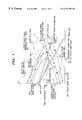
The outline of the method according to the first invention is shown with reference to FIG. 1 or FIG. 2. FIG. 1 and FIG. 2 show a CIELAB color space in a two-dimensional manner by an L* axis as a lightness axis and C* axis as a chroma axis for the sake of convenience.
In FIG. 1 and FIG. 2, a point P0 in a color gamut of a color image output apparatus (hereinafter simply referred to as an output apparatus), and the point is set on a gray axis, that is, on the L* axis in the CIELAB color space as described later. The fixed point means hereinafter the fixed point P0 in the color gamut of the output apparatus.
A point P1 is a conversion target point represented by a color coordinate value of an input image or a partial region thereof. A line L1 is a line extending from the fixed point P0 to the conversion target point P1 and is defined as a base line.
A surface (curved surface) C2 is an output color gamut surface itself of an output apparatus or a closed curved surface inside the color gamut of the output apparatus to be set as will be described later and is defined as an output color gamut surface. A surface C3 is an color gamut surface of the input image or a partial region thereof and is defined as an input color gamut surface. FIG. 1 and FIG. 2 show a case in which the input color gamut surface C3 is at the outside of the output color gamut surface C2 and the conversion target point P1 is converted by compression. On the contrary, the method of the present invention is also applicable to a case in which the output color gamut surface C2 is at the outside of the input color gamut surface C3 and the conversion target point P1 is converted by expansion.
A point P2 is an intersection between the base line L1 and the output color gamut surface C2 and is defined as an output color gamut point.
A point P3 is an intersection between the base line L1 and the input color gamut surface C3 and is defined as an input color gamut point.
A point P4 is a first conversion point which is determined by weighted mean of the fixed point P0 and the output color gamut point P2 using a first weighing coefficient. Accordingly, the first conversion point P4 is a point on the base line L1.
A point P5 is a second conversion point which is determined by using correction data for correcting the compressing direction or the expanding direction using the first weighing coefficient.
A line L5 is a line extending from the fixed point P0 to a second conversion point P5 and is defined as a correction line.
In FIG. 1 and FIG. 2, the correction line L5 is different from the base line L1 but, if the correction data is zero, the correction line L5 agrees with the base line 11. The correction data is set and prepared as discrete data in the color space as shown, for example, in FIG. 1 and FIG. 2 as correction data D1.
A point P6 is a final conversion point for the conversion target point P1 and is determined by weighted means of the first conversion point P4 and the second conversion point P5 by using a second weighing coefficient. Accordingly, the final conversion point P6 is a point on a segment connecting the first conversion point P4 with the second conversion point P5.
The outline of the method according to the third invention is shown with reference FIG. 18 and FIG. 19. FIG. 18 shows a CIELAB color space in a two-dimensional manner by using L* axis as a lightness axis and C* axis as a chroma axis, and FIG. 19 shows a CIELAB color space in a two-dimensional manner by using a* axis and b* axis.
As has been described above with respect to the first invention, also in FIG. 18 and FIG. 19, a point P0, a point P1, a curved surface C2 and a curved surface C3 are, respectively, a fixed point, a conversion target point, an output color gamut surface and an input color gamut surface.
A point P21 is a point calculated by applying correction data corresponding to the conversion target point P1 relative to the conversion target point P1 and is defined as a correction point. The correction data is provided as discrete vector data in the color space, and correction data corresponding to a necessary point can be calculated, for example, by interpolation.
A line L2 is a line connecting the correction point P21 with the fixed point P0 and is defined as a correction base line.
A curve L3 is a curve passing the conversion target point P1 and the fixed point P0 and is defined as an assumed conversion line. The correction data described above is calculated based on the assumed conversion line. The assumed conversion line is determined depending on the purpose and an iso-hue line passing the conversion target point P1 and the fixed point P0 is the assumed conversion line in a case, for example, of intending to correct bending of the hue line.
A point P22 is an intersection between a correction base line L2 and the input color gamut surface C3 and is defined as an input color gamut point.
A point P23 is an intersection between the correction base line and the output color gamut surface C2 and is defined as an output color gamut point.
A point P24 is a point obtained by compression or expansion corresponding to the color gamut of the output apparatus to the correction point P21 along the correction base line L2 and is defined as a conversion point. The compression or expansion processing corresponding to the color gamut of the output apparatus may be conducted by using the first weighing coefficient decided based on the fixed point P0, the input color gamut point P22, the output color gamut point P23 and the correction point P21, or may be conducted by an existing method.
A point P25 is a final conversion point for the conversion target point P1 and is calculated by applying inverse correction data corresponding to the conversion point P24. The inverse correction data is formed by replacing a start point and an end point of a vector of the correction data to each other.
Other points, surfaces and curves shown in FIG. 1, FIG. 2, FIG. 18 and FIG. 19 will be described later. The second invention will also be described later.
[Setting for the Fixed Point]
The fixed point P0 is set as a point fixed on a gray axis in a color gamut of the output apparatus, as a point changing continuously as a function of lightness, chroma and the like of the conversion target point P1 or as a point changing discretely in accordance with lightness, chroma and the like of the conversion target point P1.
FIG. 3 shows an example of the fixed point P0 that changes continuously as a function of lightness, chroma and the like of the conversion target point P1. This shows a relation between an angle Φ and an L* value of the fixed point P0, assuming an angle made by a vector extending from the conversion target point P1 to the fixed point P0 relative to an a*b* plane as Φ. When the fixed point P0 is defined as described above, the relation between the fixed point P0 and the conversion target point P1 is, for example, as shown in FIG. 4.
When the fixed point is set as a point changing continuously as a function of the lightness, chroma and the like of the conversion target point P1 or as a point changing discretely in accordance with the lightness, chroma and the like of the conversion target point P1 as described above, it is necessary that the base line L1 extending from the fixed point P0 to the conversion target point P1 does not intersect for the entire region in the color space as shown in FIG. 4. If the condition is not satisfied, a gradation may possibly be inverted upon compression or expansion.
When the fixed point P0 is set as a function only of the lightness of the conversion target point P1, the gradation is not inverted if the angle Φ is 0°. However, if angle Φ is other than the 0°, the gradation tends to be inverted at a high possibility and, if the lightness of the conversion target point P1 is out of the color gamut of the output apparatus, it is difficult to set the fixed point P0 in the color gamut of the output apparatus. The fixed point P0 is set while taking them into consideration.
[Output Color Gamut Surface]
The output color gamut surface C2 may usually be an color gamut surface for the color gamut of the output device. However, in a case where an output apparatus is a display or the like and white points of the input image are different from the white points of the output apparatus, it may sometimes be desirable that a closed curved surface inside the color gamut of the output apparatus is the output color gamut surface C2.
FIG. 5 schematically shows an example of a relation between a color gamut of an input image or a partial region thereof and a color gamut of an output apparatus, in which a curved surface C20 is a color gamut surface itself of an output apparatus, a surface C3 is an input color gamut surface, that is, a color gamut surface of an input image or a partial region thereof.
In this example, when a white point P1 w of an input image or a partial region thereof is converted to a compressed point P6 w on a gray axis in the color gamut of the output apparatus, since a region of higher lightness than the white point compressed point P6 w is present in the color gamut of the output apparatus, another color of the input image or the partial region thereof may sometimes be converted into a color P6 o at higher lightness than that of the white point compressed point P6 w depending on the compression method, to give an unnatural impression.
In such a case, a surface containing only the region of lower lightness than the white point compressed point P6 w as a closed curved surface in the color gamut of the output apparatus may be set and used as the output color gamut surface C2. For example, in FIG. 5, a closed curved surface C21 extended horizontally starting from the white point compressed point P6 w such that the lightness is equal to that of the white point compressed point P6 w, or a closed curved surface C22 that gradually lowers the lightness as the chroma increases starting from the white point compressed point P6 w is set as the closed curved surface in the color gamut of the output apparatus and used as an output color gamut surface C2.
As the chroma increases, a color feels visually brighter than gray at identical lightness but unnatural impression caused by such a visual phenomenon can be prevented by using the closed curved surface C22 of the latter as the output color gamut surface C2.
As a countermeasure for such a disadvantage in view of the visual sense, it may also be considered to conduct color gamut conversion after uniformly converting only the lightness at first for all the colors of the input image or the partial region thereof. However, when a color gamut expansion is conducted in addition to the color gamut compression, a similar disadvantage is also caused upon expansion, so that it is desirable to set the curved surface as the closed curved surface C22 as the output color gamut surface C2.
[First Embodiment as the Image Processing Method]
FIG. 6 shows a preferred embodiment of the first invention of determining a point in an input image or a partial region thereof, namely, a color coordination value for one pixel as the conversion target point P1 and converting the same into the final conversion point P6 of a color coordinate value adaptable to the color gamut of the output apparatus.
The method shown in FIG. 6 can be attained in a computer by means of a processing program but a portion of the steps can be executed also by hardware. This method comprises, as a whole, an output color gamut point calculation step 10, an input color gamut point calculation step 20, a first weighing coefficient deciding step 30, a second weighing coefficient deciding step 40, a first conversion point calculation step 50, a second conversion point calculation step 60 and a final conversion point calculation step 70. At first, the output color gamut point calculation step 10 or the input color gamut calculation step 20, for example, the output color gamut calculation step 10 is conducted.
(Output Color Gamut Point Calculation Step)
In the output color gamut point calculation step 10, information S2 for the output color gamut point P2 as an intersection between the base line L1, namely, a line extending from the fixed point P0 to the conversion target point P1 and the output color gamut surface C2 is calculated based on the information (color coordinate value) S1 for the conversion target point P1, information (color coordinate value) S0 for the fixed point P0, information SC2 for the output color gamut surface C2 and an output profile point calculation parameter PP2.
FIG. 7 shows a concrete example of the output color gamut point calculation step 10. In this example, information (color coordinate value) S12 for a plurality of output color gamut representative points C12 as shown in FIG. 1 and FIG. 2 is calculated based on the output color gamut surface information SC2 in the output color gamut representative point preparing step 11.
The output color gamut surface information SC2 is for the discrete data on the relation between the input signal and the output color depending on the output apparatus, as well as the shape of the output color gamut surface C2 if this is a closed curved surface in the color gamut of the output apparatus.
As the discrete data pair, data set for various YMC(K)% and LAB data may be provided, for example, when the output apparatus is a printer, or data set for various RGB and LAB data or XYZ may be provided when the output apparatus is a display.
Based on the data described above, a value to be predicted is set corresponding to a point on the color gamut surface of the output apparatus, and a color is predicted.
Setting of the value to be predicted to the point on the color gamut surface of the output apparatus corresponds to the provision of data comprising a combination of M% and C% when Y% is zero, a combination of C% and Y% when M% is zero and a combination of Y% and M% when C% is zero when the output apparatus is, for example, a three color printer.
Further, when the output color gamut surface C2 is a closed curved surface of the output apparatus, the color data on the color gamut surface in of the output apparatus is modified by using information regarding the shape thereof to form an output color gamut representative point information S12.
As the prediction method, it is possible to use a method of predicting any color outputted from an input signal of any input signal depending on the output apparatus information based on the discrete data pair regarding the relation between the input signal and the output color depending on the output apparatus. A known method can be utilized. Further, accurate predicting can be conducted by using a method proposed in Japanese Patent Application No. Hei 9-4949 (filed on Jan. 14, 1996).
The method of Japanese Patent Application No. Hei 9-4949 (hereinafter referred to as prior application) comprises linking a relation between an input signal and an output signal by means of a linear matrix equation including constant terms, and determining the weighing coefficient, the coefficient of the matrix equation and the predicted value successively by an approximate method so as to minimize the sum of squares for the output prediction value determined from a plurality of real input signal data items by using the matrix equation and the weighed Euclid distance of a plurality of real output signal data corresponding thereto.
In the output color gamut point calculation step 10 shown in FIG. 7, the conversion target point information S1 and the output color gamut representative point information S12 are converted into the polar coordinate with the fixed point P0 as the center, respectively, based on the fixed point information S0 in the polar coordinate conversion step 12 to obtain a conversion target point polar coordinate information S1 r and an output color gamut representative point polar coordinate information S12 r.
Then, in the output profile point calculation final step 13, information (color coordinate value) S2 for the output color gamut point P2 is calculated based on the conversion target point polar coordinate information S1 r, the output color gamut representative point polar coordinate information S12 r and the output color gamut point calculation parameter PP2.
Assuming the conversion target point polar coordinate as O (ro, θo, φo), and the output color gamut representative point polar coordinate as GOUTi (ri, θi, φi), in which i=1, Nout, calculation for an intersection between the base line L1 and the output color gamut surface C2 corresponds to predicting of the prediction value (ro) as a value to be predicted (θo, φo) based on N units of the data pair of (θi φi) and ri. Accordingly, calculation can be conducted by using the known method or the method of the prior application.
Since this is the polar coordinate, the output color gamut calculation parameter PP2 may be determined in accordance with the number of the output color gamut representative points P12 while taking care of the continuity for θ, φ, for example, continuity between 0° and 360° of θ.
(Input Color Gamut Point Calculation Step)
In the entire step shown in FIG. 6, information S3 for the input color gamut point P3 as an intersection between the base line L1 and the input color gamut surface C3 is calculated in the input color gamut point calculation step 20, based on the conversion target point information S1, the fixed point information S0, the pixel value information S20 for the input image or the partial region thereof, and the parameter PP3 for input color gamut point calculation.
Individual pixel values per se of the input image or the partial region thereof may be used as the pixel value information S20 of the input image or the partial region thereof. Alternatively, when the color gamut of the input image or the partial region thereof is previously assumed, for example, as an NTSCRGB color gamut, an SRGB color gamut or a color gamut represented by YMCBRGWK color coordinate points, discrete color coordinate information located at the color gamut portion of the assumed color gamut may be used.
In a case of using discrete color coordinate information located at the color gamut portion of the previously assumed color gamut, the input color gamut representative point candidate selection step and the input color gamut representative point selection step shown below can be saved.
FIG. 8 and FIG. 9 show, respectively, concrete examples of the input color gamut provided point calculation step 20. FIG. 8 is an example of selecting the input color gamut representative points from all pixel values of the input image or the partial region thereof and FIG. 9 is an example of determining the input color gamut representative candidates, for example, by thinning pixels of the input image or the partial region thereof and selecting the input color gamut representative point from the input color gamut representative point candidates.
In the example shown in FIG. 8, pixel value information S20 of the input image or the partial region thereof is at first converted into the polar coordination with the fixed point P0 as the center based on the fixed point information S0 in the polar coordinate conversion step 22 to obtain pixel value polar coordinate information S20 r. In this case, the conversion target point information S1 is also converted into the polar coordinate with the fixed point P0 as the center based on the fixed point information S0, to obtain a conversion target point polar coordinate information S1 r. Since this has already been calculated in the polar coordinate conversion step 12 in the output color gamut point calculation step 10 shown in FIG. 7, this result may be utilized.
Then, information S13 for the input color gamut representative points P13 as the discrete points in the color gamut surface C3 as shown in FIG. 1 and FIG. 2 are selected from the pixel value polar coordinate information S20 r in the input color gamut representative point selection step 23.
Specifically, assuming the pixel value polar coordinate of the input image or the partial region thereof as INi (ri, θi, φi), in which i=1, Nin, (θ, φ) plane is divided into meshes to distribute INi (ri, θi, φi), and data having maximum (r) in each of the meshes is sought and it is defined as an input color gamut representative point GINi (ri, θi, φi), in which i=1, Nin.
Then, in the input outmost profile calculation final step 24, information (color coordinate value) S3 for the input color gamut point P3 as an intersection between the base line L1 and the input color gamut surface C3 is calculated based on the conversion target point polar coordinate information S1 r, the input color gamut representative point information S13 and the input color gamut point calculation parameter PP3.
Since the conversion target point polar coordinate is O (ro, θo, φo) and the input color gamut representative point P13 is GINi (ri, θi, φi), in which i=1, Nin, calculation for the intersection between the base line L1 and the input color gamut surface C3 corresponds to the predicting of the rediction value (ro) assuming the value to be predicted as (θo, φo) based on N units of the data pair of (θi, φi) and ri. Accordingly, it can be calculated by using the known method or the method of the prior application described above.
In this case, since this is the polar coordinate, the input color gamut point calculation parameter PP3 may be determined in accordance with the number of the input color gamut representative points P13 while taking care of the continuity between 0° and 360° for 74 , φ. However, since the input color gamut surface C3 as the color gamut surface for the color gamut of the input image or the partial region thereof may sometimes has remarkable unevenness compared with the case of calculating the output color gamut information S2, it is important in this case to set the parameter PP3 for the input color gamut point calculation so as to strengthen the smoothing effect.
In the example shown in FIG. 9, the information S21 for the input color gamut representative point candidates is obtained at first in the input color gamut representative point candidate selection step 21 from the pixel value information 20 of the input image or the partial region thereof.
When the input color gamut representative point is selected from the pixel value information S20 per se of the input image or the partial region thereof as in the example shown in FIG. 8, it takes much time for the processing in the polar coordinate conversion step 22 and the input color gamut representative point selection step 23. However, when the input color gamut representative point candidate is previously selected at the input color gamut representative point candidate selection step 21 as in the example shown in FIG. 9, the processing time in the subsequent polar coordinate conversion step 22 and the input color gamut representative point selection step 23 can be shortened. For selecting the input color gamut representative point candidate, a method, for example, of merely thinning pixels of the input image or the partial region thereof or determining a mean value for several pixels and determining the mean value as the input color gamut representative point candidate information S21 can be used.
Subsequently, in the same manner as in the example shown in FIG. 8, by way of the polar coordinate conversion step 22, the input color gamut representative point selection step 23 and the final input color gamut point calculation step 24, information S3 for the input color gamut point P3 as an intersection between the base line L1 and the input color gamut surface C3 is obtained.
(First Weighing Coefficient Deciding Step)
In the entire step shown in FIG. 6, information SW1 for a first weighing coefficient used in the subsequent first conversion point calculation step 50 and the second conversion step calculation step 60 is calculated next in the first weighing efficient deciding step 30 based on the conversion target point information S1, the fixed point information S0, the output color gamut point information S2, the input color gamut point information S3 and the first weighing coefficient deciding parameter PW1.
In the first weighing coefficient deciding step 30, the first weighing coefficient is decided by conducting 1-variable function calculation of inputting a ratio between a distance from the fixed point to the conversion target point and a distance from the fixed point to the input color gamut point and outputting the first weighing coefficient. The shape of the 1-variable function will be explained with reference to FIG. 10 and FIG. 11.
FIG. 10 shows a shape of a 1-variable function in a case where a ratio R2 between the distance from the fixed point to the output color gamut point and the distance from the fixed point to the input color gamut point is 1 or less, namely, when compression is conducted as shown in FIG. 1 and FIG. 2. The shape is determined based on at least two parameters comprising a first parameter that is a first weighing coefficient W1 when the ratio R2 between the distance from the fixed point to the output color gamut point and the distance from the fixed point to the input color gamut point is an input (ratio between the distance from the fixed point to the conversion target point and a distance from the fixed point to the input color gamut point) R1, and a second parameter for deciding to set the largest proportion for the distance from the fixed point to the output color gamut point in which the coordinate is identical for the conversion target point and the first conversion point.
When the Y coordinate value for the point Pa in FIG. 10 corresponds to the first parameter and the point Pa is located on a function shape boundary L11 for linear compression/linear expansion, that is, when it is aligned with the point Pb, linear compression is conducted. When the point Pa is located on a function shape limit L12 for fidelity reproduction/clipping, namely, when it is aligned with the point Pc, the conversion target point and the first conversion point become located on the same point within the output color gamut surface C2, and is appended at the outside of the output color gamut surface C2. If Pa is located between them, conversion intermediate thereof is conducted.
The Y coordinate value for a point Pd corresponds to the second parameter, and a first weighing function shape L13 of polygonal line connecting an original point, point Pd, point Pa and point (1.0, 1.0) is formed.
In addition to the two parameters, another shape parameter may be set to form the first weighing function shape of polygonal line more specifically than the shape L13.
Then, smoothing processing is applied to the first weighing function shape L13 of polygonal line to determine a first weighing function shape L14 of curve and, finally, an actual value R11 for the ratio R1 between the distance from the fixed point to the conversion target point and the distance from the fixed point to the input color gamut point is inputted, and the Y coordinate value W1 o at an intersection Pe with the first weighing function L14 of curve is outputted as a first weighing coefficient W1 as the final output.
As the actual processing, since it is possible to predict the output value when the ratio R1 between the distance from the constant point to the conversion target point and the distance from the fixed point to the input color gamut point is inputted by inputting the first parameter and the second parameter and setting a plurality of discrete points on the first weighing function shape L13 of polygonal line by the method, for example, of the invention of the prior application by using the smoothing parameter based on the data pair for the X-coordinate value and the Y-coordinate value for the points, it is not necessary to determine the first weighing function shape L14 of curve but the first weighing coefficient W1 can be determined directly from a plurality of discrete points on the first weighing function shape L13 of polygonal line.
FIG. 11 shows the shape of a 1-variable function when the ratio R2 between a distance from the fixed point to the output color gamut point and a distance from the fixed point to the input color gamut point is greater than 1, namely, when expansion is conducted. The shape is determined by at least two parameters comprising a third parameter as a first weighing coefficient W1 when the input R1 is 1 and a second parameter for deciding whether to set an upper limit proportion for the distance from the constant point to the output color gamut point in which the coordinate is identical for the conversion target point and the first conversion point.
The Y coordinate value for the point Pa in FIG. 11 corresponds to the third parameter. When the point Pa is located on the function shape limit L11 for linear compression/linear expansion, namely, if it is aligned with Pd, linear expansion is conducted, when the point Pa is located on the function shape L12 for fidelity reproduction/clipping, namely, when it is aligned with the point Pc, the conversion target point and the first conversion point become located on one identical point and, when Pa is located between them, conversion intermediate thereof is conducted.
The Y coordinate value for a point Pd in FIG. 11 corresponds to the second parameter and a first weighing function shape L13 of polygonal line connection the original point, the point Pd and, the point Pa is formed.
In addition to the two parameters, another shape parameter may be set to form the first weighing function shape of polygonal line more specifically than the shape L13.
Then, smoothing processing is applied to the first weighing function shape L13 of polygonal line to determine a first weighing function shape L14 of curve and, finally, an actual value R1 i for a ratio R1 between a distance from the fixed point to the conversion target point and a distance from the fixed point to the input color gamut point is inputted and the Y coordinate value W1 o for an intersection Pe on the first weighing function shape L14 of curve is outputted as the first weighing coefficient W1 as the final output.
As the actual processing, since it is possible to predict the output value when the ratio R1 between the distance from the constant point to the conversion target point and the distance from the fixed point to the input color gamut point is inputted by inputting the second parameter and the third parameter and setting a plurality of discrete points on the first weighing function shape L13 of polygonal line by the method, for example, of the invention of the prior application by using the smoothing parameter based on the data pair for the X-coordinate value and the Y-coordinate value for the points, it is not necessary to determine the first weighing function shape L14 of curve but the first weighing coefficient W1 can be determined directly from a plurality of discrete points on the first weighing function shape L13 of polygonal line.
As described above, since the method shown in FIG. 10 and FIG. 11 uses a technique similar in compression and expansion, if a restriction is provided such as making the second parameter identical, it can give an advantage of being capable of conducting compression and expansion even if a certain portion is compressed and a certain portion is extended in the color space region, without deteriorating the continuity therebetween.
(Second Weighing Coefficient Deciding Step)
In the entire step shown in FIG. 6, information SW2 for a second weighing coefficient used in the subsequent final conversion point calculation step 70 is then calculated in the second weighing coefficient deciding step 40 based on the conversion target point information S1, the fixed point information S0, the input color gamut point information S3 and the second weighing coefficient deciding parameter PW2.
In this second weighing coefficient deciding step 40, the second weighing coefficient is decided by conducting 1-variable function calculation of inputting a ratio between a distance from the fixed point to the conversion target point and a distance from the fixed point to the input color gamut point and outputting the second weighing coefficient. The shape of the 1-variable function is to be explained with reference to FIG. 12.
FIG. 12 shows a shape of a 1-variable function for the second weighing coefficient W2 and the shape is decided by at least two parameters comprising a fourth parameter for deciding whether to set an upper limit of the proportion for the distance from the fixed point to the output color gamut point in which the coordinate is identical for the first conversion point and the final conversion point and a fifth parameter for deciding whether to set a lower limit of a proportion for a distance from the fixed point to the input color gamut point in which the coordinates for the second conversion point and the final conversion point are identical.
The X coordinate value for the point Pf in FIG. 12 corresponds to the fourth parameter, and the X-coordinate value for the point Pg corresponds to the fifth parameter by which a second weighing function shape L15 of a polygonal line connecting the original point, the point Pf, the point Pg and the point (1.0, 1.0) is formed.
Another shape parameter may be set in addition to the two parameters and the second weighing function shape of polygonal line may be formed more specifically than the shape L15.
Then, smoothing processing is applied to the second weighing function shape L15 of polygonal line to determine the second weighing function shape 116 of curve and, finally, an actual value R1 i for the ratio R1 between a distance from the fixed point to the conversion target point and a distance from the fixed point to the input color gamut point is inputted and the Y coordinate value W2 o at an intersection Ph on the second weighing function shape L16 of curve is outputted as the second weighing coefficient W2 for the final output.
As the actual processing, since it is possible to predict the output value when the ratio R1 between the distance from the fixed point to the conversion target point and the distance from the fixed point to the input color gamut point is inputted by inputting the fourth parameter and the fifth parameter and setting a plurality of discrete points on the second weighing function shape L15 of polygonal line by the method, for example, of the invention of the prior application by using the smoothing parameter based on the data pair for the X-coordinate value and the Y-coordinate value for the points, is not necessary to determine the second weighing function shape L16 of curve but the second weighing coefficient W2 can be determined directly from a plurality of discrete points on the second weighing function shape L15 of polygonal line.
(First Conversion Point Calculation Step)
In the entire step shown in FIG. 6, information S4 for the first conversion point P4 is calculated next in the first conversion point calculation step 50 by conducting weighted means of the first weighing coefficient, for the fixed point P0 and the output profile point P2 based on the fixed point information 80, the output color gamut point information S2 and the first weight coefficient information SW1 by using first weight coefficient.
In this case, since the first weighing coefficient is W1 and the output color gamut point information S2 is represented as GOUTo (ro, θo, φo) by the polar coordinate using the fixed point P0 as the center, calculation of the first conversion point information S4 corresponds to the determination of GOUTo (ro×W1, θo, φo) and, when it is reconverted to the orthogonal coordinate by using the coordinate value for the fixed point P0, first conversion information S4 can be obtained.
(Second Conversion Point Calculation Step)
In the entire step shown in FIG. 6, information S5 for the second conversion point P5 is calculated next in the second conversion point calculation step 60 based on the conversion target point information S1, the fixed information S0, the output color gamut surface information SC2, the correction data D1, the first weighing coefficient information SW1, and the output color gamut point calculation parameter PP2.
Calculation for the second conversion point P5 in the second conversion calculation step 60 enables continuous control for the direction of the color gamut compression or the color gamut expansion in each of the regions and corrects the bending of hue lines in the color space in view of the visual sense, to cope with a problem regarding the shape of the color gamut of the output apparatus, for example, a problem that the chroma of yellow is lowered extremely when compression is conducted at the same hue in the case of a printer.
FIG. 13 shows a concrete example of the second conversion point calculation step 60 in which the second conversion point P5 is determined as a point on the assumed output color gamut surface C1 diminished from the output color gamut surface C2 as shown in FIG. 1 or on the assumed output color gamut surface enlarged from the output color gamut surface C2 contrary to the case of FIG. 1.
As described later, when the color coordinate values for the final conversion points regarding a plurality of conversion target points obtained by the image processing method according to the present invention are accommodated as the lattice point date for color gamut conversion in a multi-conversion table, the actual entire color gamut of the output apparatus can be utilized effectively and excessively unnecessary color gamut compression can be avoided by assuming the curved surface enlarged from the color gamut surface of the actual color gamut of the output apparatus as the color gamut surface of the color gamut of the assumed output apparatus.
In the example shown in FIG. 13, correction data D1 is provided at first in the correction data preparing step 61 based on the output color gamut surface information SC2 and the input color space visual sense iso-hue information S60.
The correction data D1 is for the calculation of the second conversion point P5 and, as shown in FIG. 1, correction vector data relative to the discrete color coordinate points over the entire input color space, and it can be determined by adding the correction vector data determined from the output color gamut surface information SC2 and the correction vector data determined from the input color space visual sense iso-hue information S60.
The correction vector data is determined from the input color space visual sense iso-hue information 60 by a method, for example, of setting a plurality of chroma grades to discrete color coordinate points on the base line L1, previously determining the degree of movement only for the hue that gives an appearance of an identical hue by a visual color matching experiment, determining an assumed correction point extending from the fixed point P0 to the iso-hue point by using a ratio between a distance from the fixed point P0 to the target point P1 and a distance from the fixed point P0 to the iso-hue point for the output color gamut surface C2, determining the vector from the conversion target point P1 to the assumed correction point as a correction vector and storing the same together with information showing the proportion (percentage) of the chroma set on the line from the fixed point P0 to the iso-hue point relative to distance from the constant point P0 to the output color gamut surface C2.
The correction vector can be determined from the output color gamut surface information SC2 by a method of using the correction vector data determined from the input color space visual color iso-hue information S60, then preparing various kinds of compression samples under the conditions that the value obtained by weighted addition for the hue difference, lightness difference and the chroma difference before and after the compression is minimized, determining the optimal value for the weighing ratio by a functional test for each of the regions and determining the correction vector data for the color on the base line L1 by inverse calculation from the ratio of the optimal value. The situation is the same also for the expansion.
Further, as a method of determining both of the correction vector data all at once, it is possible to determine the optimal conversion destination on the assumed output color gamut surface C1 by a functional test with respect to the discrete color coordinate points over the entire region of the input color space and inversely calculating the correction vector data based on the color coordinate.
It is possible to consider a method of directly using a vector from the conversion target point P1 to the second conversion point P5 on the assumed output color gamut surface C1 as the correction data D1. However, since it is difficult to conduct calculation such that the second conversion point P5 is always located on the assumed output color gamut surface C1 in view of the predicting accuracy in the next correction value calculation step 62, it is desirable for the correction data to be unlikely to be affected by the shape of the output color gamut surface C2 as in this example.
In the example shown in FIG. 13, information S61 for the correction value relative to the conversion target point P1 is calculated next in the corrected value calculation step 62 based on the correction data D1 and the conversion target point information S1.
Assuming the first weighing coefficient as p, the conversion target point P1 as GINo (Lo, ao, bo, p), the original point and the correction data D1 for calculating the second conversion point P5 as GCoe (Loi, aoi, boi, pe) and GCce (Lci, aci, bci, pe), in which i=1, Nc, in this case calculation of the correction value information S61 corresponds to the predicting of the prediction value GCoc (Loc, aoc, boc) with GINo (Lo, ao, bo, p) being the value to be predicted based on N units of the data pairs of Gcos (Loc, aoi, boi, pe) and Gcce (Lci, aci, bci, pe).
Accordingly, the information can be calculated by using the known method or the method of the prior application.
Then, in the correction point calculation step 63, the information S7 for the conversion target correction point P7 as shown in FIG. 1 that is the point after amendment of the conversion target point is calculated next in the correction point calculation step 63 based on the correction value information S61 and the conversion target S1. Specifically, the conversion target correction point GCc (Lc, ac, bc) can be determined by merely adding the correction value GCoc (Loc, aoc, boc) to the conversion target point GINo (Lo, ao, bo).
Then, in the second conversion point calculation final point 65, information S5 for the second conversion point P5 as an intersection between the correction like L5 as a line extending from the fixed point P0 to the conversion target correction point P7 and the assumed output color gamut surface C1 is calculated based on the conversion target correction point information S7, the fixed point information S0, the output color gamut representative point polar coordinate information S12 r obtained in the polar coordinate conversion step 12 in FIG. 7, the first weighing coefficient information SW1 and the parameter PP2 for calculating the output color gamut point as shown in FIG. 1.
Assuming the conversion target correction point GCc (Lc, ac, bc) converted into the polar coordinate with the fixed point P0 as the center as Gcc (rc, θc, φc), since the output color gamut representative point polar coordinate is GOUTi (ri, θi, φi), in which i=1, Nout, calculation of the second conversion point P5 as the intersection between the correction line L5 and the assumed output color gamut surface C1 corresponds to the predicting of the prediction value (rc) for the value to be predicted as (θc, φc) based on N units of the data pair of (θi, φi) and p×ri. Accordingly, the conversion point can be calculated by using a known method or the method of the prior application.
According to the second conversion point calculation step in the example shown in FIG. 13 described above, it is possible to correct the visual bending of the hue line in the color space accurately and to cope with a problem regarding the shape of the color gamut of the output apparatus by the second conversion point calculation step of the example in FIG. 13, and the second conversion point P5 can be calculated by a more simple and convenient method according to the example shown in FIG. 14.
In the example shown in FIG. 14, correction data D1 is prepared at first in the correction data preparation step 61 based on the output color gamut surface information SS2 and the input color space visual iso-hue information S60.
The correction data D1 in this case is for the calculation of the input color gamut correction point P8 and, further, the input color gamut optimal conversion point P9 as shown in FIG. 2, and is correction vector data relative to the discrete color coordinate points over the entire input color space and this can be determined by adding the correction vector data determined from the output color gamut surface information SC2 and the input color space visual iso-hue information S60.
The correction vector data may be determined from the input color space visual iso-hue information S60, for example, by using a method of determining the degree of movement only for the hue relative to the color on the base line L1 for giving the same appearance of hue as the output color gamut point P2 by a visual color matching experiment and setting a vector contrary thereto.
The correction vector data can be determined from the output color gamut surface information SC2, for example, by a method of using the correction vector data determined from the input color space visual iso-hue information 60, then, preparing various kinds of compression samples under the condition that the value obtained by weighing addition for the hue difference, the lightness difference and the chroma difference before and after the compression is minimized, determining the optimal value for the weighing ratio by a functional test for each of the regions and determining the correction vector data for the color on the base line 11 by inversely calculating from the ratio of the optimal value. The situation is the same also for the expansion.
As a method of determining both of the correction vector data all at once, it is possible to determine the optimal conversion destination on the output color gamut surface C2 by a functional test relative to the discrete color coordinate points of the input color space and inversely calculating the correction vector data from the color coordinate.
Then, in the correction value calculation step 62, information S62 for the correction value relative to the input color gamut point P3 is calculated based on the correction data D1 and the input color gamut information S3.
Assuming the input color gamut point P3 as GINo (Lo, ao, bo), and the original point and the correction data D1 as for the calculation of the input color gamut optimal conversion point P9 GCoe (Loi, aoi, boi) and GCce (Lci, aci, bci), in which i=1, Nc, calculation of the correction value information S62 corresponds to the predicting of the prediction value GCoc (Loc, aoc, boc) for the value to be predicted as GINc (Lo, ao, bo) based on N units of the data pair of GCoe (Loi, aoi, boi) and GCce (Lci, aci, bci). Accordingly, the information can be calculated by using a known method or the method of the prior application.
Then, in the correction point calculation step 63, information S8 for the input color gamut correction point P8 as shown in FIG. 2, that is, the point after the amendment for the input color gamut point P3 is calculated based on the correction value information S62 and the input color gamut point information S3. Specifically, the input color gamut correction point GCc (Lc, ac, bc) can be obtained by simply adding the correction value GCoc (Loc, aoc, boc) to the input color gamut point GINo (Lo, ao, bo).
Then, in the input color gamut optimal conversion point calculation step 64, the information S9 for the input color gamut optimal conversion point P9 as an intersection between the correction line L5 which is a line extending from the fixed point P0 to the input color gamut correction point P8 and the output color gamut surface C2, namely, the optimal conversion destination for the input color gamut point P3 as shown in FIG. 2 is calculated based on the input color gamut correction point information S8, fixed point information S0, the output color gamut representative point polar coordination information S12 r obtained in the polar ordinate conversion step 12 in FIG. 7 and the parameter PP2 for calculating the output color gamut point.
Assuming the input color gamut correction point GCc (Lc, ac, bc) converted into the polar coordinate having the fixed point P0 as the center as GCc (rc, θc, φc), since the output color gamut representative point polar coordinate is GOUTi (ri, θi, φi), in which i=1, Nout, calculation of the input color gamut optimal conversion point P9 as an intersection between the correction line L15 and the output color gamut surface C2 corresponds to the predicting of the prediction value (rc) for the value to be predicted as (θc, φc) based on N units of the data pair for (θi, φi) and ri. Accordingly, calculation can be conducted by using a known method or the method of the prior application.
Then, in the second conversion point calculation final step 65, information S5 for the second conversion point P5 on the correction line L5 is calculated as shown in FIG. 2, by weighted mean of the fixed point P0 and the input color gamut optimal conversion point P9 by using the first weighing coefficient, based on the input color gamut optimal conversion point information S9, the fixed point information S0 and the first weighing coefficient information SW1.
Then, since the first weighing coefficient is W1 and the input color gamut optimal conversion P9 expressed by the polar coordinate with the fixed point p0 as the center is GCc (rc, θc, φc), calculation for the second conversion point information S5 corresponds to the determination of GCc (rc×W1, θc, φc) and, when this is reconverted into the orthogonal coordinate by using the coordinate value for the fixed point P0, the second conversion point information S5 is obtained.
(Final conversion Point Calculation Step)
In the entire step shown in FIG. 6, information S6 for the final conversion point P6 with respect to the conversion target point P1 is calculated finally in the final conversion point calculation step 70 by weighted mean of the first conversion point P4 and the second conversion point P5 using the second weighing coefficient based on the first conversion point information S4, the second conversion point information S5 and the second weighing coefficient information SW2.
Assuming the second weighing coefficient as W2, the first conversion point P4 as OUT1 (L1, a1, b1), and the second conversion point P5 as OUT2 (L2, a2, b2), calculation for the final conversion point P6 corresponds to the determination of OUT0 (L1×(1−W2)+L2×W2, a1×(1−W2)+a2×W2, b1×(1−W2)+b2×W2).
The final conversion point P6 is determined as a point on a segment connecting the first conversion point P4 with the second conversion point P5. In FIG. 1 and FIG. 2, the final conversion point curve C6 is a trace drawn from the fixed point P0 to the final conversion point P6 when the conversion target point P1 is gradually moved in the direction of the output color gamut point P2. The curve is along with a segment from the conversion target point P1 to the output color gamut point P2 at the initial state but it gradually changes its direction to the conversion target correction point p7, the input color gamut correction point P8 or the input color gamut optimal conversion point P9.
[Second Embodiment as the Image Processing Method]
FIG. 15 shows a second embodiment of the image processing method according to the present invention. In this embodiment, a memory part 82 is disposed to a color gamut conversion processing unit 81 and the memory part 82 previously contains a correction vector for correcting the visual bending of a hue line for each of the regions of the color space, that is, for each region of the CIELAB color space in this example.
Further, the memory part 82 contains information showing the color gamut surface for the color gamut and the output color gamut surface as the closed curved surface in the color gamut of the output apparatus, and an input color gamut surface as the color gamut surface for the color gamut of an input image or a partial region thereof.
Then, the color gamut conversion processing unit 81 converts the color gamut of input image data Li, ai, bi by using the correction vector stored in the memory part 82 in accordance with the color gamut of the output apparatus and the color gamut of the input image by the output color gamut surface information and the input color gamut surface information stored in the memory part 82 and outputs image data Lo, ao, bo after the conversion.
According this procedure, optimal color gamut conversion can be conducted in accordance with the color gamut of the output apparatus and the color gamut of the input image and, particularly, visual bending of the hue line can be corrected reliably in each of the regions of the color space.
[Third Embodiment as the Image Processing Method]
FIG. 20 shows a preferred embodiment of the third invention of setting a certain point in an input image or a partial region thereof, namely, a color coordinate value for a pixel as a conversion target point P1 and converting the same into a final conversion point P25 of a color coordination value present on the assumed conversion line L3 and adaptable to the color gamut of the output apparatus.
The method comprises a correction point calculation step 110, a conversion point calculation step 120 and an inverse collection point calculation step 130.
In this embodiment, explanation is to be made for an example intended to conduct compression in accordance with the color gamut of the output apparatus taking distortion of the CIELAB color space into consideration. Accordingly, the assumed conversion line L3 in this example is an iso-hue line.
(Correction Point Calculating Step)
The correction point calculation step 110 calculates the correction point P21 by using the conversion target point P1 and a collection data D2.
The correction D2 in this embodiment is defined as a group of three-dimensional vectors having a correction amount from a plurality of discrete points in the CIELAB color space to the direction L*, the direction a* and the direction b*.
FIG. 21 is a view explaining a correction vector V constituting the correction data D2 for correcting the distortion of the CIELAB color space. The graph is expressed in a two-dimensional manner with a* axis and b* axis of the CIELAB color space.
The start point Vs for the correction vector V is a conversion target point to which the correction vector V corresponds. The end point Ve for the correction vector V is determined depending on the correction amount for correcting the distortion of the color space in direction of each the axis.
Specifically, if an assumed conversion line L3 passing the start point Vs and the fixed point Po determined uniquely by the start point Vs, with an iso-hue and with uniformly varying lightness and chroma is present, an intersection between the assumed conversion line L3 and a closed curved surface referred to as a reference surface C4 is defined as a reference point P26. The reference surface C4 may be any of closed curved surfaces that intersects a semi-line extending from a fixed point P0 corresponding to an arbitrary point to the arbitrary point only for once. In this case, the output color gamut surface C2 is used as the closed curved surface C4.
The reference point P26 is a point to which the start point Vs is converted upon conversion of the start point Vs into the point on the reference surface considering the strain of the color space. Then, a point situating on the line L4 passing the reference point P26 and the fixed point P0 and has an equal chroma value with the start point Vs is defined as an end point Ve. In this way, the correction data D2 can be prepared from the assumed conversion line L3 based on the reference surface C4.
The correction point P21 is calculated by determining a correction vector corresponding to the conversion target point P1, namely, starting from the conversion target point P1 by interpolating the three-dimensional vector group of the correction data D2 prepared as explained above, and adding the correction vector to the conversion target point P1.
(Conversion Point Calculation Step)
The conversion point calculation step 120 converts the correction point P21 calculated in the correction point calculation in the correction point calculation step 110 into the point on the semi-line extending from the fixed point P0 to the correction point P21, corresponding to the color gamut of the output apparatus.
In this embodiment, the conversion point P24 was calculated based on the first weighing coefficient W1, the output color gamut point P23 and the fixed point P0 relative to the correction point P21 calculated in the input color gamut point calculation step, the output color gamut point calculation step and the first weighing coefficient deciding step as described specifically with respect to the embodiment of the first invention. However, it is necessary to read the conversion target point P1 as the correction point P21, the first conversion point P4 as the conversion point P24 and the base line L1 as the correction base line in each of the steps. Specifically, the conversion point P24 was calculated according to the formula:
P24=P0+W1×(P23−P0).
In this embodiment, while a calculation method for the conversion point adaptable to the original document was used, any of compression or expansion methods adaptable to the color gamut of the output apparatus may be used so long as the conversion point can be calculated on the correction base line in this third invention. Accordingly, the conversion point P24 may always be determined as the output color gamut point P23 or an existing method may be used.
Further, if the difference between the correction base line L2 and the assumed conversion line L3 in the color gamut of the output apparatus is small enough, the conversion point calculated may be used as the final conversion point. In this case, the succeeding inverse correction point calculation step can be saved.
(Inversion Correction Point Calculation Step)
The inversion correction point calculation step 130 calculates the final conversion point with respect to the conversion point P24 calculated in the conversion point calculation step 120 by applying an inverse correction data D3 corresponding to the conversion point P24.
The inverse correction data D3 in this embodiment is defined as a group of three-dimensional vectors having the amount of correction from a plurality of discrete points dispersed in the CIELAB color space to the L* direction, a* direction and b* direction.
The inversion correction vector constituting the inversion correction data D3 is equal with the correction vector contained in the correction data D2 with the start point and the end point being replaced with each other. That is, if a correction vector V corresponding to the conversion target point Vs to be contained in the correction data D2 is present, the inverse correction vector V′=−V corresponding to the conversion point Ve can be added as the inversion correction data D3. Accordingly, D2 and D3 as different data can be maintained, or the correction data D2 can be replaced with the inverse correction data D3.
In this way, an inverse correction vector V′ corresponds to the conversion point P24 is calculated from the correction data D2 or the inverse correction data D3 by interpolation or prediction. Then, the final conversion point P25 is calculated by adding the inverse correction vector V′ to the conversion point P24.
In this embodiment, the final conversion point P25 is described as an appropriate conversion point for the conversion target point P1, but the final conversion point P25 may be determined as the second conversion point explained in the first embodiment and the final conversion point can be calculated from the second conversion point and the corresponding first conversion point.
In accordance with the method described above, the conversion target point P1 on the assumed conversion line L3 can also be converted accurately into the final conversion point P25 on the assumed conversion line L3. In this embodiment, since the assumed conversion line is determined as the iso-hue line, the final conversion point P25 can be calculated while preserving the hue of the conversion target point P1 as it is.
While the assumed conversion line has been explained to be assumed as the iso-hue line, the present invention is not restricted only thereto and, for example, an assumed conversion line for approaching to a more preferred color such as a memory color or a assumed conversion line prepared by the synthesis thereof may be used.
(Preferred Embodiment as Coefficient Generating and Imaging Processing Device)
In the image processing method described previously with reference to FIG. 1 to FIG. 14 and FIG. 18 to FIG. 21, pixel values for the final conversion points were determined one by one for the individual pixel value of the input image or the partial region thereof as the conversion target points and the entire input image or the partial region thereof may be converted for the color gamut but this processing is time consuming and not practical.
Then, in the present invention, a coefficient for the color gamut conversion is further generated by using the image processing method described previously and the coefficient thus generated is placed in the image processing apparatus so that the color gamut for the input image or the partial region thereof can be converted at a high speed and conveniently.
FIRST EXAMPLE
FIG. 16 shows an example of an image processing apparatus according to the present invention. This example shows a case of conversing the color gamut of the input image and outputting the same to a color printer 93 by a three-dimensional table interpolation calculation unit 91 comprising a three-dimensional table and an interpolating calculation unit and four one-dimensional tables 92 y, 92 m, 92 c and 98 k.
All the lattice point data contained in the three-dimensional table is formed as the final conversion points described above by determining the input values corresponding to the respective lattice point as the conversion target point and converted into the color space depending on the output apparatus, namely, a color printer in this example.
For converting into the color space depending on the output apparatus, since the three-dimensional space at the input is converted into the four-dimensional space at the output, the degree of freedom is reduced by one grade such as determination for the method of forming a black print.
Further, since the lattice points include the point situating to the outside of the color gamut of the color gamut of the input image and not all the data obtained as the final conversion points situate within the color gamut of the output apparatus, it is necessary to use a method of high extrapolating performance. In this regard, the method of the prior application can be used.
The feature that not all the obtained final conversion data are contained in the color gamut of the output apparatus constitutes a major feature of the present invention that the data can be extrapolated also to the conversion target points out of the color gamut of the input image, whereby excessively unnecessary color gamut compression can be avoided.
Particularly, when clipping is conducted by the selection of the parameter, excessively unnecessary color gamut compression can be avoided since the data can be reproduced at a high fidelity in the color gamut of the actual output apparatus by using the method of the present invention for the generation of the lattice point data by assuming the surface just outside of the color gamut of the output apparatus, for example, a range of the color gamut where YMCK% corresponds to −10% to 110%, as the color gamut of the assumed output apparatus, while taking advantage of the extrapolation.
When the data obtained as the final conversion points by the methods described above is contained in the three-dimensional table of the three-dimensional table interpolating calculation unit 91 as the lattice point data, the input/output relation for the one-dimensional tables 92 y, 92 m, 92 c and 92 k is set as the next step.
Since not all the final conversion points are contained in the color gamut of the output apparatus, namely, the input values of the one-dimensional table are not always within a range from 0% to 100%, it is necessary in this case to make an input range somewhat broader than the output range and the output range is always contained in the color gamut of the output apparatus.
The extent of broadening the input range varies depending on the extent of calculation error and the extent of smoothing for the input color gamut but it may be set such that the input range is set from −10% to 10%, in which the output values are set to 0% for the input values of 0% or lower and the output values are set to 100% for the input value of 100% or more and the input values and the output values are made identical between them. The actual color printer causes aging change and such aging change can be absorbed by the setting of the one-dimensional tables.
Subsequently, the system may be operated as an image processing apparatus. In this case, the three-dimensional table of the three-dimensional table interpolating calculation unit 91 is retrieved in this example by upper digit bits for the L*′a*′b*′ data, the lattice point data is read out of the three-dimensional table, the read out lattice point data is put to interpolating calculation in the interpolating calculation unit by lower bits for the input L*′a*b*′ data to output the color space data depending on the output apparatus, namely, Y′M′C′K′% in this embodiment which are substantially adaptable to the color gamut of the output apparatus from the three-dimensional table interpolating calculating unit 91.
As the interpolating method, a method of conducting interpolating calculation while dividing a unitary cubic body into six trigonal cones, a method of conducting interpolating calculation while dividing the unitary cubic body into two trigonal pillars, or applying interpolation as it is to the unitary cubic body are known and any of the methods may be used.
Y′M′C′K′%, in this embodiment, from the three-dimensional table interpolating calculation unit 91 are converted finally into the color space data depending on the output apparatus to be contained finally in the color gamut of the output apparatus, namely, YMCK% in this embodiment.
Then, YMCK% is outputted to the color printer 93 and, as a result, color of print images, namely, L*′a*′b*′ are outputted in this embodiment.
In a case where the input image is regionally divided into partial regions and the content of the color processing is changed on every partial region, the partial region data after processing is written into a page memory of the color printer 93, the next partial region is processed after changing the lattice point data of the three-dimensional table interpolating calculation unit 91 and, when processing is completed for all of the partial regions, the data is finally print out.
The input color space is not restricted to CIELAB and the method is applicable also to other color space such as RGB, XYZ and YIQ. Further, it is also applicable in the same manner as the color printer, for example, to a color display excepting that the three one-dimensional tables may be used and excepting for the conditions to be noted for setting the color gamut of the output apparatus described previously.
SECOND EXAMPLE
FIG. 17 shows another example of the image processing apparatus according to the present invention. This example shows a case in which the color gamut of the input image is converted by a matrix masking unit 95 and one-dimensional tables 96 r, 96 g and 96 b and outputted to a color display 97, in which a coefficient for the calculation processing is set to the matrix masking unit 95.
For this purpose, all the lattice points in the color gamut of the input image or the partial regions thereof are assumed as the input lattice points, the final conversion points are calculated by the method described above while determining the input values corresponding thereto as the conversion target points and the calculation result converted into the color space depending on the output apparatus are determined as the output lattice point data, and the coefficient is set by the least square method from the input lattice point data and the output lattice point data.
For conversion into the color space depending on the output apparatus, since not all the data obtained as the final conversion points is contained in the color gamut of the output apparatus because of the calculation error or smoothing for the input color gamut described above, it is necessary to use a method of high extrapolating performance and, for example, the method of the prior application can be used.
Then, input/output relation is set for the one-dimensional tables 96 r, 96 g, 96 b. Since not all the final conversion points are contained within the color gamut of the output apparatus, that is, the input values for the one-dimensional tables are not always present between 0 to 255, it is necessary to make the input range somewhat broader than the output range and that the range of the output is always contained within the color gamut of the output apparatus.
The extent for broadening the input range varies depending on the degree of the calculation error and smoothing for the input color gamut, and it may be set, for example, such that the input range is set from −25 to 28%, in which the output values are set to zero for the input values of 0 or lower, the output values are set to 255 for the input values of 255 or higher, and the input value and the output values are set identical at the intermediate thereof. The actual color display causes aging change, and it is possible to absorb the aging change by the setting of the one-dimensional table.
Subsequently, the system may be operated as an image processing apparatus. In this case, the data for the input image or the partial region thereof, X′Y′Z′ data in this embodiment, is put to matrix calculation processing in a matrix masking unit 95, and color space data depending on the output apparatus substantially adaptable to the output apparatus, namely, R′G′B′ in this embodiment is outputted from the matrix masking unit 95.
The calculation methods include various methods from a basic calculation at low order such as 3×3 matrix to calculation at high order with addition of higher order term or a cross term, and the method may be selected while considering the balance between the required calculation accuracy and the calculation cost.
R′G′B′ data, in this embodiment, from the matrix masking unit 95 is finally converted by the one-dimensional tables 96 t, 96 g and 96 b into a color space data depending on the output apparatus contained in the color gamut of the output apparatus, namely, RGB data in this embodiment.
Then, the RGB data is outputted to the color display 97 and, as a result, display expression colors, namely, L*′a*′b*′ in this embodiment are outputted.
When the input image is regionally divided into partial regions and the content of the color processing is changed on every partial region, the partial region data after processing is written into a page memory of the color display 97 and, further, the succeeding partial region is processed after changing the coefficient of the matrix masking unit 95 and finally indicated on the display after completing the processing to all the partial regions.
The input color space is not restricted to XYZ but the invention is applicable also to other color spaces such as RGB, CIELAB and YIQ. Further, the invention is not restricted to the color display but applicable also to a color printer in the same manner as in the color display excepting that a function of forming a black print is added to the matrix masking unit 95, four one-dimensional tables are used and that the conditions to be noted for the setting of the color gamut of the output apparatus described above are different.
The present invention can provide the following advantageous effects.
(1) Only the range requiring color gamut compression can be compressed depending on the distribution of the input image. Accordingly, lowering of the chroma can be minimized and the color difference with the original can be reduced.
(2) The direction of the color gamut compression can be controlled continuously for each of the ranges. Accordingly, an optimal compressing direction can be selected in accordance with the bending of the hue line of the input color space and the shape of the color gamut of the output apparatus.
(3) The amount of the color gamut compression also including the clipping can be controlled continuously. Accordingly, various extents of compression or expansion can be selected by merely changing the parameter depending on the user's preference.
(4) When the color gamut is compressed by a color converter of a multi-dimensional DLUT interpolating calculation type, excessively unnecessary color gamut compression can be avoided, particularly, upon clipping. Accordingly, occurrence of color difference or pseudo contour formed in the color gamut of the output apparatus can be prevented.

Claims (46)

What is claimed is:
1. An image processing apparatus for converting a color input image or a partial region thereof in accordance with a color gamut of a color image output apparatus, comprising:
a correction point calculation part that corrects a conversion target point and calculating a correction point by using correction data corresponding to said conversion target point;
a first conversion point calculation part that compresses or expands a conversion target point to a point on a line connecting a fixed point in the color gamut of said output apparatus that can be determined uniquely based on said conversion target point with said conversion target point thereby calculating a first conversion point;
a second conversion point calculation part that compresses or expands a correction point to a point on a line connecting said fixed point with said correction point thereby calculating a second conversion point; and
a final conversion point calculation part that determines a final conversion point for said conversion target point by using said first conversion point and said second conversion point.
2. An image processing apparatus for converting a color input image or a partial region thereof in accordance with a color gamut of a color image output apparatus, comprising:
an output color gamut point calculation part that determines a color gamut point as an intersection between a base line that is a line extending from a fixed point in the color gamut of said output apparatus to a conversion target point and an output color gamut surface as a color gamut surface of the color gamut or a closed curved surface in the color gamut of said output apparatus;
an input color gamut point calculation part that determines an input color gamut point as an intersection between said base line and an input color gamut surface as the color gamut surface of the color gamut of said input image or said partial region thereof;
a first conversion point calculation part that determines a first conversion point on said base line using said fixed point, said output color gamut point and a first weighing coefficient;
a second conversion point calculation part that determines a second conversion point by using correction data for correcting a compressing direction or an expanding direction and said first weighing coefficient; and
a final conversion point calculation part that determines a final conversion point for said conversion target point by using said first conversion point, said second conversion point and a second weighing coefficient.
3. An image processing method of converting a color input image or a partial region thereof in accordance with a color gamut of a color image output apparatus, wherein said conversion processing in accordance with the color gamut of said output apparatus is conducted while correcting the direction and the extent of compression/expansion by using correction data, comprising:
a first conversion point calculation step of compressing or expanding a conversion target point to a point on a line connecting a fixed point in the color gamut of said output apparatus, that can be determined uniquely based on said conversion target point, with said conversion target point thereby calculating a first conversion point;
a second conversion point calculation step of calculating a correction point by using correction data corresponding to said conversion target point and compressing or expanding said correction point to a point on a line connecting said fixed point with said correction point thereby calculating a second conversion point; and
a final conversion point calculation step of determining a final conversion point for said conversion target point by using said first conversion point and said second conversion point.
4. The image processing method according to claim 3, further comprising an inverse correction point calculation step of correcting said first conversion point or said second conversion point calculated by compressing or expanding the correction point based on inversion correction data corresponding to said first conversion point or said second conversion point.
5. The image processing method according to claim 3, further comprising the steps of:
determining a first weighing coefficient which is a ratio of compressing or expanding said conversion target point or said correction point by using an intersection between a line connecting a fixed point in the color gamut of said output apparatus that can be determined uniquely based on said conversion target point with said conversion target point or said correction point and the input color gamut surface and the output color gamut surface; and
conducting compression or expansion along a line connecting said fixed point with said conversion target point and/or correction point based on said first weighing coefficient.
6. The image processing method according to claim 3, further comprising:
an output color gamut point calculation step of determining a color gamut point as an intersection between a base line that is a line extending from the fixed point in the color gamut of said output apparatus to the conversion target point and an output color gamut surface that is the color gamut surface of the color gamut or the closed curved surface in the color gamut of said output apparatus; and
an input color gamut point calculation step of determining an input color gamut point as an intersection between said base line and an input color gamut surface that is the color gamut surface of a color gamut of said input image or said partial region,
wherein the first conversion point is determined by the first conversion point calculation step by using said fixed point, said output color gamut point and a first weighing coefficient,
the second conversion point is determined by the second conversion point calculation step by using correction data for correcting the compressing direction or expanding direction and the first weighing coefficient, and
the final conversion point is determined by the final conversion point calculation step by using said first conversion point, said second conversion point and a second weighing coefficient.
7. An image processing method according to any one of claims 5 and 6, wherein said first weighing coefficient is determined by conducting 1-variable function calculation of inputting a ratio R1 between a distance from said fixed point to said conversion target point and a distance from said-fixed point to said input color gamut point and outputting said first weighing coefficient, and
a shape of the 1-variable function is determined, if a ratio R2 between a distance from said fixed point to said output color gamut point and a distance from said fixed point to said input color gamut point is 1 or less, by at least two parameters comprising a first parameter in which said ratio R2 is the first weighing coefficient at input R1 and a second parameter for determining whether to set a proportion for the distance from said fixed point to said output color gamut point in which the coordinate for said conversion target point and said first conversion point is identical, and if said ratio R2 is 1 or greater, by at least two parameters comprising a third parameter, which are the first weighing coefficient if said input R1 is 1, and the second parameter.
8. The image processing method according to claim 6, wherein said second conversion point calculation step comprises:
a correction data preparation step of previously calculating discrete data as said correction data based on a iso-hue information of input color space and information for said output color gamut surface;
a correction value calculation step of calculating a correction value corresponding to said conversion target point by using the correction data thus calculated;
a correction point calculation step of determining a conversion target correction point by adding the correction value thus calculated to said conversion target-point data;
an output color gamut representative point preparation step of previously calculating a plurality of representative points on said output color gamut surface;
a polar coordinate conversion step of converting a coordinate for the plurality of output color gamut representative points thus calculated into a polar coordinate with said fixed point as a center; and
a final second conversion point calculation step of determining said second conversion point as an intersection between a line extending from said fixed point to said conversion target correction point and an assumed output color gamut surface diminishing or enlarging said output color gamut surface with said first weighing coefficient based on the polar coordinate for the plurality of output color gamut representative points thus converted.
9. The image processing method according to claim 6, wherein said second conversion point calculation step comprises:
a correction data preparing step of previously calculating discrete data as said correction data based on a iso-hue information of input color space and the information for said output color gamut surface;
a correction value calculation step of calculating a correction value corresponding to said input color gamut point by using the correction data thus calculated;
a correction point calculation step of determining an input color gamut correction point by adding the correction value thus calculated to said input color gamut point data;
an output color gamut representative point preparing step of previously calculating a plurality of representative points on said output color gamut surface;
an input color gamut optimal conversion point calculation step of determining an input color gamut optimal conversion point as an intersection between a line extending from said fixed point to said input color gamut correction point and said output color gamut surface based on the plurality of output color gamut representative points thus calculated; and
a final second conversion point calculation step of determining said second conversion point by weighing mean of the input color gamut optimal conversion point thus calculated and said fixed point by using said first weighing coefficient.
10. The image processing method of claim 6, wherein said second weighing coefficient is decided by conducting 1-variable function calculation of inputting a ratio R1 between a distance from said fixed point to said conversion target point and a distance from said fixed point to said input color gamut point and outputting said second weighing coefficient, and
a shape of the 1-variable function is decided by at least two parameters comprising a fourth parameter for deciding to set an upper limit of a proportion for the distance from said fixed point to said input color gamut point in which the coordinate is identical for said first conversion point and said final conversion point, and a fifth parameter for deciding to set a lower limit of a proportion for the distance from said fixed point to said input color gamut point in which the coordinate is identical for said second conversion point and said final conversion point.
11. The image processing method of claim 6, wherein said output color gamut point calculation step comprises:
an output color gamut representative point preparation step of previously calculating a plurality of representative points on said output color gamut surface;
a polar coordinate conversion step of converting the coordinate for the plurality of output color gamut representative points thus calculated into a polar coordinate with said fixed point as a center; and
a final output color gamut point calculation step of determining said output color gamut point based on the polar coordinate information after said conversion and the polar coordinate information of said conversion target point having said fixed point as a center.
12. The image processing method of claim 6, wherein said input color gamut point calculation step comprises:
a polar coordinate conversion step of converting pixel values of said input image or said partial region thereof into a polar coordinate with said fixed point as a center;
an input color gamut representative point selection step of determining a pixel having a maximum absolute value on each local expected angle of the polar coordinate after said conversion as a plurality of representative points on said input color gamut surface; and
a final input color gamut point calculation step of determining said input color gamut point based on the representative point information thus obtained and the information for said conversion target point.
13. The image processing method of claim 6, wherein said input color gamut calculation step comprises:
an input color gamut representative point candidate selection step of selecting a plurality of input color gamut representative point candidates from pixel values of said input image or said partial region thereof;
a polar coordinate conversion step of converting pixel values for the input color gamut representative point candidates thus obtained into a polar coordinate with said fixed point as a center;
an input color gamut representative point selection step of determining pixels each having a maximum absolute value on every local expected angle of the polar coordinate after said conversion as a plurality of representative points on said input color gamut surface; and
a final input color gamut point calculation step of determining said input color gamut point based on the representative point information thus obtained and the information for said conversion target point.
14. The image processing method of claim 6, wherein said input color gamut point calculation step determines said input color gamut point based on the information for the plurality of representative points on said input color gamut surface previously stored and the information for said conversion target point when the color gamut of said input image or said partial region thereof is known or defined.
15. A method of forming lattice point data which comprises the steps of:
determining a final conversion point by the image processing method according to claim 3 using a plurality of representative points in a color gamut of a color input image or a partial region thereof as a conversion target point; and
determining color coordinate values for the plurality of final conversion points thus obtained or color coordinate values after converting the same into a color space depending on an output apparatus as lattice point data to be contained in a multi-dimensional conversion table used for converting the color gamut of a color input image or a partial region thereof.
16. A method of forming a conversion coefficient which comprises the steps of:
determining a final conversion point by an image processing method according to claim 3 using a plurality of representative points in a color gamut of a color input image or a partial region thereof as conversion target points; and
forming a coefficient for converting the color gamut of the color input image or the partial region thereof based on a corresponding relation between the conversion target points thus obtained and the final conversion points.
17. An image processing apparatus for converting a color input image or a partial region thereof in accordance with a color gamut of a color image output apparatus, comprising:
a pre-stage conversion processing unit having a multi-dimensional conversion table in which lattice point data formed by the lattice point data forming method according to claim 15 is stored, retrieving said multi-dimensional conversion table using the pixel values of said input image or said partial region as the address, and conducting interpolating calculations for the read out lattice point data using the pixel values for said input image or said partial region thereof to obtain image values of a color space substantially adaptable to the color gamut of said output apparatus and depending on said output apparatus; and
a post-stage conversion processing unit having a plurality of one-dimensional conversion tables for converting pixel values obtained from said pre-stage conversion processing unit into image values finally contained in the color gamut of said output apparatus.
18. An image processing apparatus for converting a color input image or a partial region thereof in accordance with a color gamut of a color image output apparatus, comprising:
a pre-stage conversion processing unit for conducting matrix calculations for the pixel values of said input images or said partial region thereof using the coefficient formed by the conversion coefficient forming method according to claim 16, to obtain image values of a color space substantially adaptable to the color gamut of said output apparatus and depending on said output apparatus; and
a post-stage conversion processing unit having a plurality of one-dimensional conversion tables for converting pixel values obtained from said pre-stage conversion processing unit into image values finally contained in the color gamut of said output apparatus.
19. A recording medium in which a processing program for executing the image processing method according to claim 3 is described.
20. A memory medium in which lattice point data formed by the lattice point data forming method of claim 15 is written.
21. A memory medium in which a coefficient formed by the conversion coefficient forming method of claim 16 is written.
22. The image processing method according to claim 3, wherein the correction data is constituted of correction vectors corresponding to a plurality of target points in a color space, and said correction vector mapping said target point to a point on a semi-line extending from said fixed point to a reference point, said reference point of said semi-line being at an intersection between an ideal conversion curve passing through said target point and said fixed point determined uniquely by said target point and a reference closed curved surface having said fixed point at the inside thereof.
23. A memory medium in which the correction data calculated by the image processing method of claim 22 is written.
24. A system comprising the image processing apparatus of claim 17, and capable of being operated on a computer for outputting a color image to a printer or a display as said color image output apparatus.
25. An image processing method of converting a color input image or a partial region thereof in accordance with a color gamut of a color image output apparatus, wherein said conversion processing in accordance with the color gamut of said output apparatus is conducted while correcting the direction and the extent of compression/expansion by using correction data, comprising:
a correction point calculation step for correcting a conversion target point and calculating a correction point by using correction data corresponding to said conversion target point;
a compression/expansion processing step of compressing or expanding a correction point to a point on a line connecting a fixed point in the color gamut of said output apparatus, that is determined uniquely based on said conversion target point, with said correction point; and
an inverse correction point calculation step of correcting said conversion point or said second conversion point calculated by compressing or expanding the correction point based on inversion correction data corresponding to said conversion point or said second conversion point.
26. The image processing method of claim 25, further comprising the steps of:
determining a first weighing coefficient which is a ratio of compressing or expanding said conversion target point or said correction point by using an intersection between a line connecting a fixed point in the color gamut of said output apparatus that can be determined uniquely based on said conversion target point with said conversion target point or said correction point and the input color gamut surface and the output color gamut surface; and
conducting compression or expansion along a line connecting said fixed point with said conversion target point and/or correction point based on said first weighing coefficient.
27. The image processing method of claim 26, wherein said first weighing coefficient is determined by conducting 1-variable function calculation of inputting a ratio R1 between a distance from said fixed point to said conversion target point and a distance from said-fixed point to said input color gamut point and outputting said first weighing coefficient, and
a shape of the 1-variable function is determined, if a ratio R2 between a distance from said fixed point to said output color gamut point and a distance from said fixed point to said input color gamut point is 1 or less, by at least two parameters comprising a first parameter in which said ratio R2 is the first weighing coefficient at input R1 and a second parameter for determining whether to set a proportion for the distance from said fixed point to said output color gamut point in which the coordinate for said conversion target point and said first conversion point is identical, and if said ratio R2 is 1 or greater, by at least two parameters comprising a third parameter, which are the first weighing coefficient if said input R1 is 1, and the second parameter.
28. The image processing method of claim 26, further comprising:
an output color gamut representative point preparation step of previously calculating a plurality of representative points on said output color gamut surface;
a polar coordinate conversion step of converting the coordinate for the plurality of output color gamut representative points thus calculated into a polar coordinate with said fixed point as a center; and
a final output color gamut point calculation step of determining said output color gamut point based on the polar coordinate information after said conversion and the polar coordinate information of said conversion target point having said fixed point as a center.
29. The image processing method of claim 26, further comprising:
a polar coordinate conversion step of converting pixel values of said input image or said partial region thereof into a polar coordinate with said fixed point as a center;
an input color gamut representative point selection step of determining a pixel having a maximum absolute value on each local expected angle of the polar coordinate after said conversion as a plurality of representative points on said input color gamut surface; and
a final input color gamut point calculation step of determining said input color gamut point based on the representative point information thus obtained and the information for said conversion target point.
30. The image processing method of claim 26, further comprising:
an input color gamut representative point candidate selection step of selecting a plurality of input color gamut representative point candidates from pixel values of said input image or said partial region thereof;
a polar coordinate conversion step of converting pixel values for the input color gamut representative point candidates thus obtained into a polar coordinate with said fixed point as a center;
an input color gamut representative point selection step of determining pixels each having a maximum absolute value on every local expected angle of the polar coordinate after said conversion as a plurality of representative points on said input color gamut surface; and
a final input color gamut point calculation step of determining said input color gamut point based on the representative point information thus obtained and the information for said conversion target point.
31. A recording medium in which a processing program for executing the image processing method of claim 25 is described.
32. A method of forming lattice point data which comprises the steps of:
determining a final conversion point by the image processing method of claim 25 using a plurality of representative points in a color gamut of a color input image or a partial region thereof as a conversion target point; and
determining color coordinate values for the plurality of final conversion points thus obtained or color coordinate values after converting the same into a color space depending on an output apparatus as lattice point data to be contained in a multi-dimensional conversion table used for converting the color gamut of a color input image or a partial region thereof.
33. A method of forming a conversion coefficient which comprises the steps of:
determining a final conversion point by an image processing method of claim 25 using a plurality of representative points in a color gamut of a color input image or a partial region thereof as conversion target points; and
forming a coefficient for converting the color gamut of the color input image or the partial region thereof based on a corresponding relation between the conversion target points thus obtained and the final conversion points.
34. An image processing apparatus for converting a color input image or a partial region thereof in accordance with a color gamut of a color image output apparatus, comprising:
a pre-stage conversion processing unit having a multi-dimensional conversion table in which lattice point data formed by the lattice point data forming method of claim 32 is stored, retrieving said multi-dimensional conversion table using the pixel values of said input image or said partial region as the address, and conducting interpolating calculations for the read out lattice point data using the pixel values for said input image or said partial region thereof to obtain image values of a color space substantially adaptable to the color gamut of said output apparatus and depending on said output apparatus; and
a post-stage conversion processing unit having a plurality of one-dimensional conversion tables for converting pixel values obtained from said pre-stage conversion processing unit into image values finally contained in the color gamut of said output apparatus.
35. An image processing apparatus for converting a color input image or a partial region thereof in accordance with a color gamut of a color image output apparatus, comprising:
a pre-stage conversion processing unit for conducting matrix calculations for the pixel values of said input images or said partial region thereof using the coefficient formed by the conversion coefficient forming method of claim 33, to obtain image values of a color space substantially adaptable to the color gamut of said output apparatus and depending on said output apparatus; and
a post-stage conversion processing unit having a plurality of one-dimensional conversion tables for converting pixel values obtained from said pre-stage conversion processing unit into image values finally contained in the color gamut of said output apparatus.
36. A system comprising the image processing apparatus of claim 34, and capable of being operated on a computer for outputting a color image to a printer or a display as said color image output apparatus.
37. A memory medium in which lattice point data formed by the lattice point data forming method of claim 32 is written.
38. A memory medium in which the coefficient formed by the conversion coefficient forming method of claim 33 is written.
39. The image processing method of claim 25, wherein the correction data is constituted of correction vectors corresponding to a plurality of target points in a color space, and said correction vector mapping said target point to a point on a semi-line extending from said fixed point to a reference point, said reference point of said semi-line being at an intersection between an ideal conversion curve passing through said target point and said fixed point determined uniquely by said target point and a reference closed curved surface having said fixed point at the inside thereof.
40. A memory medium in which the correction data calculated by the image processing method of claim 39 is written.
41. The image processing method according to any one of claims 3, 4, 25 and 26, further comprising the steps of:
previously setting a correction vector for correcting visual bending of a hue line for each region of a color space; and
converting said input image or said partial region thereof by using the correction vector.
42. The image processing method of claim 41, further comprising the steps of:
previously providing, together with said correction vector, information showing the color gamut surface of the color gamut and an output color gamut surface as a closed curved surface in the color gamut of said output apparatus and information showing an input color gamut surface as a color gamut surface for the color gamut of said input image or said partial region thereof; and
converting said input image or said partial region by using said correction vector, said output color gamut surface information and said input color gamut surface information.
43. An image processing apparatus for converting a color input image or a partial region thereof in accordance with a color gamut of a color image output apparatus, comprising a data storing part that contains a correction vector for correcting visual bending of a hue line set in each of the regions of the color gamut, in which said input image or said partial region thereof is converted by using the correction vector from the data storing part,
wherein the apparatus further comprises an information storing part that contains information showing the color gamut surface of a color gamut or an output color gamut surface as a closed curved surface in said color gamut of the output apparatus, and information showing the input color gamut surface as the color gamut surface of the color gamut of said input image or said partial region thereof, in which the input image or the partial region thereof is converted by using the information from said information storing part and the correction vector from said data storing part.
44. A system comprising the image processing apparatus of claim 43, and capable of being operated on a computer for outputting a color image to a printer or a display as said color image output apparatus.
45. An image processing apparatus for converting a color input image or a partial region thereof in accordance with a color gamut of a color image output apparatus, comprising:
a correction point calculation part that calculates a correction point by correcting a conversion target point using correction data corresponding to said conversion target point; and
a compression/expansion processing part that calculates a conversion point by compressing or expanding a correction point to a point on a line connecting a fixed point in a color gamut of said output apparatus that can be determined uniquely based on said conversion target point with said correction point,
wherein the apparatus comprises an inversion correction point calculation part that corrects said conversion point or said second conversion point calculated by compressing or expanding the correction point based on inverse correction data corresponding to said conversion point or said second conversion point.
46. The apparatus of claim 1, wherein the apparatus comprises an inversion correction point calculation part that corrects said conversion point or said second conversion point calculated by compressing or expanding the correction point based on inverse correction data corresponding to said conversion point or said second conversion point.
US09/345,783 1998-07-02 1999-07-01 Image processing method and image processing apparatus Expired - Fee Related US6724507B1 (en)

Applications Claiming Priority (2)

Application Number Priority Date Filing Date Title
JP10-187308 1998-07-02
JP18730898 1998-07-02

Publications (1)

Publication Number Publication Date
US6724507B1 true US6724507B1 (en) 2004-04-20

Family

ID=32051316

Family Applications (1)

Application Number Title Priority Date Filing Date
US09/345,783 Expired - Fee Related US6724507B1 (en) 1998-07-02 1999-07-01 Image processing method and image processing apparatus

Country Status (1)

Country Link
US (1) US6724507B1 (en)

Cited By (50)

* Cited by examiner, † Cited by third party
Publication number Priority date Publication date Assignee Title
US20020041393A1 (en) * 2000-10-10 2002-04-11 Mariko Takahashi Method and apparatus for compressing reproducible color gamut
US20020131652A1 (en) * 2001-03-16 2002-09-19 Akira Yoda Method, apparatus, and recording medium for correcting appreciation data
US20030081831A1 (en) * 2001-10-04 2003-05-01 Suzuko Fukao Color correction table forming method and apparatus, control program and storage medium
US20030164968A1 (en) * 2002-02-19 2003-09-04 Canon Kabushiki Kaisha Color processing apparatus and method
US20040091148A1 (en) * 2002-09-30 2004-05-13 Canon Kabushiki Kaisha Color correction table compiling method, controlling program, recording medium, and device
US20040109180A1 (en) * 2002-12-04 2004-06-10 Eastman Kodak Company Color gamut mapping using a cost function
US6781716B1 (en) * 1999-08-03 2004-08-24 Fuji Photo Film Co., Ltd. Color conversion method, color conversion apparatus, and color conversion definition storage medium
US20050024652A1 (en) * 2003-07-31 2005-02-03 Gondek Jay S. Wide gamut mapping method and apparatus
US20050073730A1 (en) * 2003-03-31 2005-04-07 Xuan-Chao Huang Gamut mapping by controlling minimum and maximum color changes
US20050128495A1 (en) * 2002-01-09 2005-06-16 Yoshifumi Arai Method of producing color conversion table, image processing device, image processing method, program and recording medium
US20050169524A1 (en) * 2004-01-16 2005-08-04 Seiko Epson Corporation. Image processing device, image display device, image processing method, and image processing program
US6956672B1 (en) * 2001-04-05 2005-10-18 Lexmark International, Inc. Method for mixing inks for high fidelity color printing
US20050280848A1 (en) * 2004-06-02 2005-12-22 Seiko Epson Corporation Color conversion method, color conversion device, printing control device, and program recording medium
US20060086477A1 (en) * 1996-02-26 2006-04-27 Holub Richard A System for distributing and controlling color reproduction at multiple sites
US20060119870A1 (en) * 2004-12-07 2006-06-08 I-Lin Ho Color gamut mapping
US20060170940A1 (en) * 2005-01-28 2006-08-03 Samsung Electronics Co., Ltd. Gamut mapping apparatus and method thereof
US20060187231A1 (en) * 2001-09-18 2006-08-24 Canon Kabushiki Kaisha Image data processing method and apparatus, storage medium product, and program product
US20060204083A1 (en) * 2005-03-14 2006-09-14 Canon Kabushiki Kaisha Color processing apparatus and its method
US20070053023A1 (en) * 2005-09-07 2007-03-08 Canon Kabushiki Kaisha Color processing apparatus and its method
US20070091335A1 (en) * 2005-10-20 2007-04-26 Shaw Mark Q Gamut boundary mapping
US20070091337A1 (en) * 2005-10-25 2007-04-26 Hewlett-Packard Development Company, L.P. Color mapping
US20070139677A1 (en) * 2005-12-15 2007-06-21 Samsung Electronics Co., Ltd. Method and apparatus for image adaptive color adjustment of pixels in color gamut
US20080062482A1 (en) * 2006-09-11 2008-03-13 Fuji Xerox Co., Ltd. Color processing apparatus, color processing method, and computer readable medium
US20080112611A1 (en) * 2006-11-14 2008-05-15 Fuji Xerox Co., Ltd. Color processing apparatus, color processing method, computer readable medium and computer data signal
US20080123164A1 (en) * 2006-11-29 2008-05-29 Canon Kabushiki Kaisha Color processing apparatus and its method
EP1935184A2 (en) * 2005-10-14 2008-06-25 Clairvoyante, Inc. Improved gamut mapping and subpixel rendering systems and methods
WO2008086078A1 (en) * 2007-01-05 2008-07-17 Silicon Optix, Inc. Color and geometry distortion correction system and method
US20080175505A1 (en) * 2006-08-21 2008-07-24 Fuji Xerox Co., Ltd. Image processor, computer readable medium storing image processing program, and image processing method
US20080186328A1 (en) * 2006-11-27 2008-08-07 Seiko Epson Corporation Color conversion device, color conversion method, color conversion program, recording medium recording color conversion program, image processing device, and image display device
US20080259401A1 (en) * 2007-04-23 2008-10-23 Xerox Corporation Method and system for consistent color control
US20080266316A1 (en) * 2007-04-26 2008-10-30 Canon Kabushiki Kaisha Color processing apparatus and method thereof
US20090009528A1 (en) * 2007-07-02 2009-01-08 Jose Antonio Olive Rgb color conversion palettes
EP2071823A3 (en) * 2007-12-13 2010-09-22 Sony Corporation Information processing device and method, program, and information processing system
US7978203B1 (en) * 2006-12-18 2011-07-12 Pixar Methods and apparatus for color grading with gamut match preview
US20110235907A1 (en) * 2010-03-26 2011-09-29 Fuji Xerox Co., Ltd. Color processing apparatus and computer readable medium storing program
US8125685B1 (en) * 2008-09-30 2012-02-28 Adobe Systems Incorporated Clipping colors to a gamut surface
US20120051636A1 (en) * 2010-08-31 2012-03-01 Greenebaum Kenneth I Color converting images
US8159500B1 (en) 2006-12-18 2012-04-17 Pixar Methods and apparatus for color grading with gamut match preview
US8279236B2 (en) 2000-04-11 2012-10-02 Rah Color Technologies Llc Methods and apparatus for calibrating a color display
US20120321177A1 (en) * 2011-06-17 2012-12-20 Canon Kabushiki Kaisha Color processing apparatus and color processing method
US20130100465A1 (en) * 2011-10-25 2013-04-25 Timothy A. Fischer Ink reduction method
US20140002480A1 (en) * 2009-06-15 2014-01-02 Marvell World Trade Ltd. System and methods for gamut bounded saturation adaptive color enhancement
US20150077431A1 (en) * 2012-03-08 2015-03-19 Nec Corporation Color reproduction method, color reproduction system, color reproduction program, and color reproduction apparatus
US20150221281A1 (en) * 2014-02-06 2015-08-06 Stmicroelectronics S.R.L. Method and system for chromatic gamut extension, corresponding apparatus and computer program product
US20150373228A1 (en) * 2013-03-29 2015-12-24 Fujifilm Corporation Signal conversion method and apparatus, program, and print system
US20170125212A1 (en) * 2014-03-28 2017-05-04 Nippon Control System Corporation Information processing apparatus, information processing method, and storage medium
US20170142294A1 (en) * 2015-06-23 2017-05-18 Shenzhen China Star Optoelectronics Technology Co., Ltd. Color gamut mapping method based on color gamut of source image
US10169886B2 (en) 2014-11-27 2019-01-01 Interdigital Ce Patent Holdings Method of mapping source colors of an image into a target color gamut of a target color device in two mapping steps
US20190258437A1 (en) * 2018-02-20 2019-08-22 Ricoh Company, Ltd. Dynamic color matching between printers and print jobs
US10841627B2 (en) * 2016-07-01 2020-11-17 Lg Electronics Inc. Broadcast signal transmission method, broadcast signal reception method, broadcast signal transmission apparatus, and broadcast signal reception apparatus

Citations (15)

* Cited by examiner, † Cited by third party
Publication number Priority date Publication date Assignee Title
US5185661A (en) * 1991-09-19 1993-02-09 Eastman Kodak Company Input scanner color mapping and input/output color gamut transformation
US5319473A (en) * 1991-11-27 1994-06-07 Xerox Corporation Methods and apparatus for performing real time color gamut compressions
JPH06162181A (en) 1992-11-18 1994-06-10 Tokyo Electric Co Ltd Color image signal processor
US5334992A (en) * 1987-10-26 1994-08-02 Tektronix, Inc. Computer display color control and selection system
US5363477A (en) * 1990-11-01 1994-11-08 Sony Corporation Method for displaying an image of an object surface using a luminance transformation in accordance with a non-linear characteristic
JPH07203234A (en) 1993-12-29 1995-08-04 Ricoh Co Ltd Color picture converter
US5555320A (en) * 1992-11-27 1996-09-10 Kabushiki Kaisha Toshiba Pattern recognition system with improved recognition rate using nonlinear transformation
JPH08274997A (en) 1995-03-30 1996-10-18 Canon Inc Image processing unit and its method
US5724442A (en) * 1994-06-15 1998-03-03 Fuji Xerox Co., Ltd. Apparatus for processing input color image data to generate output color image data within an output color reproduction range
US5748342A (en) * 1994-04-18 1998-05-05 Canon Kabushiki Kaisha Image processing apparatus and method
US5790261A (en) * 1995-05-25 1998-08-04 Mita Industrial Co., Ltd. Color correction device to correct errors in input and output portions of an image developing device and method thereof
EP0930776A2 (en) * 1998-01-20 1999-07-21 Fujitsu Limited Method of converting color data
US5933253A (en) * 1995-09-29 1999-08-03 Sony Corporation Color area compression method and apparatus
US6151136A (en) * 1997-04-18 2000-11-21 Fuji Photo Film Co., Ltd. Color transforming method
US6301383B1 (en) * 1996-09-10 2001-10-09 Sony Corporation Image processing apparatus and method

Patent Citations (15)

* Cited by examiner, † Cited by third party
Publication number Priority date Publication date Assignee Title
US5334992A (en) * 1987-10-26 1994-08-02 Tektronix, Inc. Computer display color control and selection system
US5363477A (en) * 1990-11-01 1994-11-08 Sony Corporation Method for displaying an image of an object surface using a luminance transformation in accordance with a non-linear characteristic
US5185661A (en) * 1991-09-19 1993-02-09 Eastman Kodak Company Input scanner color mapping and input/output color gamut transformation
US5319473A (en) * 1991-11-27 1994-06-07 Xerox Corporation Methods and apparatus for performing real time color gamut compressions
JPH06162181A (en) 1992-11-18 1994-06-10 Tokyo Electric Co Ltd Color image signal processor
US5555320A (en) * 1992-11-27 1996-09-10 Kabushiki Kaisha Toshiba Pattern recognition system with improved recognition rate using nonlinear transformation
JPH07203234A (en) 1993-12-29 1995-08-04 Ricoh Co Ltd Color picture converter
US5748342A (en) * 1994-04-18 1998-05-05 Canon Kabushiki Kaisha Image processing apparatus and method
US5724442A (en) * 1994-06-15 1998-03-03 Fuji Xerox Co., Ltd. Apparatus for processing input color image data to generate output color image data within an output color reproduction range
JPH08274997A (en) 1995-03-30 1996-10-18 Canon Inc Image processing unit and its method
US5790261A (en) * 1995-05-25 1998-08-04 Mita Industrial Co., Ltd. Color correction device to correct errors in input and output portions of an image developing device and method thereof
US5933253A (en) * 1995-09-29 1999-08-03 Sony Corporation Color area compression method and apparatus
US6301383B1 (en) * 1996-09-10 2001-10-09 Sony Corporation Image processing apparatus and method
US6151136A (en) * 1997-04-18 2000-11-21 Fuji Photo Film Co., Ltd. Color transforming method
EP0930776A2 (en) * 1998-01-20 1999-07-21 Fujitsu Limited Method of converting color data

Non-Patent Citations (6)

* Cited by examiner, † Cited by third party
Title
Inter Color Profile Format, version 3.0, Jun. 10, 1994, 1 page.
Inter Color Profile Format, version 3.0, Jun. 10, 1994, 1 page.* *
InterColor Profile Format, Version 3.0, Jun. 10, 1994.
P-Chieh Hung, "Color Management System and Color Space"; Color Forum Japan '95 Proceedings; Oct. 25, 199 pp. 44-48.* *
Po-Chieh Hung, "Color Management and Color Space," Color Forum Japan '95 Proceedings, Oct. 25-26, 1995, pp. 45-48.
Po-Chieh Hung, "Color Management System and Color Space"; Color Forum Japan '95 Proceedings; Oct. 25, 1995; pp. 44-48.

Cited By (98)

* Cited by examiner, † Cited by third party
Publication number Priority date Publication date Assignee Title
US20060086477A1 (en) * 1996-02-26 2006-04-27 Holub Richard A System for distributing and controlling color reproduction at multiple sites
US7830546B2 (en) * 1996-02-26 2010-11-09 Rah Color Technologies, Llc System for distributing and controlling color reproduction at multiple sites
US6781716B1 (en) * 1999-08-03 2004-08-24 Fuji Photo Film Co., Ltd. Color conversion method, color conversion apparatus, and color conversion definition storage medium
US8279236B2 (en) 2000-04-11 2012-10-02 Rah Color Technologies Llc Methods and apparatus for calibrating a color display
US8665289B2 (en) 2000-04-11 2014-03-04 RAH Color Technology LLC Methods and apparatus for calibrating a color display
US9500527B2 (en) 2000-04-11 2016-11-22 Rah Color Technologies Llc Methods and apparatus for calibrating a color display
US9767763B2 (en) 2000-04-11 2017-09-19 Rah Color Technologies Llc Methods and apparatus for calibrating a color display
US10008180B2 (en) 2000-04-11 2018-06-26 Rah Color Technologies Llc Methods and apparatus for calibrating a color display
US20020041393A1 (en) * 2000-10-10 2002-04-11 Mariko Takahashi Method and apparatus for compressing reproducible color gamut
US7064864B2 (en) * 2000-10-10 2006-06-20 Mitsubishi Denki Kabushiki Kaisha Method and apparatus for compressing reproducible color gamut
US20020131652A1 (en) * 2001-03-16 2002-09-19 Akira Yoda Method, apparatus, and recording medium for correcting appreciation data
US7181091B2 (en) * 2001-03-16 2007-02-20 Fuji Photo Film Co., Ltd. Method, apparatus, and recording medium for correcting appreciation data
US6956672B1 (en) * 2001-04-05 2005-10-18 Lexmark International, Inc. Method for mixing inks for high fidelity color printing
US7750921B2 (en) * 2001-09-18 2010-07-06 Canon Kabushiki Kaisha Image data processing method and apparatus, storage medium product, and program product
US20060187231A1 (en) * 2001-09-18 2006-08-24 Canon Kabushiki Kaisha Image data processing method and apparatus, storage medium product, and program product
US7706605B2 (en) 2001-10-04 2010-04-27 Canon Kabushiki Kaisha Color correction table forming method and apparatus, control program and storage medium
US20060245016A1 (en) * 2001-10-04 2006-11-02 Canon Kabushiki Kaisha Color correction table forming method and apparatus, control program and storage medium
US7136523B2 (en) * 2001-10-04 2006-11-14 Canon Kabushiki Kaisha Color correction table forming method and apparatus, control program and storage medium
US20030081831A1 (en) * 2001-10-04 2003-05-01 Suzuko Fukao Color correction table forming method and apparatus, control program and storage medium
US7602525B2 (en) * 2002-01-09 2009-10-13 Seiko Epson Corporation Method of producing color conversion table, image processing device, image processing method, program and recording medium
US20050128495A1 (en) * 2002-01-09 2005-06-16 Yoshifumi Arai Method of producing color conversion table, image processing device, image processing method, program and recording medium
US20030164968A1 (en) * 2002-02-19 2003-09-04 Canon Kabushiki Kaisha Color processing apparatus and method
US20040091148A1 (en) * 2002-09-30 2004-05-13 Canon Kabushiki Kaisha Color correction table compiling method, controlling program, recording medium, and device
US7427992B2 (en) * 2002-09-30 2008-09-23 Canon Kabushiki Kaisha Color correction table compiling method, controlling program, recording medium, and device
US7239422B2 (en) * 2002-12-04 2007-07-03 Eastman Kodak Company Color gamut mapping using a cost function
US20040109180A1 (en) * 2002-12-04 2004-06-10 Eastman Kodak Company Color gamut mapping using a cost function
US7751081B2 (en) * 2003-03-31 2010-07-06 Lexmark International, Inc. Gamut mapping by controlling minimum and maximum color changes
US20050073730A1 (en) * 2003-03-31 2005-04-07 Xuan-Chao Huang Gamut mapping by controlling minimum and maximum color changes
US7474438B2 (en) * 2003-07-31 2009-01-06 Hewlett-Packard Development Company, L.P. Wide gamut mapping method and apparatus
US20050024652A1 (en) * 2003-07-31 2005-02-03 Gondek Jay S. Wide gamut mapping method and apparatus
US20050169524A1 (en) * 2004-01-16 2005-08-04 Seiko Epson Corporation. Image processing device, image display device, image processing method, and image processing program
US7548357B2 (en) * 2004-01-16 2009-06-16 Seiko Epson Corporation Image processing device, image display device, image processing method, and image processing program
US20050280848A1 (en) * 2004-06-02 2005-12-22 Seiko Epson Corporation Color conversion method, color conversion device, printing control device, and program recording medium
US7755817B2 (en) 2004-12-07 2010-07-13 Chimei Innolux Corporation Color gamut mapping
US20060119870A1 (en) * 2004-12-07 2006-06-08 I-Lin Ho Color gamut mapping
US7583411B2 (en) * 2005-01-28 2009-09-01 Samsung Electronics Co., Ltd. Gamut mapping apparatus and method thereof
US20060170940A1 (en) * 2005-01-28 2006-08-03 Samsung Electronics Co., Ltd. Gamut mapping apparatus and method thereof
US7616361B2 (en) * 2005-03-14 2009-11-10 Canon Kabushiki Kaisha Color processing apparatus and its method
US20060204083A1 (en) * 2005-03-14 2006-09-14 Canon Kabushiki Kaisha Color processing apparatus and its method
US7965427B2 (en) 2005-09-07 2011-06-21 Canon Kabushiki Kaisha Color processing apparatus and its method
US20070053023A1 (en) * 2005-09-07 2007-03-08 Canon Kabushiki Kaisha Color processing apparatus and its method
EP2472505B1 (en) * 2005-10-14 2016-12-07 Samsung Display Co., Ltd. Improved gamut mapping and subpixel rendering systems and methods
EP1935184A4 (en) * 2005-10-14 2010-04-21 Samsung Electronics Co Ltd Improved gamut mapping and subpixel rendering systems and methods
EP1935184A2 (en) * 2005-10-14 2008-06-25 Clairvoyante, Inc. Improved gamut mapping and subpixel rendering systems and methods
WO2007046928A1 (en) * 2005-10-20 2007-04-26 Hewlett-Packard Development Company, L.P. Gamut boundary mapping
US20070091335A1 (en) * 2005-10-20 2007-04-26 Shaw Mark Q Gamut boundary mapping
US8432588B2 (en) 2005-10-25 2013-04-30 Hewlett-Packard Development Company, L.P. Color mapping
US20070091337A1 (en) * 2005-10-25 2007-04-26 Hewlett-Packard Development Company, L.P. Color mapping
US7649657B2 (en) * 2005-12-15 2010-01-19 Samsung Electronics Co., Ltd. Adaptive method and apparatus for adjustment of pixels in a color gamut based on a reference target color
US20070139677A1 (en) * 2005-12-15 2007-06-21 Samsung Electronics Co., Ltd. Method and apparatus for image adaptive color adjustment of pixels in color gamut
US8031965B2 (en) 2006-08-21 2011-10-04 Fuji Xerox Co., Ltd. Image processor, computer readable medium storing image processing program, and image processing method
US20080175505A1 (en) * 2006-08-21 2008-07-24 Fuji Xerox Co., Ltd. Image processor, computer readable medium storing image processing program, and image processing method
US20080062482A1 (en) * 2006-09-11 2008-03-13 Fuji Xerox Co., Ltd. Color processing apparatus, color processing method, and computer readable medium
US8107140B2 (en) * 2006-09-11 2012-01-31 Fuji Xerox Co., Ltd. Color processing apparatus, color processing method, and computer readable medium
US20080112611A1 (en) * 2006-11-14 2008-05-15 Fuji Xerox Co., Ltd. Color processing apparatus, color processing method, computer readable medium and computer data signal
US8131070B2 (en) * 2006-11-14 2012-03-06 Fuji Xerox Co., Ltd. Color processing apparatus, color processing method, computer readable medium and computer data signal
US20080186328A1 (en) * 2006-11-27 2008-08-07 Seiko Epson Corporation Color conversion device, color conversion method, color conversion program, recording medium recording color conversion program, image processing device, and image display device
US7999826B2 (en) * 2006-11-27 2011-08-16 Seiko Epson Corporation Color conversion device, color conversion method, color conversion program, recording medium recording color conversion program, image processing device, and image display device
US20080123164A1 (en) * 2006-11-29 2008-05-29 Canon Kabushiki Kaisha Color processing apparatus and its method
US7990575B2 (en) * 2006-11-29 2011-08-02 Canon Kabushiki Kaisha Color processing apparatus and method for performing gamut mapping
US8269787B2 (en) 2006-12-18 2012-09-18 Pixar Methods and apparatus for color grading with gamut match preview
US8159500B1 (en) 2006-12-18 2012-04-17 Pixar Methods and apparatus for color grading with gamut match preview
US7978203B1 (en) * 2006-12-18 2011-07-12 Pixar Methods and apparatus for color grading with gamut match preview
WO2008086078A1 (en) * 2007-01-05 2008-07-17 Silicon Optix, Inc. Color and geometry distortion correction system and method
US20080259401A1 (en) * 2007-04-23 2008-10-23 Xerox Corporation Method and system for consistent color control
US7995070B2 (en) * 2007-04-26 2011-08-09 Canon Kabushiki Kaisha Color processing apparatus and method thereof
US20080266316A1 (en) * 2007-04-26 2008-10-30 Canon Kabushiki Kaisha Color processing apparatus and method thereof
US20090009528A1 (en) * 2007-07-02 2009-01-08 Jose Antonio Olive Rgb color conversion palettes
US7864193B2 (en) * 2007-07-02 2011-01-04 International Business Machines Corporation RGB color conversion palettes
CN101459756B (en) * 2007-12-13 2013-07-03 索尼株式会社 Information processing device and method, program, and information processing system
EP2071823A3 (en) * 2007-12-13 2010-09-22 Sony Corporation Information processing device and method, program, and information processing system
USRE45927E1 (en) * 2007-12-13 2016-03-15 Sony Corporation Information processing device and method, program, and information processing system
US8125685B1 (en) * 2008-09-30 2012-02-28 Adobe Systems Incorporated Clipping colors to a gamut surface
US20140002480A1 (en) * 2009-06-15 2014-01-02 Marvell World Trade Ltd. System and methods for gamut bounded saturation adaptive color enhancement
US8860747B2 (en) * 2009-06-15 2014-10-14 Marvell World Trade Ltd. System and methods for gamut bounded saturation adaptive color enhancement
US20110235907A1 (en) * 2010-03-26 2011-09-29 Fuji Xerox Co., Ltd. Color processing apparatus and computer readable medium storing program
US8818090B2 (en) * 2010-03-26 2014-08-26 Fuji Xerox Co., Ltd. Color processing apparatus and computer readable medium storing program
US8600159B2 (en) * 2010-08-31 2013-12-03 Apple Inc. Color converting images
US20120051636A1 (en) * 2010-08-31 2012-03-01 Greenebaum Kenneth I Color converting images
US9020249B2 (en) * 2011-06-17 2015-04-28 Canon Kabushiki Kaisha Color processing apparatus and color processing method
US20120321177A1 (en) * 2011-06-17 2012-12-20 Canon Kabushiki Kaisha Color processing apparatus and color processing method
US20130100465A1 (en) * 2011-10-25 2013-04-25 Timothy A. Fischer Ink reduction method
US8542405B2 (en) * 2011-10-25 2013-09-24 Eastman Kodak Company Ink reduction method
US20150077431A1 (en) * 2012-03-08 2015-03-19 Nec Corporation Color reproduction method, color reproduction system, color reproduction program, and color reproduction apparatus
US10403229B2 (en) * 2012-03-08 2019-09-03 Nec Corporation System and method for reproducing color image with supposed reproduced color gamuts
US9596384B2 (en) * 2013-03-29 2017-03-14 Fujifilm Corporation Signal conversion method and apparatus, program, and print system
US20150373228A1 (en) * 2013-03-29 2015-12-24 Fujifilm Corporation Signal conversion method and apparatus, program, and print system
US9807358B2 (en) * 2014-02-06 2017-10-31 Stmicroelectronics S.R.L. Method and system for chromatic gamut extension, corresponding apparatus and computer program product
US20150221281A1 (en) * 2014-02-06 2015-08-06 Stmicroelectronics S.R.L. Method and system for chromatic gamut extension, corresponding apparatus and computer program product
US20170125212A1 (en) * 2014-03-28 2017-05-04 Nippon Control System Corporation Information processing apparatus, information processing method, and storage medium
US9852884B2 (en) * 2014-03-28 2017-12-26 Nippon Control System Corporation Information processing apparatus, information processing method, and storage medium
TWI628505B (en) * 2014-03-28 2018-07-01 日商日本控制系統股份有限公司 Information processing device, information processing method and recording medium
US10169886B2 (en) 2014-11-27 2019-01-01 Interdigital Ce Patent Holdings Method of mapping source colors of an image into a target color gamut of a target color device in two mapping steps
US20170142294A1 (en) * 2015-06-23 2017-05-18 Shenzhen China Star Optoelectronics Technology Co., Ltd. Color gamut mapping method based on color gamut of source image
US9661187B1 (en) * 2015-06-23 2017-05-23 Shenzhen China Star Optoelectronics Technology Co., Ltd Color gamut mapping method based on color gamut of source image
US10841627B2 (en) * 2016-07-01 2020-11-17 Lg Electronics Inc. Broadcast signal transmission method, broadcast signal reception method, broadcast signal transmission apparatus, and broadcast signal reception apparatus
US20190258437A1 (en) * 2018-02-20 2019-08-22 Ricoh Company, Ltd. Dynamic color matching between printers and print jobs
US10419645B2 (en) * 2018-02-20 2019-09-17 Ricoh Company, Ltd. Dynamic color matching between printers and print jobs

Similar Documents

Publication Publication Date Title
US6724507B1 (en) Image processing method and image processing apparatus
US7633658B2 (en) Color conversion definition method, profile production method, color conversion definition apparatus, profile production apparatus, color conversion definition program storage medium, and profile production program storage medium
US6421142B1 (en) Out-of-gamut color mapping strategy
JP3664364B2 (en) Color conversion method
EP0706287B1 (en) Method and apparatus for computing color transformation tables
US6310696B1 (en) Color gamut displaying method, an image processing method, and apparatus utilizing these methods
US20040057614A1 (en) Color adjustment method, color adjustment apparatus, color conversion definition editing apparatus, image processing apparatus, program, and storage medium
JPH0774933A (en) System and method for color conversion
US5652831A (en) Variable point interpolation apparatus and method with scalable architecture for color correction
US7719714B2 (en) Color conversion definition creating method, color conversion definition creating apparatus, and color conversion definition creating program storage medium
JPH11341296A (en) Color area conversion method and color area converter
EP0732844B1 (en) Contrast correcting apparatus
US7171051B1 (en) Method and apparatus for performing fixed blocksize compression for texture mapping
JP4016234B2 (en) Image processing method and image processing apparatus
US6160644A (en) Scanner calibration technique to overcome tone inversion
JP2000188697A (en) Image processing method, its device and its process step
JP2740409B2 (en) Sharpness processing device
US7440136B2 (en) Color processing apparatus and method
JP2002033929A (en) Method and apparatus for image processing, and recording medium
JP2004104777A (en) Color gamut mapping method, color gamut mapping device, color gamut mapping program, and storage medium
JP4164944B2 (en) Color gamut compression apparatus and color gamut compression method
US20030020934A1 (en) Color region compressing method
JP4051919B2 (en) Color image signal processing apparatus, color image signal processing method, and color image signal processing program
JP2004179819A (en) Color conversion processing apparatus, color conversion processing program, and color conversion processing method
JP2000253267A (en) Method and device for color image processing

Legal Events

Date Code Title Description
AS Assignment

Owner name: FUJI XEROX CO., LTD., JAPAN

Free format text: ASSIGNMENT OF ASSIGNORS INTEREST;ASSIGNORS:IKEGAMI, HIROAKI;OGATSU, HITOSHI;HIGASHIKATA, RYOSUKE;AND OTHERS;REEL/FRAME:010083/0735

Effective date: 19990625

FEPP Fee payment procedure

Free format text: PAYER NUMBER DE-ASSIGNED (ORIGINAL EVENT CODE: RMPN); ENTITY STATUS OF PATENT OWNER: LARGE ENTITY

Free format text: PAYOR NUMBER ASSIGNED (ORIGINAL EVENT CODE: ASPN); ENTITY STATUS OF PATENT OWNER: LARGE ENTITY

FPAY Fee payment

Year of fee payment: 4

REMI Maintenance fee reminder mailed
LAPS Lapse for failure to pay maintenance fees
STCH Information on status: patent discontinuation

Free format text: PATENT EXPIRED DUE TO NONPAYMENT OF MAINTENANCE FEES UNDER 37 CFR 1.362

FP Lapsed due to failure to pay maintenance fee

Effective date: 20120420