US6734603B2 - Thin layer composite unimorph ferroelectric driver and sensor - Google Patents
Thin layer composite unimorph ferroelectric driver and sensor Download PDFInfo
- Publication number
- US6734603B2 US6734603B2 US08/797,553 US79755397A US6734603B2 US 6734603 B2 US6734603 B2 US 6734603B2 US 79755397 A US79755397 A US 79755397A US 6734603 B2 US6734603 B2 US 6734603B2
- Authority
- US
- United States
- Prior art keywords
- layer
- piezoelectric
- prestressing
- ferroelectric
- prestress
- Prior art date
- Legal status (The legal status is an assumption and is not a legal conclusion. Google has not performed a legal analysis and makes no representation as to the accuracy of the status listed.)
- Expired - Fee Related
Links
Images


Classifications
-
- B—PERFORMING OPERATIONS; TRANSPORTING
- B32—LAYERED PRODUCTS
- B32B—LAYERED PRODUCTS, i.e. PRODUCTS BUILT-UP OF STRATA OF FLAT OR NON-FLAT, e.g. CELLULAR OR HONEYCOMB, FORM
- B32B37/00—Methods or apparatus for laminating, e.g. by curing or by ultrasonic bonding
- B32B37/14—Methods or apparatus for laminating, e.g. by curing or by ultrasonic bonding characterised by the properties of the layers
- B32B37/144—Methods or apparatus for laminating, e.g. by curing or by ultrasonic bonding characterised by the properties of the layers using layers with different mechanical or chemical conditions or properties, e.g. layers with different thermal shrinkage, layers under tension during bonding
-
- H—ELECTRICITY
- H10—SEMICONDUCTOR DEVICES; ELECTRIC SOLID-STATE DEVICES NOT OTHERWISE PROVIDED FOR
- H10N—ELECTRIC SOLID-STATE DEVICES NOT OTHERWISE PROVIDED FOR
- H10N30/00—Piezoelectric or electrostrictive devices
- H10N30/01—Manufacture or treatment
- H10N30/07—Forming of piezoelectric or electrostrictive parts or bodies on an electrical element or another base
- H10N30/072—Forming of piezoelectric or electrostrictive parts or bodies on an electrical element or another base by laminating or bonding of piezoelectric or electrostrictive bodies
- H10N30/073—Forming of piezoelectric or electrostrictive parts or bodies on an electrical element or another base by laminating or bonding of piezoelectric or electrostrictive bodies by fusion of metals or by adhesives
-
- H—ELECTRICITY
- H10—SEMICONDUCTOR DEVICES; ELECTRIC SOLID-STATE DEVICES NOT OTHERWISE PROVIDED FOR
- H10N—ELECTRIC SOLID-STATE DEVICES NOT OTHERWISE PROVIDED FOR
- H10N30/00—Piezoelectric or electrostrictive devices
- H10N30/20—Piezoelectric or electrostrictive devices with electrical input and mechanical output, e.g. functioning as actuators or vibrators
- H10N30/204—Piezoelectric or electrostrictive devices with electrical input and mechanical output, e.g. functioning as actuators or vibrators using bending displacement, e.g. unimorph, bimorph or multimorph cantilever or membrane benders
- H10N30/2047—Membrane type
- H10N30/2048—Membrane type having non-planar shape
-
- Y—GENERAL TAGGING OF NEW TECHNOLOGICAL DEVELOPMENTS; GENERAL TAGGING OF CROSS-SECTIONAL TECHNOLOGIES SPANNING OVER SEVERAL SECTIONS OF THE IPC; TECHNICAL SUBJECTS COVERED BY FORMER USPC CROSS-REFERENCE ART COLLECTIONS [XRACs] AND DIGESTS
- Y10—TECHNICAL SUBJECTS COVERED BY FORMER USPC
- Y10T—TECHNICAL SUBJECTS COVERED BY FORMER US CLASSIFICATION
- Y10T29/00—Metal working
- Y10T29/42—Piezoelectric device making
Definitions
- the present invention relates generally to ferroelectric devices, and more particularly to ferroelectric devices providing large mechanical output displacements.
- Prior art methods include ‘Rainbow’ piezoelectric actuators and sensors, more conventional piezoelectric actuators and sensors, and electro-magnetic actuators.
- the foregoing and additional objects are obtained by providing a method for producing ferroelectric devices.
- a mold is selected for the device.
- a prestress layer is placed on the mold and a ferroelectric layer is placed on top of the prestress layer. These layers are bonded together by heating and then cooling the assembled device.
- the prestress layer may be an adhesive and may include reinforcing material.
- the ferroelectric layer may be a piezoelectric material, a piezostrictive material or a composite.
- the ferroelectric layer includes surface electrodes which may be applied by including an electrode layer on either side of the ferroelectric layer prior to heating the assembly.
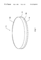
- FIG. 1 is a perspective view of the preferred embodiment prior to bonding the layers
- FIG. 2 is a cross sectional view of the preferred embodiment after cooling of the layers
- FIG. 3 is a cross sectional view of an alternate embodiment of the present invention.
- FIG. 4 is a cross sectional view of an alternate embodiment of the present invention.
- FIG. 5 is a cross sectional view showing the manufacturing process of the present invention.
- FIG. 6 is perspective view showing an alternate embodiment of the present invention.
- FIG. 7 is a top view showing a plurality of prestressed wafers connected to form a larger wafer.
- FIG. 8 is a side view showing three of the prestressed wafers in a stacked configuration.
- FIG. 1 shows a piezoelectric device 10 according to the present invention prior to being processed.
- the device includes four layers, a piezoelectric layer 12 , a prestressing layer 14 and two electrode layers 18 a and 18 b.
- the piezoelectric layer 12 can be made from a disk of piezoelectric material commercially available from Aura Ceramics (C3900 material) or Morgan Matrox. Alternatively, this layer can be made from piezoelectric material that was first ground to a fine powder and subsequently consolidated into a layer by compression bonding the powder with an adhesive such as a polyimide, as shown in “Tough, Soluble, Aromatic, Thermoplastic Copolyimides”, Ser. No. 08/359,752, filed Dec. 16, 1994.
- the adhesive binder makes up a very small fraction, typically 5 percent by weight, of the finished piezoelectric layer 12 .
- This latter approach is attractive since the required bonding operation can simply be performed simultaneously with other needed bonding operations discussed in the next paragraph.
- other ferroelectric materials including piezostrictive materials may be used to form this layer.
- the prestressing layer 14 can be made of a mechanically strong adhesive such as a polyimide. Thermoplastics, thermosets and braze alloys may also be used for this layer 14 . Additionally, multiple prestress layers 14 may be used to provide increased prestress.
- the adhesive is wet-coated or a thin film is melted onto one surface of the piezoelectric layer 12 and then bonded to it at an elevated temperature which is dependent on the adhesive being used and allows the material to undergo cure, drying, and/or melt flow.
- the layer of adhesive thus formed is typically twelve microns thick, but can range in thickness from a few microns to several mm.
- the prestressing layer 14 of adhesive can be reinforced primarily to allow augmenting the level of prestress, but also for mechanical toughness and decreased hysteresis. To accomplish this, a thin layer of reinforcing material 16 is fused or bonded onto (FIG. 3 ), or into (FIG. 4 ), the prestressing layer 14 .
- reinforcing materials include, but are not limited to, plastics, ceramics, metals and combinations of these materials such as aluminum sheet stock and carbon fibers. Bonding of the reinforcing material 16 can occur simultaneously with the bonding of the piezoelectric to the prestressing layer.
- the adhesive layer allows the thin ceramic wafer to be cut to shape without chipping or fracturing using conventional cutting tools like scissors and pattern cutters allowing tailor-made shapes rather than molded shapes.
- This method enables techniques to be used which allow the pattern building of 3-dimensional objects from the consolidation of the 2-dimensional flat ceramic shapes.
- These layers can also offer additional environmental protection which allows these devices to be used in harsh conditions. If the adhesive layer used is a good dielectric, the chances of internal and external arcing due to the applied voltage are reduced.
- the piezoelectric device 10 contains two electrodes 18 a and 18 b.
- the electrodes 18 a and 18 b can be of the more conventional vacuum-deposited metal type, and can be applied onto the piezoelectric layer 12 prior to application of the prestressing layer 14 .
- the electrodes can be a graphite or metal-plus-adhesive mixture such as silver epoxy, which is an excellent conductor.
- This alternate technique has the advantage that the conductive adhesive mixture can be coated onto the piezoelectric layer 12 and subsequently bonded to the piezoelectric layer 12 , simultaneous with the bonding of the prestressing 14 and piezoelectric layers 12 .
- Multiple or patterned electrodes may also be used if necessary for the desired application.
- the amount of prestress in the piezoelectric material can be tailored during manufacture in order to maximize the output motion and efficiency of the final device.
- the material layers may be formed on a curve-shaped mold.
- a description typical of fabricating a prestressed device 10 by hand is provided here and shown in FIG. 5.
- a molding surface 20 is selected for the amount of curvature needed to provide the desired prestress.
- the prestress reinforcing layer 16 of aluminum foil is then placed on top of the molding surface 20 .
- the adhesive prestress layer 14 made from a polyimide as described in “Tough, Soluble, Aromatic, Thermoplastic Copolyimides”, Ser. No. 08/359,752, filed Dec. 16, 1994 is placed on top of the reinforcing layer 16 .
- the electrode layer 18 b of silver is vacuum deposited on the lower surface of the piezoelectric wafer 12 (this step is unnecessary if pre-electroded piezoelectric wafers are being used).
- the piezoelectric wafer 12 is placed on top of the adhesive prestress layer 14 . Finally, an electrode layer 18 a of silver is vacuum deposited on the upper surface of piezoelectric wafer 12 , if necessary.
- a sheet of high temperature material 22 such as Kapton® (DuPont), is placed over the stack and is sealed using high temperature bagging tape 24 to produce a vacuum bag. The assembly is placed into an oven and the air in the Kapton® bag 22 is evacuated through vacuum port 26 . The oven is heated to 300° C. to melt the adhesive and bond the assembly. Upon cooling, the assembly undergoes further prestressing, and the resulting piezoelectric device is removed from the vacuum bag and mold.
- ferroelectric wafers are typically poled as received from the vendor, they must be repoled following thermal treatment in the prestress process.
- the poling is done at an elevated temperature with a DC voltage sufficient to induce dipole orientation. After poling, the wafer is cooled to room temperature in the presence of the electric field to preserve the induced orientation.
- the DC field strength employed in the polarization is selected to obtain optimum polarization without exceeding the field at which dielectric breakdown occurs in the material at a given poling temperature.
- the amount and type of input voltage per unit of deflection, motion, force and output voltage, current, or power conversion can be adjusted by varying the thickness and/or number of layers of the piezoelectric, the number of layers and/or thickness of the prestress layer, the prestress material, the piezoelectric composition and the curvature and shape of the molding surface.
- the curvature of the mold By varying the curvature of the mold, the prestress imparted to the finished piezoelectric device is varied.
- the output motion and mechanical force can also be varied.
- the piezoelectric and prestressing layers move with respect to each other and upon cooling bond together with additional prestress. This method of making devices has shown substantial increase of output motion of otherwise identical piezoelectric devices.
- a cylindrical bender mode may be emphasized by prestressing in only one direction which can be done by bending the layers over a cylindrical molding surface during the heating cycle.
- the prestressing layer 14 being under the piezoelectric layer 12 has a tighter radius of curvature and prestresses more in one direction thus forming the bender.
- These cylindrical mode benders are typically shapes other than circular as shown in FIG. 6 .
- a number of individual, polygon-shaped piezoelectric devices 28 can be grouped into a large-area mosaic by joining their appropriate edges as shown in FIG. 7 .
- One useful method for edge attachment is the use of a single reinforcing layer that covers the entire mosaic.
- FIG. 8 shows three devices in this stacked configuration.
- a compliant layer 30 such as an elastomer, i.e. silicone rubber, which allows one layer to move relative to the other.
- the individual devices 10 remain electrically isolated from each other; one or more of the devices 10 can act as a motion feedback sensor.
- large flexible sheets may be produced for use in low-frequency actuator applications (i.e. noise canceling devices or loud speakers).
- This can be accomplished by using large flat molds for consolidation or a continuous roll process. Molded parts can be bonded together by heating them to soften and/or cure the binder adhesive while pressing them together.
- Ferroelectric devices made from the present method can be used in pumps, valves, brakes, motors, sensors, actuators, optics, acoustic transducers, and active structures.
Abstract
Description
Claims (8)
Priority Applications (1)
| Application Number | Priority Date | Filing Date | Title |
|---|---|---|---|
| US08/797,553 US6734603B2 (en) | 1995-04-04 | 1997-01-24 | Thin layer composite unimorph ferroelectric driver and sensor |
Applications Claiming Priority (2)
| Application Number | Priority Date | Filing Date | Title |
|---|---|---|---|
| US08/416,598 US5632841A (en) | 1995-04-04 | 1995-04-04 | Thin layer composite unimorph ferroelectric driver and sensor |
| US08/797,553 US6734603B2 (en) | 1995-04-04 | 1997-01-24 | Thin layer composite unimorph ferroelectric driver and sensor |
Related Parent Applications (1)
| Application Number | Title | Priority Date | Filing Date |
|---|---|---|---|
| US08/416,598 Continuation US5632841A (en) | 1995-04-04 | 1995-04-04 | Thin layer composite unimorph ferroelectric driver and sensor |
Publications (2)
| Publication Number | Publication Date |
|---|---|
| US20010043027A1 US20010043027A1 (en) | 2001-11-22 |
| US6734603B2 true US6734603B2 (en) | 2004-05-11 |
Family
ID=23650582
Family Applications (2)
| Application Number | Title | Priority Date | Filing Date |
|---|---|---|---|
| US08/416,598 Expired - Lifetime US5632841A (en) | 1995-04-04 | 1995-04-04 | Thin layer composite unimorph ferroelectric driver and sensor |
| US08/797,553 Expired - Fee Related US6734603B2 (en) | 1995-04-04 | 1997-01-24 | Thin layer composite unimorph ferroelectric driver and sensor |
Family Applications Before (1)
| Application Number | Title | Priority Date | Filing Date |
|---|---|---|---|
| US08/416,598 Expired - Lifetime US5632841A (en) | 1995-04-04 | 1995-04-04 | Thin layer composite unimorph ferroelectric driver and sensor |
Country Status (7)
| Country | Link |
|---|---|
| US (2) | US5632841A (en) |
| EP (2) | EP1324402B1 (en) |
| JP (1) | JP4109717B2 (en) |
| AU (1) | AU5386596A (en) |
| CA (1) | CA2217472C (en) |
| DE (2) | DE69637114T2 (en) |
| WO (1) | WO1996031333A1 (en) |
Cited By (15)
| Publication number | Priority date | Publication date | Assignee | Title |
|---|---|---|---|---|
| US20040022408A1 (en) * | 2002-05-02 | 2004-02-05 | Mango Louis A. | Frame structure |
| US20040056567A1 (en) * | 2002-09-20 | 2004-03-25 | Menzel Christoph P. | Bending actuators and sensors constructed from shaped active materials and methods for making the same |
| US20040130242A1 (en) * | 2002-12-13 | 2004-07-08 | Palo Alto Research Center, Inc. | Piezoelectric transducers and methods of manufacture |
| US20040130243A1 (en) * | 2002-12-13 | 2004-07-08 | Palo Alto Research Center, Inc. | Piezoelectric transducers |
| US20060056999A1 (en) * | 2000-09-18 | 2006-03-16 | Par Technologies Llc | Piezoelectric actuator and pump using same |
| US20060131530A1 (en) * | 2000-09-18 | 2006-06-22 | Par Technologies, Llc | Piezoelectric actuator and pump using same |
| US20060232171A1 (en) * | 2005-04-13 | 2006-10-19 | Par Technologies, Llc | Piezoelectric diaphragm assembly with conductors on flexible film |
| US20070129681A1 (en) * | 2005-11-01 | 2007-06-07 | Par Technologies, Llc | Piezoelectric actuation of piston within dispensing chamber |
| US20070145861A1 (en) * | 2005-11-18 | 2007-06-28 | Par Technologies, Llc | Human powered piezoelectric power generating device |
| US7258533B2 (en) | 2004-12-30 | 2007-08-21 | Adaptivenergy, Llc | Method and apparatus for scavenging energy during pump operation |
| US20080246367A1 (en) * | 2006-12-29 | 2008-10-09 | Adaptivenergy, Llc | Tuned laminated piezoelectric elements and methods of tuning same |
| US20090148320A1 (en) * | 2006-03-07 | 2009-06-11 | Influent Corporation | Fluidic Energy Transfer Devices |
| US20090174289A1 (en) * | 2007-12-28 | 2009-07-09 | Adaptivenergy Llc | Magnetic impulse energy harvesting device and method |
| US20090313798A1 (en) * | 2006-12-29 | 2009-12-24 | Adaptiv Energy ,Llc | Rugged piezoelectric actuators and methods of fabricating same |
| US20100271735A1 (en) * | 2009-04-24 | 2010-10-28 | Magnecomp Corporation | Wireless Microactuator Motor Assembly for Use in a Hard Disk Drive Suspension, and Mechanical and Electrical Connections Thereto |
Families Citing this family (145)
| Publication number | Priority date | Publication date | Assignee | Title |
|---|---|---|---|---|
| US6791098B2 (en) | 1994-01-27 | 2004-09-14 | Cymer, Inc. | Multi-input, multi-output motion control for lithography system |
| US6781285B1 (en) | 1994-01-27 | 2004-08-24 | Cymer, Inc. | Packaged strain actuator |
| US6959484B1 (en) * | 1994-01-27 | 2005-11-01 | Cymer, Inc. | System for vibration control |
| US6420819B1 (en) * | 1994-01-27 | 2002-07-16 | Active Control Experts, Inc. | Packaged strain actuator |
| US6404107B1 (en) | 1994-01-27 | 2002-06-11 | Active Control Experts, Inc. | Packaged strain actuator |
| US5802195A (en) * | 1994-10-11 | 1998-09-01 | The United States Of America As Represented By The Administrator Of The National Aeronautics And Space Administration | High displacement solid state ferroelectric loudspeaker |
| US5713150A (en) | 1995-12-13 | 1998-02-03 | Defense Technologies, Llc | Combined mechanical and Electro-mechanical firing mechanism for a firearm |
| US6071087A (en) * | 1996-04-03 | 2000-06-06 | The United States Of America As Represented By The Administrator Of The National Aeronautics And Space Administration | Ferroelectric pump |
| US5961096A (en) | 1996-04-03 | 1999-10-05 | The United States Of America As Represented By The Administrator Of The National Aeronautics And Space Administration | Ferroelectric fluid flow control valve |
| WO1997044987A1 (en) * | 1996-05-24 | 1997-11-27 | Lesinski S George | Improved microphones for an implantable hearing aid |
| DE69739657D1 (en) * | 1996-07-19 | 2009-12-31 | Armand P Neukermans | BIO-COMPATIBLE, IMPLANTABLE MICRO DRIVE FOR A HEARING DEVICE |
| US6781284B1 (en) | 1997-02-07 | 2004-08-24 | Sri International | Electroactive polymer transducers and actuators |
| US5849125A (en) * | 1997-02-07 | 1998-12-15 | Clark; Stephen E. | Method of manufacturing flextensional transducer using pre-curved piezoelectric ceramic layer |
| US6213564B1 (en) * | 1997-04-15 | 2001-04-10 | Face International Corp | Anti-lock brake system with piezoelectric brake actuator |
| US6030480A (en) * | 1997-07-25 | 2000-02-29 | Face International Corp. | Method for manufacturing multi-layered high-deformation piezoelectric actuators and sensors |
| US6060811A (en) * | 1997-07-25 | 2000-05-09 | The United States Of America As Represented By The United States National Aeronautics And Space Administration | Advanced layered composite polylaminate electroactive actuator and sensor |
| DE19732513C2 (en) * | 1997-07-29 | 2002-04-11 | Eurocopter Deutschland | Method of making a composite structure |
| US6179943B1 (en) * | 1997-07-30 | 2001-01-30 | The Boeing Company | Method for forming a composite acoustic panel |
| US5918502A (en) * | 1997-09-03 | 1999-07-06 | Face International Corporation | Footwear incorporating piezoelectric spring system |
| US6209994B1 (en) * | 1997-09-17 | 2001-04-03 | Seiko Epson Corporation | Micro device, ink-jet printing head, method of manufacturing them and ink-jet recording device |
| JPH11304825A (en) * | 1997-09-30 | 1999-11-05 | Seiko Instruments Inc | Semiconductor distortion sensor and its manufacture, and scanning probe microscope |
| JP3700910B2 (en) * | 1997-10-16 | 2005-09-28 | セイコーインスツル株式会社 | Semiconductor strain sensor, manufacturing method thereof, and scanning probe microscope |
| US6291930B1 (en) | 1998-08-13 | 2001-09-18 | Oceaneering International, Inc. | Low voltage piezoelectric bender elements and unit cells |
| US6114494A (en) * | 1998-12-03 | 2000-09-05 | Ranbar Electrical Materials, Inc. | Polyimide material and method of manufacture |
| CA2354076A1 (en) | 1998-12-11 | 2000-06-22 | The Government Of The United States Represented By The Administrator Of The National Aeronautics And Space Administration (Nasa) | Ferroelectric pump |
| US6571639B1 (en) * | 1999-03-01 | 2003-06-03 | Luna Innovations, Inc. | Fiber optic system |
| US6128251A (en) * | 1999-04-16 | 2000-10-03 | Syntron, Inc. | Solid marine seismic cable |
| US6151277A (en) * | 1999-04-16 | 2000-11-21 | Syntron, Inc. | Hydrophone with ferroelectric sensor |
| US6293632B1 (en) * | 1999-06-11 | 2001-09-25 | John F. Grote | Vehicular brake-by-wire system |
| US6425553B1 (en) | 1999-08-20 | 2002-07-30 | West Virginia University | Piezoelectric actuators for circulation controlled rotorcraft |
| US6245172B1 (en) * | 1999-08-26 | 2001-06-12 | Face International Corp. | Method and apparatus for manufacturing multi-layered high deformation piezoelectric actuators and sensors |
| TW511391B (en) | 2000-01-24 | 2002-11-21 | New Transducers Ltd | Transducer |
| GB0117665D0 (en) * | 2001-07-20 | 2001-09-12 | New Transducers Ltd | Passenger vehicle |
| US7151837B2 (en) * | 2000-01-27 | 2006-12-19 | New Transducers Limited | Loudspeaker |
| US6965678B2 (en) * | 2000-01-27 | 2005-11-15 | New Transducers Limited | Electronic article comprising loudspeaker and touch pad |
| US6885753B2 (en) * | 2000-01-27 | 2005-04-26 | New Transducers Limited | Communication device using bone conduction |
| US6865277B2 (en) | 2000-01-27 | 2005-03-08 | New Transducers Limited | Passenger vehicle |
| US6400062B1 (en) | 2000-03-21 | 2002-06-04 | Caterpillar Inc. | Method and apparatus for temperature compensating a piezoelectric device |
| US6512323B2 (en) | 2000-03-22 | 2003-01-28 | Caterpillar Inc. | Piezoelectric actuator device |
| US6376966B1 (en) | 2000-05-22 | 2002-04-23 | Caterpillar, Inc. | Method and apparatus for controlling a piezoelectric device |
| DE10025561A1 (en) | 2000-05-24 | 2001-12-06 | Siemens Ag | Self-sufficient high-frequency transmitter |
| US6356007B1 (en) | 2000-05-30 | 2002-03-12 | Young & Franklin, Inc. | Bi-stable snap over actuator |
| US6739729B1 (en) * | 2000-06-27 | 2004-05-25 | The Boeing Company | Composite backed prestressed mirror for solar facet |
| CN1222003C (en) * | 2000-07-13 | 2005-10-05 | 克拉克·戴维斯·博伊德 | Self power feeding switch element |
| US20020038990A1 (en) * | 2000-08-18 | 2002-04-04 | National Aeronautics And Space Administration | Piezoelectric composite device and method for making same |
| DE50113227D1 (en) * | 2000-09-18 | 2007-12-20 | Caterpillar Inc | Method for producing a ferroelectric device |
| CA2977307C (en) | 2000-11-21 | 2018-09-25 | Bradbury R. Face | Self-powered trainable switching network |
| US6376969B1 (en) | 2001-02-05 | 2002-04-23 | Caterpillar Inc. | Apparatus and method for providing temperature compensation of a piezoelectric device |
| US6771005B2 (en) * | 2001-02-14 | 2004-08-03 | Caterpillar Inc | Apparatus and method for adjusting the pre-load of a spring |
| DE10206977B4 (en) * | 2001-02-24 | 2009-04-02 | Caterpillar Inc., Peoria | Method for producing a multilayer component and subsequently manufactured component |
| US6847155B2 (en) * | 2001-04-24 | 2005-01-25 | Clemson University | Electroactive apparatus and methods |
| DE50212202D1 (en) * | 2001-05-11 | 2008-06-19 | Caterpillar Inc | Method for producing a flat multilayer bending transducer and corresponding bending transducer |
| US7233097B2 (en) * | 2001-05-22 | 2007-06-19 | Sri International | Rolled electroactive polymers |
| US6717337B2 (en) | 2001-05-23 | 2004-04-06 | The United States Of America As Represented By The Secretary Of The Navy | Piezoelectric acoustic actuator |
| GB0115858D0 (en) * | 2001-06-28 | 2001-08-22 | Pbt Ip Ltd | Piezo-electric device and method of construction thereof |
| IL159658A0 (en) * | 2001-07-03 | 2004-06-01 | Self-powered switch initiation system | |
| DE20202297U1 (en) * | 2001-09-07 | 2002-08-29 | Drei S Werk Praez Swerkzeuge G | Flat actuator or sensor with internal preload |
| DE10150128C2 (en) * | 2001-10-11 | 2003-10-02 | Enocean Gmbh | Wireless sensor system |
| WO2003037212A2 (en) | 2001-10-30 | 2003-05-08 | Lesinski George S | Implantation method for a hearing aid microactuator implanted into the cochlea |
| KR100401808B1 (en) * | 2001-11-28 | 2003-10-17 | 학교법인 건국대학교 | Curved Shape Actuator Device Composed of Electro Active Layer and Fiber Composite Layers |
| US6715466B2 (en) | 2001-12-17 | 2004-04-06 | Caterpillar Inc | Method and apparatus for operating an internal combustion engine exhaust valve for braking |
| US6794795B2 (en) * | 2001-12-19 | 2004-09-21 | Caterpillar Inc | Method and apparatus for exciting a piezoelectric material |
| US6771007B2 (en) * | 2002-04-17 | 2004-08-03 | The Boeing Company | Vibration induced perpetual energy resource |
| US7429801B2 (en) * | 2002-05-10 | 2008-09-30 | Michelin Richerche Et Technique S.A. | System and method for generating electric power from a rotating tire's mechanical energy |
| US7096727B2 (en) * | 2002-05-10 | 2006-08-29 | Michelin Recherche Et Technique S.A. | System and method for generating electric power from a rotating tire's mechanical energy |
| US6807853B2 (en) * | 2002-05-10 | 2004-10-26 | Michelin Recherche Et Technique S.A. | System and method for generating electric power from a rotating tire's mechanical energy using piezoelectric fiber composites |
| US20030226987A1 (en) | 2002-06-06 | 2003-12-11 | Gallmeyer Christopher F. | Method and apparatus for seat detection and soft seating in a piezoelectric device actuated valve system |
| US6803700B2 (en) * | 2002-06-06 | 2004-10-12 | Caterpillar Inc. | Piezoelectric device |
| US20040003786A1 (en) * | 2002-06-18 | 2004-01-08 | Gatecliff George W. | Piezoelectric valve actuation |
| US6811093B2 (en) * | 2002-10-17 | 2004-11-02 | Tecumseh Products Company | Piezoelectric actuated fuel injectors |
| US20040075367A1 (en) * | 2002-10-17 | 2004-04-22 | Rado Gordon E. | Piezoelectric power generating device for a single cylinder engine |
| US7215250B2 (en) * | 2002-11-22 | 2007-05-08 | Sensormatic Electronics Corporation | Proximity detaching for electronic article surveillance tags |
| FR2848337B1 (en) * | 2002-12-09 | 2005-09-09 | Commissariat Energie Atomique | METHOD FOR PRODUCING A COMPLEX STRUCTURE BY ASSEMBLING STRESS STRUCTURES |
| US20040125472A1 (en) * | 2002-12-12 | 2004-07-01 | R. Todd Belt | Actuated deformable membrane mirror |
| US20040120836A1 (en) * | 2002-12-18 | 2004-06-24 | Xunhu Dai | Passive membrane microvalves |
| US7070674B2 (en) * | 2002-12-20 | 2006-07-04 | Caterpillar | Method of manufacturing a multi-layered piezoelectric actuator |
| US20040125509A1 (en) * | 2002-12-27 | 2004-07-01 | Kr Precision Public Company Limited | Method for fabricating multilayered thin film PZT structures for small form factors |
| US6994762B2 (en) * | 2003-02-10 | 2006-02-07 | The Boeing Company | Single crystal piezo (SCP) apparatus and method of forming same |
| JP4003686B2 (en) * | 2003-04-10 | 2007-11-07 | 株式会社村田製作所 | Piezoelectric electroacoustic transducer |
| DK1751843T3 (en) * | 2003-08-29 | 2012-12-17 | Stanford Res Inst Int | Pre-load of electroactive polymer |
| US20050087019A1 (en) * | 2003-10-24 | 2005-04-28 | Face Bradbury R. | Self-powered vibration monitoring system |
| US7059664B2 (en) | 2003-12-04 | 2006-06-13 | General Motors Corporation | Airflow control devices based on active materials |
| US7118652B2 (en) * | 2003-12-04 | 2006-10-10 | General Motors Corporation | Airflow control devices based on active materials |
| US6979050B2 (en) * | 2003-12-04 | 2005-12-27 | General Motors Corporation | Airflow control devices based on active materials |
| WO2005067074A1 (en) * | 2004-01-09 | 2005-07-21 | Jari Juuti | Electroactive component |
| ATE479201T1 (en) * | 2004-03-02 | 2010-09-15 | Piezoelectric Technology Co Lt | SMALL PIEZOELECTRIC OR ELECTROSTRICTION LINEAR MOTOR |
| US20050225201A1 (en) * | 2004-04-02 | 2005-10-13 | Par Technologies, Llc | Piezoelectric devices and methods and circuits for driving same |
| US7287965B2 (en) * | 2004-04-02 | 2007-10-30 | Adaptiv Energy Llc | Piezoelectric devices and methods and circuits for driving same |
| US7312554B2 (en) * | 2004-04-02 | 2007-12-25 | Adaptivenergy, Llc | Piezoelectric devices and methods and circuits for driving same |
| US7290993B2 (en) * | 2004-04-02 | 2007-11-06 | Adaptivenergy Llc | Piezoelectric devices and methods and circuits for driving same |
| US20050258715A1 (en) * | 2004-05-19 | 2005-11-24 | Schlabach Roderic A | Piezoelectric actuator having minimal displacement drift with temperature and high durability |
| US7692559B2 (en) * | 2004-06-19 | 2010-04-06 | Face International Corp | Self-powered switch initiation system |
| US7126497B2 (en) * | 2004-06-19 | 2006-10-24 | Face International Corp. | Self-powered switch initiation system |
| US20050285728A1 (en) * | 2004-06-29 | 2005-12-29 | Tyndall Patrick A | Power conversion from piezoelectric source |
| US7483545B2 (en) * | 2004-07-07 | 2009-01-27 | Tadashi Nagaoka | Acoustic diaphragm |
| US7138911B2 (en) * | 2004-08-04 | 2006-11-21 | Michelin Recherche Et Technique S.A. | Power conversion from piezoelectric source with multi-stage storage |
| JP4756309B2 (en) * | 2004-08-20 | 2011-08-24 | 独立行政法人産業技術総合研究所 | High sensitivity piezoelectric element |
| US7854467B2 (en) * | 2004-11-05 | 2010-12-21 | General Motors Corporation | Airflow control devices based on active materials |
| US20060147329A1 (en) * | 2004-12-30 | 2006-07-06 | Tanner Edward T | Active valve and active valving for pump |
| US20060180953A1 (en) * | 2005-02-11 | 2006-08-17 | The Regents Of The University Of California | System and method for constructing and operating a high performance piezoelectric actuator |
| US7368860B2 (en) * | 2005-02-11 | 2008-05-06 | The Regents Of The University Od California | High performance piezoelectric actuator |
| US7302744B1 (en) | 2005-02-18 | 2007-12-04 | The United States Of America Represented By The Secretary Of The Navy | Method of fabricating an acoustic transducer array |
| US7321185B2 (en) * | 2005-03-04 | 2008-01-22 | United States Of America As Represented By The Administrator Of The National Aeronautics And Space Administration | Active multistable twisting device |
| WO2006097522A1 (en) * | 2005-03-18 | 2006-09-21 | Bae Systems Plc | An actuator |
| US20060232166A1 (en) * | 2005-04-13 | 2006-10-19 | Par Technologies Llc | Stacked piezoelectric diaphragm members |
| US7822215B2 (en) * | 2005-07-07 | 2010-10-26 | Face International Corp | Bone-conduction hearing-aid transducer having improved frequency response |
| US20070075286A1 (en) * | 2005-10-04 | 2007-04-05 | Par Technologies, Llc | Piezoelectric valves drive |
| US7278679B2 (en) * | 2005-10-26 | 2007-10-09 | Ford Global Technologies, Llc | Automotive vehicle with structural panel having selectively deployable shape memory alloy elements |
| DE102005061752A1 (en) | 2005-12-21 | 2007-07-05 | Eads Deutschland Gmbh | Three-dimensional Stapelpiezoelement and piezoelectric actuator with such a Stapelpiezoelement |
| US20080062013A1 (en) * | 2006-03-10 | 2008-03-13 | Face Bradbury R | Wall switch for wired and self-powered wireless controllers with recessed and flush mounting |
| US20080084138A1 (en) * | 2006-10-10 | 2008-04-10 | Micallef Joseph A | Apparatus For Piezoelectric Generation of Power To Propel An Automobile and Method of Making |
| WO2008154338A1 (en) * | 2007-06-07 | 2008-12-18 | Piezo Resonance Innovations, Inc. | Eye surgical tool |
| EP2174360A4 (en) | 2007-06-29 | 2013-12-11 | Artificial Muscle Inc | Electroactive polymer transducers for sensory feedback applications |
| US8282153B2 (en) * | 2007-08-31 | 2012-10-09 | GM Global Technology Operations LLC | Active material based seam concealment device |
| DE102007061920A1 (en) * | 2007-12-21 | 2009-06-25 | Paritec Gmbh | Chamber, pump with chamber and method for the production of chambers |
| KR100984333B1 (en) * | 2008-07-18 | 2010-09-30 | 국방과학연구소 | Electromechanical Transducer and Manufacturing Method of the Same |
| US8680749B2 (en) * | 2008-09-03 | 2014-03-25 | National Institute Of Aerospace Associates | Piezoelectric multilayer-stacked hybrid actuation/transduction system |
| WO2010034331A1 (en) * | 2008-09-26 | 2010-04-01 | Imi Intelligent Medical Implants Ag | Electrode array and method of manufacturing same |
| EP2239793A1 (en) | 2009-04-11 | 2010-10-13 | Bayer MaterialScience AG | Electrically switchable polymer film structure and use thereof |
| EP2622219B1 (en) | 2010-09-27 | 2021-08-11 | Techtonic Pty Ltd | Undulatory structures |
| CA2828809A1 (en) | 2011-03-01 | 2012-09-07 | Francois EGRON | Automated manufacturing processes for producing deformable polymer devices and films |
| CN103703404A (en) | 2011-03-22 | 2014-04-02 | 拜耳知识产权有限责任公司 | Electroactive polymer actuator lenticular system |
| DE102011078706B4 (en) * | 2011-07-05 | 2017-10-19 | Airbus Defence and Space GmbH | PROCESS AND MANUFACTURING DEVICE FOR PRODUCING A MULTILAYER ACTUATOR |
| US8659211B1 (en) * | 2011-09-26 | 2014-02-25 | Image Acoustics, Inc. | Quad and dual cantilever transduction apparatus |
| JP5505559B2 (en) * | 2011-10-11 | 2014-05-28 | 株式会社村田製作所 | Fluid control device and method for adjusting fluid control device |
| WO2013142552A1 (en) | 2012-03-21 | 2013-09-26 | Bayer Materialscience Ag | Roll-to-roll manufacturing processes for producing self-healing electroactive polymer devices |
| US9761790B2 (en) | 2012-06-18 | 2017-09-12 | Parker-Hannifin Corporation | Stretch frame for stretching process |
| WO2014066576A1 (en) | 2012-10-24 | 2014-05-01 | Bayer Intellectual Property Gmbh | Polymer diode |
| US9117468B1 (en) | 2013-03-18 | 2015-08-25 | Magnecomp Corporation | Hard drive suspension microactuator with restraining layer for control of bending |
| US9070394B1 (en) | 2013-03-18 | 2015-06-30 | Magnecomp Corporation | Suspension microactuator with wrap-around electrode on inactive constraining layer |
| US10607642B2 (en) | 2013-03-18 | 2020-03-31 | Magnecomp Corporation | Multi-layer PZT microactuator with active PZT constraining layers for a DSA suspension |
| US9330698B1 (en) | 2013-03-18 | 2016-05-03 | Magnecomp Corporation | DSA suspension having multi-layer PZT microactuator with active PZT constraining layers |
| US9741376B1 (en) | 2013-03-18 | 2017-08-22 | Magnecomp Corporation | Multi-layer PZT microactuator having a poled but inactive PZT constraining layer |
| US9330694B1 (en) | 2013-03-18 | 2016-05-03 | Magnecomp Corporation | HDD microactuator having reverse poling and active restraining layer |
| US11205449B2 (en) | 2013-03-18 | 2021-12-21 | Magnecomp Corporation | Multi-layer PZT microacuator with active PZT constraining layers for a DSA suspension |
| KR101496814B1 (en) | 2013-07-29 | 2015-02-27 | 삼성전기주식회사 | Multilayered ceramic capacitor, the method of the same and board for mounting the same |
| US9457887B2 (en) * | 2014-03-05 | 2016-10-04 | Toyota Motor Engineering & Manufacturing North America, Inc. | Smart material trailing edge variable chord morphing wing |
| US20170238651A1 (en) * | 2014-12-25 | 2017-08-24 | Chih-Hua Hsieh | Insole with heat generating system |
| US20160183629A1 (en) * | 2014-12-25 | 2016-06-30 | Chih-Hua Hsieh | Insole with heat generated by pressing system |
| KR101793225B1 (en) * | 2015-06-10 | 2017-11-03 | 한국과학기술연구원 | Curved piezoelectric device |
| US10128431B1 (en) | 2015-06-20 | 2018-11-13 | Magnecomp Corporation | Method of manufacturing a multi-layer PZT microactuator using wafer-level processing |
| DE102015216846A1 (en) * | 2015-09-03 | 2017-03-09 | Fraunhofer-Gesellschaft zur Förderung der angewandten Forschung e.V. | Arrangement and method for influencing and / or detecting a dynamic or static property of a supporting structure |
| US10681471B2 (en) | 2017-12-22 | 2020-06-09 | Google Llc | Two-dimensional distributed mode actuator |
| US20220276483A1 (en) * | 2021-02-28 | 2022-09-01 | Facebook Technologies, Llc | Deformable lens with an extended range of stability |
| CN113601538B (en) * | 2021-07-30 | 2022-09-13 | 之江实验室 | Optical waveguide type soft optical driver based on micro-nano optical fiber |
Citations (15)
| Publication number | Priority date | Publication date | Assignee | Title |
|---|---|---|---|---|
| US3317762A (en) * | 1964-05-22 | 1967-05-02 | Rudolph E Corwin | Pre-stressed spherical electro-acoustic transducer |
| US3588552A (en) * | 1969-09-23 | 1971-06-28 | Motorola Inc | Prestressed piezoelectric audio transducer |
| US3622815A (en) * | 1970-03-25 | 1971-11-23 | Motorola Inc | High reliability ceramic bender |
| US3631383A (en) * | 1969-07-25 | 1971-12-28 | Bendix Corp | Piezoelectric transducer configuration |
| US3666979A (en) * | 1970-06-17 | 1972-05-30 | Automation Ind Inc | Focused piezoelectric transducer and method of making |
| US4435667A (en) * | 1982-04-28 | 1984-03-06 | Peizo Electric Products, Inc. | Spiral piezoelectric rotary actuator |
| US4539575A (en) * | 1983-06-06 | 1985-09-03 | Siemens Aktiengesellschaft | Recorder operating with liquid drops and comprising elongates piezoelectric transducers rigidly connected at both ends with a jet orifice plate |
| US4716331A (en) * | 1985-12-30 | 1987-12-29 | Motorola Inc. | Electrically variable piezoelectric hybrid capacitor |
| US5042493A (en) * | 1988-06-15 | 1991-08-27 | Matsushita Electric Industrial Co., Ltd. | Ultrasonic probe and method of manufacturing the same |
| US5126000A (en) * | 1988-03-18 | 1992-06-30 | Osamu Takai | Method and apparatus of molding laminated plates |
| US5231326A (en) * | 1992-01-30 | 1993-07-27 | Essex Electronics, Inc. | Piezoelectric electronic switch |
| US5404067A (en) * | 1990-08-10 | 1995-04-04 | Siemens Aktiengesellschaft | Bonded piezoelectric bending transducer and process for producing the same |
| US5589725A (en) * | 1993-02-23 | 1996-12-31 | Research Corporation Tech., Inc. | Monolithic prestressed ceramic devices and method for making same |
| US5687462A (en) * | 1994-01-27 | 1997-11-18 | Active Control Experts, Inc. | Packaged strain actuator |
| US5767612A (en) * | 1994-12-21 | 1998-06-16 | Ngk Insulators, Ltd. | Piezoelectric/electrostrictive film element with a diaphragm having at least one stress releasing end section |
Family Cites Families (4)
| Publication number | Priority date | Publication date | Assignee | Title |
|---|---|---|---|---|
| US3271622A (en) * | 1963-07-05 | 1966-09-06 | Little Inc A | Piezoelectric ballast apparatus |
| US3676722A (en) * | 1969-10-06 | 1972-07-11 | Motorola Inc | Structure for bimorph or monomorph benders |
| JPS5410214B2 (en) * | 1973-10-15 | 1979-05-02 | ||
| US3976898A (en) * | 1975-03-20 | 1976-08-24 | The United States Of America As Represented By The United States Energy Research And Development Administration | Prestressed glass, aezoelectric electrical power source |
-
1995
- 1995-04-04 US US08/416,598 patent/US5632841A/en not_active Expired - Lifetime
-
1996
- 1996-04-04 DE DE69637114T patent/DE69637114T2/en not_active Expired - Fee Related
- 1996-04-04 AU AU53865/96A patent/AU5386596A/en not_active Abandoned
- 1996-04-04 EP EP03001185A patent/EP1324402B1/en not_active Expired - Lifetime
- 1996-04-04 DE DE69629283T patent/DE69629283T2/en not_active Expired - Fee Related
- 1996-04-04 EP EP96910760A patent/EP0819048B1/en not_active Expired - Lifetime
- 1996-04-04 WO PCT/US1996/004725 patent/WO1996031333A1/en active IP Right Grant
- 1996-04-04 CA CA002217472A patent/CA2217472C/en not_active Expired - Fee Related
- 1996-04-04 JP JP53051596A patent/JP4109717B2/en not_active Expired - Fee Related
-
1997
- 1997-01-24 US US08/797,553 patent/US6734603B2/en not_active Expired - Fee Related
Patent Citations (15)
| Publication number | Priority date | Publication date | Assignee | Title |
|---|---|---|---|---|
| US3317762A (en) * | 1964-05-22 | 1967-05-02 | Rudolph E Corwin | Pre-stressed spherical electro-acoustic transducer |
| US3631383A (en) * | 1969-07-25 | 1971-12-28 | Bendix Corp | Piezoelectric transducer configuration |
| US3588552A (en) * | 1969-09-23 | 1971-06-28 | Motorola Inc | Prestressed piezoelectric audio transducer |
| US3622815A (en) * | 1970-03-25 | 1971-11-23 | Motorola Inc | High reliability ceramic bender |
| US3666979A (en) * | 1970-06-17 | 1972-05-30 | Automation Ind Inc | Focused piezoelectric transducer and method of making |
| US4435667A (en) * | 1982-04-28 | 1984-03-06 | Peizo Electric Products, Inc. | Spiral piezoelectric rotary actuator |
| US4539575A (en) * | 1983-06-06 | 1985-09-03 | Siemens Aktiengesellschaft | Recorder operating with liquid drops and comprising elongates piezoelectric transducers rigidly connected at both ends with a jet orifice plate |
| US4716331A (en) * | 1985-12-30 | 1987-12-29 | Motorola Inc. | Electrically variable piezoelectric hybrid capacitor |
| US5126000A (en) * | 1988-03-18 | 1992-06-30 | Osamu Takai | Method and apparatus of molding laminated plates |
| US5042493A (en) * | 1988-06-15 | 1991-08-27 | Matsushita Electric Industrial Co., Ltd. | Ultrasonic probe and method of manufacturing the same |
| US5404067A (en) * | 1990-08-10 | 1995-04-04 | Siemens Aktiengesellschaft | Bonded piezoelectric bending transducer and process for producing the same |
| US5231326A (en) * | 1992-01-30 | 1993-07-27 | Essex Electronics, Inc. | Piezoelectric electronic switch |
| US5589725A (en) * | 1993-02-23 | 1996-12-31 | Research Corporation Tech., Inc. | Monolithic prestressed ceramic devices and method for making same |
| US5687462A (en) * | 1994-01-27 | 1997-11-18 | Active Control Experts, Inc. | Packaged strain actuator |
| US5767612A (en) * | 1994-12-21 | 1998-06-16 | Ngk Insulators, Ltd. | Piezoelectric/electrostrictive film element with a diaphragm having at least one stress releasing end section |
Cited By (24)
| Publication number | Priority date | Publication date | Assignee | Title |
|---|---|---|---|---|
| US20060056999A1 (en) * | 2000-09-18 | 2006-03-16 | Par Technologies Llc | Piezoelectric actuator and pump using same |
| US7191503B2 (en) | 2000-09-18 | 2007-03-20 | Par Technologies, Llc | Method of manufacturing a piezoelectric actuator |
| US20060131530A1 (en) * | 2000-09-18 | 2006-06-22 | Par Technologies, Llc | Piezoelectric actuator and pump using same |
| US7152299B2 (en) * | 2002-05-02 | 2006-12-26 | Harman International Industries, Incorporated | Method of assembling a loudspeaker |
| US20040022408A1 (en) * | 2002-05-02 | 2004-02-05 | Mango Louis A. | Frame structure |
| US20040056567A1 (en) * | 2002-09-20 | 2004-03-25 | Menzel Christoph P. | Bending actuators and sensors constructed from shaped active materials and methods for making the same |
| US20050194869A1 (en) * | 2002-09-20 | 2005-09-08 | Monodrive Inc. | Bending actuators and sensors constructed from shaped active materials and method for making the same |
| US6965189B2 (en) * | 2002-09-20 | 2005-11-15 | Monodrive Inc. | Bending actuators and sensors constructed from shaped active materials and methods for making the same |
| US6967431B2 (en) * | 2002-12-13 | 2005-11-22 | Palo Alto Research Center Inc. | Piezoelectric transducers and methods of manufacture |
| US20040130242A1 (en) * | 2002-12-13 | 2004-07-08 | Palo Alto Research Center, Inc. | Piezoelectric transducers and methods of manufacture |
| US6987348B2 (en) * | 2002-12-13 | 2006-01-17 | Palo Alto Research Center Inc. | Piezoelectric transducers |
| US20040130243A1 (en) * | 2002-12-13 | 2004-07-08 | Palo Alto Research Center, Inc. | Piezoelectric transducers |
| US7258533B2 (en) | 2004-12-30 | 2007-08-21 | Adaptivenergy, Llc | Method and apparatus for scavenging energy during pump operation |
| US20060232171A1 (en) * | 2005-04-13 | 2006-10-19 | Par Technologies, Llc | Piezoelectric diaphragm assembly with conductors on flexible film |
| US20070129681A1 (en) * | 2005-11-01 | 2007-06-07 | Par Technologies, Llc | Piezoelectric actuation of piston within dispensing chamber |
| US20070145861A1 (en) * | 2005-11-18 | 2007-06-28 | Par Technologies, Llc | Human powered piezoelectric power generating device |
| US7345407B2 (en) | 2005-11-18 | 2008-03-18 | Adaptivenergy, Llc. | Human powered piezoelectric power generating device |
| US20090148320A1 (en) * | 2006-03-07 | 2009-06-11 | Influent Corporation | Fluidic Energy Transfer Devices |
| US8272851B2 (en) | 2006-03-07 | 2012-09-25 | Influent Corporation | Fluidic energy transfer devices |
| US20080246367A1 (en) * | 2006-12-29 | 2008-10-09 | Adaptivenergy, Llc | Tuned laminated piezoelectric elements and methods of tuning same |
| US20090313798A1 (en) * | 2006-12-29 | 2009-12-24 | Adaptiv Energy ,Llc | Rugged piezoelectric actuators and methods of fabricating same |
| US20090174289A1 (en) * | 2007-12-28 | 2009-07-09 | Adaptivenergy Llc | Magnetic impulse energy harvesting device and method |
| US20100271735A1 (en) * | 2009-04-24 | 2010-10-28 | Magnecomp Corporation | Wireless Microactuator Motor Assembly for Use in a Hard Disk Drive Suspension, and Mechanical and Electrical Connections Thereto |
| US8189301B2 (en) | 2009-04-24 | 2012-05-29 | Magnecomp Corporation | Wireless microactuator motor assembly for use in a hard disk drive suspension, and mechanical and electrical connections thereto |
Also Published As
| Publication number | Publication date |
|---|---|
| EP0819048B1 (en) | 2003-07-30 |
| EP1324402A2 (en) | 2003-07-02 |
| EP0819048A4 (en) | 1999-09-01 |
| JPH11503272A (en) | 1999-03-23 |
| DE69637114D1 (en) | 2007-07-12 |
| DE69629283D1 (en) | 2003-09-04 |
| US20010043027A1 (en) | 2001-11-22 |
| CA2217472C (en) | 2006-01-10 |
| EP1324402B1 (en) | 2007-05-30 |
| CA2217472A1 (en) | 1996-10-10 |
| JP4109717B2 (en) | 2008-07-02 |
| EP0819048A1 (en) | 1998-01-21 |
| WO1996031333A1 (en) | 1996-10-10 |
| AU5386596A (en) | 1996-10-23 |
| EP1324402A3 (en) | 2005-11-09 |
| DE69637114T2 (en) | 2008-01-24 |
| DE69629283T2 (en) | 2004-05-27 |
| US5632841A (en) | 1997-05-27 |
Similar Documents
| Publication | Publication Date | Title |
|---|---|---|
| US6734603B2 (en) | Thin layer composite unimorph ferroelectric driver and sensor | |
| Hellbaum et al. | Thin layer composite unimorph ferroelectric driver and sensor | |
| US5849125A (en) | Method of manufacturing flextensional transducer using pre-curved piezoelectric ceramic layer | |
| US6512323B2 (en) | Piezoelectric actuator device | |
| CN1120874A (en) | Monolithic prestressed ceramic devices and method for making same | |
| JP5441877B2 (en) | Piezoelectric macro-fiber composite actuator and manufacturing method thereof | |
| JP2738706B2 (en) | Manufacturing method of laminated piezoelectric element | |
| US20110109200A1 (en) | Two- or multi-layer ferrelectret and method for the production thereof | |
| JP2003530805A (en) | Piezoelectric ceramic bending transducer and its use | |
| KR100448108B1 (en) | Piezoelectric acoustic device and a method for manufacture thereof | |
| US7045933B2 (en) | Flat actuator or sensor with internal prestress | |
| Hellbaum et al. | Thin layer composite unimorph ferroelectric driver and sensor | |
| Wilkie et al. | Method of fabricating a piezoelectric composite apparatus | |
| JP3197544B2 (en) | Thermally stable actuator / sensor package and method of manufacturing the same | |
| JP2002186096A (en) | Manufacturing method for piezoelectric speaker and composite piezoelectric sheet | |
| JPH08222770A (en) | Manufacture of thermoelectric element | |
| JPH06316015A (en) | Metallic panel | |
| US6624550B2 (en) | Piezoelectric bending transducer | |
| JPS60128682A (en) | Manufacture of laminating type piezoelectric actuator | |
| TWI259596B (en) | Grating flexible compound piezoelectric ceramic structure and method of manufacturing the same | |
| JPS61205099A (en) | Sounding body | |
| AU2005200740A1 (en) | Method of fabricating a piezoelectric composite apparatus | |
| JPS63294975A (en) | Laminating type piezoelectric element | |
| Wilkie et al. | Method of Fabricating a Composite Apparatus | |
| JPH07135347A (en) | Multialyer piezoelectic actuator |
Legal Events
| Date | Code | Title | Description |
|---|---|---|---|
| AS | Assignment |
Owner name: NATIONAL AERONAUTICS ANS SPACE ADMINISTRATION (NAS Free format text: ASSIGNMENT OF ASSIGNORS INTEREST;ASSIGNORS:HELLBAUM, RICHARD F.;BRYANT, ROBERT G.;FOX, ROBETT L.;AND OTHERS;REEL/FRAME:008480/0375;SIGNING DATES FROM 19970123 TO 19970124 |
|
| FEPP | Fee payment procedure |
Free format text: PAYOR NUMBER ASSIGNED (ORIGINAL EVENT CODE: ASPN); ENTITY STATUS OF PATENT OWNER: LARGE ENTITY |
|
| FPAY | Fee payment |
Year of fee payment: 4 |
|
| FPAY | Fee payment |
Year of fee payment: 8 |
|
| REMI | Maintenance fee reminder mailed | ||
| LAPS | Lapse for failure to pay maintenance fees | ||
| STCH | Information on status: patent discontinuation |
Free format text: PATENT EXPIRED DUE TO NONPAYMENT OF MAINTENANCE FEES UNDER 37 CFR 1.362 |
|
| FP | Lapsed due to failure to pay maintenance fee |
Effective date: 20160511 |