US6764196B2 - Lighting system - Google Patents
Lighting system Download PDFInfo
- Publication number
- US6764196B2 US6764196B2 US10/318,885 US31888502A US6764196B2 US 6764196 B2 US6764196 B2 US 6764196B2 US 31888502 A US31888502 A US 31888502A US 6764196 B2 US6764196 B2 US 6764196B2
- Authority
- US
- United States
- Prior art keywords
- panel
- lighting system
- connector
- leds
- system defined
- Prior art date
- Legal status (The legal status is an assumption and is not a legal conclusion. Google has not performed a legal analysis and makes no representation as to the accuracy of the status listed.)
- Expired - Fee Related
Links
Images


Classifications
-
- F—MECHANICAL ENGINEERING; LIGHTING; HEATING; WEAPONS; BLASTING
- F21—LIGHTING
- F21V—FUNCTIONAL FEATURES OR DETAILS OF LIGHTING DEVICES OR SYSTEMS THEREOF; STRUCTURAL COMBINATIONS OF LIGHTING DEVICES WITH OTHER ARTICLES, NOT OTHERWISE PROVIDED FOR
- F21V19/00—Fastening of light sources or lamp holders
- F21V19/001—Fastening of light sources or lamp holders the light sources being semiconductors devices, e.g. LEDs
- F21V19/0015—Fastening arrangements intended to retain light sources
- F21V19/002—Fastening arrangements intended to retain light sources the fastening means engaging the encapsulation or the packaging of the semiconductor device
-
- E—FIXED CONSTRUCTIONS
- E04—BUILDING
- E04B—GENERAL BUILDING CONSTRUCTIONS; WALLS, e.g. PARTITIONS; ROOFS; FLOORS; CEILINGS; INSULATION OR OTHER PROTECTION OF BUILDINGS
- E04B9/00—Ceilings; Construction of ceilings, e.g. false ceilings; Ceiling construction with regard to insulation
- E04B9/32—Translucent ceilings, i.e. permitting both the transmission and diffusion of light
-
- F—MECHANICAL ENGINEERING; LIGHTING; HEATING; WEAPONS; BLASTING
- F21—LIGHTING
- F21S—NON-PORTABLE LIGHTING DEVICES; SYSTEMS THEREOF; VEHICLE LIGHTING DEVICES SPECIALLY ADAPTED FOR VEHICLE EXTERIORS
- F21S2/00—Systems of lighting devices, not provided for in main groups F21S4/00 - F21S10/00 or F21S19/00, e.g. of modular construction
-
- F—MECHANICAL ENGINEERING; LIGHTING; HEATING; WEAPONS; BLASTING
- F21—LIGHTING
- F21S—NON-PORTABLE LIGHTING DEVICES; SYSTEMS THEREOF; VEHICLE LIGHTING DEVICES SPECIALLY ADAPTED FOR VEHICLE EXTERIORS
- F21S8/00—Lighting devices intended for fixed installation
- F21S8/02—Lighting devices intended for fixed installation of recess-mounted type, e.g. downlighters
- F21S8/026—Lighting devices intended for fixed installation of recess-mounted type, e.g. downlighters intended to be recessed in a ceiling or like overhead structure, e.g. suspended ceiling
-
- F—MECHANICAL ENGINEERING; LIGHTING; HEATING; WEAPONS; BLASTING
- F21—LIGHTING
- F21S—NON-PORTABLE LIGHTING DEVICES; SYSTEMS THEREOF; VEHICLE LIGHTING DEVICES SPECIALLY ADAPTED FOR VEHICLE EXTERIORS
- F21S8/00—Lighting devices intended for fixed installation
- F21S8/04—Lighting devices intended for fixed installation intended only for mounting on a ceiling or the like overhead structures
- F21S8/06—Lighting devices intended for fixed installation intended only for mounting on a ceiling or the like overhead structures by suspension
-
- F—MECHANICAL ENGINEERING; LIGHTING; HEATING; WEAPONS; BLASTING
- F21—LIGHTING
- F21V—FUNCTIONAL FEATURES OR DETAILS OF LIGHTING DEVICES OR SYSTEMS THEREOF; STRUCTURAL COMBINATIONS OF LIGHTING DEVICES WITH OTHER ARTICLES, NOT OTHERWISE PROVIDED FOR
- F21V23/00—Arrangement of electric circuit elements in or on lighting devices
- F21V23/04—Arrangement of electric circuit elements in or on lighting devices the elements being switches
- F21V23/0442—Arrangement of electric circuit elements in or on lighting devices the elements being switches activated by means of a sensor, e.g. motion or photodetectors
-
- F—MECHANICAL ENGINEERING; LIGHTING; HEATING; WEAPONS; BLASTING
- F21—LIGHTING
- F21W—INDEXING SCHEME ASSOCIATED WITH SUBCLASSES F21K, F21L, F21S and F21V, RELATING TO USES OR APPLICATIONS OF LIGHTING DEVICES OR SYSTEMS
- F21W2121/00—Use or application of lighting devices or systems for decorative purposes, not provided for in codes F21W2102/00 – F21W2107/00
- F21W2121/008—Use or application of lighting devices or systems for decorative purposes, not provided for in codes F21W2102/00 – F21W2107/00 for simulation of a starry sky or firmament
-
- F—MECHANICAL ENGINEERING; LIGHTING; HEATING; WEAPONS; BLASTING
- F21—LIGHTING
- F21Y—INDEXING SCHEME ASSOCIATED WITH SUBCLASSES F21K, F21L, F21S and F21V, RELATING TO THE FORM OR THE KIND OF THE LIGHT SOURCES OR OF THE COLOUR OF THE LIGHT EMITTED
- F21Y2105/00—Planar light sources
- F21Y2105/10—Planar light sources comprising a two-dimensional array of point-like light-generating elements
-
- F—MECHANICAL ENGINEERING; LIGHTING; HEATING; WEAPONS; BLASTING
- F21—LIGHTING
- F21Y—INDEXING SCHEME ASSOCIATED WITH SUBCLASSES F21K, F21L, F21S and F21V, RELATING TO THE FORM OR THE KIND OF THE LIGHT SOURCES OR OF THE COLOUR OF THE LIGHT EMITTED
- F21Y2115/00—Light-generating elements of semiconductor light sources
- F21Y2115/10—Light-emitting diodes [LED]
-
- G—PHYSICS
- G02—OPTICS
- G02B—OPTICAL ELEMENTS, SYSTEMS OR APPARATUS
- G02B6/00—Light guides; Structural details of arrangements comprising light guides and other optical elements, e.g. couplings
- G02B6/0001—Light guides; Structural details of arrangements comprising light guides and other optical elements, e.g. couplings specially adapted for lighting devices or systems
- G02B6/0011—Light guides; Structural details of arrangements comprising light guides and other optical elements, e.g. couplings specially adapted for lighting devices or systems the light guides being planar or of plate-like form
- G02B6/0013—Means for improving the coupling-in of light from the light source into the light guide
- G02B6/0015—Means for improving the coupling-in of light from the light source into the light guide provided on the surface of the light guide or in the bulk of it
- G02B6/002—Means for improving the coupling-in of light from the light source into the light guide provided on the surface of the light guide or in the bulk of it by shaping at least a portion of the light guide, e.g. with collimating, focussing or diverging surfaces
- G02B6/0021—Means for improving the coupling-in of light from the light source into the light guide provided on the surface of the light guide or in the bulk of it by shaping at least a portion of the light guide, e.g. with collimating, focussing or diverging surfaces for housing at least a part of the light source, e.g. by forming holes or recesses
-
- G—PHYSICS
- G02—OPTICS
- G02B—OPTICAL ELEMENTS, SYSTEMS OR APPARATUS
- G02B6/00—Light guides; Structural details of arrangements comprising light guides and other optical elements, e.g. couplings
- G02B6/0001—Light guides; Structural details of arrangements comprising light guides and other optical elements, e.g. couplings specially adapted for lighting devices or systems
- G02B6/0011—Light guides; Structural details of arrangements comprising light guides and other optical elements, e.g. couplings specially adapted for lighting devices or systems the light guides being planar or of plate-like form
- G02B6/0066—Light guides; Structural details of arrangements comprising light guides and other optical elements, e.g. couplings specially adapted for lighting devices or systems the light guides being planar or of plate-like form characterised by the light source being coupled to the light guide
- G02B6/0068—Arrangements of plural sources, e.g. multi-colour light sources
-
- Y—GENERAL TAGGING OF NEW TECHNOLOGICAL DEVELOPMENTS; GENERAL TAGGING OF CROSS-SECTIONAL TECHNOLOGIES SPANNING OVER SEVERAL SECTIONS OF THE IPC; TECHNICAL SUBJECTS COVERED BY FORMER USPC CROSS-REFERENCE ART COLLECTIONS [XRACs] AND DIGESTS
- Y10—TECHNICAL SUBJECTS COVERED BY FORMER USPC
- Y10S—TECHNICAL SUBJECTS COVERED BY FORMER USPC CROSS-REFERENCE ART COLLECTIONS [XRACs] AND DIGESTS
- Y10S362/00—Illumination
- Y10S362/80—Light emitting diode
Definitions
- This invention relates to lighting systems and, more specifically, to a lighting system in which a plurality of light elements are embedded in or mounted to a support structure.
- the suspended ceiling typically includes a grid or frame that is formed from a plurality of interlocking, inverted metal “T” beams or rails.
- the grid may be hung from the permanent ceiling by a series of cables or wires that are anchored to the permanent ceiling.
- the “T” beams or rails of the grid define a plurality of open, rectangular-shaped spaces into which ceiling panels or tiles are placed.
- light fixtures are installed in place of several ceiling panels. For example, for every 15 or so ceiling panels, a light fixture is installed.
- the light fixtures typically mount flush to the suspended ceiling, and replace an entire ceiling panel.
- the light fixtures include one or more fluorescent tubes to provide the light, and are similarly supported by the suspended ceiling frame.
- a diffuser or grid may also be provided so as to diffuse the light being emitted by the fluorescent tube(s).
- Electrical power is provided to the light fixtures by running electrical lines to them. In particular, electrical lines are run from a junction or distribution box to the light fixture through the space between the permanent and suspended ceilings.
- fluorescent tubes typically require less power than incandescent bulbs for roughly the same luminescence, they still can be relatively expensive to operate. For example, fluorescent tubes have a limited life. Thus, the tubes must be frequently checked and replaced. Their power consumption, moreover, is not insignificant. As a result, the use of fluorescent tube-based light fixtures contributes to the high operating costs faced by many businesses and other organizations who rent and own office and manufacturing facilities.
- the invention is directed to a lighting system in which a plurality of light elements are embedded within or mounted to a support structure.
- the support structure is a ceiling panel for use with a suspended ceiling
- the light elements are ultra-bright light emitting diodes (LEDs).
- LEDs have lower power requirements and longer lives than fluorescent tubes.
- the panel is generally rectangular in shape and defines first and second opposing surfaces. The LEDs are mounted in the ceiling panel so that the light emitted by each LED projects from the first surface of the ceiling panel. Thus, upon installation of the panel in the grid of the suspended ceiling, the light generated by the LEDs shines down from the panel and into the corresponding space.
- the panel may have a plurality of conical or concave recesses formed in its first surface for receiving the LEDs.
- the recesses may have a reflective surface to increase the amount of light being delivered into the room.
- a conductive strip that may be attached to the second surface of the panel preferably contains electrical leads that wire the LEDs into a series circuit.
- a direct current (DC) voltage is applied to the conductive strip, thereby powering the LEDs embedded within the panel.
- FIG. 1 is a perspective view of a room having a suspended ceiling in accordance with the present invention
- FIG. 2 is a cross-sectional view of a ceiling panel illustrating the light element in detail
- FIG. 3 is an isometric view of a ceiling panel illustrating its first or lower surface
- FIG. 4 is a plan view of the ceiling panel of FIG. 3 illustrating its second or upper surface
- FIG. 5A is a partial isometric view of a grid element and a rail connector
- FIG. 5B is an end view of the rail connector of FIG. 5A;
- FIG. 6 is a partial isometric view of a ceiling panel having a light element in accordance with another embodiment of the present invention.
- FIG. 7 is an electrical wiring diagram of the ceiling panel of FIG. 6;
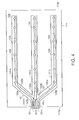
- FIG. 8 is a highly schematic representation of a duty cycle for operating the light element of FIG. 6.
- FIGS. 9 and 10 are isometric views of other embodiments of the light elements and support structures of the present invention.
- FIG. 1 is a perspective view of an office or room 100 illustrating an exemplary embodiment of the present invention.
- the room 100 includes a floor 102 , two opposing side walls 104 and 106 , a back wall 108 and a permanent ceiling 110 .
- Spaced from the permanent ceiling 110 is a suspended ceiling 112 .
- the suspended ceiling 112 is made up of a plurality of ceiling panels 114 held in place by a metal grid or frame 116 .
- the grid 116 consists of a plurality of inverted “T” rails. The rails are interconnected with each other to form rectangular-shaped openings into which the ceiling panels 114 are placed.
- the metal grid 116 hangs from the permanent ceiling 110 by a plurality of cables 118 .
- Each cable 118 has a first end that is anchored to the permanent ceiling 110 and a second end that is attached to the metal grid 116 .
- FIG. 2 is a cross-sectional view of a ceiling panel 114 illustrating a light element 124 embedded therein
- FIG. 3 is an isometric view of the lower surface of ceiling panel 114
- FIG. 4 is a plan view of the upper surface of ceiling panel 114
- FIG. 5A is a partial isometric view of a grid element
- FIG. 5B is an end view of a rail connector.
- Embedded within the ceiling panel 114 are a plurality of light elements 124 .
- the light elements 124 are preferably ultra-bright, light emitting diodes (LEDs) configured to emit “white” light. Each light element 124 , which is best shown in FIG.
- the diode or chip 126 for emitting light, a protective dome 128 , and a base 130 .
- the diode or chip 126 generates the light and is enclosed within the protective dome 128 , which is preferably formed from clear, unbreakable plastic.
- each ceiling panel 114 is substantially rectangular in shape and defines a first or lower surface 134 (FIG. 3) and a second or upper surface 136 (FIG. 4 ).
- the light elements 124 may be arranged in a plurality, e.g., three, equally spaced rows that run substantially parallel to the longer sides of the panel 114 .
- the light elements 124 are preferably embedded within the panel 114 such that the light they emit is directed away from the nominal plane defined by the first or lower surface 134 .
- a plurality of recesses 138 are preferably formed in the ceiling panel 114 in order to receive the light elements 124 .
- Each recess 138 may be conical or concave-shaped, and the light element 124 may be mounted at or near the apex or top of the recess 138 .
- the recesses 138 may be made from a reflective, conical or concave-shaped insert.
- the surface of the recess 138 may be coated or painted with a reflective material so that light from the respective light element 124 is reflected away from the panel 114 .
- Suitable LEDs for use with the present invention are commercially available from The LED Light Company of North Las Vegas, Nev. Such LEDs have a luminous intensity of approximately 1560 to 5600 mcd, and draw approximately 120 milliwatts (mW) of power. Those skilled in the art will recognize that LEDs typically emit light of a single color.
- One known method for the light element 124 to produce white light is to have a highly efficient blue diode combined with a phosphors that gives of a broadband “white” glow when excited by the blue light from the diode. Other methods are also possible.
- the conductive strip 140 Disposed along the second or upper surface 136 of the ceiling panel 114 is a conductive strip 140 (FIG. 4 ).
- the conductive strip 140 preferably has a plurality of segments or legs 141 a-c, such that each segment or leg 141 a-c corresponds to a row of light elements 124 embedded within the respective panel 114 .
- Each segment 141 a-c forming the strip 140 may be ribbon-shaped, and each segment 141 a-c may be joined together at a first end 137 .
- the segments 141 a-c preferably extend a substantial length of the panel 114 .
- Disposed within the conductive strip 140 is at least one wire for electrically connecting the light elements 124 .
- each segment or leg 141 a-c has its own power and its own ground wire. More specifically, segment 141 a has a power wire 132 a and a ground wire 132 b . Segment 141 b has a power wire 133 a and a ground wire 133 b. Segment 141 c has a power wire 135 a and a ground wire 135 b.
- the power and ground wires, e.g., wires 132 a-b, for each segment, e.g., segment 141 a, are used to wire the light elements 124 for the respective segment into a single series circuit.
- One or more current limiting resistors 142 a-c may be added in series to the electrical circuit of each segment or leg 141 a-c.
- the conductive strip 140 is formed from a flexible material, such as plastic, rubber, etc., and is strong enough to support the light elements 124 . That is, the light elements 124 may be fastened or otherwise attached to the conductive strip 140 in a “built-in” manner.
- the conductive strip 140 may further include an adhesive backing for use in attaching the strip 140 to the second or upper surface 136 of the ceiling panel 114 .
- the strip 140 may be bonded or glued to the ceiling panel 114 . Other fastening arrangements or methods could also be utilized.
- Grid 116 is preferably formed from a plurality of interlocking, inverted metal “T” rails 146 (FIG. 5 A).
- Rails 146 include an upright segment 146 a and a base 146 b.
- the rails 146 are hung from the permanent ceiling 110 by cables 118 , and are preferably joined together so as to define a plurality of open, rectangular-shaped spaces into which the panels 114 may be inserted and supported.
- Panels 114 are preferably placed in the spaces defined by the rails 146 so that the panels' first or lower surfaces 134 face the floor 102 of the room 100 . In this way, the light emitted by the light elements 124 is directed in a generally downward direction, thereby illuminating the room 100 .
- a direct current (DC) voltage sufficient to power the light elements 124 embedded within the panels 114 is provided in one or more insulated channels which are manufactured into the metal rails 146 of the grid. Disposed along the rails 146 and the panels 114 , moreover, are corresponding pairs of electrical connectors configured for mating engagement with each other. More specifically, attached to rail 146 are a plurality of spaced-apart rail connectors 148 (FIG. 5 A).
- the rail connectors 148 may be generally serpentine or L-shaped as best shown in FIG.
- a first segment 148 a of the rail connector 148 are a pair of spaced-apart, electrically conductive bands 147 a-b that are preferably arcuate or curved so as to provide a spring or bias action relative to the first segment 148 a of the rail connector 148 .
- the panel connector 150 may also be L-shaped and arranged so that a first segment 150 a (FIG. 3) extends or hangs over an edge 114 a of the panel 114 .
- the panel connector 150 also includes a pair of spaced-apart, electrically conductive bands 151 a-b that may be flat or curved.
- the power wire 132 a , 133 a, 135 a for each segment 141 a-c is coupled to one band 151 b, while the ground wires 132 b , 133 b, 135 b are coupled to the other band 151 a.
- a voltage is applied across the pair of bands 151 a-b of the panel connector 150 .
- each band 151 a-b of the panel connector 150 mate in electrical engagement with a respective band 147 a-b of a rail connector 148 associated with that panel 114 .
- a positive 24 volts DC is then applied to one conductor 143 b of wire 143 , while the other conductor 143 a is electrically grounded.
- each light element 124 would receive approximately 4 volts DC, which is sufficient power to operate the LED.
- the size of the current limiting resistor 142 is preferably selected so that the requisite current flows through the series circuit, e.g., approximately 18 milliamps (mA).
- One or more conventional DC power supplies may be used to provide the voltage to first conductor 143 b.
- the DC power supply may be mounted in the space between the permanent and suspended ceilings 110 , 112 .
- the ground conductor 143 a may be electrically connected to a building ground in a conventional manner.
- Each panel may be powered in a similar manner. That is, one or more rail connectors 148 are positioned along rails 146 to mate with the one or more panel connectors 150 associated with each panel 114 .
- each panel 114 may be provided on each panel 114 .
- DC power and ground may be provided through the metal rails 146 themselves rather than wires 143 .
- attached to the upright portion 146 a of each rail 146 may be one or more rail bands.
- the rail bands may be arcuate or curved so as to provide a spring or bias action relative to the respective rail 146 .
- Coupled to each of the electrically conductive strips 140 that run along the tops of panels 114 are two or more panel bands.
- the panel bands associated with a given strip 140 preferably extend over opposing edges 114 a, 114 b of the panel 114 .
- a circuit is defined between a first rail, the conductive strips 140 , and a second rail.
- a voltage is applied across each pair of adjacent rails of the frame 116 .
- a positive 24 volts DC is applied to a first (i.e., power) rail, while a second (i.e., ground) rail is electrically grounded. That is, the rails alternate power-ground-power-ground, etc.
- Cross rails (not shown) which extend perpendicularly to and are joined to the alternating power and ground rails must be electrically insulated from either the power and/or the ground rails to prevent short-circuiting the power supply to the light elements 124 . Any suitable insulating material may be used. The bottom exposed portion of the T-rails may be insulated to reduce the risk of shock.
- the conductive strip 140 may alternatively be formed from an electrically conductive material such as copper, and leads (not shown) from the light elements 124 may be attached to strip 140 by crimping, soldering, etc.
- the light elements may be controlled on a room-by-room and/or a panel-by-panel basis. That is, all of the light elements in a given room or all of the light elements of a given panel can be controlled so as to be either “on” or “off”. This may be accomplished by providing one or more light switches (not shown) within the room 100 , each switch being configured to govern one or more panels 114 . Alternatively, remotely operable switches may be disposed proximate to the panels 114 and operated by the occupant using a remote control device.
- the occupant can cause the desired lighting to be provided. For example, all of the panels that are located above the occupant's desk or work area may be activated while other panels are turned off. Indeed, the lighting density (i.e., the number of light elements 124 embedded within a single panel 114 ) may be varied depending on the particular lighting requirements in different areas of the room 100 .
- panels 114 may be of various sizes and shapes.
- overhead lighting is provided by a large number of small light elements that are dispersed preferably across the entire ceiling.
- the individual light emitted from all of these small light elements combine to provide sufficient overall light within the space to perform many tasks, such as reading and working at a computer terminal.
- This is in contrast to conventional overhead lighting designs in which just a few large lights fixtures are used to illuminate the space.
- these large light fixtures can produce an uneven light.
- the present invention has been described as using “white” LEDs, colored LEDs may also be advantageously used.
- the light elements 124 embedded within a single panel 114 may have different colors and/or be controlled so as to emit light of different colors.
- a single light element could be configured to selectively emit light of different colors. Different lighting effects can be achieved by varying the color of the light elements 124 embedded within the panels 114 installed in space 100 . Indeed, by varying the intensity of red, blue and green LED chips, light of nearly any desired color, including “white,” can be created.
- FIG. 6 is a partial isometric view of a panel 114 having a multiple diode, light element 160 .
- Light element 160 has a plurality, e.g., three, semiconductor diodes or chips 162 , 164 , 166 each configured to emit light of a different color, e.g., red, blue and green.
- the diodes 162 , 164 , 166 are enclosed inside an outer, protective dome 168 , and are mounted to a base 170 .
- Associated with each diode 162 , 164 , 166 is a wire 132 a , 132 b , 132 c.
- a separate electrically controlled switch 172 , 174 , 176 is disposed along each wire 132 a-c.
- a programmable microcontroller 184 that is operably coupled to each switch 172 , 174 , 176 .
- the microcontroller 184 is configured to control, at relatively high frequencies, the power flowing through each individual wire 132 a-c by opening and closing switches 172 , 174 , 176 .
- the microcontroller 184 is used to pulse (i.e., apply power intermittently to) each of the diodes 162 , 164 , 166 individually such that the “light” resulting from the combined output of diodes 162 , 164 , 166 has a desired color.
- white light is actually a combination of light of each visible color (e.g., red, orange, yellow, green, blue, etc.).
- a “white” LED can also be formed by installing red, blue and green semiconductor diodes within a single bulb or dome, and constantly running all three diodes. The light from each of these “colored” diodes combines to form a “white” light. By pulsing the diodes at different frequencies, however, one color (e.g., blue) can be emphasized over the others, thereby producing a bluish-white light.
- An infra-red (IR) detector 185 may be operatively coupled to the micro-processor 184 .
- the IR detector 185 is configured to receive command signals from a remote IR transmitter (not shown). By operating this remote, an occupant of the space can control the color of light emitted by light element 160 .
- FIG. 7 is an electrical wiring diagram 700 for a panel 114 having a plurality of light elements 160 , each having a plurality of semiconductor diodes or chips 162 , 164 , 166 .
- each semiconductor diode having the same color characteristics, e.g., diode 162 (“red”), of the light elements 160 is preferably wired in a series circuit to a power source 702 and a ground 704 .
- an electrical switch 172 , 174 , 176 is disposed in each of these series circuits to open or close electrical power from source 702 .
- Each series circuit also includes a current limiting resistor 706 , 708 , 710 sized such that a desired current flows through the respective circuit.
- the power source 702 and ground are also connected to the microprocessor 184 so as to provide electrical power thereto.
- FIG. 8 is a highly schematic illustration of a duty cycle used 186 used by the microcontroller 184 to run the multi-diode light element 160 so that it provides a bluish-white light.
- a first plot 190 shows the voltage (v) applied to the green diode 166 (FIG. 5) as a function of time (t).
- a second plot 192 shows the voltage (v) applied to the blue diode 164 as a function of time (t), and a third plot 164 shows the voltage (v) applied to the red diode 162 as a function of time (t).
- the voltage applied to any diode at any instance of time t is either 4 volts or 0 volts.
- the respective diode is either “on” or it is “off”.
- both the green and red diodes 166 , 162 are pulsed in such as manner that they are “on” for one unit of time T and then off for one unit of time T and so on.
- the blue diode 164 is pulsed differently.
- the blue diode 164 is “on” for two units of time T and then off for one unit of time T and so on.
- the blue diode 164 is “on” more often than the red or green diodes 162 , 164 .
- the result is perceived as a bluish-white light being emitted by the light element 160 (FIG. 5 ).
- the selected time T is small enough so that the occupant of the space 100 does not notice any flicker from the light elements.
- the microcontroller 184 can be made programmable so that the occupant of the space 100 may adjust the “color” of the light being emitted by the light elements 160 as desired.
- a joystick or mouse could be provided for controlling the “color” produced by the light element 160 . Moving the joystick or mouse in a first direction, for example, could emphasize the blue diode, while moving them in second and third directions could emphasize the red and green diodes, respectively.
- Suitable microcontrollers for use with the present invention are commercially available from Intel Corp. of Santa Clara, Calif. and Texas Instruments Inc. of Dallas, Tex., among others.
- Suitable electrical switches, which can be formed from field effect transistors (FETs) are also commercially available.
- the light elements may be embedded in other support structures besides ceiling panels.
- the light elements 124 could be embedded within a flexible material that could be used as wallpaper. Again, the light elements and their wiring would be “built-in” the flexible material.
- the flexible material containing the light elements could be uncoiled from a roll and applied to a wall or ceiling of a selected space. A voltage could be applied across the wiring in order to power the light elements.
- the light elements 124 may be embedded within the ceiling panel 114 either at the time the panel is manufactured or afterwards. Those skilled in the art will recognize that there are many different ways of embedding or mounting the light elements to ceiling panels either at the time the panels are manufactured or afterwards.
- FIG. 9 is an isometric view of a series of light elements 202 mounted to a thin, flexible support medium 204 .
- the flexible support medium 204 defines a first or lower surface 206 from which the light elements 202 preferably project.
- the support medium 204 may include an adhesive backing (not shown) on a second or upper surface 208 .
- Running through or on the support medium 204 is a wire 210 connecting each of the light elements 202 in series. At a first end 210 a of the wire is a connector 212 .
- the support medium 204 with the light elements 202 is preferably attached to the ceiling panel 114 by using the adhesive backing. Alternatively, it may be bonded or glued thereto. Other fastening arrangements or means could also be utilized.
- the support medium 204 is preferably fastened to the ceiling panel 114 so that the first end 210 a of wire 210 wraps around the edge 114 a of the ceiling panel 114 .
- Connector 212 is thus disposed in the space defined between the permanent ceiling and the suspended ceiling.
- a power line having a connector designed to mate with connector 212 is preferably used to supply power to the light elements 202 .
- Another pair of mating connectors are preferably used to couple a ground wire to the other end of wire 210 , thereby completing the series circuit.
- the flexible, ribbon-shaped support medium 204 may be formed from a woven or non-woven material. Exemplary materials include cloth, paper, plastic, metal, fiberglass, carbon, etc.
- the light elements 202 may be bonded or glued to the support medium 204 or attached by other arrangements.
- the support medium 204 and light elements 202 may be used with and/or attached to other building components besides ceiling panels.
- the support medium 204 may be mounted directly to a permanent ceiling in a room or space which does not have a suspended ceiling.
- the support medium 204 may alternatively be mounted to a wall.
- FIG. 10 is an isometric view of a possible although generally less advantageous embodiment of embedding or mounting light elements to a ceiling panel.
- a plurality of light elements 220 are mounted within respective inserts 222 .
- the inserts 222 preferably include a substantially flat, circular disk 224 . Attached to a first face of the disk 224 is a generally cylindrical sleeve 226 within which a respective light element 220 is received.
- a plurality of wire segments 228 interconnect the light elements 220 in series.
- a series of spaced-apart holes 230 preferably extend through the ceiling panel 114 . Holes 230 are sized and spaced to receive light elements 220 .
- holes 230 are sized and shaped so that the sleeves 226 , but not the disks 224 fit into the holes 230 .
- the disks 224 thus rest on the second or upper surface 136 of the panel 114 keeping the light elements 220 from falling out when the panel 114 is installed in the suspended ceiling 112 (FIG. 1 ).
- the sleeve 226 could be concave or conical as opposed to cylindrically shaped, and could include a reflective coating.
- the sleeve 226 could even be omitted and a cone-shaped or concave hole 230 could be formed in the panel 114 to receive the light elements 220 .
- the light elements could be formed from laser diodes and/or light emitting polymers (LEPs), among other possible light elements. Therefore, it is an object of the appended claims to cover all such variations and modifications as come within the true spirit and scope of the invention.
Abstract
An overhead lighting system is formed by embedding a plurality of light elements within a support structure, such as a ceiling panel of a suspended ceiling. The light elements are preferably ultra-bright light emitting diodes (LEDs). The LEDs are mounted in the ceiling panel so that the light emitted from each LED projects from a first surface of the ceiling panel and down into a respective space.
Description
The present application is a continuation of Ser. No. 09/821,436, which was filed on Mar. 29, 2001, by Bendrix L. Bailey for a LIGHTING SYSTEM, now U.S. Pat. No. 6,540,373.
1. Field of the Invention
This invention relates to lighting systems and, more specifically, to a lighting system in which a plurality of light elements are embedded in or mounted to a support structure.
2. Background Information
Many commercial spaces, such as offices, have suspended ceilings that are spaced from a permanent ceiling. A suspended ceiling allows utility items, such as pipes, ductwork, electrical wiring, computer cabling, etc. to be placed in the space between the permanent ceiling and the suspended ceiling. The utility items are thus kept out of sight from the occupant of the office, and yet remain relatively accessible for repairs and other work. The suspended ceiling typically includes a grid or frame that is formed from a plurality of interlocking, inverted metal “T” beams or rails. The grid may be hung from the permanent ceiling by a series of cables or wires that are anchored to the permanent ceiling. The “T” beams or rails of the grid define a plurality of open, rectangular-shaped spaces into which ceiling panels or tiles are placed.
To provide overhead lighting in spaces having suspended ceilings, light fixtures are installed in place of several ceiling panels. For example, for every 15 or so ceiling panels, a light fixture is installed. The light fixtures typically mount flush to the suspended ceiling, and replace an entire ceiling panel. The light fixtures include one or more fluorescent tubes to provide the light, and are similarly supported by the suspended ceiling frame. A diffuser or grid may also be provided so as to diffuse the light being emitted by the fluorescent tube(s). Electrical power is provided to the light fixtures by running electrical lines to them. In particular, electrical lines are run from a junction or distribution box to the light fixture through the space between the permanent and suspended ceilings.
Although fluorescent tubes typically require less power than incandescent bulbs for roughly the same luminescence, they still can be relatively expensive to operate. For example, fluorescent tubes have a limited life. Thus, the tubes must be frequently checked and replaced. Their power consumption, moreover, is not insignificant. As a result, the use of fluorescent tube-based light fixtures contributes to the high operating costs faced by many businesses and other organizations who rent and own office and manufacturing facilities.
Accordingly, a need exists for a lighting system that is especially suited to overhead lighting applications, and yet is less costly to install and/or operate than light fixtures having fluorescent tubes.
Briefly, the invention is directed to a lighting system in which a plurality of light elements are embedded within or mounted to a support structure. In accordance with a preferred embodiment, the support structure is a ceiling panel for use with a suspended ceiling, and the light elements are ultra-bright light emitting diodes (LEDs). Such LEDs have lower power requirements and longer lives than fluorescent tubes. The panel is generally rectangular in shape and defines first and second opposing surfaces. The LEDs are mounted in the ceiling panel so that the light emitted by each LED projects from the first surface of the ceiling panel. Thus, upon installation of the panel in the grid of the suspended ceiling, the light generated by the LEDs shines down from the panel and into the corresponding space. The panel may have a plurality of conical or concave recesses formed in its first surface for receiving the LEDs. The recesses may have a reflective surface to increase the amount of light being delivered into the room. A conductive strip that may be attached to the second surface of the panel preferably contains electrical leads that wire the LEDs into a series circuit. A direct current (DC) voltage is applied to the conductive strip, thereby powering the LEDs embedded within the panel.
The invention description below refers to the accompanying drawings, of which:
FIG. 1 is a perspective view of a room having a suspended ceiling in accordance with the present invention;
FIG. 2 is a cross-sectional view of a ceiling panel illustrating the light element in detail;
FIG. 3 is an isometric view of a ceiling panel illustrating its first or lower surface;
FIG. 4 is a plan view of the ceiling panel of FIG. 3 illustrating its second or upper surface;
FIG. 5A is a partial isometric view of a grid element and a rail connector;
FIG. 5B is an end view of the rail connector of FIG. 5A;
FIG. 6 is a partial isometric view of a ceiling panel having a light element in accordance with another embodiment of the present invention;
FIG. 7 is an electrical wiring diagram of the ceiling panel of FIG. 6;
FIG. 8 is a highly schematic representation of a duty cycle for operating the light element of FIG. 6; and
FIGS. 9 and 10 are isometric views of other embodiments of the light elements and support structures of the present invention.
FIG. 1 is a perspective view of an office or room 100 illustrating an exemplary embodiment of the present invention. The room 100 includes a floor 102, two opposing side walls 104 and 106, a back wall 108 and a permanent ceiling 110. Spaced from the permanent ceiling 110 is a suspended ceiling 112. The suspended ceiling 112 is made up of a plurality of ceiling panels 114 held in place by a metal grid or frame 116. As described below, the grid 116 consists of a plurality of inverted “T” rails. The rails are interconnected with each other to form rectangular-shaped openings into which the ceiling panels 114 are placed. The metal grid 116 hangs from the permanent ceiling 110 by a plurality of cables 118. Each cable 118 has a first end that is anchored to the permanent ceiling 110 and a second end that is attached to the metal grid 116.
Further description of the present invention is now made with reference to FIGS. 2-5. FIG. 2 is a cross-sectional view of a ceiling panel 114 illustrating a light element 124 embedded therein, FIG. 3 is an isometric view of the lower surface of ceiling panel 114, FIG. 4 is a plan view of the upper surface of ceiling panel 114, FIG. 5A is a partial isometric view of a grid element, and FIG. 5B is an end view of a rail connector. Embedded within the ceiling panel 114 are a plurality of light elements 124. The light elements 124 are preferably ultra-bright, light emitting diodes (LEDs) configured to emit “white” light. Each light element 124, which is best shown in FIG. 2, includes at least one semiconductor diode or chip 126 for emitting light, a protective dome 128, and a base 130. The diode or chip 126 generates the light and is enclosed within the protective dome 128, which is preferably formed from clear, unbreakable plastic.
As shown in FIGS. 3 and 4, each ceiling panel 114 is substantially rectangular in shape and defines a first or lower surface 134 (FIG. 3) and a second or upper surface 136 (FIG. 4). Within the ceiling panel 114, the light elements 124 may be arranged in a plurality, e.g., three, equally spaced rows that run substantially parallel to the longer sides of the panel 114. The light elements 124 are preferably embedded within the panel 114 such that the light they emit is directed away from the nominal plane defined by the first or lower surface 134. In the illustrative embodiment, a plurality of recesses 138 (FIG. 2) are preferably formed in the ceiling panel 114 in order to receive the light elements 124. Each recess 138 may be conical or concave-shaped, and the light element 124 may be mounted at or near the apex or top of the recess 138. The recesses 138 may be made from a reflective, conical or concave-shaped insert. Alternatively, the surface of the recess 138 may be coated or painted with a reflective material so that light from the respective light element 124 is reflected away from the panel 114.
Suitable LEDs for use with the present invention are commercially available from The LED Light Company of North Las Vegas, Nev. Such LEDs have a luminous intensity of approximately 1560 to 5600 mcd, and draw approximately 120 milliwatts (mW) of power. Those skilled in the art will recognize that LEDs typically emit light of a single color. One known method for the light element 124 to produce white light is to have a highly efficient blue diode combined with a phosphors that gives of a broadband “white” glow when excited by the blue light from the diode. Other methods are also possible.
Disposed along the second or upper surface 136 of the ceiling panel 114 is a conductive strip 140 (FIG. 4). The conductive strip 140 preferably has a plurality of segments or legs 141 a-c, such that each segment or leg 141 a-c corresponds to a row of light elements 124 embedded within the respective panel 114. Each segment 141 a-c forming the strip 140 may be ribbon-shaped, and each segment 141 a-c may be joined together at a first end 137. The segments 141 a-c preferably extend a substantial length of the panel 114. Disposed within the conductive strip 140 is at least one wire for electrically connecting the light elements 124. Preferably, each segment or leg 141 a-c has its own power and its own ground wire. More specifically, segment 141 a has a power wire 132 a and a ground wire 132 b. Segment 141 b has a power wire 133 a and a ground wire 133 b. Segment 141 c has a power wire 135 a and a ground wire 135 b. The power and ground wires, e.g., wires 132 a-b, for each segment, e.g., segment 141 a, are used to wire the light elements 124 for the respective segment into a single series circuit. One or more current limiting resistors 142 a-c may be added in series to the electrical circuit of each segment or leg 141 a-c.
In the illustrative embodiment, the conductive strip 140 is formed from a flexible material, such as plastic, rubber, etc., and is strong enough to support the light elements 124. That is, the light elements 124 may be fastened or otherwise attached to the conductive strip 140 in a “built-in” manner. The conductive strip 140 may further include an adhesive backing for use in attaching the strip 140 to the second or upper surface 136 of the ceiling panel 114. Alternatively, the strip 140 may be bonded or glued to the ceiling panel 114. Other fastening arrangements or methods could also be utilized.
Those skilled in the art will recognize that there are numerous ways to provide or deliver electrical power to the light elements 124 embedded within the ceiling panels 114.
In a preferred embodiment, a direct current (DC) voltage sufficient to power the light elements 124 embedded within the panels 114 is provided in one or more insulated channels which are manufactured into the metal rails 146 of the grid. Disposed along the rails 146 and the panels 114, moreover, are corresponding pairs of electrical connectors configured for mating engagement with each other. More specifically, attached to rail 146 are a plurality of spaced-apart rail connectors 148 (FIG. 5A). The rail connectors 148 may be generally serpentine or L-shaped as best shown in FIG. 5B and have a hook portion 145 configured so that the connector 148 may be “hooked” over the upright segment 146 a of the rail 146, thereby securing the rail connector 148 to the rail 146. Mounted to a first segment 148 a of the rail connector 148 are a pair of spaced-apart, electrically conductive bands 147 a-b that are preferably arcuate or curved so as to provide a spring or bias action relative to the first segment 148 a of the rail connector 148.
Coupled to the rail connector 148 is a wire 143 carrying two conductors 143 a-b (FIG. 5B). Each conductor 143 a-b of the wire 143 is electrically connected to a respective one of the bands 147 a-b.
Coupled to the conductive strip 140, which, as described above, is itself attached to the upper or second surface 136 of the panel 114, is at least one panel connector 150 (FIGS. 3 and 4). The panel connector 150 may also be L-shaped and arranged so that a first segment 150 a (FIG. 3) extends or hangs over an edge 114 a of the panel 114. The panel connector 150 also includes a pair of spaced-apart, electrically conductive bands 151 a-b that may be flat or curved. The power wire 132 a, 133 a, 135 a for each segment 141 a-c is coupled to one band 151 b, while the ground wires 132 b, 133 b, 135 b are coupled to the other band 151 a.
To provide electrical power to the light elements 124 within a panel 114, a voltage is applied across the pair of bands 151 a-b of the panel connector 150. When the panel 114 is installed in an opening in the grid 116, each band 151 a-b of the panel connector 150 mate in electrical engagement with a respective band 147 a-b of a rail connector 148 associated with that panel 114. A positive 24 volts DC is then applied to one conductor 143 b of wire 143, while the other conductor 143 a is electrically grounded. By virtue of the mating engagement between the rail and panel connectors 148, 150, a voltage drop exists across each light element 124 embedded in the panel 114. Assuming there are six light elements 124 coupled to each strip 140 (18 light elements in all), each light element 124 would receive approximately 4 volts DC, which is sufficient power to operate the LED. The size of the current limiting resistor 142, moreover, is preferably selected so that the requisite current flows through the series circuit, e.g., approximately 18 milliamps (mA).
One or more conventional DC power supplies (not shown) may be used to provide the voltage to first conductor 143 b. The DC power supply may be mounted in the space between the permanent and suspended ceilings 110, 112. The ground conductor 143 a may be electrically connected to a building ground in a conventional manner. Each panel may be powered in a similar manner. That is, one or more rail connectors 148 are positioned along rails 146 to mate with the one or more panel connectors 150 associated with each panel 114.
It should be understood that more than one panel connector may be provided on each panel 114.
Other power delivery arrangements can also be provided. For example, DC power and ground may be provided through the metal rails 146 themselves rather than wires 143. More specifically, attached to the upright portion 146 a of each rail 146 may be one or more rail bands. The rail bands may be arcuate or curved so as to provide a spring or bias action relative to the respective rail 146. Coupled to each of the electrically conductive strips 140 that run along the tops of panels 114 are two or more panel bands. The panel bands associated with a given strip 140 preferably extend over opposing edges 114 a, 114 b of the panel 114.
When a panel 114 is installed in an opening in the grid 116, the panel bands mate with respective rail bands. As a result a circuit is defined between a first rail, the conductive strips 140, and a second rail. To provide electrical power to the light elements, a voltage is applied across each pair of adjacent rails of the frame 116. For example, a positive 24 volts DC is applied to a first (i.e., power) rail, while a second (i.e., ground) rail is electrically grounded. That is, the rails alternate power-ground-power-ground, etc. By virtue of the mating engagement between the rail and panel bands, a voltage drop exists across the conductive strip and thus across the respective light elements 124.
Cross rails (not shown) which extend perpendicularly to and are joined to the alternating power and ground rails must be electrically insulated from either the power and/or the ground rails to prevent short-circuiting the power supply to the light elements 124. Any suitable insulating material may be used. The bottom exposed portion of the T-rails may be insulated to reduce the risk of shock.
It should be understood that if more light elements are desired, additional segments 141 could be added to the conductive strip 140. Similarly, if fewer light elements are required, one or more segments 141 could be removed. Furthermore, if light elements having different power requirements are used, other voltages and currents may be applied.
It should be understood that the conductive strip 140 may alternatively be formed from an electrically conductive material such as copper, and leads (not shown) from the light elements 124 may be attached to strip 140 by crimping, soldering, etc.
Those skilled in the art will also recognize that many ways exist to control the light elements 124 embedded within the panels 114. In a preferred embodiment, the light elements may be controlled on a room-by-room and/or a panel-by-panel basis. That is, all of the light elements in a given room or all of the light elements of a given panel can be controlled so as to be either “on” or “off”. This may be accomplished by providing one or more light switches (not shown) within the room 100, each switch being configured to govern one or more panels 114. Alternatively, remotely operable switches may be disposed proximate to the panels 114 and operated by the occupant using a remote control device. By selectively turning different panels 114 on and off within space 100, the occupant can cause the desired lighting to be provided. For example, all of the panels that are located above the occupant's desk or work area may be activated while other panels are turned off. Indeed, the lighting density (i.e., the number of light elements 124 embedded within a single panel 114) may be varied depending on the particular lighting requirements in different areas of the room 100.
Those skilled in the art will recognize that panels 114 may be of various sizes and shapes.
As shown, with the present invention, overhead lighting is provided by a large number of small light elements that are dispersed preferably across the entire ceiling. The individual light emitted from all of these small light elements combine to provide sufficient overall light within the space to perform many tasks, such as reading and working at a computer terminal. This is in contrast to conventional overhead lighting designs in which just a few large lights fixtures are used to illuminate the space. By their nature, these large light fixtures, even with the addition of diffusers, can produce an uneven light.
Colored Light Elements
Although the present invention has been described as using “white” LEDs, colored LEDs may also be advantageously used. For example, the light elements 124 embedded within a single panel 114 may have different colors and/or be controlled so as to emit light of different colors. In addition, a single light element could be configured to selectively emit light of different colors. Different lighting effects can be achieved by varying the color of the light elements 124 embedded within the panels 114 installed in space 100. Indeed, by varying the intensity of red, blue and green LED chips, light of nearly any desired color, including “white,” can be created.
FIG. 6 is a partial isometric view of a panel 114 having a multiple diode, light element 160. Light element 160 has a plurality, e.g., three, semiconductor diodes or chips 162, 164, 166 each configured to emit light of a different color, e.g., red, blue and green. The diodes 162, 164, 166 are enclosed inside an outer, protective dome 168, and are mounted to a base 170. Associated with each diode 162, 164, 166 is a wire 132 a, 132 b, 132 c. A separate electrically controlled switch 172, 174, 176, is disposed along each wire 132 a-c. Mounted to the upper or second surface 136 of panel 114 is a programmable microcontroller 184 that is operably coupled to each switch 172, 174, 176. As described herein, the microcontroller 184 is configured to control, at relatively high frequencies, the power flowing through each individual wire 132 a-c by opening and closing switches 172, 174, 176. Specifically, the microcontroller 184 is used to pulse (i.e., apply power intermittently to) each of the diodes 162, 164, 166 individually such that the “light” resulting from the combined output of diodes 162, 164, 166 has a desired color.
In fact, white light is actually a combination of light of each visible color (e.g., red, orange, yellow, green, blue, etc.). Thus, in addition to the embodiment described above, a “white” LED can also be formed by installing red, blue and green semiconductor diodes within a single bulb or dome, and constantly running all three diodes. The light from each of these “colored” diodes combines to form a “white” light. By pulsing the diodes at different frequencies, however, one color (e.g., blue) can be emphasized over the others, thereby producing a bluish-white light.
An infra-red (IR) detector 185 may be operatively coupled to the micro-processor 184. The IR detector 185 is configured to receive command signals from a remote IR transmitter (not shown). By operating this remote, an occupant of the space can control the color of light emitted by light element 160.
FIG. 7 is an electrical wiring diagram 700 for a panel 114 having a plurality of light elements 160, each having a plurality of semiconductor diodes or chips 162, 164, 166. As shown, each semiconductor diode having the same color characteristics, e.g., diode 162 (“red”), of the light elements 160 is preferably wired in a series circuit to a power source 702 and a ground 704. As described above, an electrical switch 172, 174, 176 is disposed in each of these series circuits to open or close electrical power from source 702. Each series circuit also includes a current limiting resistor 706, 708, 710 sized such that a desired current flows through the respective circuit.
In the illustrative embodiment, the power source 702 and ground are also connected to the microprocessor 184 so as to provide electrical power thereto.
FIG. 8 is a highly schematic illustration of a duty cycle used 186 used by the microcontroller 184 to run the multi-diode light element 160 so that it provides a bluish-white light. A first plot 190 shows the voltage (v) applied to the green diode 166 (FIG. 5) as a function of time (t). A second plot 192 shows the voltage (v) applied to the blue diode 164 as a function of time (t), and a third plot 164 shows the voltage (v) applied to the red diode 162 as a function of time (t). As shown, the voltage applied to any diode at any instance of time t is either 4 volts or 0 volts. That is, the respective diode is either “on” or it is “off”. The length of time that the diodes are kept on or off relative to each other, however, is varied. In the duty cycle of FIG. 6, for example, both the green and red diodes 166, 162 are pulsed in such as manner that they are “on” for one unit of time T and then off for one unit of time T and so on. The blue diode 164, however, is pulsed differently. In particular, the blue diode 164 is “on” for two units of time T and then off for one unit of time T and so on. Thus, for a given length of time, the blue diode 164 is “on” more often than the red or green diodes 162, 164. The result is perceived as a bluish-white light being emitted by the light element 160 (FIG. 5). Preferably, the selected time T is small enough so that the occupant of the space 100 does not notice any flicker from the light elements.
The microcontroller 184 can be made programmable so that the occupant of the space 100 may adjust the “color” of the light being emitted by the light elements 160 as desired. Indeed, a joystick or mouse could be provided for controlling the “color” produced by the light element 160. Moving the joystick or mouse in a first direction, for example, could emphasize the blue diode, while moving them in second and third directions could emphasize the red and green diodes, respectively.
Suitable microcontrollers for use with the present invention are commercially available from Intel Corp. of Santa Clara, Calif. and Texas Instruments Inc. of Dallas, Tex., among others. Suitable electrical switches, which can be formed from field effect transistors (FETs), are also commercially available.
It should be understood that the light elements may be embedded in other support structures besides ceiling panels. For example, the light elements 124 could be embedded within a flexible material that could be used as wallpaper. Again, the light elements and their wiring would be “built-in” the flexible material. In this case, the flexible material containing the light elements could be uncoiled from a roll and applied to a wall or ceiling of a selected space. A voltage could be applied across the wiring in order to power the light elements.
Furthermore, the light elements 124 may be embedded within the ceiling panel 114 either at the time the panel is manufactured or afterwards. Those skilled in the art will recognize that there are many different ways of embedding or mounting the light elements to ceiling panels either at the time the panels are manufactured or afterwards.
FIG. 9 is an isometric view of a series of light elements 202 mounted to a thin, flexible support medium 204. The flexible support medium 204 defines a first or lower surface 206 from which the light elements 202 preferably project. The support medium 204 may include an adhesive backing (not shown) on a second or upper surface 208. Running through or on the support medium 204 is a wire 210 connecting each of the light elements 202 in series. At a first end 210 a of the wire is a connector 212. The support medium 204 with the light elements 202 is preferably attached to the ceiling panel 114 by using the adhesive backing. Alternatively, it may be bonded or glued thereto. Other fastening arrangements or means could also be utilized. The support medium 204 is preferably fastened to the ceiling panel 114 so that the first end 210 a of wire 210 wraps around the edge 114 a of the ceiling panel 114. Connector 212 is thus disposed in the space defined between the permanent ceiling and the suspended ceiling. A power line having a connector designed to mate with connector 212 is preferably used to supply power to the light elements 202. Another pair of mating connectors (not shown) are preferably used to couple a ground wire to the other end of wire 210, thereby completing the series circuit.
The flexible, ribbon-shaped support medium 204 may be formed from a woven or non-woven material. Exemplary materials include cloth, paper, plastic, metal, fiberglass, carbon, etc. The light elements 202 may be bonded or glued to the support medium 204 or attached by other arrangements.
It should be understood that the support medium 204 and light elements 202 may be used with and/or attached to other building components besides ceiling panels. For example, the support medium 204 may be mounted directly to a permanent ceiling in a room or space which does not have a suspended ceiling. The support medium 204 may alternatively be mounted to a wall.
FIG. 10 is an isometric view of a possible although generally less advantageous embodiment of embedding or mounting light elements to a ceiling panel. Here, a plurality of light elements 220 are mounted within respective inserts 222. The inserts 222 preferably include a substantially flat, circular disk 224. Attached to a first face of the disk 224 is a generally cylindrical sleeve 226 within which a respective light element 220 is received. A plurality of wire segments 228 interconnect the light elements 220 in series. A series of spaced-apart holes 230 preferably extend through the ceiling panel 114. Holes 230 are sized and spaced to receive light elements 220. More specifically, holes 230 are sized and shaped so that the sleeves 226, but not the disks 224 fit into the holes 230. The disks 224 thus rest on the second or upper surface 136 of the panel 114 keeping the light elements 220 from falling out when the panel 114 is installed in the suspended ceiling 112 (FIG. 1).
Alternatively, the sleeve 226 could be concave or conical as opposed to cylindrically shaped, and could include a reflective coating. The sleeve 226 could even be omitted and a cone-shaped or concave hole 230 could be formed in the panel 114 to receive the light elements 220.
The foregoing description has been directed to specific embodiments of the invention. It will be apparent, however, that other variations and modifications may be made to the described embodiments, with the attainment of some or all of their advantages. For example, instead of LEDs, the light elements could be formed from laser diodes and/or light emitting polymers (LEPs), among other possible light elements. Therefore, it is an object of the appended claims to cover all such variations and modifications as come within the true spirit and scope of the invention.
Claims (25)
1. A lighting system comprising
a panel having opposite first and second surfaces and an edge extending between said surfaces;
a plurality of light elements, each light element including at least one LED, each LED having an illuminating end and a connection end, the light elements being mounted to the panel in spaced-apart relation thereon so that any light emitted by the LEDs projects primarily away from the first surface of the panel;
at least one panel connector mounted to the panel away from the first surface thereof, and
one or more conductors configured and arranged to connect the connection ends of the LEDs with the at least one panel connector.
2. The lighting system defined in claim 1 wherein the one or more conductors extend along the second surface of the panel.
3. The lighting system defined in claim 1 wherein said at least one panel connector is located at the edge of the panel.
4. The lighting system defined in claim 3 wherein
said at least one panel connector has two contacts, and
the one or more conductors connect the LEDs in series with said contacts.
5. The lighting system defined in claim 3
including a second connector located at the edge of the panel, and
wherein the one more conductors connect the LEDs in series with said at least one connector and said second connector.
6. The lighting system defined in claim 1 wherein
the first surface of the panel has recesses, and
at least some of the plurality of LEDs are recessed in said recesses.
7. The lighting system defined in claim 6 wherein the recesses have conical reflective surfaces.
8. The lighting system defined in claim 6 wherein
said recesses constitute through-holes extending between said first and second surfaces of the panel, and
said LEDs, said at least one connector and said one or more conductors are all mounted to a strip extending along the second surface of the panel so as to position the LEDs in the through-holes and the at least one connector at the edge of the panel.
9. The lighting system defined in claim 1 wherein
at least one of the light elements comprises a plurality of LEDs, and
said conductors connect the plurality of LEDs in separate circuits with the at least one connector.
10. The lighting system defined in claim 9 and further including a separate power controller associated with each of said circuits enabling separate control of each of the plurality of LEDs.
11. The lighting system defined in claim 10 wherein each power controller includes a manual switch.
12. The lighting system defined in claim 10
wherein each power controller includes a remote control switch responsive to a selected wireless control signal from a remote control unit, and
further including a remote control unit for emitting the selected control signal for each of said separate power controllers.
13. The lighting system defined in claim 10 wherein at least one of the light elements comprises a plurality of different color LEDs.
14. The lighting system defined in claim 13
wherein each power controller delivers pulsed power to the associated LED, and
further including a circuit controller for controlling all of the power controllers in unison so that the light emitted by said at least one light element has a selected color.
15. The lighting system defined in claim 1 and further including means for delivering power to said at least one connector.
16. The lighting system defined in claim 15 where the at least one panel connector is located at said edge of the panel.
17. The lighting system defined in claim 16 wherein the power delivery means comprise
a plurality of rails supporting said panel at said edge;
at least one rail connector positioned on one of said rails so as to contact said at least one panel connector, and
means for conducting power to said rail connector.
18. The lighting system defined in claim 17 wherein the power conducting means include one or more conductors extending along one or more of said rails.
19. The lighting system defined in claim 17 wherein
at least one of the plurality of rails is conductive, and
the power conducting means include said at least one conductive rail.
20. A lighting system comprising
a panel having first and second surfaces;
a plurality of light elements distributed over the first surface of said panel, each light element including a plurality of different color LEDs for emitting light in a direction primarily away from the first surface of said panel;
at least one panel connector mounted to said panel away from the first surface thereof;
one or more conductors configured and arranged to connect the plurality of LEDs in separate circuits with the at least one connector, and
a separate power controller operably coupled to each of said circuits enabling separate control of each of the plurality of LEDs.
21. The lighting system defined in claim 20
wherein each power controller delivers pulsed power to the associated LED, and
further including a circuit controller for controlling all of the power controllers in unison so that the light emitted by said at least one light element has a selected color.
22. The lightening system of claim 1 or 20 wherein
the panel comprises a flexible sheet or strip, and
said one or more conductors extend along the sheet or strip.
23. The lightning system of claim 22 wherein the sheet or strip is wall paper.
24. The lightening system of claim 22 wherein the sheet or strip is adhesive tape.
25. The lightening system of claim 22 wherein the panel is a wall panel.
Priority Applications (1)
| Application Number | Priority Date | Filing Date | Title |
|---|---|---|---|
| US10/318,885 US6764196B2 (en) | 2001-03-29 | 2002-12-13 | Lighting system |
Applications Claiming Priority (2)
| Application Number | Priority Date | Filing Date | Title |
|---|---|---|---|
| US09/821,436 US6540373B2 (en) | 2001-03-29 | 2001-03-29 | Lighting system |
| US10/318,885 US6764196B2 (en) | 2001-03-29 | 2002-12-13 | Lighting system |
Related Parent Applications (1)
| Application Number | Title | Priority Date | Filing Date |
|---|---|---|---|
| US09/821,436 Continuation US6540373B2 (en) | 2001-03-29 | 2001-03-29 | Lighting system |
Publications (2)
| Publication Number | Publication Date |
|---|---|
| US20030081410A1 US20030081410A1 (en) | 2003-05-01 |
| US6764196B2 true US6764196B2 (en) | 2004-07-20 |
Family
ID=25233405
Family Applications (2)
| Application Number | Title | Priority Date | Filing Date |
|---|---|---|---|
| US09/821,436 Expired - Fee Related US6540373B2 (en) | 2001-03-29 | 2001-03-29 | Lighting system |
| US10/318,885 Expired - Fee Related US6764196B2 (en) | 2001-03-29 | 2002-12-13 | Lighting system |
Family Applications Before (1)
| Application Number | Title | Priority Date | Filing Date |
|---|---|---|---|
| US09/821,436 Expired - Fee Related US6540373B2 (en) | 2001-03-29 | 2001-03-29 | Lighting system |
Country Status (2)
| Country | Link |
|---|---|
| US (2) | US6540373B2 (en) |
| WO (1) | WO2002079689A1 (en) |
Cited By (42)
| Publication number | Priority date | Publication date | Assignee | Title |
|---|---|---|---|---|
| WO2004022866A2 (en) * | 2002-09-04 | 2004-03-18 | Herman, Miller, Inc. | Ceiling system with technology |
| US20040070967A1 (en) * | 2002-08-06 | 2004-04-15 | Sheila Kennedy | Acoustic light emitting module |
| US20050201087A1 (en) * | 2004-03-11 | 2005-09-15 | Element Labs, Inc. | System for creating a tensioned wall composed of individual LED tiles |
| WO2006126122A2 (en) | 2005-05-25 | 2006-11-30 | Koninklijke Philips Electronics N.V. | Device for projecting a pixelated lighting pattern |
| US20060285361A1 (en) * | 2005-06-21 | 2006-12-21 | Eastman Kodak Company | Removable flat-panel lamp and fixture |
| US20060283116A1 (en) * | 2004-01-06 | 2006-12-21 | Ingo Maurer Gmbh | Facade covering |
| US20070000201A1 (en) * | 2002-09-04 | 2007-01-04 | Sheila Kennedy | Ceiling system with technology |
| US20070103824A1 (en) * | 2005-09-28 | 2007-05-10 | Armstrong World Industries, Inc. | Power and signal distribution system for use in interior building spaces |
| US20070218751A1 (en) * | 2004-03-11 | 2007-09-20 | Element Labs, Inc. | Mounting system for light tiles attached to tensioned cables |
| US7351075B1 (en) | 2006-10-17 | 2008-04-01 | Awi Licensing Company | Electrified ceiling framework connectors |
| US20080087464A1 (en) * | 2006-10-17 | 2008-04-17 | Patterson Brian T | Electrified ceiling framework |
| US20080151536A1 (en) * | 2006-12-22 | 2008-06-26 | Jurgen Hess | Luminous glass wall |
| US20090009998A1 (en) * | 2007-07-05 | 2009-01-08 | Tyco Electronics Corporation | Wirelessly controlled light emitting display system |
| US20090059610A1 (en) * | 2007-08-31 | 2009-03-05 | Marshall Joseph A | Starry Sky Lighting Panels |
| US20090059609A1 (en) * | 2007-08-31 | 2009-03-05 | Marshall Joseph A | Starry sky lighting panels |
| US20090086487A1 (en) * | 2007-07-18 | 2009-04-02 | Ruud Lighting, Inc. | Flexible LED Lighting Systems, Fixtures and Method of Installation |
| US20090122528A1 (en) * | 2007-11-14 | 2009-05-14 | Taiwan Green Energy Co., Ltd. | LED lighting device inlaid on a ceiling |
| US20090135608A1 (en) * | 2007-11-23 | 2009-05-28 | Sell Timothy L | LED conversion system for recessed lighting |
| US20090201679A1 (en) * | 2006-09-20 | 2009-08-13 | Daijiro Konaka | Led lamp |
| US20090303711A1 (en) * | 2008-06-06 | 2009-12-10 | Servicios Condumex S.A. De C.V. | Electronic luminaire based on light emitting diodes |
| US20100039806A1 (en) * | 2005-11-18 | 2010-02-18 | Cree, Inc. | Led lighting units and assemblies with edge connectors |
| US20100238674A1 (en) * | 2007-08-31 | 2010-09-23 | Seok Hoon Kang | Lighting device |
| US20110044047A1 (en) * | 2008-09-10 | 2011-02-24 | Man-D-Tec | Method of Equalizing Light Levels Between LED Light Fixtures |
| US20110248292A1 (en) * | 2007-08-09 | 2011-10-13 | Jun Seok Park | Lighting device |
| US20110284330A1 (en) * | 2010-05-24 | 2011-11-24 | Samuel Joseph Massameno | Elevator emergency phone - light combination |
| US8733969B2 (en) | 2012-01-22 | 2014-05-27 | Ecolivegreen Corp. | Gradient diffusion globe LED light and fixture for the same |
| US20150241043A1 (en) * | 2012-09-27 | 2015-08-27 | Osram Opto Semiconductors | Light-emitting element |
| US9200784B2 (en) | 2013-03-15 | 2015-12-01 | Man-D-Tec, Inc. | Downward illumination assembly |
| USD745473S1 (en) * | 2014-01-28 | 2015-12-15 | Formosa Epitaxy Incorporation | Light emitting diode chip |
| USD745474S1 (en) * | 2014-01-28 | 2015-12-15 | Formosa Epitaxy Incorporation | Light emitting diode chip |
| USD745475S1 (en) * | 2014-01-28 | 2015-12-15 | Formosa Epitaxy Incorporation | Light emitting diode chip |
| USD745472S1 (en) * | 2014-01-28 | 2015-12-15 | Formosa Epitaxy Incorporation | Light emitting diode chip |
| USD754619S1 (en) * | 2014-01-28 | 2016-04-26 | Formosa Epitaxy Incorporation | Light emitting diode chip |
| USD755135S1 (en) * | 2014-01-28 | 2016-05-03 | Formosa Epitaxy Incorporation | Light emitting diode chip |
| USD757663S1 (en) * | 2014-01-28 | 2016-05-31 | Formosa Epitaxy Incorporation | Light emitting diode chip |
| USD760178S1 (en) * | 2014-01-28 | 2016-06-28 | Formosa Epitaxy Incorporation | Light emitting diode chip |
| US9453639B2 (en) | 2013-09-24 | 2016-09-27 | Mandy Holdings Lllp | Rectilinear light source for elevator interior |
| US9696022B2 (en) | 2013-03-14 | 2017-07-04 | Mandy Holdings Lllp | Downward illumination assembly |
| US9933144B2 (en) | 2013-09-20 | 2018-04-03 | Man-D-Tec, Inc. | Light fixture mounting assembly |
| US10028362B2 (en) | 2014-11-07 | 2018-07-17 | Steven G. Mlodzik | Locator lights |
| USD856569S1 (en) * | 2017-11-09 | 2019-08-13 | Illum Horticulture Llc | Light fixture |
| US11898720B2 (en) | 2020-01-15 | 2024-02-13 | Man-D-Tec, Inc. | Downlight fixture housing fabrication |
Families Citing this family (86)
| Publication number | Priority date | Publication date | Assignee | Title |
|---|---|---|---|---|
| US7132804B2 (en) * | 1997-12-17 | 2006-11-07 | Color Kinetics Incorporated | Data delivery track |
| US7303300B2 (en) | 2000-09-27 | 2007-12-04 | Color Kinetics Incorporated | Methods and systems for illuminating household products |
| US6540373B2 (en) * | 2001-03-29 | 2003-04-01 | Bendrix L. Bailey | Lighting system |
| KR100376893B1 (en) * | 2001-06-18 | 2003-03-28 | 에이피전자 주식회사 | A multi display board |
| US7358929B2 (en) * | 2001-09-17 | 2008-04-15 | Philips Solid-State Lighting Solutions, Inc. | Tile lighting methods and systems |
| EP1435530A1 (en) * | 2002-12-30 | 2004-07-07 | Max Mathis | Decorative lighting plate |
| DK3419388T3 (en) * | 2003-04-21 | 2020-08-24 | Signify North America Corp | TILE LIGHTING PROCEDURES AND SYSTEMS |
| US20070279897A1 (en) * | 2004-01-23 | 2007-12-06 | William Witherspoon | Non-magnetic and non-radio frequency interference system for illumination of backlit static imagery and method for providing pacification to magnetic resonance imaging patients |
| CA2575747A1 (en) * | 2004-07-30 | 2006-02-09 | Herman Miller, Inc. | Power communications distribution system using split bus rail structure |
| WO2006026575A2 (en) * | 2004-08-31 | 2006-03-09 | Herman Miller, Inc. | Visual shields with technology including led ladder, network connections and concertina effects |
| WO2006093889A2 (en) * | 2005-02-28 | 2006-09-08 | Color Kinetics Incorporated | Configurations and methods for embedding electronics or light emitters in manufactured materials |
| US7344273B2 (en) * | 2005-03-22 | 2008-03-18 | Binary Works, Inc. | Ring light with user manipulable control |
| KR101183447B1 (en) * | 2005-06-30 | 2012-09-17 | 엘지디스플레이 주식회사 | reflector of back light for liquid crystal display device, back light assembly and liquid crystal display module using thereof |
| US7311423B2 (en) * | 2005-09-21 | 2007-12-25 | Awi Licensing Company | Adjustable LED luminaire |
| US7547112B2 (en) * | 2005-12-12 | 2009-06-16 | Led Folio Corporation | Low-clearance light emitting diode lighting |
| GB2438636A (en) * | 2006-05-31 | 2007-12-05 | Paul Francis Thurgood | Ceiling tile with integrated LED |
| US20080019121A1 (en) * | 2006-07-24 | 2008-01-24 | Mesa Design Llc | Illuminated tile and method of producing the same |
| US20080101094A1 (en) * | 2006-10-27 | 2008-05-01 | Dania Maccaferri La Spada | Essentially planar lighting system |
| US7690812B2 (en) * | 2007-03-16 | 2010-04-06 | Cree, Inc. | Apparatus and methods for conformable diffuse reflectors for solid state lighting devices |
| US20080232110A1 (en) * | 2007-03-20 | 2008-09-25 | Ming-Tsai Wang | Illuminating device having enhanced light gathering effect |
| US7645052B2 (en) * | 2007-04-25 | 2010-01-12 | Cree, Inc. | LED ceiling tile combination, LED fixture and ceiling tile |
| US7922354B2 (en) * | 2007-08-13 | 2011-04-12 | Everhart Robert L | Solid-state lighting fixtures |
| MX2010004433A (en) * | 2007-10-25 | 2010-05-13 | Lsi Industries Inc | Reflector. |
| US20090188175A1 (en) * | 2008-01-25 | 2009-07-30 | Waters James R | Cantilevered ceiling system |
| US20090237958A1 (en) * | 2008-03-21 | 2009-09-24 | Led Folio Corporation | Low-clearance light-emitting diode lighting |
| JP3144725U (en) * | 2008-06-27 | 2008-09-11 | 株式会社オプトワールド | Light emitting module support device |
| FR2935217B1 (en) * | 2008-08-20 | 2010-10-08 | Noech | SUPPORT PLATE FOR ELECTRICAL LED CIRCUIT |
| DE102008047010A1 (en) * | 2008-09-12 | 2010-03-18 | Zumtobel Lighting Gmbh | System for brightening the ceiling of a room |
| AT11164U1 (en) * | 2008-10-15 | 2010-05-15 | Zumtobel Lighting Gmbh | LED INSTALLATION MODULE, LIGHTING ARRANGEMENT AND CEILING OR WALL CONSTRUCTION WITH THIS LED BUILT-IN MODULE |
| US8314336B2 (en) * | 2008-11-26 | 2012-11-20 | Usg Interiors, Llc | Specialty ceiling structure and functional ceiling grid |
| CN101929209B (en) * | 2008-11-28 | 2011-11-02 | 昆山引光奴电子科技有限公司 | Decorative curtain wall of LED photoelectric building |
| US20100157615A1 (en) * | 2008-12-19 | 2010-06-24 | Qualcomm Mems Technologies, Inc. | Luminaires comprising waveguides |
| US7954975B2 (en) * | 2009-04-03 | 2011-06-07 | Mig Technology Inc. | Refraction-type led ceiling lamp |
| US8485700B2 (en) * | 2009-05-05 | 2013-07-16 | Abl Ip Holding, Llc | Low profile OLED luminaire for grid ceilings |
| US8764220B2 (en) | 2010-04-28 | 2014-07-01 | Cooper Technologies Company | Linear LED light module |
| USD668371S1 (en) | 2010-03-29 | 2012-10-02 | Osram Ag | Luminaire |
| DE102010003393A1 (en) * | 2010-03-29 | 2011-09-29 | Osram Gesellschaft mit beschränkter Haftung | Ceiling suspended lamp, has attachment piece fastened to electrically-conducting ends of LED-module and comprising cable holder, and supply lines distributed on attachment piece, where module and attachment piece form closed body |
| EP2990718B1 (en) | 2010-04-27 | 2019-06-05 | Cooper Technologies Company | Linkable linear light emitting diode system |
| FR2963661B1 (en) * | 2010-08-09 | 2012-09-07 | Force Et Lumiere Electr Soc D | INTELLIGENT AND SELF-ADAPTIVE LIGHTING SYSTEM, AND KIT FOR CARRYING OUT SUCH A SYSTEM |
| US8829822B2 (en) * | 2010-09-08 | 2014-09-09 | Osram Sylvania Inc. | LED-based light source having decorative and illumination functions |
| DE102010047336B3 (en) * | 2010-10-01 | 2012-02-02 | Petra Heusel | lighting system |
| US8192051B2 (en) | 2010-11-01 | 2012-06-05 | Quarkstar Llc | Bidirectional LED light sheet |
| US8314566B2 (en) | 2011-02-22 | 2012-11-20 | Quarkstar Llc | Solid state lamp using light emitting strips |
| US8410726B2 (en) | 2011-02-22 | 2013-04-02 | Quarkstar Llc | Solid state lamp using modular light emitting elements |
| CN202091834U (en) | 2011-05-11 | 2011-12-28 | 昆山市诚泰电气股份有限公司 | LED (light-emitting diode) plane lamp |
| CN103858244B (en) | 2011-08-08 | 2018-08-10 | 夸克星有限责任公司 | Lighting device including a plurality of light-emitting elements |
| US9081125B2 (en) | 2011-08-08 | 2015-07-14 | Quarkstar Llc | Illumination devices including multiple light emitting elements |
| WO2013066920A2 (en) * | 2011-11-03 | 2013-05-10 | Cooledge Lighting, Inc. | Broad-area lighting systems |
| JP6105637B2 (en) | 2012-02-23 | 2017-03-29 | フィリップス ライティング ホールディング ビー ヴィ | Lighting fixture module and lighting network having a plurality of lighting fixture modules |
| US20140328052A1 (en) * | 2012-06-01 | 2014-11-06 | Revolution Display | Light-emitting assembly and light-emitting floor system containing the same |
| CN204593249U (en) | 2012-06-26 | 2015-08-26 | 瑞力盟照明有限公司 | Modular lamp photosystem |
| CN103672451B (en) * | 2012-09-05 | 2017-09-08 | 欧司朗股份有限公司 | Lighting device |
| EP2895794B1 (en) | 2012-09-13 | 2018-06-27 | Quarkstar LLC | Illumination systems providing direct and indirect illumination |
| WO2014043369A2 (en) | 2012-09-13 | 2014-03-20 | Quarkstar Llc | Devices for workspace illumination |
| US8882298B2 (en) | 2012-12-14 | 2014-11-11 | Remphos Technologies Llc | LED module for light distribution |
| US9182091B2 (en) * | 2012-12-14 | 2015-11-10 | Remphos Technologies Llc | LED panel light fixture |
| EP2864694B1 (en) | 2013-02-08 | 2016-01-20 | Quarkstar LLC | Illumination device providing direct and indirect illumination |
| US8941311B2 (en) | 2013-04-09 | 2015-01-27 | Bombardier Transportation Gmbh | Control of the intensity of a LED lighting system |
| US9593835B2 (en) | 2013-04-09 | 2017-03-14 | Bombardier Transportation Gmbh | LED lighting system for a railway vehicle |
| EP3270041B1 (en) | 2013-04-19 | 2019-07-10 | Quarkstar LLC | Illumination devices with adjustable optical elements |
| US9459398B2 (en) | 2013-07-18 | 2016-10-04 | Quarkstar Llc | Illumination device in which source light injection is non-parallel to device's optical axis |
| CN105765291B (en) | 2013-09-17 | 2019-09-06 | 夸克星有限责任公司 | For directly-indirect lighting light guide illumination device |
| US9534739B2 (en) * | 2013-11-15 | 2017-01-03 | Cree, Inc. | Multiple-ply solid state light fixture |
| JP6252753B2 (en) * | 2013-12-20 | 2017-12-27 | パナソニックIpマネジメント株式会社 | LIGHT EMITTING DEVICE, LIGHTING DEVICE, AND MOUNTING BOARD |
| DK178014B1 (en) | 2014-01-10 | 2015-03-09 | Led Ibond Holding Aps | Construction element with at least one electronic component |
| DE102014104189A1 (en) * | 2014-03-26 | 2015-10-01 | Steinel Gmbh | Sensor-controlled luminaire device and luminaire device system |
| WO2015174885A1 (en) * | 2014-05-16 | 2015-11-19 | Андрей Владимирович КЛИМОВ | Method for constructing a three-dimensional color image and device for the implementation thereof |
| CN106164579B (en) * | 2014-05-20 | 2018-09-18 | 飞利浦照明控股有限公司 | A kind of lighting apparatus and manufacturing method |
| FR3022009A1 (en) * | 2014-06-06 | 2015-12-11 | Majo Eric Antoine Louis Di | ELECTROLUMINESCENT DIODE LIGHTING SYSTEM |
| WO2016019288A1 (en) | 2014-08-01 | 2016-02-04 | Smart Billiard Lighting LLC | Billiard table lighting and game play monitor |
| US9827483B2 (en) | 2014-08-01 | 2017-11-28 | Smart Billiard Lighting LLC | Billiard table lighting and game play monitor |
| MX2017008024A (en) | 2014-12-18 | 2017-10-20 | Armstrong World Ind Inc | Integrated ceiling and light system. |
| US10808896B2 (en) * | 2014-12-31 | 2020-10-20 | Aron Lighting LLC | T-bar lighting assembly |
| USD835652S1 (en) | 2015-12-10 | 2018-12-11 | Smart Billiard Lighting LLC | Display screen with transitional graphical user interface of a billiard game |
| JP6600749B2 (en) * | 2015-12-22 | 2019-10-30 | エーエスエムエル ネザーランズ ビー.ブイ. | Topography measurement system, measurement apparatus, radiation source, and lithographic apparatus |
| EP3321566A1 (en) | 2016-11-10 | 2018-05-16 | Georg Haag AG | Lamp assembly |
| FR3060042B1 (en) * | 2016-12-08 | 2021-02-26 | Saint Gobain Ecophon Ab | ACOUSTIC AND ILLUMINATED CEILING PANEL |
| WO2018136523A1 (en) * | 2017-01-20 | 2018-07-26 | Molex, Llc | Connector and system |
| US20190137091A1 (en) * | 2017-11-08 | 2019-05-09 | Rubelli S.P.A. | Fabric panel illuminated with optical fiber |
| US10859242B2 (en) | 2018-02-07 | 2020-12-08 | Aron Lighting LLC | Downlight for ceiling system |
| US11487307B2 (en) * | 2018-07-02 | 2022-11-01 | Overcast Innovations Llc | Method and system for providing a centralized appliance hub |
| USD921266S1 (en) | 2018-11-16 | 2021-06-01 | Aron Lighting LLC | Lighting fixture in a ceiling tile arrangement |
| US10605436B1 (en) * | 2018-12-10 | 2020-03-31 | Eaton Intelligent Power Limited | Flat panel luminaire with integrated electronic devices |
| TW202142935A (en) * | 2020-05-11 | 2021-11-16 | 佳世達科技股份有限公司 | Light source assembly and display device |
| US11543092B2 (en) | 2020-06-08 | 2023-01-03 | Aron Lighting LLC | Ceiling mounted assembly for electrical components |
| WO2024052146A1 (en) * | 2022-09-05 | 2024-03-14 | Signify Holding B.V. | Track-based lighting system |
Citations (17)
| Publication number | Priority date | Publication date | Assignee | Title |
|---|---|---|---|---|
| US3892959A (en) * | 1973-11-02 | 1975-07-01 | Gte Automatic Electric Lab Inc | Edge-lighted panel arrangement |
| US4173035A (en) * | 1977-12-01 | 1979-10-30 | Media Masters, Inc. | Tape strip for effecting moving light display |
| US4195330A (en) * | 1975-12-08 | 1980-03-25 | Savage John Jun | Lens clip and cap for led or light unit assembly |
| US4438613A (en) | 1981-06-25 | 1984-03-27 | Decoustics Limited | Suspended ceiling panel system |
| US4471415A (en) * | 1983-06-20 | 1984-09-11 | Wilbrecht Electronics, Inc. | Mounting bar for spacing indicator lights |
| US4480293A (en) * | 1983-10-14 | 1984-10-30 | Psw, Inc. | Lighted sweat shirt |
| US4613930A (en) | 1985-09-04 | 1986-09-23 | Emilio Ambasz | Ceiling lighting fixture and system |
| US5024034A (en) | 1989-12-01 | 1991-06-18 | Alcan Aluminum Corporation | Non-directional suspended ceiling panels |
| US5025355A (en) * | 1989-11-03 | 1991-06-18 | Harwood Ronald P | Combination lighting fixture and graphic display means |
| US5050360A (en) | 1990-04-18 | 1991-09-24 | Alcan Aluminum Corporation | Suspended ceiling panel |
| US5412542A (en) * | 1991-03-20 | 1995-05-02 | Man-D-Tec, Inc. | Down lighting systems and fixtures therefor |
| US5833355A (en) | 1996-12-06 | 1998-11-10 | Dialight Corporation | Led illuminated lamp assembly |
| US5931570A (en) | 1996-05-20 | 1999-08-03 | Hiyoshi Electric Co., Ltd. | Light emitting diode lamp |
| US6070995A (en) | 1996-09-10 | 2000-06-06 | Kanai; Shoichi | Recessed overhead lighting device |
| US6260981B1 (en) | 1999-10-01 | 2001-07-17 | Ole K. Nilssen | Luminaires, primarily for suspended ceilings, capable of being nested to reduce shipping and storage volume |
| US6435691B1 (en) | 1999-11-29 | 2002-08-20 | Watkins Manufacturing Corporation | Lighting apparatus for portable spas and the like |
| US6540373B2 (en) * | 2001-03-29 | 2003-04-01 | Bendrix L. Bailey | Lighting system |
-
2001
- 2001-03-29 US US09/821,436 patent/US6540373B2/en not_active Expired - Fee Related
-
2002
- 2002-01-24 WO PCT/US2002/001987 patent/WO2002079689A1/en not_active Application Discontinuation
- 2002-12-13 US US10/318,885 patent/US6764196B2/en not_active Expired - Fee Related
Patent Citations (17)
| Publication number | Priority date | Publication date | Assignee | Title |
|---|---|---|---|---|
| US3892959A (en) * | 1973-11-02 | 1975-07-01 | Gte Automatic Electric Lab Inc | Edge-lighted panel arrangement |
| US4195330A (en) * | 1975-12-08 | 1980-03-25 | Savage John Jun | Lens clip and cap for led or light unit assembly |
| US4173035A (en) * | 1977-12-01 | 1979-10-30 | Media Masters, Inc. | Tape strip for effecting moving light display |
| US4438613A (en) | 1981-06-25 | 1984-03-27 | Decoustics Limited | Suspended ceiling panel system |
| US4471415A (en) * | 1983-06-20 | 1984-09-11 | Wilbrecht Electronics, Inc. | Mounting bar for spacing indicator lights |
| US4480293A (en) * | 1983-10-14 | 1984-10-30 | Psw, Inc. | Lighted sweat shirt |
| US4613930A (en) | 1985-09-04 | 1986-09-23 | Emilio Ambasz | Ceiling lighting fixture and system |
| US5025355A (en) * | 1989-11-03 | 1991-06-18 | Harwood Ronald P | Combination lighting fixture and graphic display means |
| US5024034A (en) | 1989-12-01 | 1991-06-18 | Alcan Aluminum Corporation | Non-directional suspended ceiling panels |
| US5050360A (en) | 1990-04-18 | 1991-09-24 | Alcan Aluminum Corporation | Suspended ceiling panel |
| US5412542A (en) * | 1991-03-20 | 1995-05-02 | Man-D-Tec, Inc. | Down lighting systems and fixtures therefor |
| US5931570A (en) | 1996-05-20 | 1999-08-03 | Hiyoshi Electric Co., Ltd. | Light emitting diode lamp |
| US6070995A (en) | 1996-09-10 | 2000-06-06 | Kanai; Shoichi | Recessed overhead lighting device |
| US5833355A (en) | 1996-12-06 | 1998-11-10 | Dialight Corporation | Led illuminated lamp assembly |
| US6260981B1 (en) | 1999-10-01 | 2001-07-17 | Ole K. Nilssen | Luminaires, primarily for suspended ceilings, capable of being nested to reduce shipping and storage volume |
| US6435691B1 (en) | 1999-11-29 | 2002-08-20 | Watkins Manufacturing Corporation | Lighting apparatus for portable spas and the like |
| US6540373B2 (en) * | 2001-03-29 | 2003-04-01 | Bendrix L. Bailey | Lighting system |
Non-Patent Citations (3)
| Title |
|---|
| Complete Pre-Wired LED Fixtures, http://www.theledlight.com/led-fixutures.html, (c) 1997, 1998, 1999, 2000, pp. 1-9. |
| Displaying a Winning Glow, http://www.britanica.com/..ince/article/print/0,5746,315315,00.html, Jan./Feb. 1999, pp. 1-8. |
| Low-Voltage LED Wall & Ceiling Lights, http://www.jetstreampower.com/page 11.html, pp. 1-2. |
Cited By (73)
| Publication number | Priority date | Publication date | Assignee | Title |
|---|---|---|---|---|
| US20040070967A1 (en) * | 2002-08-06 | 2004-04-15 | Sheila Kennedy | Acoustic light emitting module |
| US7303305B2 (en) * | 2002-08-06 | 2007-12-04 | Kennedy & Violich Architecture, Ltd. | Acoustic light emitting module |
| WO2004022866A2 (en) * | 2002-09-04 | 2004-03-18 | Herman, Miller, Inc. | Ceiling system with technology |
| US20070000201A1 (en) * | 2002-09-04 | 2007-01-04 | Sheila Kennedy | Ceiling system with technology |
| WO2004022866A3 (en) * | 2002-09-04 | 2007-05-10 | Miller Herman Inc | Ceiling system with technology |
| US20060283116A1 (en) * | 2004-01-06 | 2006-12-21 | Ingo Maurer Gmbh | Facade covering |
| US7454866B2 (en) * | 2004-01-26 | 2008-11-25 | Ingo Maurer Gmbh | Façade covering |
| US8522494B2 (en) * | 2004-03-11 | 2013-09-03 | Barco, Inc. | System for creating a tensioned wall composed of individual LED tiles |
| US20050201087A1 (en) * | 2004-03-11 | 2005-09-15 | Element Labs, Inc. | System for creating a tensioned wall composed of individual LED tiles |
| WO2005086876A2 (en) * | 2004-03-11 | 2005-09-22 | Element Labs, Inc. | System for creating a tensioned wall composed of individual led tiles |
| WO2005086876A3 (en) * | 2004-03-11 | 2008-04-03 | Element Labs Inc | System for creating a tensioned wall composed of individual led tiles |
| US20070218751A1 (en) * | 2004-03-11 | 2007-09-20 | Element Labs, Inc. | Mounting system for light tiles attached to tensioned cables |
| WO2006126122A2 (en) | 2005-05-25 | 2006-11-30 | Koninklijke Philips Electronics N.V. | Device for projecting a pixelated lighting pattern |
| US7766489B2 (en) | 2005-05-25 | 2010-08-03 | Koninklijke Philips Electronics N.V. | Device for projecting a pixelated lighting pattern |
| US20080192209A1 (en) * | 2005-05-25 | 2008-08-14 | Koninklijke Philips Electronics N.V. | Device For Projecting a Pixelated Lighting Pattern |
| US20060285361A1 (en) * | 2005-06-21 | 2006-12-21 | Eastman Kodak Company | Removable flat-panel lamp and fixture |
| US7575332B2 (en) * | 2005-06-21 | 2009-08-18 | Eastman Kodak Company | Removable flat-panel lamp and fixture |
| US20070103824A1 (en) * | 2005-09-28 | 2007-05-10 | Armstrong World Industries, Inc. | Power and signal distribution system for use in interior building spaces |
| US7679222B2 (en) | 2005-09-28 | 2010-03-16 | Worthington Armstrong Venture | Power and signal distribution system for use in interior building spaces |
| US7789529B2 (en) * | 2005-11-18 | 2010-09-07 | Cree, Inc. | LED lighting units and assemblies with edge connectors |
| US20100039806A1 (en) * | 2005-11-18 | 2010-02-18 | Cree, Inc. | Led lighting units and assemblies with edge connectors |
| US8425080B2 (en) * | 2006-09-20 | 2013-04-23 | Osram Gesellschaft Mit Beschrankter Haftung | LED lamp |
| US20090201679A1 (en) * | 2006-09-20 | 2009-08-13 | Daijiro Konaka | Led lamp |
| US7762821B2 (en) | 2006-10-17 | 2010-07-27 | Worthington Armstrong Venture | Electrified ceiling framework |
| US20080087464A1 (en) * | 2006-10-17 | 2008-04-17 | Patterson Brian T | Electrified ceiling framework |
| US7351075B1 (en) | 2006-10-17 | 2008-04-01 | Awi Licensing Company | Electrified ceiling framework connectors |
| WO2008048677A3 (en) * | 2006-10-17 | 2008-06-12 | Armstrong World Ind Inc | Electrified ceiling framework |
| RU2470432C2 (en) * | 2006-10-17 | 2012-12-20 | Армстронг Уорлд Индастриз, Инк. | Electrified ceiling structure |
| US20080090431A1 (en) * | 2006-10-17 | 2008-04-17 | Patterson Brian T | Electrified ceiling framework connectors |
| US20080151536A1 (en) * | 2006-12-22 | 2008-06-26 | Jurgen Hess | Luminous glass wall |
| US7481549B2 (en) * | 2006-12-22 | 2009-01-27 | Hess Juergen | Luminous glass wall |
| US20090009998A1 (en) * | 2007-07-05 | 2009-01-08 | Tyco Electronics Corporation | Wirelessly controlled light emitting display system |
| US7682043B2 (en) * | 2007-07-05 | 2010-03-23 | Tyco Electronics Corporation | Wirelessly controlled light emitting display system |
| US8197079B2 (en) | 2007-07-18 | 2012-06-12 | Ruud Lighting, Inc. | Flexible LED lighting systems, fixtures and method of installation |
| US20090086487A1 (en) * | 2007-07-18 | 2009-04-02 | Ruud Lighting, Inc. | Flexible LED Lighting Systems, Fixtures and Method of Installation |
| US8632198B2 (en) | 2007-07-18 | 2014-01-21 | Cree, Inc. | Flexible LED lighting systems, fixtures and method of installation |
| US8227815B2 (en) * | 2007-08-09 | 2012-07-24 | Lg Innotek Co., Ltd. | Lighting device |
| US20110248292A1 (en) * | 2007-08-09 | 2011-10-13 | Jun Seok Park | Lighting device |
| US8692265B2 (en) | 2007-08-09 | 2014-04-08 | Lg Innotek Co., Ltd. | Lighting device |
| US20090059609A1 (en) * | 2007-08-31 | 2009-03-05 | Marshall Joseph A | Starry sky lighting panels |
| US20100238674A1 (en) * | 2007-08-31 | 2010-09-23 | Seok Hoon Kang | Lighting device |
| US7857484B2 (en) | 2007-08-31 | 2010-12-28 | The Boeing Company | Lighting panels including embedded illumination devices and methods of making such panels |
| US8721117B2 (en) * | 2007-08-31 | 2014-05-13 | Lg Innotek Co., Ltd. | Lighting device |
| US8033684B2 (en) * | 2007-08-31 | 2011-10-11 | The Boeing Company | Starry sky lighting panels |
| US20090059610A1 (en) * | 2007-08-31 | 2009-03-05 | Marshall Joseph A | Starry Sky Lighting Panels |
| US20090122528A1 (en) * | 2007-11-14 | 2009-05-14 | Taiwan Green Energy Co., Ltd. | LED lighting device inlaid on a ceiling |
| US7690809B2 (en) * | 2007-11-14 | 2010-04-06 | Taiwan Green Energy Co., Ltd. | LED lighting device inlaid on a ceiling |
| US7614769B2 (en) | 2007-11-23 | 2009-11-10 | Sell Timothy L | LED conversion system for recessed lighting |
| US20090135608A1 (en) * | 2007-11-23 | 2009-05-28 | Sell Timothy L | LED conversion system for recessed lighting |
| US20090303711A1 (en) * | 2008-06-06 | 2009-12-10 | Servicios Condumex S.A. De C.V. | Electronic luminaire based on light emitting diodes |
| US8066407B2 (en) * | 2008-06-06 | 2011-11-29 | Servicios Condumex S.A. De C.V. | Electronic luminaire based on light emitting diodes |
| US8096672B2 (en) * | 2008-09-10 | 2012-01-17 | Man-D-Tec, Inc. | Method of equalizing light levels between LED light fixtures |
| US20110044047A1 (en) * | 2008-09-10 | 2011-02-24 | Man-D-Tec | Method of Equalizing Light Levels Between LED Light Fixtures |
| US20110284330A1 (en) * | 2010-05-24 | 2011-11-24 | Samuel Joseph Massameno | Elevator emergency phone - light combination |
| US8985809B2 (en) | 2012-01-22 | 2015-03-24 | Ecolivegreen Corp. | Diffusion globe LED lighting device |
| US8733969B2 (en) | 2012-01-22 | 2014-05-27 | Ecolivegreen Corp. | Gradient diffusion globe LED light and fixture for the same |
| US20150241043A1 (en) * | 2012-09-27 | 2015-08-27 | Osram Opto Semiconductors | Light-emitting element |
| US10145545B2 (en) * | 2012-09-27 | 2018-12-04 | Osram Oled Gmbh | Organic light-emitting element having quick disconnect means |
| US9696022B2 (en) | 2013-03-14 | 2017-07-04 | Mandy Holdings Lllp | Downward illumination assembly |
| US9200784B2 (en) | 2013-03-15 | 2015-12-01 | Man-D-Tec, Inc. | Downward illumination assembly |
| US9933144B2 (en) | 2013-09-20 | 2018-04-03 | Man-D-Tec, Inc. | Light fixture mounting assembly |
| US9453639B2 (en) | 2013-09-24 | 2016-09-27 | Mandy Holdings Lllp | Rectilinear light source for elevator interior |
| USD745474S1 (en) * | 2014-01-28 | 2015-12-15 | Formosa Epitaxy Incorporation | Light emitting diode chip |
| USD755135S1 (en) * | 2014-01-28 | 2016-05-03 | Formosa Epitaxy Incorporation | Light emitting diode chip |
| USD757663S1 (en) * | 2014-01-28 | 2016-05-31 | Formosa Epitaxy Incorporation | Light emitting diode chip |
| USD760178S1 (en) * | 2014-01-28 | 2016-06-28 | Formosa Epitaxy Incorporation | Light emitting diode chip |
| USD754619S1 (en) * | 2014-01-28 | 2016-04-26 | Formosa Epitaxy Incorporation | Light emitting diode chip |
| USD745472S1 (en) * | 2014-01-28 | 2015-12-15 | Formosa Epitaxy Incorporation | Light emitting diode chip |
| USD745475S1 (en) * | 2014-01-28 | 2015-12-15 | Formosa Epitaxy Incorporation | Light emitting diode chip |
| USD745473S1 (en) * | 2014-01-28 | 2015-12-15 | Formosa Epitaxy Incorporation | Light emitting diode chip |
| US10028362B2 (en) | 2014-11-07 | 2018-07-17 | Steven G. Mlodzik | Locator lights |
| USD856569S1 (en) * | 2017-11-09 | 2019-08-13 | Illum Horticulture Llc | Light fixture |
| US11898720B2 (en) | 2020-01-15 | 2024-02-13 | Man-D-Tec, Inc. | Downlight fixture housing fabrication |
Also Published As
| Publication number | Publication date |
|---|---|
| US20020141181A1 (en) | 2002-10-03 |
| US6540373B2 (en) | 2003-04-01 |
| WO2002079689A1 (en) | 2002-10-10 |
| US20030081410A1 (en) | 2003-05-01 |
Similar Documents
| Publication | Publication Date | Title |
|---|---|---|
| US6764196B2 (en) | Lighting system | |
| US10371332B2 (en) | Lighting systems utilizing interconnected modules for use with grid ceilings and surfaces | |
| EP2462782B1 (en) | Lighting system with concurrent adjustment of intensity and orientation | |
| US7377669B2 (en) | LED module and system of LED modules with integral branch connectors | |
| US7604376B2 (en) | Flexible perimeter lighting apparatus | |
| US5559681A (en) | Flexible, self-adhesive, modular lighting system | |
| US20140168961A1 (en) | Retrofit kit for fluorescent lamp fixtures | |
| US20040184264A1 (en) | Modular ambient lighting system | |
| US20130322082A1 (en) | Modular light emitting diode (led) lighting fixtures | |
| US9596740B2 (en) | LED auditorium house light system | |
| JP6847110B2 (en) | Modular luminaire | |
| CA2445962A1 (en) | Lighting system | |
| US7114827B2 (en) | Lighting assembly | |
| US20090109708A1 (en) | Radiance lighting system and method | |
| US20100072921A1 (en) | Lighting System Utilising RJ45 Patch Lead | |
| US20040057251A1 (en) | Architectual star field | |
| KR101004859B1 (en) | LED Lighting Unit Integrated Ceiling Board | |
| KR20100052985A (en) | Lighting apparatus | |
| KR101762171B1 (en) | LED light source for luminaire | |
| US20160014868A1 (en) | LED Auditorium House Light System | |
| EP2993386B1 (en) | Auditorium led light system | |
| KR20170001527U (en) | Led module improved connecting structuer and lamp device using the same | |
| KR20200120226A (en) | High-Brightness Light Emitting Diode Lighting and Systems | |
| GB2367883A (en) | A light source comprising light devices mounted on a twisted substrate | |
| KR20100052983A (en) | Lighting apparatus |
Legal Events
| Date | Code | Title | Description |
|---|---|---|---|
| FPAY | Fee payment |
Year of fee payment: 4 |
|
| REMI | Maintenance fee reminder mailed | ||
| FPAY | Fee payment |
Year of fee payment: 8 |
|
| REMI | Maintenance fee reminder mailed | ||
| LAPS | Lapse for failure to pay maintenance fees | ||
| STCH | Information on status: patent discontinuation |
Free format text: PATENT EXPIRED DUE TO NONPAYMENT OF MAINTENANCE FEES UNDER 37 CFR 1.362 |
|
| FP | Expired due to failure to pay maintenance fee |
Effective date: 20160720 |