US6773327B1 - Apparatus for actuating a toy - Google Patents
Apparatus for actuating a toy Download PDFInfo
- Publication number
- US6773327B1 US6773327B1 US10/073,122 US7312202A US6773327B1 US 6773327 B1 US6773327 B1 US 6773327B1 US 7312202 A US7312202 A US 7312202A US 6773327 B1 US6773327 B1 US 6773327B1
- Authority
- US
- United States
- Prior art keywords
- moveable
- axis
- toy
- moveable device
- appendage
- Prior art date
- Legal status (The legal status is an assumption and is not a legal conclusion. Google has not performed a legal analysis and makes no representation as to the accuracy of the status listed.)
- Expired - Lifetime
Links
Images


Classifications
-
- A—HUMAN NECESSITIES
- A63—SPORTS; GAMES; AMUSEMENTS
- A63H—TOYS, e.g. TOPS, DOLLS, HOOPS OR BUILDING BLOCKS
- A63H13/00—Toy figures with self-moving parts, with or without movement of the toy as a whole
- A63H13/02—Toy figures with self-moving parts, with or without movement of the toy as a whole imitating natural actions, e.g. catching a mouse by a cat, the kicking of an animal
-
- A—HUMAN NECESSITIES
- A63—SPORTS; GAMES; AMUSEMENTS
- A63H—TOYS, e.g. TOPS, DOLLS, HOOPS OR BUILDING BLOCKS
- A63H29/00—Drive mechanisms for toys in general
- A63H29/22—Electric drives
Definitions
- This application relates to actuation of a toy.
- Toys that have moving parts are well known.
- dolls and plush toys such as stuffed animals are made with moveable appendages.
- an apparatus for a moving a toy appendage includes a moveable device within a toy appendage that is attached to a body of a toy and an actuator connected to the moveable device.
- the actuator is configured to rotate the moveable device about a drive axis that is fixed relative to the body of the toy.
- the actuator is configured to rotate at least a first portion of the moveable device relative to at least a second portion of the moveable device about a device axis that is fixed relative to the moveable device.
- the actuator may include a motor, and a drive shaft connected to the motor and to the moveable device.
- the drive shaft defines the drive axis.
- the actuator may rotate the moveable device by causing the drive shaft to rotate the moveable device.
- the actuator may include a lever coupled to the at least first portion of the moveable device.
- the actuator may rotate the at least first portion of the moveable device relative to the second portion by causing the drive shaft to rotate the lever coupled to the moveable device.
- the moveable device may include a flexible strip, a plate positioned in the at least first portion of the moveable device, with the plate being transversely connected to the flexible strip, and an elongated device that intersects the plate.
- the lever may be connected to the elongated device such that when the drive shaft rotates the lever, the lever actuates the elongated device to exert a tension on the plate, thus rotating the at least first portion of the moveable device relative to the second portion.
- the motor may be configured to rotate the at least first portion relative to the at least second portion in a first device direction about the device axis if the drive shaft is rotated in a first main direction about the drive axis. Additionally, the motor may be configured to rotate the at least first portion relative to the at least second portion in a second device direction about the device axis if the drive shaft is rotated in a second main direction about the drive axis.
- the at least first portion and the at least second portion may be included in the moveable device.
- the main axis may be different from the device axis.
- the actuator may be configured to rotate the at least first portion relative to the at least second portion in a first device direction about the device axis if the moveable device is rotated in a first main direction about the drive axis.
- the actuator may be configured to rotate the at least first portion relative to the at least second portion in a second device direction about the device axis if the moveable device is rotated in a second main direction about the drive axis.
- the apparatus Because of the motion imparted to the moveable device and the toy appendage, the apparatus provides a realistic actuation of a toy appendage.
- FIG. 1 is a perspective view of a toy.
- FIG. 2 is a perspective view of an appendage attached to the toy of FIG. 1 .
- FIG. 3 is a block diagram of the toy of FIG. 1 .
- FIGS. 4, 5 , and 10 are perspective views of a moveable device formed in the toy appendage of FIG. 2 .
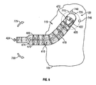
- FIG. 6 is a side view of the moveable device formed in the toy appendage of FIG. 2 .
- FIG. 7 is a perspective view of a portion of an actuator for actuating the moveable device of FIGS. 4-6.
- FIGS. 8 and 9 are side views of the actuator, a portion of which is shown in FIG. 7 .
- a toy 100 has a body 105 and an appendage 110 connected to the body 105 .
- the toy 100 may be of any design, such as, for example, a doll, a plush toy such as a stuffed animal, or a robot.
- the body 105 of the toy 100 may be made of any suitable material.
- the toy is a stuffed animal
- the body 105 may include a rigid internal shell surrounded by a resilient material and covered with a pile that resembles the animal's coat.
- the appendage 110 includes a moveable device 115 that is actuated by an actuator 120 inside the body 105 to move the appendage 110 .
- the actuator 120 is powered by a power source 125 that may or may not be internal to the body 105 .
- the power source 125 may be an electric source that includes a battery.
- the battery is placed in the body 105 and may be turned off and on by a switch accessible on the body 105 .
- the actuator 120 is configured to rotate the moveable device 115 about a drive axis 150 that is fixed relative to the body 105 of the toy 100 . Additionally, the actuator 120 is configured to rotate at least a first portion of the moveable device 115 relative to at least a second portion of the moveable device 115 about a device axis 160 that is fixed relative to the moveable device 115 .
- the first portion of the moveable device 115 may be any portion of the moveable device 115 , such as, for example, portion 165 (shown in FIG. 4 ).
- the second portion of the moveable device 115 may be any portion of the moveable device 115 that includes a portion not included in the first portion, such as, for example, portion 170 (shown in FIG. 5 ).
- the moveable device 115 includes a flexible strip 400 that has a first surface 405 and a second surface 410 .
- the flexible strip 400 may be made of any suitable material that is flexible.
- the strip 400 may be made of a plastic that is either pliable or formed thin enough to bend.
- the moveable device 115 includes at least one plate 415 , at least one of which is transversely connected to the first surface 405 .
- a plate 415 may be formed integrally to the flexible strip 400 during a molding process.
- a plate 415 may be formed separately from the formation of the flexible strip 400 and then attached to the flexible strip 400 using a suitable attachment technique.
- a plate 415 may be glued to the flexible strip 400 .
- a plate 415 may be shaped to fit into a slot formed in the flexible strip 400 and then snap fit into the slot during assembly. At least one of the plates 415 may be detached from the first surface 405 , yet positioned near the first surface 405 .
- the moveable device 115 also includes a first elongated device 420 that intersects at least one of the plates 415 .
- the first elongated device 420 may be made of any flexible material.
- the first elongated device 420 is made of a string that may become slack in the absence of any pulling force.
- the first elongated device 420 is made of a flexible, yet firm material such as a wire strip that may be pulled or pushed to provide tension to the device 420 .
- the first elongated device 420 has a first end 422 (shown in FIG. 6) that is connected to the actuator 120 (portions 122 external to the body 105 are shown in FIGS. 4-6) and a second end 424 that is designed to engage a plate 425 positioned along the first portion 165 of the moveable device 115 , which is at the edge of the flexible strip 400 farthest from the body 105 .
- the first elongated device 420 may be pulled toward the actuator 120 and the second end 424 engages the plate 425 .
- the flexible strip 400 bends and thus the first portion 165 is rotated in a first device direction (for example, in a direction as depicted by arrow 430 in FIG. 4) about the device axis 160 .
- the moveable device 115 may include at least one plate 465 , at least one of which is transversely connected to the second surface 410 .
- the plate 465 may be formed integrally to the flexible strip 400 during a molding process.
- the plate 465 may be formed separately from the formation of the flexible strip 400 and then attached to the flexible strip 400 using a suitable attachment technique.
- the plate 465 may be glued to the flexible strip 400 or shaped to snap fit into a slot formed in the flexible strip 400 .
- At least one of the plates 465 may be detached from the second surface 410 , yet positioned near the second surface 410 .
- the moveable device 115 also may include a second elongated device 470 that intersects at least one of the plates 465 .
- the second elongated device 470 may be made of any flexible material such as string or a wire strip.
- the second elongated device 470 has a first end 472 that is connected to the actuator 120 and a second end 474 that is designed to engage a plate 475 positioned along the first portion 165 of the moveable device 115 , which is at the edge of the flexible strip 400 farthest from the body 105 .
- the second elongated device 470 may be pulled toward the actuator and the second end 474 engages the plate 475 .
- the flexible strip 400 bends and thus the first portion 165 is rotated in a second device direction (for example, in a direction as depicted by arrow 480 in FIG. 5) about the device axis 160 .
- the second device direction is different from the first device direction.
- the plate 465 is offset from the plate 415 along the length of the flexible strip 400 .
- the actuator 120 may be designed with first and second levers 700 , 705 , respectively, that are rotatable about the drive axis 150 .
- the levers 700 , 705 rotate simultaneously upon actuation.
- the actuator 120 includes a base plate 715 that positions the moveable device 115 relative to the levers 700 , 705 .
- the moveable device 115 may be attached to a bottom portion 720 of the base plate 715 using any suitable technique.
- a plate 435 (FIG. 7) may be glued (or otherwise fastened) to the bottom portion 720 .
- the base plate 715 may be formed integrally to the moveable device 115 .
- the base plate 715 is rotatable about the drive axis 150 such that the levers 700 , 705 rotate when the base plate 715 rotates.
- the base plate 715 may include a projection 735 that engages projections 740 , 745 attached to the body 105 to prevent the base plate 715 from rotating beyond positions that correspond to the positions of the projections 740 , 745 .
- the base plate 715 is rotated when the levers 700 , 705 are rotated to effectuate a compound movement of the appendage 110 . If the toy 100 is a stuffed animal, then this compound movement resembles a hugging motion.
- the actuator 120 also includes a rotating device 800 , a rotating drive 805 , and a motor 810 .
- the rotating device 800 is attached to the rotating drive 805 and the rotating drive 805 is integral to the motor 810 .
- the motor 810 when the motor 810 is powered, it rotates the rotating drive 805 , which in turn rotates the rotating device 800 about the drive axis 150 .
- the rotating device 800 has a projection 802 that engages a notch 804 in the lever 700 (as shown), lever 705 (not shown), or a structure to which levers 700 and 705 connect (not shown), to rotate the levers 700 , 705 when the motor 810 turns the rotating drive 805 .
- the levers 700 , 705 and the base plate 715 are secured to the rotating device 800 with any suitable attachment technique.
- the levers 700 , 705 and the base plate 715 may be formed with holes through which a screw 812 passes and the rotating device 800 may be formed with a threaded hole 815 for receiving the screw 812 .
- the motor 810 rotates the moveable device 115 in the first main direction 730 simultaneously with rotation of the first portion relative to the second portion in the first device direction 430 as shown in FIG. 4 .
- the motor 810 rotates the device 800 , which rotates the base plate 715 , which rotates the moveable device 115 that is attached to the base plate 715 about the drive axis 150 in the first main direction 730 .
- the device 800 rotates the first lever 700 , which pulls the first elongated device 420 and engages the plate 425 , causing the first portion 165 to rotate relative to the second portion 170 about the device axis 160 in the first device direction 430 .
- the device 800 may begin to rotate the first lever 700 after the moveable device 115 has finished rotating, for example, after the projection 735 engages projection 740 . In another implementation, the device 800 may begin to rotate the first lever 700 when it begins to rotate the moveable device 115 about the drive axis 150 .
- the second lever 705 is rotated in a direction that reduces the tension on the second elongated device 470 , thus creating a slack in the second elongated device 470 .
- the motor 810 When the motor 810 is reversed, it rotates the moveable device 115 in the second main direction 725 simultaneously with rotation of the first portion relative to the second portion in the second device direction 480 as shown in FIG. 5 .
- the motor 810 rotates the device 800 , which rotates the base plate 715 , which rotates the moveable device 115 that is attached to the base plate 715 about the drive axis 150 in the second main direction 725 .
- the device 800 rotates the second lever 705 , which pulls the second elongated device 470 and engages the plate 475 , causing the first portion 165 to rotate relative to the second portion 170 about the device axis 160 in the second device direction 480 .
- the device 800 may begin to rotate the second lever 705 after the moveable device 115 has finished rotating, for example, after the projection 735 engages projection 745 . In another implementation, the device 800 may begin to rotate the second lever 705 when it begins to rotate the moveable device 115 about the drive axis 150 .
- the first lever 700 is rotated in a direction that reduces the tension on the first elongated device 420 , thus creating a slack in the first elongated device 420 .
- the motor 810 may be used to impart upon the appendage 110 a compound motion defined by directions 430 and 730 or by directions 480 and 725 .
- the power source 125 may be a mechanical source that includes a device that is operated by a user.
- the mechanical source may include a string attached to the body 105 that the user pulls.
- the mechanical source may include a lever attached to the body 105 that the user pulls.
- the mechanical source may include a dial attached to the body 105 that the user rotates.
- the actuator 120 may be configured to function as described above yet implement gears and/or pulley to effectuate the compound motions.
- the actuator 120 may be designed with a single lever 700 for actuating the first elongated device 420 and for moving the flexible strip in the first device direction 430 . If the moveable device 415 includes both plate 415 and plate 465 , then the actuator 120 may be designed such that levers 700 and 705 rotate independently upon actuation.
- the appendage 110 may be any extension from the body 105 of the toy 100 .
- the appendage 110 may be a leg, a hand, or an arm.
- the appendage may be a tail or an elongated neck.
- the toy 100 may be any design, including animals, humans, robots, or machines.
- the plate 465 may be designed to align with the plate 415 along the length of the flexible strip 400 .
- the flexible strip 400 may include one or more dividing plates 1000 positioned along the first or second surfaces 405 , 410 of the flexible strip 400 .
- the dividing plates 1000 are positioned to be transverse to the plates 415 and to the flexible strip 400 . In this way, the dividing plates 100 serve to strengthen the flexible strip 400 and/or prevent the flexible strip 400 from bending excessively or breaking.
- the flexible strip 400 may have a varying thickness such that a thickness of the strip 400 nearest to the body 105 is greater than a thickness of the strip 400 farthest from the body 105 .
- the first elongated device 420 may be actuated by the actuator 120 by being pulled toward the actuator 120 (as discussed) or by being pushed away from the actuator 120 .
Abstract
An apparatus for a moving a toy appendage includes a moveable device within a toy appendage that is attached to a body of a toy and an actuator connected to the moveable device. The actuator is configured to rotate the moveable device about a drive axis that is fixed relative to the body of the toy. The actuator is configured to rotate at least a first portion of the moveable device relative to at least a second portion of the moveable device about a device axis that is fixed relative to the moveable device.
Description
This application relates to actuation of a toy.
Toys that have moving parts are well known. For example, dolls and plush toys such as stuffed animals are made with moveable appendages.
In one general aspect, an apparatus for a moving a toy appendage includes a moveable device within a toy appendage that is attached to a body of a toy and an actuator connected to the moveable device. The actuator is configured to rotate the moveable device about a drive axis that is fixed relative to the body of the toy. The actuator is configured to rotate at least a first portion of the moveable device relative to at least a second portion of the moveable device about a device axis that is fixed relative to the moveable device.
Implementations may include one or more of the following features. For example, the actuator may include a motor, and a drive shaft connected to the motor and to the moveable device. The drive shaft defines the drive axis. The actuator may rotate the moveable device by causing the drive shaft to rotate the moveable device. The actuator may include a lever coupled to the at least first portion of the moveable device. The actuator may rotate the at least first portion of the moveable device relative to the second portion by causing the drive shaft to rotate the lever coupled to the moveable device.
The moveable device may include a flexible strip, a plate positioned in the at least first portion of the moveable device, with the plate being transversely connected to the flexible strip, and an elongated device that intersects the plate. The lever may be connected to the elongated device such that when the drive shaft rotates the lever, the lever actuates the elongated device to exert a tension on the plate, thus rotating the at least first portion of the moveable device relative to the second portion.
The motor may be configured to rotate the at least first portion relative to the at least second portion in a first device direction about the device axis if the drive shaft is rotated in a first main direction about the drive axis. Additionally, the motor may be configured to rotate the at least first portion relative to the at least second portion in a second device direction about the device axis if the drive shaft is rotated in a second main direction about the drive axis.
The at least first portion and the at least second portion may be included in the moveable device.
The main axis may be different from the device axis.
The actuator may be configured to rotate the at least first portion relative to the at least second portion in a first device direction about the device axis if the moveable device is rotated in a first main direction about the drive axis. The actuator may be configured to rotate the at least first portion relative to the at least second portion in a second device direction about the device axis if the moveable device is rotated in a second main direction about the drive axis.
Because of the motion imparted to the moveable device and the toy appendage, the apparatus provides a realistic actuation of a toy appendage.
Other features and advantages will be apparent from the description, the drawings, and the claims.
FIG. 1 is a perspective view of a toy.
FIG. 2 is a perspective view of an appendage attached to the toy of FIG. 1.
FIG. 3 is a block diagram of the toy of FIG. 1.
FIGS. 4, 5, and 10 are perspective views of a moveable device formed in the toy appendage of FIG. 2.
FIG. 6 is a side view of the moveable device formed in the toy appendage of FIG. 2.
FIG. 7 is a perspective view of a portion of an actuator for actuating the moveable device of FIGS. 4-6.
FIGS. 8 and 9 are side views of the actuator, a portion of which is shown in FIG. 7.
Like reference symbols in the various drawings indicate like elements.
Referring to FIGS. 1-3, a toy 100 has a body 105 and an appendage 110 connected to the body 105. The toy 100 may be of any design, such as, for example, a doll, a plush toy such as a stuffed animal, or a robot. The body 105 of the toy 100 may be made of any suitable material. For example, if the toy is a stuffed animal, the body 105 may include a rigid internal shell surrounded by a resilient material and covered with a pile that resembles the animal's coat.
The appendage 110 includes a moveable device 115 that is actuated by an actuator 120 inside the body 105 to move the appendage 110. The actuator 120 is powered by a power source 125 that may or may not be internal to the body 105. In one implementation, the power source 125 may be an electric source that includes a battery. In this implementation, the battery is placed in the body 105 and may be turned off and on by a switch accessible on the body 105.
Referring to FIGS. 4-6, in general, the actuator 120 is configured to rotate the moveable device 115 about a drive axis 150 that is fixed relative to the body 105 of the toy 100. Additionally, the actuator 120 is configured to rotate at least a first portion of the moveable device 115 relative to at least a second portion of the moveable device 115 about a device axis 160 that is fixed relative to the moveable device 115. The first portion of the moveable device 115 may be any portion of the moveable device 115, such as, for example, portion 165 (shown in FIG. 4). The second portion of the moveable device 115 may be any portion of the moveable device 115 that includes a portion not included in the first portion, such as, for example, portion 170 (shown in FIG. 5).
In particular, the moveable device 115 includes a flexible strip 400 that has a first surface 405 and a second surface 410. The flexible strip 400 may be made of any suitable material that is flexible. For example, the strip 400 may be made of a plastic that is either pliable or formed thin enough to bend. Additionally, the moveable device 115 includes at least one plate 415, at least one of which is transversely connected to the first surface 405. A plate 415 may be formed integrally to the flexible strip 400 during a molding process. Alternatively, a plate 415 may be formed separately from the formation of the flexible strip 400 and then attached to the flexible strip 400 using a suitable attachment technique. For example, a plate 415 may be glued to the flexible strip 400. As another example, a plate 415 may be shaped to fit into a slot formed in the flexible strip 400 and then snap fit into the slot during assembly. At least one of the plates 415 may be detached from the first surface 405, yet positioned near the first surface 405.
The moveable device 115 also includes a first elongated device 420 that intersects at least one of the plates 415. The first elongated device 420 may be made of any flexible material. In one implementation, the first elongated device 420 is made of a string that may become slack in the absence of any pulling force. In another implementation, the first elongated device 420 is made of a flexible, yet firm material such as a wire strip that may be pulled or pushed to provide tension to the device 420.
The first elongated device 420 has a first end 422 (shown in FIG. 6) that is connected to the actuator 120 (portions 122 external to the body 105 are shown in FIGS. 4-6) and a second end 424 that is designed to engage a plate 425 positioned along the first portion 165 of the moveable device 115, which is at the edge of the flexible strip 400 farthest from the body 105. In this way, when the first elongated device 420 is actuated by the actuator 120, the first elongated device 420 may be pulled toward the actuator 120 and the second end 424 engages the plate 425. Upon engagement of the plate 425, the flexible strip 400 bends and thus the first portion 165 is rotated in a first device direction (for example, in a direction as depicted by arrow 430 in FIG. 4) about the device axis 160.
The moveable device 115 may include at least one plate 465, at least one of which is transversely connected to the second surface 410. Like plate 415, the plate 465 may be formed integrally to the flexible strip 400 during a molding process. Alternatively, the plate 465 may be formed separately from the formation of the flexible strip 400 and then attached to the flexible strip 400 using a suitable attachment technique. For example, the plate 465 may be glued to the flexible strip 400 or shaped to snap fit into a slot formed in the flexible strip 400. At least one of the plates 465 may be detached from the second surface 410, yet positioned near the second surface 410.
The moveable device 115 also may include a second elongated device 470 that intersects at least one of the plates 465. Like the first elongated device 420, the second elongated device 470 may be made of any flexible material such as string or a wire strip.
The second elongated device 470 has a first end 472 that is connected to the actuator 120 and a second end 474 that is designed to engage a plate 475 positioned along the first portion 165 of the moveable device 115, which is at the edge of the flexible strip 400 farthest from the body 105. In this way, when the second elongated device 470 is actuated by the actuator 120, the second elongated device 470 may be pulled toward the actuator and the second end 474 engages the plate 475. Upon engagement of the plate 475, the flexible strip 400 bends and thus the first portion 165 is rotated in a second device direction (for example, in a direction as depicted by arrow 480 in FIG. 5) about the device axis 160. The second device direction is different from the first device direction.
As shown, the plate 465 is offset from the plate 415 along the length of the flexible strip 400.
Referring also to FIG. 7, the actuator 120 may be designed with first and second levers 700, 705, respectively, that are rotatable about the drive axis 150. The levers 700, 705 rotate simultaneously upon actuation. The actuator 120 includes a base plate 715 that positions the moveable device 115 relative to the levers 700, 705. The moveable device 115 may be attached to a bottom portion 720 of the base plate 715 using any suitable technique. For example, a plate 435 (FIG. 7) may be glued (or otherwise fastened) to the bottom portion 720. As another example, the base plate 715 may be formed integrally to the moveable device 115.
The base plate 715 is rotatable about the drive axis 150 such that the levers 700, 705 rotate when the base plate 715 rotates. The base plate 715 may include a projection 735 that engages projections 740, 745 attached to the body 105 to prevent the base plate 715 from rotating beyond positions that correspond to the positions of the projections 740, 745.
The base plate 715 is rotated when the levers 700, 705 are rotated to effectuate a compound movement of the appendage 110. If the toy 100 is a stuffed animal, then this compound movement resembles a hugging motion.
Referring to FIGS. 8 and 9, the actuator 120 also includes a rotating device 800, a rotating drive 805, and a motor 810. The rotating device 800 is attached to the rotating drive 805 and the rotating drive 805 is integral to the motor 810. Thus, when the motor 810 is powered, it rotates the rotating drive 805, which in turn rotates the rotating device 800 about the drive axis 150. The rotating device 800 has a projection 802 that engages a notch 804 in the lever 700 (as shown), lever 705 (not shown), or a structure to which levers 700 and 705 connect (not shown), to rotate the levers 700, 705 when the motor 810 turns the rotating drive 805. The levers 700, 705 and the base plate 715 are secured to the rotating device 800 with any suitable attachment technique. For example, as shown, the levers 700, 705 and the base plate 715 may be formed with holes through which a screw 812 passes and the rotating device 800 may be formed with a threaded hole 815 for receiving the screw 812.
During operation, the motor 810 rotates the moveable device 115 in the first main direction 730 simultaneously with rotation of the first portion relative to the second portion in the first device direction 430 as shown in FIG. 4. In particular, the motor 810 rotates the device 800, which rotates the base plate 715, which rotates the moveable device 115 that is attached to the base plate 715 about the drive axis 150 in the first main direction 730. At some point during rotation of the moveable device 115, the device 800 rotates the first lever 700, which pulls the first elongated device 420 and engages the plate 425, causing the first portion 165 to rotate relative to the second portion 170 about the device axis 160 in the first device direction 430.
The device 800 may begin to rotate the first lever 700 after the moveable device 115 has finished rotating, for example, after the projection 735 engages projection 740. In another implementation, the device 800 may begin to rotate the first lever 700 when it begins to rotate the moveable device 115 about the drive axis 150.
During rotation of the lever 700, the second lever 705 is rotated in a direction that reduces the tension on the second elongated device 470, thus creating a slack in the second elongated device 470.
When the motor 810 is reversed, it rotates the moveable device 115 in the second main direction 725 simultaneously with rotation of the first portion relative to the second portion in the second device direction 480 as shown in FIG. 5. In particular, the motor 810 rotates the device 800, which rotates the base plate 715, which rotates the moveable device 115 that is attached to the base plate 715 about the drive axis 150 in the second main direction 725. At some point during rotation of the moveable device 115, the device 800 rotates the second lever 705, which pulls the second elongated device 470 and engages the plate 475, causing the first portion 165 to rotate relative to the second portion 170 about the device axis 160 in the second device direction 480.
The device 800 may begin to rotate the second lever 705 after the moveable device 115 has finished rotating, for example, after the projection 735 engages projection 745. In another implementation, the device 800 may begin to rotate the second lever 705 when it begins to rotate the moveable device 115 about the drive axis 150.
During rotation of the second lever 705, the first lever 700 is rotated in a direction that reduces the tension on the first elongated device 420, thus creating a slack in the first elongated device 420.
In this way, the motor 810 may be used to impart upon the appendage 110 a compound motion defined by directions 430 and 730 or by directions 480 and 725.
Other implementations are within the scope of the following claims. For example, in another implementation, the power source 125 may be a mechanical source that includes a device that is operated by a user. For example, the mechanical source may include a string attached to the body 105 that the user pulls. As another example, the mechanical source may include a lever attached to the body 105 that the user pulls. As a further example, the mechanical source may include a dial attached to the body 105 that the user rotates.
The actuator 120 may be configured to function as described above yet implement gears and/or pulley to effectuate the compound motions.
In another implementation, if the moveable device 415 does not include plate 465, the actuator 120 may be designed with a single lever 700 for actuating the first elongated device 420 and for moving the flexible strip in the first device direction 430. If the moveable device 415 includes both plate 415 and plate 465, then the actuator 120 may be designed such that levers 700 and 705 rotate independently upon actuation.
The appendage 110 may be any extension from the body 105 of the toy 100. For example, the appendage 110 may be a leg, a hand, or an arm. As another example, the appendage may be a tail or an elongated neck. The toy 100 may be any design, including animals, humans, robots, or machines.
The plate 465 may be designed to align with the plate 415 along the length of the flexible strip 400.
The flexible strip 400 may include one or more dividing plates 1000 positioned along the first or second surfaces 405, 410 of the flexible strip 400. The dividing plates 1000 are positioned to be transverse to the plates 415 and to the flexible strip 400. In this way, the dividing plates 100 serve to strengthen the flexible strip 400 and/or prevent the flexible strip 400 from bending excessively or breaking.
To facilitate relative movement between the first portion 165 and the second portion 170, the flexible strip 400 may have a varying thickness such that a thickness of the strip 400 nearest to the body 105 is greater than a thickness of the strip 400 farthest from the body 105.
In another implementation, if the first elongated device 420 is made of the flexible yet firm material, then the first elongated device 420 may be actuated by the actuator 120 by being pulled toward the actuator 120 (as discussed) or by being pushed away from the actuator 120.
Claims (23)
1. An apparatus for moving a toy appendage, the apparatus comprising:
a moveable device within a toy appendage that is attached to a body of a toy, the moveable device including an elongated device extending from the toy body; and
an actuator including a lever mounted to a drive shaft that rotates about a drive axis, the drive axis being fixed relative to the toy body, the lever connected to the elongated device of the moveable device to rotate the moveable device about the drive axis and to rotate at least a first portion of the moveable device relative to at least a second portion of the moveable device about a device axis that is fixed relative to the moveable device as the drive shaft rotates the lever about the drive axis.
2. The apparatus of claim 1 in which the actuator comprises
a motor;
wherein the drive shaft is connected to the motor and to the lever, the drive shaft defining the drive axis.
3. The apparatus of claim 1 in which the lever is coupled to the at least first portion of the moveable device.
4. The apparatus of claim 1 in which the moveable device comprises:
a flexible strip;
a plate positioned in the at least first portion of the moveable device, with the plate being transversely connected to the flexible strip; and
an elongated device that intersects the plate.
5. The apparatus of claim 4 in which the lever is connected to the elongated device such that when the drive shaft rotates the lever, the lever actuates the elongated device to exert a tension on the plate, thus rotating the at least first portion of the moveable device relative to the second portion.
6. The apparatus of claim 1 in which the motor is configured to rotate the at least first portion relative to the at least second portion in a first device direction about the device axis if the drive shaft is rotated in a first main direction about the drive axis.
7. The apparatus of claim 6 in which the motor is configured to rotate the at least first portion relative to the at least second portion in a second device direction about the device axis if the drive shaft is rotated in a second main direction about the drive axis;
in which the second device direction is opposite to the first device direction and the second main direction is opposite to the second device direction.
8. The apparatus of claim 1 in which the at least first portion and the at least second portion are included in the moveable device.
9. The apparatus of claim 1 in which the drive axis is different from the device axis.
10. The apparatus of claim 1 in which the actuator is configured to:
rotate the at least first portion relative to the at least second portion in a first device direction about the device axis if the moveable device is rotated in a first main direction about the drive axis; and
rotate the at least first portion relative to the at least second portion in a second device direction about the device axis if the moveable device is rotated in a second main direction about the drive axis.
11. A method of actuating an appendage attached to a body of a toy, the method comprising:
rotating a lever mounted to a drive shaft about a drive axis that is fixed relative to the body of the toy, the lever being connected to an elongated device that extends along the appendage;
in which rotation of the lever causes the appendage to rotate about the drive axis and causes at least a first portion of the appendage to rotate relative to at least a second portion of the appendage about a device axis that is fixed relative to the appendage.
12. The method of claim 11 in which rotating the lever comprises causing a drive shaft connected to a motor to rotate the lever, the drive shaft defining the drive axis.
13. The method of claim 11 in which rotating the at least first portion of the appendage relative to the at least second portion of the appendage comprises coupling the lever to the at least first portion of the appendage.
14. The method of claim 11 in which rotating the appendage about the drive axis occurs before rotating the at least first portion relative to the at least second portion.
15. The method of claim 11 in which rotating the appendage about the drive axis occurs simultaneously with rotating the at least first portion relative to the at least second portion.
16. An apparatus for a moving a toy appendage, the apparatus comprising:
a moveable device within a toy appendage that is attached to a body of a toy, the moveable device including:
a flexible strip,
a plate transversely connected to the flexible strip and positioned within a first portion of the moveable device, and
an elongated device that intersects the plate; and
an actuator coupled to the moveable device to rotate the moveable device about a drive axis, the actuator coupled to the at least first portion of the moveable device to rotate the at least first portion of the moveable device relative to at least a second portion of the moveable device about a device axis that is fixed relative to the moveable device.
17. The apparatus of claim 16 in which the lever is connected to the elongated device such that when the lever is rotated, the lever actuates the elongated device to exert tension on the plate, thus rotating the at least first portion of the moveable device relative to the second portion.
18. An apparatus for moving an appendage of a toy, the apparatus comprising:
a moveable device within a toy appendage that is attached to a body of the toy; and
an actuator including a motor having a drive shaft configured to rotate about a drive axis and being connected to the moveable device such that as the drive shaft rotates about the drive axis, the actuator causes the moveable device to rotate about an axis that is parallel with the drive axis and causes at least a first portion of the moveable device to rotate relative to at least a second portion of the moveable device about a device axis that is fixed relative to the moveable device.
19. The apparatus of claim 18 in which the actuator causes the moveable device to rotate about the drive axis.
20. The apparatus of claim 18 in which the drive axis is fixed relative to the body of the toy.
21. An apparatus for moving an appendage of a toy, the apparatus comprising:
a moveable device within a toy appendage of the toy; and
an actuation system coupled to a motor and to the moveable device, the actuation system being constrained to rotate about a single drive axis such that the actuation system causes the moveable device to rotate about an axis that is parallel with the drive axis and causes at least a first portion of the moveable device to rotate relative to at least a second portion of the moveable device about a device axis that is fixed relative to the moveable device.
22. The apparatus of claim 21 in which the drive axis is different from the device axis.
23. The apparatus of claim 21 in which the drive axis is fixed relative to the body of the toy.
Priority Applications (5)
| Application Number | Priority Date | Filing Date | Title |
|---|---|---|---|
| US10/073,122 US6773327B1 (en) | 2002-02-12 | 2002-02-12 | Apparatus for actuating a toy |
| US10/667,977 US7066782B1 (en) | 2002-02-12 | 2003-09-23 | Electromechanical toy |
| US10/837,570 US7507139B1 (en) | 2002-02-12 | 2004-05-04 | Electromechanical toy |
| US10/897,425 US7416468B1 (en) | 2002-02-12 | 2004-07-23 | Apparatus for actuating a toy |
| US11/380,384 US7431629B1 (en) | 2002-02-12 | 2006-04-26 | Electromechanical toy |
Applications Claiming Priority (1)
| Application Number | Priority Date | Filing Date | Title |
|---|---|---|---|
| US10/073,122 US6773327B1 (en) | 2002-02-12 | 2002-02-12 | Apparatus for actuating a toy |
Related Child Applications (2)
| Application Number | Title | Priority Date | Filing Date |
|---|---|---|---|
| US10/305,265 Continuation-In-Part US7695341B1 (en) | 2002-02-12 | 2002-11-27 | Electromechanical toy |
| US10/897,425 Continuation US7416468B1 (en) | 2002-02-12 | 2004-07-23 | Apparatus for actuating a toy |
Publications (1)
| Publication Number | Publication Date |
|---|---|
| US6773327B1 true US6773327B1 (en) | 2004-08-10 |
Family
ID=32823209
Family Applications (5)
| Application Number | Title | Priority Date | Filing Date |
|---|---|---|---|
| US10/073,122 Expired - Lifetime US6773327B1 (en) | 2002-02-12 | 2002-02-12 | Apparatus for actuating a toy |
| US10/667,977 Expired - Lifetime US7066782B1 (en) | 2002-02-12 | 2003-09-23 | Electromechanical toy |
| US10/837,570 Expired - Fee Related US7507139B1 (en) | 2002-02-12 | 2004-05-04 | Electromechanical toy |
| US10/897,425 Expired - Lifetime US7416468B1 (en) | 2002-02-12 | 2004-07-23 | Apparatus for actuating a toy |
| US11/380,384 Expired - Lifetime US7431629B1 (en) | 2002-02-12 | 2006-04-26 | Electromechanical toy |
Family Applications After (4)
| Application Number | Title | Priority Date | Filing Date |
|---|---|---|---|
| US10/667,977 Expired - Lifetime US7066782B1 (en) | 2002-02-12 | 2003-09-23 | Electromechanical toy |
| US10/837,570 Expired - Fee Related US7507139B1 (en) | 2002-02-12 | 2004-05-04 | Electromechanical toy |
| US10/897,425 Expired - Lifetime US7416468B1 (en) | 2002-02-12 | 2004-07-23 | Apparatus for actuating a toy |
| US11/380,384 Expired - Lifetime US7431629B1 (en) | 2002-02-12 | 2006-04-26 | Electromechanical toy |
Country Status (1)
| Country | Link |
|---|---|
| US (5) | US6773327B1 (en) |
Cited By (49)
| Publication number | Priority date | Publication date | Assignee | Title |
|---|---|---|---|---|
| US20050041048A1 (en) * | 2001-11-08 | 2005-02-24 | Hillman Michael D. | Computer controlled display device |
| US20050251112A1 (en) * | 2003-05-23 | 2005-11-10 | Danitz David J | Articulating mechanism for remote manipulation of a surgical or diagnostic tool |
| US20050273084A1 (en) * | 2004-06-07 | 2005-12-08 | Novare Surgical Systems, Inc. | Link systems and articulation mechanisms for remote manipulation of surgical or diagnostic tools |
| US20050273085A1 (en) * | 2004-06-07 | 2005-12-08 | Novare Surgical Systems, Inc. | Articulating mechanism with flex-hinged links |
| US20060111615A1 (en) * | 2004-11-23 | 2006-05-25 | Novare Surgical Systems, Inc. | Articulating sheath for flexible instruments |
| US20060111209A1 (en) * | 2004-11-23 | 2006-05-25 | Novare Surgical Systems, Inc. | Articulating mechanisms and link systems with torque transmission in remote manipulation of instruments and tools |
| US20060111616A1 (en) * | 2004-11-24 | 2006-05-25 | Novare Surgical Systems, Inc. | Articulating mechanism components and system for easy assembly and disassembly |
| US20060156851A1 (en) * | 2004-12-02 | 2006-07-20 | Jacobsen Stephen C | Mechanical serpentine device |
| US20070250113A1 (en) * | 2003-05-23 | 2007-10-25 | Hegeman David E | Tool with articulation lock |
| US20070254556A1 (en) * | 2006-04-26 | 2007-11-01 | Mga Entertainment, Inc. | Curling structure for a simulated aquatic creature and the like |
| US20070287993A1 (en) * | 2006-06-13 | 2007-12-13 | Hinman Cameron D | Tool with rotation lock |
| US20080136254A1 (en) * | 2006-11-13 | 2008-06-12 | Jacobsen Stephen C | Versatile endless track for lightweight mobile robots |
| US20080255421A1 (en) * | 2007-04-16 | 2008-10-16 | David Elias Hegeman | Articulating tool with improved tension member system |
| US20080255608A1 (en) * | 2007-04-16 | 2008-10-16 | Hinman Cameron D | Tool with end effector force limiter |
| US20080255588A1 (en) * | 2007-04-16 | 2008-10-16 | Hinman Cameron D | Tool with multi-state ratcheted end effector |
| US20080262538A1 (en) * | 2003-05-23 | 2008-10-23 | Novare Surgical Systems, Inc. | Articulating instrument |
| US7517271B1 (en) * | 2005-10-12 | 2009-04-14 | Albert Alfaro | Control system for a puppet |
| US20100003889A1 (en) * | 2008-07-07 | 2010-01-07 | G2 Inventions | Flexible mechanical appendage |
| US20100041945A1 (en) * | 2008-08-18 | 2010-02-18 | Isbell Jr Lewis | Instrument with articulation lock |
| US8002716B2 (en) | 2007-05-07 | 2011-08-23 | Raytheon Company | Method for manufacturing a complex structure |
| US8002365B2 (en) | 2006-11-13 | 2011-08-23 | Raytheon Company | Conformable track assembly for a robotic crawler |
| US20110282149A1 (en) * | 2002-09-12 | 2011-11-17 | Intuitive Surgical Operations, Inc. | Shape-transferring cannula system and method of use |
| US8185241B2 (en) | 2006-11-13 | 2012-05-22 | Raytheon Company | Tracked robotic crawler having a moveable arm |
| US8317555B2 (en) | 2009-06-11 | 2012-11-27 | Raytheon Company | Amphibious robotic crawler |
| DE102012106595A1 (en) | 2011-07-20 | 2013-01-24 | Mattel, Inc. | Flexible toy figure with armature |
| US8392036B2 (en) | 2009-01-08 | 2013-03-05 | Raytheon Company | Point and go navigation system and method |
| US8393422B1 (en) | 2012-05-25 | 2013-03-12 | Raytheon Company | Serpentine robotic crawler |
| US8571711B2 (en) | 2007-07-10 | 2013-10-29 | Raytheon Company | Modular robotic crawler |
| US8935014B2 (en) | 2009-06-11 | 2015-01-13 | Sarcos, Lc | Method and system for deploying a surveillance network |
| US20150122073A1 (en) * | 2012-06-01 | 2015-05-07 | Aldebaran Robotics | Spinal column for a humanoid robot |
| US9031698B2 (en) | 2012-10-31 | 2015-05-12 | Sarcos Lc | Serpentine robotic crawler |
| US20150174500A1 (en) * | 2012-03-30 | 2015-06-25 | Philip Michael Peter Beglan | Transformable Cable Volume Structure |
| US9161771B2 (en) | 2011-05-13 | 2015-10-20 | Intuitive Surgical Operations Inc. | Medical instrument with snake wrist structure |
| US9221179B2 (en) | 2009-07-23 | 2015-12-29 | Intuitive Surgical Operations, Inc. | Articulating mechanism |
| US9409292B2 (en) | 2013-09-13 | 2016-08-09 | Sarcos Lc | Serpentine robotic crawler for performing dexterous operations |
| US9566711B2 (en) | 2014-03-04 | 2017-02-14 | Sarcos Lc | Coordinated robotic control |
| US20170162088A1 (en) * | 2014-03-24 | 2017-06-08 | Speecys Corp. | Figure, base, and figure system |
| US10071303B2 (en) | 2015-08-26 | 2018-09-11 | Malibu Innovations, LLC | Mobilized cooler device with fork hanger assembly |
| US10143362B2 (en) | 2002-09-12 | 2018-12-04 | Intuitive Surgical Operations, Inc. | Shape-transferring cannula system and method of use |
| US10213919B2 (en) * | 2015-03-23 | 2019-02-26 | Rolls-Royce Plc | Flexible tools and apparatus for machining objects |
| US10245517B2 (en) | 2017-03-27 | 2019-04-02 | Pacific Cycle, Llc | Interactive ride-on toy apparatus |
| US20190366536A1 (en) * | 2018-05-29 | 2019-12-05 | General Electric Company | Robotic Arm Assembly Construction |
| US10695684B1 (en) * | 2019-07-01 | 2020-06-30 | Spin Master Ltd. | Articulating object |
| US10807659B2 (en) | 2016-05-27 | 2020-10-20 | Joseph L. Pikulski | Motorized platforms |
| US11020679B1 (en) * | 2018-11-27 | 2021-06-01 | Rory T Sledge | Rotating flipping and grasping movements in mechanical toys |
| USD921128S1 (en) | 2019-10-15 | 2021-06-01 | Spin Master Ltd. | Animal figure |
| USD921129S1 (en) | 2019-10-15 | 2021-06-01 | Spin Master Ltd. | Animal figure |
| US11103800B1 (en) | 2017-02-17 | 2021-08-31 | Hasbro, Inc. | Toy robot with programmable and movable appendages |
| KR20210131003A (en) * | 2020-04-23 | 2021-11-02 | (주)메세 | Motion puppet |
Families Citing this family (20)
| Publication number | Priority date | Publication date | Assignee | Title |
|---|---|---|---|---|
| US7238079B2 (en) * | 2003-01-14 | 2007-07-03 | Disney Enterprise, Inc. | Animatronic supported walking system |
| GB2398394B (en) * | 2003-02-14 | 2006-05-17 | Dyson Ltd | An autonomous machine |
| US20060228982A1 (en) * | 2005-04-12 | 2006-10-12 | Rehco, Llc | Interactive figure |
| US7551523B2 (en) * | 2007-02-08 | 2009-06-23 | Isaac Larian | Animated character alarm clock |
| US20090023358A1 (en) * | 2007-07-17 | 2009-01-22 | Triple One Co., Ltd | Interactive toy control system |
| CN101406755A (en) * | 2007-10-12 | 2009-04-15 | 鹏智科技(深圳)有限公司 | Human-shaped interactive toy |
| CN101411946B (en) * | 2007-10-19 | 2012-03-28 | 鸿富锦精密工业(深圳)有限公司 | Toy dinosaur |
| US20090156091A1 (en) * | 2007-12-12 | 2009-06-18 | Barnet Mankes | Animatronic figurine |
| US8057275B2 (en) * | 2008-09-23 | 2011-11-15 | Hasbro, Inc. | Toy with pivoting portions capable of rolling over and methods thereof |
| US8662955B1 (en) | 2009-10-09 | 2014-03-04 | Mattel, Inc. | Toy figures having multiple cam-actuated moving parts |
| US8188390B1 (en) | 2010-03-24 | 2012-05-29 | Hasbro, Inc. | Electromechanical toy with momentary actuator dual purpose cam mechanism preserving battery life |
| US8784154B2 (en) | 2010-11-23 | 2014-07-22 | Mattel, Inc. | Toy figure with reciprocally movable limb |
| TW201325681A (en) * | 2011-12-26 | 2013-07-01 | Sap Link Technology Corp | Interactive electronic toy |
| US8997697B1 (en) * | 2012-07-09 | 2015-04-07 | Perry L. Dailey | Agricultural security assembly |
| US9586156B2 (en) | 2013-07-02 | 2017-03-07 | Hasbro, Inc. | Bidirectional gear assembly for electromechanical toys |
| AU2016250773A1 (en) | 2015-04-23 | 2017-10-12 | Hasbro, Inc. | Context-aware digital play |
| JP6600707B2 (en) * | 2018-02-26 | 2019-10-30 | 株式会社タカラトミー | Shape change toy |
| JP6637530B2 (en) * | 2018-02-26 | 2020-01-29 | 株式会社タカラトミー | Shape change toys |
| WO2020235709A1 (en) * | 2019-05-21 | 2020-11-26 | 엘지전자 주식회사 | Action robot |
| WO2020251098A1 (en) * | 2019-06-14 | 2020-12-17 | 엘지전자 주식회사 | Robot |
Citations (26)
| Publication number | Priority date | Publication date | Assignee | Title |
|---|---|---|---|---|
| US2194537A (en) * | 1939-04-03 | 1940-03-26 | Harry D Adams | Toy |
| US2421279A (en) * | 1943-03-25 | 1947-05-27 | Emanuel Merian | Body with movable parts |
| US2614365A (en) | 1949-07-25 | 1952-10-21 | Musselwhite Yolanda Helen | Doll with movable arms |
| US3266059A (en) * | 1963-06-19 | 1966-08-16 | North American Aviation Inc | Prestressed flexible joint for mechanical arms and the like |
| US4494417A (en) * | 1979-03-16 | 1985-01-22 | Robotgruppen Hb | Flexible arm, particularly a robot arm |
| US4516951A (en) | 1982-11-29 | 1985-05-14 | Iwaya Corporation | Movable toy animal |
| US4571208A (en) * | 1983-08-25 | 1986-02-18 | Iwaya Corporation | Toy with swing |
| US4601671A (en) | 1985-05-14 | 1986-07-22 | Demars Robert | Huggable toy mechanism |
| US4802878A (en) * | 1987-02-06 | 1989-02-07 | Marvin Glass & Associates | Doll with rotating and bendable arms |
| US4815911A (en) * | 1982-07-05 | 1989-03-28 | Komatsu, Ltd. | Device for torsion-proof connection of an element in a robot arm or the like |
| GB2221401A (en) * | 1988-07-30 | 1990-02-07 | Takara Co Ltd | Movable decorative assembly |
| GB2222959A (en) * | 1988-09-16 | 1990-03-28 | Takara Co Ltd | Movable decorative article |
| US4968280A (en) | 1989-09-29 | 1990-11-06 | Mattel, Inc. | Animated figure with interactive head and torso |
| US5080682A (en) * | 1990-07-05 | 1992-01-14 | Schectman Leonard A | Artificial robotic hand |
| US5080681A (en) * | 1990-09-10 | 1992-01-14 | Calspan Corporation | Hand with conformable grasp |
| US5297443A (en) * | 1992-07-07 | 1994-03-29 | Wentz John D | Flexible positioning appendage |
| US5324225A (en) | 1990-12-11 | 1994-06-28 | Takara Co., Ltd. | Interactive toy figure with sound-activated and pressure-activated switches |
| US5378188A (en) | 1993-10-08 | 1995-01-03 | Clark; Dolores H. | Tendon and spring for toy actuation |
| US5409447A (en) * | 1993-10-07 | 1995-04-25 | Wedge, Jr.; Roy D. | Orthopedic assembly device to functionally assist a disable human hand |
| DE19755465A1 (en) * | 1997-12-03 | 1999-06-17 | Alexander Dechert | Cable operated artificial hand |
| US5931715A (en) | 1997-12-11 | 1999-08-03 | Chang; Chin-Der | Swinging mechanism for a toy to simulate tail movement of an aquatic animal |
| JPH11207042A (en) * | 1998-01-26 | 1999-08-03 | Agency Of Ind Science & Technol | Artificial arm |
| US6200190B1 (en) | 1996-12-23 | 2001-03-13 | Thomas K Reynolds | Hugging mechanism |
| JP2001300149A (en) * | 2000-04-20 | 2001-10-30 | Moritoshi Kondou | Moving toy |
| US6371826B1 (en) | 2000-08-04 | 2002-04-16 | Mattel, Inc. | Plush animal figure having moving ears and nose |
| US6458010B1 (en) * | 1999-02-19 | 2002-10-01 | Sony Corporation | Curving mechanism and robot |
Family Cites Families (124)
| Publication number | Priority date | Publication date | Assignee | Title |
|---|---|---|---|---|
| US112550A (en) | 1871-03-14 | Improvement in creeping dolls | ||
| US1345052A (en) * | 1919-10-27 | 1920-06-29 | Davis S Williams | Jointed figure |
| US1574035A (en) * | 1922-04-03 | 1926-02-23 | Max E Bernhardt | Toy |
| US1601983A (en) * | 1926-01-02 | 1926-10-05 | Edward S Savage | Toy |
| US1639442A (en) | 1926-02-01 | 1927-08-16 | Ferdinand Strauss Corp | Tail-wiggling toy |
| US1891816A (en) * | 1932-03-05 | 1932-12-20 | All Fair Inc | Figure toy |
| US1992477A (en) | 1934-05-02 | 1935-02-26 | Domowitch George | Mechanical walking doll |
| US2158860A (en) * | 1936-08-28 | 1939-05-16 | Herman S Hyde | Mechanical movement for toy figures and so forth |
| US2232615A (en) * | 1940-11-02 | 1941-02-18 | Kupka Edward Frank | Toy |
| US2641865A (en) * | 1947-04-08 | 1953-06-16 | Gowland John Pinkney | Toy locomotive |
| US2663964A (en) * | 1947-10-13 | 1953-12-29 | W D Burger | Artificial fishing bait |
| US2606022A (en) | 1948-05-18 | 1952-08-05 | Nat Pneumatic Co Inc | Door operation and control |
| US2620594A (en) | 1949-09-06 | 1952-12-09 | Parisi Frank | Musical dozing animal toy |
| US2596216A (en) * | 1950-06-16 | 1952-05-13 | Clifford F Dawson | Worm simulating toy |
| US2800323A (en) | 1951-10-02 | 1957-07-23 | Pittsburgh Plate Glass Co | Door-operating system |
| US2782032A (en) | 1954-05-24 | 1957-02-19 | Ralph B Plympton | Hobby horses |
| US2738617A (en) * | 1954-07-29 | 1956-03-20 | Gary Starling C | Articulated undulating and crawling toy |
| US2801104A (en) | 1955-05-03 | 1957-07-30 | Lloyd E Yetter | Coin controlled mechanical animal |
| US2910799A (en) * | 1957-09-04 | 1959-11-03 | Gerald G Wentworth | Articulated fishing lure |
| US3164924A (en) * | 1961-08-23 | 1965-01-12 | Marx & Co Louis | Animated figure toy |
| US3163960A (en) * | 1962-02-28 | 1965-01-05 | Marx & Co Louis | Walking toy figure |
| US3199248A (en) | 1962-05-18 | 1965-08-10 | Marx & Co Louis | Animated talking toy with built-in recorder |
| US3181270A (en) * | 1963-04-23 | 1965-05-04 | Trevena Charles Dale | Movable wheeled inch worm toy |
| US3395483A (en) * | 1965-07-28 | 1968-08-06 | Thomas R. Mullins | Crawling toy |
| US3490172A (en) * | 1967-03-03 | 1970-01-20 | Arthur Schwartz | Electrically operated toy worm |
| US3484988A (en) | 1967-05-22 | 1969-12-23 | Saul Robbins | Walking doll with ambulatory traction-drive mechanism |
| GB1229688A (en) * | 1968-09-12 | 1971-04-28 | ||
| AT331694B (en) | 1970-04-21 | 1976-08-25 | Helmut Darda | SPRING DRIVE FOR VEHICLE TOYS |
| US3641702A (en) * | 1970-05-04 | 1972-02-15 | Mattel Inc | Doll with leg kick action |
| US3940879A (en) | 1970-12-14 | 1976-03-02 | Glass Marvin I | Walking doll |
| US3705387A (en) * | 1971-01-11 | 1972-12-05 | Kenneth Stern | Remote control system for electro-mechanical vehicle |
| US3994092A (en) * | 1975-12-05 | 1976-11-30 | Mattel, Inc. | Figure toy having reverse gear ratio between limbs |
| US4086724A (en) | 1976-01-16 | 1978-05-02 | Mccaslin Robert E | Motorized toy vehicle having improved control means |
| JPS551664Y2 (en) * | 1976-07-22 | 1980-01-17 | ||
| US4165581A (en) | 1976-10-27 | 1979-08-28 | Tobin Wolf | Sound controlled vehicle |
| US4079938A (en) | 1976-12-06 | 1978-03-21 | Ideal Toy Corporation | Toy vehicle and toy vehicle game |
| US4125261A (en) | 1977-04-01 | 1978-11-14 | Ideal Toy Corporation | Toy vehicle and toy vehicle game |
| JPS54163132A (en) | 1978-06-15 | 1979-12-25 | Hiroisa Iwatani | Power switch for moving toy |
| JPS5631271Y2 (en) | 1978-07-01 | 1981-07-24 | ||
| US4248012A (en) | 1978-12-26 | 1981-02-03 | Kirby James S | Lane changing car |
| US4276717A (en) | 1979-01-19 | 1981-07-07 | Aurora Products Canada, Ltd. | Periodically swerving toy vehicle |
| US4224759A (en) | 1979-02-16 | 1980-09-30 | Mattel, Inc. | Animated pull toy |
| US4231183A (en) | 1979-06-22 | 1980-11-04 | Ideal Toy Corporation | Differential gear drive |
| US4333261A (en) | 1980-01-22 | 1982-06-08 | California R & D Center | Two speed toy car and track assembly |
| JPS6130703Y2 (en) | 1980-11-19 | 1986-09-08 | ||
| GB2102685B (en) | 1981-07-27 | 1984-02-01 | Refined Ind Co Ltd | Slotless racing cars |
| EP0098851B1 (en) | 1982-01-19 | 1985-09-25 | Joustra S.A. | Electric motor toy vehicle |
| JPS598392U (en) | 1982-07-10 | 1984-01-19 | ミツワ工業株式会社 | Toy car with winch mechanism |
| JPS59133297U (en) * | 1983-02-26 | 1984-09-06 | 株式会社トミー | Swing walking animal toy |
| US4540176A (en) | 1983-08-25 | 1985-09-10 | Sanders Associates, Inc. | Microprocessor interface device |
| JPS6055985A (en) | 1983-09-05 | 1985-04-01 | 株式会社トミー | Sound recognizing toy |
| JPS60253483A (en) | 1984-05-28 | 1985-12-14 | イワヤ株式会社 | Animal play toy |
| US4573941A (en) * | 1984-08-23 | 1986-03-04 | Buddy L Corp. | Steerable toy vehicle |
| US4671779A (en) * | 1984-09-07 | 1987-06-09 | Kabushiki Kaisha Gakushu Kenkyusha | Running toy |
| US4673371A (en) | 1985-04-26 | 1987-06-16 | Tomy Kogyo Co., Inc. | Robot-like toy vehicle |
| US4662854A (en) | 1985-07-12 | 1987-05-05 | Union Electric Corp. | Self-propellable toy and arrangement for and method of controlling the movement thereof |
| US4655724A (en) | 1985-12-27 | 1987-04-07 | Soma International Ltd. | Toy vehicle and steering and drive mechanism therefor |
| DE3615986A1 (en) | 1986-05-13 | 1987-11-19 | Kurt Hesse | PLAYING VEHICLE FOR PLAYING ROADS |
| US4708688A (en) | 1986-06-23 | 1987-11-24 | Lee Chung Cheng | Skiing toy |
| JPS639473A (en) | 1986-07-01 | 1988-01-16 | イワヤ株式会社 | Animal motive toy |
| US4775351A (en) * | 1987-03-23 | 1988-10-04 | Vic's Novelty, Inc. | Wigglin' fish amusement and novelty device |
| JPS63186496U (en) | 1987-05-22 | 1988-11-30 | ||
| JPS63309291A (en) * | 1987-06-09 | 1988-12-16 | イワヤ株式会社 | Sounding apparatus of active toy and active toy using the same |
| US4798553A (en) | 1987-10-07 | 1989-01-17 | Gentles David G | Animated toys |
| JPH01107787A (en) * | 1987-10-20 | 1989-04-25 | Iwaya Co Ltd | Movable animal toy |
| DE3800568A1 (en) * | 1988-01-12 | 1989-07-20 | Kurt Hesse | VEHICLE WITH AN ELECTRIC DRIVE MOTOR |
| US4878875A (en) | 1988-01-22 | 1989-11-07 | Pin Hung Lin | Novel climbing toy |
| US4822285A (en) * | 1988-02-10 | 1989-04-18 | Summerville Stephan W | Anatomically stuffed toy animal |
| KR890012685A (en) | 1988-02-29 | 1989-09-18 | 사또오 야스따 | Activity Doll Toys |
| US4923428A (en) | 1988-05-05 | 1990-05-08 | Cal R & D, Inc. | Interactive talking toy |
| US5498193A (en) | 1989-02-08 | 1996-03-12 | Locricchio; Salvatore | Manually actuated toy dinosaur structure and method |
| US5306199A (en) * | 1989-02-08 | 1994-04-26 | Salvatore Locricchio | Manually actuated toy dinosaur structure and method |
| US5195920A (en) | 1989-02-16 | 1993-03-23 | Collier Harry B | Radio controlled model vehicle having coordinated sound effects system |
| US5030160A (en) * | 1989-05-01 | 1991-07-09 | Handi-Pac, Inc. | Light display apparatus |
| JPH02302288A (en) | 1989-05-16 | 1990-12-14 | Sakuraya:Kk | Flower toy operated by sensing sound |
| US5182557A (en) * | 1989-09-20 | 1993-01-26 | Semborg Recrob, Corp. | Motorized joystick |
| US4952189A (en) * | 1989-12-26 | 1990-08-28 | Gordon Barlow Design | Spinable doll |
| US5011449A (en) | 1990-03-26 | 1991-04-30 | Mattel, Inc. | Appendage motion responsive doll |
| US5141464A (en) | 1991-01-23 | 1992-08-25 | Mattel, Inc. | Touch responsive animated toy figure |
| US5158492A (en) | 1991-04-15 | 1992-10-27 | Elliott A. Rudell | Light activated doll |
| US5267886A (en) | 1992-02-07 | 1993-12-07 | Mattel, Inc. | Multiple action plush toy |
| US5316516A (en) | 1992-04-21 | 1994-05-31 | Takara Co., Ltd. | Animated singing toy bird with external stimulus sensor |
| US5505493A (en) * | 1992-06-10 | 1996-04-09 | Roadmaster Corporation | Bicycle with simulated motorcycle parts |
| US5295893A (en) | 1993-01-11 | 1994-03-22 | Chiu Chien Wang | Driving structure for a toy animal |
| GB9318262D0 (en) * | 1993-09-03 | 1993-10-20 | Hasbro Int Inc | Toy character |
| US5647787A (en) | 1993-10-13 | 1997-07-15 | Raviv; Roni | Sound controlled toy |
| US5374216A (en) | 1993-12-21 | 1994-12-20 | Jung; Hou-Chin | Stuffed figure with rotating offset shafts to cause limb motion |
| US5724074A (en) | 1995-02-06 | 1998-03-03 | Microsoft Corporation | Method and system for graphically programming mobile toys |
| JP2853799B2 (en) * | 1995-06-21 | 1999-02-03 | リズム時計工業株式会社 | Mechanism drive |
| US5846115A (en) | 1995-12-22 | 1998-12-08 | Feng; Pan-Chang Pao | Animated stuffed toy |
| US6325066B1 (en) * | 1996-08-26 | 2001-12-04 | Charles B. Hughes | Bladder and bowel training system with removable voice module system |
| US6059666A (en) | 1997-02-21 | 2000-05-09 | Namco Ltd. | Riding game system |
| KR100303159B1 (en) | 1997-06-04 | 2002-11-29 | 가부시끼가이샤 에스 엔 케이 | Horse Riding Game Machine |
| US5876263A (en) | 1997-09-22 | 1999-03-02 | Decesare & Flaherty Associates Llc | Toy animal with moving tongue |
| US6200193B1 (en) | 1997-12-19 | 2001-03-13 | Craig P. Nadel | Stimulus-responsive novelty device |
| US5908345A (en) | 1998-01-16 | 1999-06-01 | Silverlit Toys (U.S.A.), Inc. | Programmable toy |
| US6083104A (en) | 1998-01-16 | 2000-07-04 | Silverlit Toys (U.S.A.), Inc. | Programmable toy with an independent game cartridge |
| US5941755A (en) * | 1998-02-06 | 1999-08-24 | Mattel, Inc. | Toy having jumping action |
| US6142851A (en) * | 1998-03-26 | 2000-11-07 | Hasbro, Inc. | Toy with motion transmitting elements |
| US6160986A (en) | 1998-04-16 | 2000-12-12 | Creator Ltd | Interactive toy |
| US6053797A (en) | 1998-07-17 | 2000-04-25 | Eastgate Innovations Incorporated | Interactive toy |
| US6149490A (en) | 1998-12-15 | 2000-11-21 | Tiger Electronics, Ltd. | Interactive toy |
| FR2789907B1 (en) | 1999-02-19 | 2003-08-22 | Janick Simeray | INTELLIGENT AND SELF-ADAPTIVE ELECTRONICS FOR TOY WITH ACCESSORIES |
| US6089948A (en) | 1999-03-05 | 2000-07-18 | Hasbro, Inc. | Banjo-playing toy |
| JP2000254360A (en) | 1999-03-11 | 2000-09-19 | Toybox:Kk | Interactive toy |
| US6390883B1 (en) | 1999-04-09 | 2002-05-21 | Silverlit Toys Manufactory, Ltd | Programmable toy with remote control |
| WO2001010206A1 (en) * | 1999-08-06 | 2001-02-15 | Paul Signitzer | A fishing lure |
| US6139394A (en) | 1999-11-24 | 2000-10-31 | Maxim; John G. | Stuffed animal figure with sound and illuminated face |
| US20010046829A1 (en) * | 1999-12-30 | 2001-11-29 | Caleb Chung | Toys incorporating geneva gear assemblies |
| WO2001049383A1 (en) * | 1999-12-30 | 2001-07-12 | Toyinnovation, Inc. | Toys incorporating geneva gear assemblies |
| US6565407B1 (en) | 2000-02-02 | 2003-05-20 | Mattel, Inc. | Talking doll having head movement responsive to external sound |
| US6322420B1 (en) | 2000-02-03 | 2001-11-27 | Mattel Inc. | Plush toy having ear and foot movement |
| US6273782B1 (en) | 2000-02-04 | 2001-08-14 | Mattel, Inc. | Walking animal toy with controlling tether |
| US6462498B1 (en) * | 2000-05-09 | 2002-10-08 | Andrew J. Filo | Self-stabilizing walking apparatus that is capable of being reprogrammed or puppeteered |
| US6402153B1 (en) | 2000-08-03 | 2002-06-11 | Mattel, Inc | Childrens basketball-type game |
| US6435936B1 (en) | 2000-08-03 | 2002-08-20 | Rehco, Llc | Interactive role-playing posable toy |
| GB2368805A (en) | 2000-11-10 | 2002-05-15 | Chang Chao Tsung | Mechanism for moving doll's legs. |
| US6350170B1 (en) * | 2001-01-10 | 2002-02-26 | Da-Ming Liu | Swinging structure for a mechanical animal |
| US6461218B1 (en) * | 2001-02-09 | 2002-10-08 | Fisher-Price, Inc. | Remotely controlled toy motorized snake |
| ES2201856B1 (en) | 2001-03-23 | 2005-05-16 | Fabricas Agrupadas De Muñecas De Onil, S.A. | DOLL THAT REACTS TO VOICE AND CARE, LIKING OR SITTING. |
| CN2522128Y (en) | 2001-07-20 | 2002-11-27 | 张力元 | Walking mechanism wed for walking toy |
| US6652353B1 (en) | 2002-06-05 | 2003-11-25 | Lund And Company | Interactive toy |
| US6699098B1 (en) * | 2002-08-20 | 2004-03-02 | Ben Kau | Animated musical alligator |
| US6695672B1 (en) | 2003-05-20 | 2004-02-24 | Rehco, Llc | Figure with proximity sensor |
-
2002
- 2002-02-12 US US10/073,122 patent/US6773327B1/en not_active Expired - Lifetime
-
2003
- 2003-09-23 US US10/667,977 patent/US7066782B1/en not_active Expired - Lifetime
-
2004
- 2004-05-04 US US10/837,570 patent/US7507139B1/en not_active Expired - Fee Related
- 2004-07-23 US US10/897,425 patent/US7416468B1/en not_active Expired - Lifetime
-
2006
- 2006-04-26 US US11/380,384 patent/US7431629B1/en not_active Expired - Lifetime
Patent Citations (26)
| Publication number | Priority date | Publication date | Assignee | Title |
|---|---|---|---|---|
| US2194537A (en) * | 1939-04-03 | 1940-03-26 | Harry D Adams | Toy |
| US2421279A (en) * | 1943-03-25 | 1947-05-27 | Emanuel Merian | Body with movable parts |
| US2614365A (en) | 1949-07-25 | 1952-10-21 | Musselwhite Yolanda Helen | Doll with movable arms |
| US3266059A (en) * | 1963-06-19 | 1966-08-16 | North American Aviation Inc | Prestressed flexible joint for mechanical arms and the like |
| US4494417A (en) * | 1979-03-16 | 1985-01-22 | Robotgruppen Hb | Flexible arm, particularly a robot arm |
| US4815911A (en) * | 1982-07-05 | 1989-03-28 | Komatsu, Ltd. | Device for torsion-proof connection of an element in a robot arm or the like |
| US4516951A (en) | 1982-11-29 | 1985-05-14 | Iwaya Corporation | Movable toy animal |
| US4571208A (en) * | 1983-08-25 | 1986-02-18 | Iwaya Corporation | Toy with swing |
| US4601671A (en) | 1985-05-14 | 1986-07-22 | Demars Robert | Huggable toy mechanism |
| US4802878A (en) * | 1987-02-06 | 1989-02-07 | Marvin Glass & Associates | Doll with rotating and bendable arms |
| GB2221401A (en) * | 1988-07-30 | 1990-02-07 | Takara Co Ltd | Movable decorative assembly |
| GB2222959A (en) * | 1988-09-16 | 1990-03-28 | Takara Co Ltd | Movable decorative article |
| US4968280A (en) | 1989-09-29 | 1990-11-06 | Mattel, Inc. | Animated figure with interactive head and torso |
| US5080682A (en) * | 1990-07-05 | 1992-01-14 | Schectman Leonard A | Artificial robotic hand |
| US5080681A (en) * | 1990-09-10 | 1992-01-14 | Calspan Corporation | Hand with conformable grasp |
| US5324225A (en) | 1990-12-11 | 1994-06-28 | Takara Co., Ltd. | Interactive toy figure with sound-activated and pressure-activated switches |
| US5297443A (en) * | 1992-07-07 | 1994-03-29 | Wentz John D | Flexible positioning appendage |
| US5409447A (en) * | 1993-10-07 | 1995-04-25 | Wedge, Jr.; Roy D. | Orthopedic assembly device to functionally assist a disable human hand |
| US5378188A (en) | 1993-10-08 | 1995-01-03 | Clark; Dolores H. | Tendon and spring for toy actuation |
| US6200190B1 (en) | 1996-12-23 | 2001-03-13 | Thomas K Reynolds | Hugging mechanism |
| DE19755465A1 (en) * | 1997-12-03 | 1999-06-17 | Alexander Dechert | Cable operated artificial hand |
| US5931715A (en) | 1997-12-11 | 1999-08-03 | Chang; Chin-Der | Swinging mechanism for a toy to simulate tail movement of an aquatic animal |
| JPH11207042A (en) * | 1998-01-26 | 1999-08-03 | Agency Of Ind Science & Technol | Artificial arm |
| US6458010B1 (en) * | 1999-02-19 | 2002-10-01 | Sony Corporation | Curving mechanism and robot |
| JP2001300149A (en) * | 2000-04-20 | 2001-10-30 | Moritoshi Kondou | Moving toy |
| US6371826B1 (en) | 2000-08-04 | 2002-04-16 | Mattel, Inc. | Plush animal figure having moving ears and nose |
Cited By (116)
| Publication number | Priority date | Publication date | Assignee | Title |
|---|---|---|---|---|
| US20050041048A1 (en) * | 2001-11-08 | 2005-02-24 | Hillman Michael D. | Computer controlled display device |
| US7773371B2 (en) * | 2001-11-08 | 2010-08-10 | Apple Inc. | Computer controlled display device |
| US20070201197A1 (en) * | 2001-11-08 | 2007-08-30 | Hillman Michael D | Computer controlled display device |
| US7209344B2 (en) * | 2001-11-08 | 2007-04-24 | Apple Inc. | Computer controlled display device |
| US20110282149A1 (en) * | 2002-09-12 | 2011-11-17 | Intuitive Surgical Operations, Inc. | Shape-transferring cannula system and method of use |
| US11395580B2 (en) | 2002-09-12 | 2022-07-26 | Intuitive Surgical Operations, Inc. | Shape-transferring cannula system and method of use |
| US9808597B2 (en) * | 2002-09-12 | 2017-11-07 | Intuitive Surgical Operations, Inc. | Shape-transferring cannula system and method of use |
| US10314465B2 (en) | 2002-09-12 | 2019-06-11 | Intuitive Surgical Operations, Inc. | Shape-transferring cannula system and method of use |
| US10143362B2 (en) | 2002-09-12 | 2018-12-04 | Intuitive Surgical Operations, Inc. | Shape-transferring cannula system and method of use |
| US9498888B2 (en) | 2003-05-23 | 2016-11-22 | Intuitive Surgical Operations, Inc. | Articulating instrument |
| US9370868B2 (en) | 2003-05-23 | 2016-06-21 | Intuitive Surgical Operations, Inc. | Articulating endoscopes |
| US10722314B2 (en) | 2003-05-23 | 2020-07-28 | Intuitive Surgical Operations, Inc. | Articulating retractors |
| US20070250113A1 (en) * | 2003-05-23 | 2007-10-25 | Hegeman David E | Tool with articulation lock |
| US20060094931A1 (en) * | 2003-05-23 | 2006-05-04 | Novare Surgical Systems, Inc. | Articulating mechanism for remote manipulation of a surgical or diagnostic tool |
| US9737365B2 (en) | 2003-05-23 | 2017-08-22 | Intuitive Surgical Operations, Inc. | Tool with articulation lock |
| US9550300B2 (en) | 2003-05-23 | 2017-01-24 | Intuitive Surgical Operations, Inc. | Articulating retractors |
| US20100262075A1 (en) * | 2003-05-23 | 2010-10-14 | Danitz David J | Articulating catheters |
| US9440364B2 (en) | 2003-05-23 | 2016-09-13 | Intuitive Surgical Operations, Inc. | Articulating instrument |
| US9434077B2 (en) | 2003-05-23 | 2016-09-06 | Intuitive Surgical Operations, Inc | Articulating catheters |
| US20080262538A1 (en) * | 2003-05-23 | 2008-10-23 | Novare Surgical Systems, Inc. | Articulating instrument |
| US10342626B2 (en) | 2003-05-23 | 2019-07-09 | Intuitive Surgical Operations, Inc. | Surgical instrument |
| US7615066B2 (en) | 2003-05-23 | 2009-11-10 | Novare Surgical Systems, Inc. | Articulating mechanism for remote manipulation of a surgical or diagnostic tool |
| US9085085B2 (en) | 2003-05-23 | 2015-07-21 | Intuitive Surgical Operations, Inc. | Articulating mechanisms with actuatable elements |
| US9072427B2 (en) | 2003-05-23 | 2015-07-07 | Intuitive Surgical Operations, Inc. | Tool with articulation lock |
| US8535347B2 (en) | 2003-05-23 | 2013-09-17 | Intuitive Surgical Operations, Inc. | Articulating mechanisms with bifurcating control |
| US7682307B2 (en) | 2003-05-23 | 2010-03-23 | Novare Surgical Systems, Inc. | Articulating mechanism for remote manipulation of a surgical or diagnostic tool |
| US8100824B2 (en) | 2003-05-23 | 2012-01-24 | Intuitive Surgical Operations, Inc. | Tool with articulation lock |
| US11547287B2 (en) | 2003-05-23 | 2023-01-10 | Intuitive Surgical Operations, Inc. | Surgical instrument |
| US20050251112A1 (en) * | 2003-05-23 | 2005-11-10 | Danitz David J | Articulating mechanism for remote manipulation of a surgical or diagnostic tool |
| US20100262161A1 (en) * | 2003-05-23 | 2010-10-14 | Danitz David J | Articulating instruments with joystick control |
| US20100262180A1 (en) * | 2003-05-23 | 2010-10-14 | Danitz David J | Articulating mechanisms with bifurcating control |
| US20100261971A1 (en) * | 2003-05-23 | 2010-10-14 | Danitz David J | Articulating retractors |
| US9861786B2 (en) | 2004-06-07 | 2018-01-09 | Intuitive Surgical Operations, Inc. | Articulating mechanism with flex hinged links |
| US8920429B2 (en) | 2004-06-07 | 2014-12-30 | Intuitive Surgical Operations, Inc. | Link systems and articulation mechanisms for remote manipulation of surgical or diagnostic tools |
| US20100234831A1 (en) * | 2004-06-07 | 2010-09-16 | Hinman Cameron D | Articulating mechanism with flex-hinged links |
| US7828808B2 (en) | 2004-06-07 | 2010-11-09 | Novare Surgical Systems, Inc. | Link systems and articulation mechanisms for remote manipulation of surgical or diagnostic tools |
| US7678117B2 (en) | 2004-06-07 | 2010-03-16 | Novare Surgical Systems, Inc. | Articulating mechanism with flex-hinged links |
| US8419747B2 (en) | 2004-06-07 | 2013-04-16 | Intuitive Surgical Operations, Inc. | Link systems and articulation mechanisms for remote manipulation of surgical or diagnostic tools |
| US20050273084A1 (en) * | 2004-06-07 | 2005-12-08 | Novare Surgical Systems, Inc. | Link systems and articulation mechanisms for remote manipulation of surgical or diagnostic tools |
| US9095253B2 (en) | 2004-06-07 | 2015-08-04 | Intuitive Surgical Operations, Inc. | Articulating mechanism with flex hinged links |
| US9517326B2 (en) | 2004-06-07 | 2016-12-13 | Intuitive Surgical Operations, Inc. | Link systems and articulation mechanisms for remote manipulation of surgical or diagnostic tools |
| US20100249759A1 (en) * | 2004-06-07 | 2010-09-30 | Cameron Dale Hinman | Link systems and articulation mechanisms for remote manipulation of surgical of diagnostic tools |
| US10729885B2 (en) | 2004-06-07 | 2020-08-04 | Intuitive Surgical Operations, Inc. | Articulating mechanism with flex-hinged links |
| US20050273085A1 (en) * | 2004-06-07 | 2005-12-08 | Novare Surgical Systems, Inc. | Articulating mechanism with flex-hinged links |
| US8323297B2 (en) | 2004-06-07 | 2012-12-04 | Intuitive Surgical Operations, Inc. | Articulating mechanism with flex-hinged links |
| US11491310B2 (en) | 2004-06-07 | 2022-11-08 | Intuitive Surgical Operations, Inc. | Articulating mechanism with flex-hinged links |
| US8277375B2 (en) | 2004-11-23 | 2012-10-02 | Intuitive Surgical Operations, Inc. | Flexible segment system |
| US9155449B2 (en) | 2004-11-23 | 2015-10-13 | Intuitive Surgical Operations Inc. | Instrument systems and methods of use |
| US9700334B2 (en) | 2004-11-23 | 2017-07-11 | Intuitive Surgical Operations, Inc. | Articulating mechanisms and link systems with torque transmission in remote manipulation of instruments and tools |
| US20060111615A1 (en) * | 2004-11-23 | 2006-05-25 | Novare Surgical Systems, Inc. | Articulating sheath for flexible instruments |
| US7785252B2 (en) | 2004-11-23 | 2010-08-31 | Novare Surgical Systems, Inc. | Articulating sheath for flexible instruments |
| US20110087071A1 (en) * | 2004-11-23 | 2011-04-14 | Intuitive Surgical Operations, Inc. | Articulation sheath for flexible instruments |
| US20060111209A1 (en) * | 2004-11-23 | 2006-05-25 | Novare Surgical Systems, Inc. | Articulating mechanisms and link systems with torque transmission in remote manipulation of instruments and tools |
| US10321927B2 (en) | 2004-11-23 | 2019-06-18 | Intuitive Surgical Operations, Inc. | Articulating mechanisms and link systems with torque transmission in remote manipulation of instruments and tools |
| US11638590B2 (en) | 2004-11-23 | 2023-05-02 | Intuitive Surgical Operations, Inc. | Articulating mechanisms and link systems with torque transmission in remote manipulation of instruments and tools |
| US20060111210A1 (en) * | 2004-11-23 | 2006-05-25 | Novare Surgical Systems, Inc. | Articulating mechanisms and link systems with torque transmission in remote manipulation of instruments and tools |
| US20060111616A1 (en) * | 2004-11-24 | 2006-05-25 | Novare Surgical Systems, Inc. | Articulating mechanism components and system for easy assembly and disassembly |
| US8182417B2 (en) * | 2004-11-24 | 2012-05-22 | Intuitive Surgical Operations, Inc. | Articulating mechanism components and system for easy assembly and disassembly |
| US20060156851A1 (en) * | 2004-12-02 | 2006-07-20 | Jacobsen Stephen C | Mechanical serpentine device |
| US7517271B1 (en) * | 2005-10-12 | 2009-04-14 | Albert Alfaro | Control system for a puppet |
| US20070254556A1 (en) * | 2006-04-26 | 2007-11-01 | Mga Entertainment, Inc. | Curling structure for a simulated aquatic creature and the like |
| US7727043B2 (en) | 2006-04-26 | 2010-06-01 | Mga Entertainment, Inc. | Curling structure for a simulated aquatic creature and the like |
| US20070287993A1 (en) * | 2006-06-13 | 2007-12-13 | Hinman Cameron D | Tool with rotation lock |
| US9561045B2 (en) | 2006-06-13 | 2017-02-07 | Intuitive Surgical Operations, Inc. | Tool with rotation lock |
| US8205695B2 (en) | 2006-11-13 | 2012-06-26 | Raytheon Company | Conformable track assembly for a robotic crawler |
| US8185241B2 (en) | 2006-11-13 | 2012-05-22 | Raytheon Company | Tracked robotic crawler having a moveable arm |
| US20080136254A1 (en) * | 2006-11-13 | 2008-06-12 | Jacobsen Stephen C | Versatile endless track for lightweight mobile robots |
| US8042630B2 (en) | 2006-11-13 | 2011-10-25 | Raytheon Company | Serpentine robotic crawler |
| US8002365B2 (en) | 2006-11-13 | 2011-08-23 | Raytheon Company | Conformable track assembly for a robotic crawler |
| US8409244B2 (en) | 2007-04-16 | 2013-04-02 | Intuitive Surgical Operations, Inc. | Tool with end effector force limiter |
| US8562640B2 (en) | 2007-04-16 | 2013-10-22 | Intuitive Surgical Operations, Inc. | Tool with multi-state ratcheted end effector |
| US20080255588A1 (en) * | 2007-04-16 | 2008-10-16 | Hinman Cameron D | Tool with multi-state ratcheted end effector |
| US20080255608A1 (en) * | 2007-04-16 | 2008-10-16 | Hinman Cameron D | Tool with end effector force limiter |
| US20080255421A1 (en) * | 2007-04-16 | 2008-10-16 | David Elias Hegeman | Articulating tool with improved tension member system |
| US7862554B2 (en) | 2007-04-16 | 2011-01-04 | Intuitive Surgical Operations, Inc. | Articulating tool with improved tension member system |
| US8002716B2 (en) | 2007-05-07 | 2011-08-23 | Raytheon Company | Method for manufacturing a complex structure |
| US8434208B2 (en) | 2007-05-07 | 2013-05-07 | Raytheon Company | Two-dimensional layout for use in a complex structure |
| US8571711B2 (en) | 2007-07-10 | 2013-10-29 | Raytheon Company | Modular robotic crawler |
| US20100003889A1 (en) * | 2008-07-07 | 2010-01-07 | G2 Inventions | Flexible mechanical appendage |
| US9033960B2 (en) | 2008-08-18 | 2015-05-19 | Intuitive Surgical Operations, Inc. | Instrument with multiple articulation locks |
| US20100041945A1 (en) * | 2008-08-18 | 2010-02-18 | Isbell Jr Lewis | Instrument with articulation lock |
| US11234694B2 (en) | 2008-08-18 | 2022-02-01 | Intuitive Surgical Operations, Inc. | Instrument with multiple articulation locks |
| US9737298B2 (en) | 2008-08-18 | 2017-08-22 | Intuitive Surgical Operations, Inc. | Instrument with articulation lock |
| US8465475B2 (en) | 2008-08-18 | 2013-06-18 | Intuitive Surgical Operations, Inc. | Instrument with multiple articulation locks |
| US8392036B2 (en) | 2009-01-08 | 2013-03-05 | Raytheon Company | Point and go navigation system and method |
| US8935014B2 (en) | 2009-06-11 | 2015-01-13 | Sarcos, Lc | Method and system for deploying a surveillance network |
| US8317555B2 (en) | 2009-06-11 | 2012-11-27 | Raytheon Company | Amphibious robotic crawler |
| US9221179B2 (en) | 2009-07-23 | 2015-12-29 | Intuitive Surgical Operations, Inc. | Articulating mechanism |
| US11357526B2 (en) | 2011-05-13 | 2022-06-14 | Intuitive Surgical Operations, Inc. | Medical instrument with snake wrist structure |
| US9161771B2 (en) | 2011-05-13 | 2015-10-20 | Intuitive Surgical Operations Inc. | Medical instrument with snake wrist structure |
| US10335177B2 (en) | 2011-05-13 | 2019-07-02 | Intuitive Surgical Operations, Inc. | Medical instrument with snake wrist structure |
| DE102012106595A1 (en) | 2011-07-20 | 2013-01-24 | Mattel, Inc. | Flexible toy figure with armature |
| US9028292B2 (en) | 2011-07-20 | 2015-05-12 | Mattel, Inc. | Flexible toy figure with armature |
| US20150174500A1 (en) * | 2012-03-30 | 2015-06-25 | Philip Michael Peter Beglan | Transformable Cable Volume Structure |
| US9266029B2 (en) * | 2012-03-30 | 2016-02-23 | Philip Michael Peter Beglan | Transformable cable volume structure |
| US8393422B1 (en) | 2012-05-25 | 2013-03-12 | Raytheon Company | Serpentine robotic crawler |
| US20150122073A1 (en) * | 2012-06-01 | 2015-05-07 | Aldebaran Robotics | Spinal column for a humanoid robot |
| US9031698B2 (en) | 2012-10-31 | 2015-05-12 | Sarcos Lc | Serpentine robotic crawler |
| US9409292B2 (en) | 2013-09-13 | 2016-08-09 | Sarcos Lc | Serpentine robotic crawler for performing dexterous operations |
| US9566711B2 (en) | 2014-03-04 | 2017-02-14 | Sarcos Lc | Coordinated robotic control |
| US20170162088A1 (en) * | 2014-03-24 | 2017-06-08 | Speecys Corp. | Figure, base, and figure system |
| US10621896B2 (en) * | 2014-03-24 | 2020-04-14 | Speecys Corp. | Figure, base, and figure system |
| US10213919B2 (en) * | 2015-03-23 | 2019-02-26 | Rolls-Royce Plc | Flexible tools and apparatus for machining objects |
| US10814211B2 (en) | 2015-08-26 | 2020-10-27 | Joseph Pikulski | Mobilized platforms |
| US10071303B2 (en) | 2015-08-26 | 2018-09-11 | Malibu Innovations, LLC | Mobilized cooler device with fork hanger assembly |
| US10807659B2 (en) | 2016-05-27 | 2020-10-20 | Joseph L. Pikulski | Motorized platforms |
| US11103800B1 (en) | 2017-02-17 | 2021-08-31 | Hasbro, Inc. | Toy robot with programmable and movable appendages |
| US10245517B2 (en) | 2017-03-27 | 2019-04-02 | Pacific Cycle, Llc | Interactive ride-on toy apparatus |
| US10730179B2 (en) * | 2018-05-29 | 2020-08-04 | General Electric Company | Robotic arm assembly construction |
| US20190366536A1 (en) * | 2018-05-29 | 2019-12-05 | General Electric Company | Robotic Arm Assembly Construction |
| US11020679B1 (en) * | 2018-11-27 | 2021-06-01 | Rory T Sledge | Rotating flipping and grasping movements in mechanical toys |
| US11465064B2 (en) * | 2019-07-01 | 2022-10-11 | Spin Master Ltd. | Articulating object |
| US10695684B1 (en) * | 2019-07-01 | 2020-06-30 | Spin Master Ltd. | Articulating object |
| USD921129S1 (en) | 2019-10-15 | 2021-06-01 | Spin Master Ltd. | Animal figure |
| USD921128S1 (en) | 2019-10-15 | 2021-06-01 | Spin Master Ltd. | Animal figure |
| KR20210131003A (en) * | 2020-04-23 | 2021-11-02 | (주)메세 | Motion puppet |
Also Published As
| Publication number | Publication date |
|---|---|
| US7431629B1 (en) | 2008-10-07 |
| US7507139B1 (en) | 2009-03-24 |
| US7416468B1 (en) | 2008-08-26 |
| US7066782B1 (en) | 2006-06-27 |
Similar Documents
| Publication | Publication Date | Title |
|---|---|---|
| US6773327B1 (en) | Apparatus for actuating a toy | |
| US6220921B1 (en) | Movable frog toy | |
| US8591284B2 (en) | Toy with housing having movable components | |
| US6843703B1 (en) | Electromechanical toy | |
| US7695341B1 (en) | Electromechanical toy | |
| US5181877A (en) | Apparatus for simulating a licking motion | |
| US6350170B1 (en) | Swinging structure for a mechanical animal | |
| US8668545B2 (en) | Toy with flying effect | |
| CN202740774U (en) | Toy bird with emulational actions | |
| JPH0737675Y2 (en) | Traveling toys | |
| CN201312995Y (en) | Interesting toy sword | |
| JPH0421594Y2 (en) | ||
| JP3327286B2 (en) | Traveling toys | |
| US20070123142A1 (en) | Realistic coordinating of specific body part movements in mechanical toys | |
| JP2536308Y2 (en) | Magic hand toys | |
| CN211353524U (en) | Pet toy | |
| CN219897026U (en) | Holding toy capable of flaring wings | |
| JP2004329623A (en) | Toy animal | |
| JP3834330B1 (en) | Claw advance and retractable toy and method of use | |
| KR910000832Y1 (en) | An animal toys | |
| JPH0591799U (en) | Automatic toys using permanent magnets | |
| JP3384405B1 (en) | Three-dimensional operation drive structure and robot provided with the structure | |
| JPS60160881U (en) | Drive mechanism of variable prize winning device | |
| KR910003884Y1 (en) | Operation animal toy | |
| KR910000831Y1 (en) | An animal toys |
Legal Events
| Date | Code | Title | Description |
|---|---|---|---|
| AS | Assignment |
Owner name: HASBRO, INC., RHODE ISLAND Free format text: ASSIGNMENT OF ASSIGNORS INTEREST;ASSIGNORS:FELICE, ROBERT P.;MADDOCKS, RICHARD;REEL/FRAME:012887/0271 Effective date: 20020501 |
|
| STCF | Information on status: patent grant |
Free format text: PATENTED CASE |
|
| FPAY | Fee payment |
Year of fee payment: 4 |
|
| SULP | Surcharge for late payment | ||
| REMI | Maintenance fee reminder mailed | ||
| FPAY | Fee payment |
Year of fee payment: 8 |
|
| FPAY | Fee payment |
Year of fee payment: 12 |
|
| SULP | Surcharge for late payment |
Year of fee payment: 11 |