US6788896B1 - Technique for all-optical packet switching - Google Patents
Technique for all-optical packet switching Download PDFInfo
- Publication number
- US6788896B1 US6788896B1 US09/745,867 US74586700A US6788896B1 US 6788896 B1 US6788896 B1 US 6788896B1 US 74586700 A US74586700 A US 74586700A US 6788896 B1 US6788896 B1 US 6788896B1
- Authority
- US
- United States
- Prior art keywords
- signal
- optical
- data packet
- header
- packet signal
- Prior art date
- Legal status (The legal status is an assumption and is not a legal conclusion. Google has not performed a legal analysis and makes no representation as to the accuracy of the status listed.)
- Expired - Fee Related, expires
Links
- 238000000034 method Methods 0.000 title claims abstract description 30
- 230000003287 optical effect Effects 0.000 claims description 239
- 230000005540 biological transmission Effects 0.000 claims description 53
- 239000000835 fiber Substances 0.000 claims description 37
- 230000011664 signaling Effects 0.000 claims description 8
- 239000004744 fabric Substances 0.000 claims description 6
- 230000003111 delayed effect Effects 0.000 claims description 4
- 230000006870 function Effects 0.000 claims description 4
- 238000010586 diagram Methods 0.000 description 10
- 238000006243 chemical reaction Methods 0.000 description 7
- 239000013307 optical fiber Substances 0.000 description 4
- 238000005516 engineering process Methods 0.000 description 3
- 239000002184 metal Substances 0.000 description 3
- 238000012986 modification Methods 0.000 description 3
- 230000004048 modification Effects 0.000 description 3
- 238000004891 communication Methods 0.000 description 2
- 230000003068 static effect Effects 0.000 description 1
Images


Classifications
-
- H—ELECTRICITY
- H04—ELECTRIC COMMUNICATION TECHNIQUE
- H04Q—SELECTING
- H04Q11/00—Selecting arrangements for multiplex systems
- H04Q11/0001—Selecting arrangements for multiplex systems using optical switching
- H04Q11/0005—Switch and router aspects
-
- H—ELECTRICITY
- H04—ELECTRIC COMMUNICATION TECHNIQUE
- H04J—MULTIPLEX COMMUNICATION
- H04J14/00—Optical multiplex systems
- H04J14/02—Wavelength-division multiplex systems
- H04J14/0227—Operation, administration, maintenance or provisioning [OAMP] of WDM networks, e.g. media access, routing or wavelength allocation
- H04J14/0241—Wavelength allocation for communications one-to-one, e.g. unicasting wavelengths
- H04J14/0242—Wavelength allocation for communications one-to-one, e.g. unicasting wavelengths in WDM-PON
- H04J14/0245—Wavelength allocation for communications one-to-one, e.g. unicasting wavelengths in WDM-PON for downstream transmission, e.g. optical line terminal [OLT] to ONU
- H04J14/0246—Wavelength allocation for communications one-to-one, e.g. unicasting wavelengths in WDM-PON for downstream transmission, e.g. optical line terminal [OLT] to ONU using one wavelength per ONU
-
- H—ELECTRICITY
- H04—ELECTRIC COMMUNICATION TECHNIQUE
- H04J—MULTIPLEX COMMUNICATION
- H04J14/00—Optical multiplex systems
- H04J14/02—Wavelength-division multiplex systems
- H04J14/0227—Operation, administration, maintenance or provisioning [OAMP] of WDM networks, e.g. media access, routing or wavelength allocation
-
- H—ELECTRICITY
- H04—ELECTRIC COMMUNICATION TECHNIQUE
- H04J—MULTIPLEX COMMUNICATION
- H04J14/00—Optical multiplex systems
- H04J14/02—Wavelength-division multiplex systems
- H04J14/0278—WDM optical network architectures
-
- H—ELECTRICITY
- H04—ELECTRIC COMMUNICATION TECHNIQUE
- H04Q—SELECTING
- H04Q11/00—Selecting arrangements for multiplex systems
- H04Q11/0001—Selecting arrangements for multiplex systems using optical switching
- H04Q11/0062—Network aspects
- H04Q11/0066—Provisions for optical burst or packet networks
-
- H—ELECTRICITY
- H04—ELECTRIC COMMUNICATION TECHNIQUE
- H04Q—SELECTING
- H04Q11/00—Selecting arrangements for multiplex systems
- H04Q11/0001—Selecting arrangements for multiplex systems using optical switching
- H04Q11/0005—Switch and router aspects
- H04Q2011/0037—Operation
- H04Q2011/0039—Electrical control
-
- H—ELECTRICITY
- H04—ELECTRIC COMMUNICATION TECHNIQUE
- H04Q—SELECTING
- H04Q11/00—Selecting arrangements for multiplex systems
- H04Q11/0001—Selecting arrangements for multiplex systems using optical switching
- H04Q11/0062—Network aspects
- H04Q2011/0077—Labelling aspects, e.g. multiprotocol label switching [MPLS], G-MPLS, MPAS
Definitions
- the present invention relates generally to switches and, more particularly, to a technique for all-optical packet switching.
- Fiber optic cables In fiber optic technology, data may be transmitted through fiber optic cables in the form of light waves. Fiber optic cables are thinner and lighter then traditional metal communication cables, and have greater bandwidth then metal cables, allowing fiber optic cables to carry more data. Fiber optic cables also allow data to be transmitted in digital form rather than in analog form, making fiber optic cable more suitable for carrying computer data. Fiber optic cables are also less susceptible to interference than metal cables.
- Fiber optics has become a popular technology for network applications such as local area networks and communications network.
- Fiber optic networks may carry data in the form of optical data packets, and use switches to forward the optical data packets between networks segments.
- Optical packets in fiber optic networks may include an optical packet header portion and an optical packet payload portion.
- the system may be required to “read” and “write” the optical packet header for each optical data packet electronically.
- the optical packet payload for each optical packet needs to be delayed until its associated packet header has been electronically processed.
- a “shim” header is added to each internet protocol (“IP”) packet.
- IP internet protocol
- the shim header is used as a “label”.
- Each MPLS switch may read and write this label and switch the IP packets based on the value of the label.
- the shim header may include at least two parts, a label and a time to live (“TTL”).
- TTL time to live
- the label part of the header is used for switching navigation purposes and the TTL portion of the header is used to avoid an infinite loop when the packet is being transmitted through a network. When the value of TTL drops to zero, the packet will be dropped from transmission in the network.
- optical to electrical conversion must be performed on the header at the switch, so that the header may be read. Then, an optical to electrical conversion must be performed on the header so that the header may be transmitted through the fiber optic network with the payload.
- the optical to electrical to optical conversion of the optical packet header during processing in a switch slows down switching speed and adds to system cost.
- a technique for all-optical packet switching is provided.
- the technique is realized by receiving at least one data packet over a network, disassociating a payload portion from a first header in the data packet, forming a second header based on a first information in the first header, associating the payload portion with the second header to form a modified packet and switching the modified packet based on a second information contained in the first header.
- the optical packet header may include a label.
- the label may include destination information that is pre-calculated before the optical packet is transmitted from its origin.
- the switching fabric of the switch may be controlled by the information contained in the label of the optical packet.
- the switch may further comprise a pre-configured signaling protocol to change the label of the optical packet header.
- the technique for switching includes an all-optical packet switching apparatus.
- the apparatus may include an optical pilot tone eraser, a photo diode, an electrical frequency detector, a switch controller, a modulation unit, at least one fiber delay and a network element.
- the optical pilot tone eraser may be configured to receive at least one data packet and disassociate a header from a payload of the data packet.
- the photo diode may be coupled to receive the header of the data packet from the optical pilot tone eraser and convert the header to an electrical control signal.
- the electrical frequency detector may be coupled to receive an input from the photo diode.
- the switch controller may be coupled to receive an input from the electrical frequency detector.
- the modulation unit may include a synthesizer which may be coupled to receive an input from the switch controller and output a modulated header signal.
- the at least one fiber delay may be coupled to receive the payload signal from the optical pilot tone eraser and output a delayed payload signal.
- the network element may be coupled to receive inputs from the modulation unit, the fiber delay and the switch controller to associate the header to the payload to form a modified data packet, switch the modified data packet, and output the modified data packet to an optical network interface.
- FIG. 1 is a block diagram illustrating one embodiment of all-optical packet switching system in accordance with the present invention
- FIG. 2 is a graphical representation illustrating one embodiment of optical packets in a fiber optic network
- FIG. 3 is a block diagram illustrating one embodiment of an all-optical packet switch receiving a plurality of packets as an input
- FIG. 4 is a block diagram illustrating one embodiment of a network including a plurality of switches in accordance with the present invention
- FIG. 5 is a block diagram illustrating one embodiment of a network including a plurality of switches having a plurality of input fibers
- FIG. 6 is a flow diagram illustrating one embodiment of a method for switching packets in an optical switch.
- System 100 includes an optical pilot tone eraser 10 , an optical to electrical conversion element 11 , an electrical frequency detector 12 , a switch controller 14 , a synthesizer 16 , a switching network element 20 and at least one fiber delay element 18 .
- the system 100 may also include a demux 30 .
- An optical packet 1 includes an optical packet payload 2 and an optical packet header 3 .
- An optical packet 1 may be received at optical pilot tone eraser 10 .
- the optical pilot tone eraser 10 may act as an optical splitter to split the optical packet header 3 from the optical packet payload 2 .
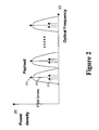
- FIG. 2 is a graphical representation illustrating one embodiment of optical packets in a fiber optic network.
- An optical packet 201 may include a payload signal 202 and pilot tones 203 .
- Payload signal 202 has a first power density 204 at a first optical frequency 205 .
- Pilot tones 203 represent the optical packet header signal.
- the pilot tones have a second power density 204 less than the first power density at optical frequency 205 close to the optical frequency of payload signal 202 .
- the optical packet header 3 may be transmitted to an optical to electrical conversion element 11 .
- the optical to electrical conversion element may comprise a photo diode 11 .
- the electrical signal resulting from the optical to electrical conversion at element 11 may be transmitted to electrical frequency detector 12 .
- the electrical frequency detector may comprise a phase-locked loop (“PLL”).
- PLL 12 phase-locked loop
- the output of PLL 12 is an electrical control signal 13 which may be input into switch controller 14 .
- a feedback signal from PLL 12 may be input into optical pilot tone eraser 10 .
- the feedback signal may be used to provide the “eraser” function for the packet header.
- the feedback signal may act as a subtrahend.
- the feedback signal may have a magnitude that is exactly the same as the magnitude at the frequency of the incoming packet header but with the opposite sign.
- a summation function inside the optical pilot tone eraser 10 results in a sum of “0” for the header after the optical pilot tone eraser 10 .
- an eraser function for the packet header is performed.
- Switch controller 14 may comprise a fast memory forwarding table 15 .
- the fast memory forwarding table 15 may separate the electrical control signal 13 into four portions.
- the separated electrical control signal 13 may include an incoming label representing a searching index, an ingress port identifier identifying the ingress port at which packet 1 entered the switch 100 , an egress port identifier identifying from which egress port optical packet 1 should be transmitted and an outgoing label representing the next destination for the optical payload 2 and, if necessary, the new optical transmission wavelength for the optical packet header 3 .
- the information contained in the optical packet header 3 may be pre-calculated before the packet is transmitted from its origin.
- the switch controller 14 may use the information in fast memory forwarding table 15 , derived from the electrical control signal 13 , to control switch fabric 23 .
- the switch controller may also forward the new optical payload header including the new labels to synthesizer 16 .
- Synthesizer 16 may convert the electrical signal of the optical packet header to an optical signal to produce optical packet header 3 ′.
- the synthesizer 16 may provide an electrical frequency output (tone) with static input from switch controller 14 . For example, if the switch controller 14 outputs a set of DC electrical values, the output signal of the synthesizer would be a pre-defined frequency (tone).
- the synthesizer 16 may then forward new optical packet header 3 ′ to pilot tone modulation module 21 .
- Pilot tone modulation module 21 may work with synthesizer 16 to modulate the electrical pilot signal into the new optical packet header 3 ′.
- the new optical packet header 3 ′ may be forwarded from pilot tone modulation module 21 to optical signal combiner/tuner 22 .
- the new optical packet header 3 ′ may be associated with optical payload 2 . While the optical packet header 3 is processed to determine the ingress/egress ports or switching paths through which optical packet payload 2 may be switched, optical packet payload 2 may be routed through fiber delay 18 .
- Fiber delay 18 may include optical fiber or optical storage means to delay the optical payload 2 until the switching path has been determined.
- the fiber delay 18 may include a fixed delay and/or programmable delay.
- the fixed delay may correspond to the processing time for optical packet header 3 .
- the programmable delay may be determined by optical signal tuner 22 .
- the optical signal tuner may delay receiving the payload 2 if there is contention from another payload portion of another optical packet routed to go through the same egress port as payload 2 .
- optical packet payload 2 and the new optical packet header 3 ′ may be combined in optical signal combiner 22 . If there is contention from another payload routed through the same egress port, optical signal tuner 22 may change one of the payload signals 2 and/or is corresponding optical packet header 3 ′ to a different optical transmission wavelength.
- the optical signal tuner may comprise tunable laser technology.
- the modified optical packet 1 ′ may be switched through switch fabric 23 and transmitted to its next destination.
- the next destination may comprise either an optical user network interface, if the next destination is the optical packet's 1 ′ final destination, or an optical network interface, if the next destination is not the optical packet's 1 ′ final destination.
- FIG. 3 is a block diagram illustrating one embodiment of an all-optical switching system receiving a plurality of packets through the same fiber and frequency. All-optical switching system 300 may receive optical packets 311 , 321 at an optical transmission wavelength of ⁇ 1 through fiber 1 .
- Optical packet 311 and optical packet 321 may each be routed through the all-optical switching system 300 as described with reference to FIG. 1 above.
- Optical packets 311 , 312 may be routed to the appropriate fiber and converted to an optical transmission wavelength depending on the information contained in their corresponding optical packet headers.
- optical packet 311 may be routed to fiber 4 and re-coded to an optical transmission wavelength of ⁇ 3 .
- Optical packet 321 may be routed to fiber 2 and re-coded to an optical transmission wavelength of ⁇ 15 .
- the re-coding of the payload signal and the header performed in optical signal tuner 22 may be performed before switch fabric 23 or after switch fabric, depending on the implementation.
- the routing paths for each packet 311 , 321 may be pre-calculated and a signaling protocol such as, for example, wavelength distribution protocol (“WDP”) may be used to pre-configure the label on each of the switches 100 along the path.
- WDP wavelength distribution protocol
- a signaling protocol within switch controller 14 may be configured to convert all optical packet headers 3 having a first type of optical packet label to a predetermined second optical packet label.
- FIG. 4 is a block diagram illustrating one embodiment of a portion of a network including a plurality of switches.
- a network may include switches 400 , 410 , 420 .
- switches 400 , 410 , 420 are shown for illustration purposes only.
- a network may have more or fewer switches, depending on the implementation.
- An optical packet 401 entering a switch 400 may having an optical transmission wavelength of ⁇ 4 .
- All-optical packet switching system 400 may convert the optical transmission frequency at which optical packet 401 is transmitted to ⁇ 3 during switching and transmit the switched packet 401 ′ to switch 410 .
- All-optical switching system 410 may convert the optical transmission frequency at which packet 401 ′ is transmitted to an optical transmission wavelength ⁇ 2 during switching. Switch 410 may then transmit switched packet 401 ′′ to switch 420 .
- All-optical switching system 420 may convert the optical transmission wavelength ⁇ 2 of packet 401 ′′ to an optical transmission wavelength of ⁇ 1 during switching of optical packet 401 ′′ to optical packet 401 ′′′.
- optical packet 401 ′′′ may be reconverted to an electrical packet format and the optical label of optical packet 401 ′′′ may be remapped back to the IP address.
- the label remapping from the optical address domain (optical WDM network) to the electrical address domain (IP packet network) may be performed by removing the optical pilot signal 203 , converting the optical payload signal 202 to IP packets, and assigning a destination IP address to each packet.
- the relationship between the optical label and the IP address may be determined by a wavelength signaling protocol at the time the optical path is developed.
- FIG. 5 is a block diagram illustrating one embodiment of a portion of a network comprising a plurality of all-optical switches.
- the network is illustrated having three switches 500 , 510 , 520 . As described above with reference to FIG. 4, the network may have more or fewer switches.
- Switching system 500 is shown, for illustration purposes, as receiving a plurality of input fibers F 1 , F 2 . All of the switches 500 , 510 , 520 may include a plurality of input and output fibers.
- optical packets 501 and 511 are received at ingress ports of the switching system 500 .
- Optical packet 501 is received, in the example shown, at an optical transmission wavelength of ⁇ 4 through a first fiber, F 1 .
- Optical packet 511 is received at an optical transmission wavelength of ⁇ 5 through a second fiber, F 2 .
- switching system 500 may switch packets 501 and 511 to the same optical transmission wavelength ⁇ 3 .
- optical packet 501 and optical packet 511 may be switched by all-optical switching system 500 so that switched packet 501 ′ and switched packet 511 ′ are both transmitted from optical switching system 500 at an optical transmission wavelength of ⁇ 3 through the same output fiber. Further, switched packet 501 ′ and 511 ′ will continue to be switched and transmitted at the same optical transmission wavelength and through the same fiber.
- all-optical switching system 510 may switch optical packet 501 ′ and optical packet 511 ′ to optical packet 501 ′′ and optical packet 511 ′′.
- Optical packets 501 ′′ and 511 ′′ may be transmitted at an optical transmission wavelength of ⁇ 2 .
- optical packet 501 ′′ and optical packet 511 ′′ may be switched to optical packet 501 ′′′ and optical packet 511 ′′′, and transmitted at the same optical transmission wavelength of ⁇ 1 .
- FIG. 6 is a flow diagram illustrating one embodiment of a method for switching packets in an optical switch.
- a packet may be received in the optical switch 100 .
- the header of the packet may be disassociated from the payload of the packet.
- a second header 3 ′ may be formed based on information contained in the first header 3 .
- the payload 2 may be associated with the second header 3 ′.
- the modified packet 1 ′ may be switched.
- the all-optical switch 100 may receive an optical packet 1 including a payload 2 and a header 3 .
- the optical switch 100 may receive one or more packets.
- the optical packet may be received at a first optical transmission wavelength ⁇ 4 .
- the optical packet may be received over an optical fiber F 1 . If a plurality of optical packets 1 are received, the optical packets may all be received over one optical fiber or a plurality of optical fibers.
- the header 3 is disassociated from the payload 2 as described above with reference to FIG. 1 .
- the optical header 3 may be converted into an electrical control signal 13 using an optical to electrical converter 11 .
- the optical header 3 may include a label containing routing information for the optical packet 3 , an identification of the ingress port of the optical packet 1 in the switch 100 , information identifying which egress port the optical packet 1 should be switched to, and information indicating an output label for the optical packet header 3 .
- the output label for the optical packet header 3 may be determined by a pre-configured signaling protocol.
- the pre-configured signaling protocol may determine the outgoing label for the optical packet header 3 based on the optical frequency of the pilot tone 203 of the optical packet header 3 .
- the pre-configured signaling protocol may convert all optical packet headers having a first optical transmission frequency or wavelength to a second predetermined optical transmission wavelength.
- the second header 3 ′ may be associated with the payload 2 .
- the payload 2 may be delayed in a fiber delay 18 until the second header 3 ′ is ready to be associated with the payload 2 .
- the second header 3 ′ may be converted from an electrical signal to an optical signal before being associated with payload 2 to form the modified packet 1 ′.
- the optical transmission wavelength of the modified packet 1 ′ may be converted from a first optical transmission wavelength at which optical packet 1 was received such as, for example, ⁇ 4 , to a second optical transmission wavelength, such as, for example, ⁇ 3 .
- the modified packet transmission wavelength may be changed due to a second optical data packet payload 2 waiting to use the same egress port at the same frequency as the first optical data packet 1 . Converting the wavelength of the modified packet 1 may occur before or after switching the modified packet.
- the modified packet 1 ′ may be switched to be transmitted through the appropriate egress port and fiber.
- the optical transmission wavelength of one or both of the optical packets 311 , 321 may be changed so that modified optical packets 311 ′, 321 ′ are transmitted at different wavelengths, such as optical transmission wavelength ⁇ 3 and optical transmission wavelength ⁇ 15 .
- two optical data packets 501 , 511 may be received over different optical transmission wavelengths at optical switch 500 . If the network destination information contained in the optical packet header 3 of optical packet 501 matches the network address information contained in the optical packet header 3 of optical data packet 511 , modified optical packet 501 ′ and modified optical packet 511 ′ may be transmitted over the same optical wavelength. In the example in FIG. 5, optical packet 501 is received at an optical transmission frequency of ⁇ 4 and optical packet 511 ′ is received at an optical transmission wavelength of ⁇ 5 . After being switched at all-optical packet switch 500 , modified optical packet 501 ′ and modified optical packet 511 ′ may be transmitted at the same optical transmission wavelength ⁇ 3 .
Abstract
Description
Claims (30)
Priority Applications (1)
| Application Number | Priority Date | Filing Date | Title |
|---|---|---|---|
| US09/745,867 US6788896B1 (en) | 2000-12-26 | 2000-12-26 | Technique for all-optical packet switching |
Applications Claiming Priority (1)
| Application Number | Priority Date | Filing Date | Title |
|---|---|---|---|
| US09/745,867 US6788896B1 (en) | 2000-12-26 | 2000-12-26 | Technique for all-optical packet switching |
Publications (1)
| Publication Number | Publication Date |
|---|---|
| US6788896B1 true US6788896B1 (en) | 2004-09-07 |
Family
ID=32928082
Family Applications (1)
| Application Number | Title | Priority Date | Filing Date |
|---|---|---|---|
| US09/745,867 Expired - Fee Related US6788896B1 (en) | 2000-12-26 | 2000-12-26 | Technique for all-optical packet switching |
Country Status (1)
| Country | Link |
|---|---|
| US (1) | US6788896B1 (en) |
Cited By (7)
| Publication number | Priority date | Publication date | Assignee | Title |
|---|---|---|---|---|
| US20040151497A1 (en) * | 2003-02-05 | 2004-08-05 | Ki-Cheol Lee | Wavelength path monitoring/correcting apparatus in transparent optical cross-connect and method thereof |
| US20050105906A1 (en) * | 2002-01-30 | 2005-05-19 | Barbosa Felipe R. | Apparatus, system and method for optical packet switching using frequency header |
| US20070065149A1 (en) * | 2005-09-20 | 2007-03-22 | Stevens Rick C | Data communication network using optical power averaged multiplexing |
| US20100104279A1 (en) * | 2006-06-29 | 2010-04-29 | Nortel Networks Limited | Method and system for configuring a connection-oriented packet network over a wavelength division multiplexed optical network |
| US20120328284A1 (en) * | 2011-06-24 | 2012-12-27 | Wataru Kawasaki | Optical packet switching apparatus |
| US9014562B2 (en) | 1998-12-14 | 2015-04-21 | Coriant Operations, Inc. | Optical line terminal arrangement, apparatus and methods |
| CN106063169A (en) * | 2014-03-06 | 2016-10-26 | 华为技术有限公司 | Data processing method and device |
Citations (5)
| Publication number | Priority date | Publication date | Assignee | Title |
|---|---|---|---|---|
| US5430715A (en) * | 1993-09-15 | 1995-07-04 | Stratacom, Inc. | Flexible destination address mapping mechanism in a cell switching communication controller |
| US6032190A (en) * | 1997-10-03 | 2000-02-29 | Ascend Communications, Inc. | System and method for processing data packets |
| US6519062B1 (en) * | 2000-02-29 | 2003-02-11 | The Regents Of The University Of California | Ultra-low latency multi-protocol optical routers for the next generation internet |
| US6545781B1 (en) * | 1998-07-17 | 2003-04-08 | The Regents Of The University Of California | High-throughput, low-latency next generation internet networks using optical label switching and high-speed optical header generation, detection and reinsertion |
| US6657757B1 (en) * | 1998-07-17 | 2003-12-02 | The Regents Of The University Of California | High-throughput low-latency next generation internet network using optical label switching and high-speed optical header generation detection and reinsertion |
-
2000
- 2000-12-26 US US09/745,867 patent/US6788896B1/en not_active Expired - Fee Related
Patent Citations (5)
| Publication number | Priority date | Publication date | Assignee | Title |
|---|---|---|---|---|
| US5430715A (en) * | 1993-09-15 | 1995-07-04 | Stratacom, Inc. | Flexible destination address mapping mechanism in a cell switching communication controller |
| US6032190A (en) * | 1997-10-03 | 2000-02-29 | Ascend Communications, Inc. | System and method for processing data packets |
| US6545781B1 (en) * | 1998-07-17 | 2003-04-08 | The Regents Of The University Of California | High-throughput, low-latency next generation internet networks using optical label switching and high-speed optical header generation, detection and reinsertion |
| US6657757B1 (en) * | 1998-07-17 | 2003-12-02 | The Regents Of The University Of California | High-throughput low-latency next generation internet network using optical label switching and high-speed optical header generation detection and reinsertion |
| US6519062B1 (en) * | 2000-02-29 | 2003-02-11 | The Regents Of The University Of California | Ultra-low latency multi-protocol optical routers for the next generation internet |
Non-Patent Citations (2)
| Title |
|---|
| "A Proof-of-Concept, Ultra-low Latency Optical Label Switching Testbed Demonstration for Next Generation Internet Networks," by G.K. Chang et al., Proceedings of the Optical Communication Conference, Baltimore, Maryland, WDS, Mar. 2000, pp. 56-58. |
| "All-Optical Label Swapping with Wavelength Conversion for WDM-IP Networks with Subcarrier Multiplexed Addressing," by D.J. Blumenthal et al., IEEE Photonics Technology Letters, vol. 11, No. 11, Nov. 1999. |
Cited By (17)
| Publication number | Priority date | Publication date | Assignee | Title |
|---|---|---|---|---|
| US9014562B2 (en) | 1998-12-14 | 2015-04-21 | Coriant Operations, Inc. | Optical line terminal arrangement, apparatus and methods |
| US7577358B2 (en) * | 2002-01-30 | 2009-08-18 | Ericsson Telecomunicacoes S.A. | Apparatus, system and method for optical packet switching using frequency header |
| US20050105906A1 (en) * | 2002-01-30 | 2005-05-19 | Barbosa Felipe R. | Apparatus, system and method for optical packet switching using frequency header |
| US7200329B2 (en) * | 2003-02-05 | 2007-04-03 | Samsung Electronics Co Ltd | Wavelength path monitoring/correcting apparatus in transparent optical cross-connect and method thereof |
| US20040151497A1 (en) * | 2003-02-05 | 2004-08-05 | Ki-Cheol Lee | Wavelength path monitoring/correcting apparatus in transparent optical cross-connect and method thereof |
| US20070065149A1 (en) * | 2005-09-20 | 2007-03-22 | Stevens Rick C | Data communication network using optical power averaged multiplexing |
| US7706685B2 (en) | 2005-09-20 | 2010-04-27 | Lockheed Martin Corporation | Data communication network using optical power averaged multiplexing |
| US8824887B2 (en) | 2006-06-29 | 2014-09-02 | Rockstar Consortium Us Lp | Method and system for configuring a connection-oriented packet network over a wavelength division multiplexed optical network |
| US7925161B2 (en) | 2006-06-29 | 2011-04-12 | Nortel Networks Limited | Method and system for configuring a connection-oriented packet network over a wavelength division multiplexed optical network |
| US20100104279A1 (en) * | 2006-06-29 | 2010-04-29 | Nortel Networks Limited | Method and system for configuring a connection-oriented packet network over a wavelength division multiplexed optical network |
| US20110222852A1 (en) * | 2006-06-29 | 2011-09-15 | Nortel Networks Limited | Method and system for configuring a connection-oriented packet network over a wavelength division multiplexed optical network |
| US8718470B2 (en) * | 2011-06-24 | 2014-05-06 | Fujitsu Telecom Networks Limited | Optical packet switching apparatus |
| US20120328284A1 (en) * | 2011-06-24 | 2012-12-27 | Wataru Kawasaki | Optical packet switching apparatus |
| CN106063169A (en) * | 2014-03-06 | 2016-10-26 | 华为技术有限公司 | Data processing method and device |
| EP3107231A4 (en) * | 2014-03-06 | 2017-03-08 | Huawei Technologies Co., Ltd. | Data processing method and device |
| US9913010B2 (en) | 2014-03-06 | 2018-03-06 | Huawei Technologies Co., Ltd. | Data processing method and apparatus |
| CN106063169B (en) * | 2014-03-06 | 2019-05-07 | 华为技术有限公司 | A kind of data processing method and device |
Similar Documents
| Publication | Publication Date | Title |
|---|---|---|
| JP3507438B2 (en) | High-throughput, low-latency next-generation internet network using optical tag switching | |
| US8264967B2 (en) | Bit-field-encoded resource record for determining a transmission path in a communications network | |
| US5317658A (en) | Apparatus and method for providing a polarization independent optical switch | |
| US7369766B2 (en) | Optically boosted router | |
| EP1130942B1 (en) | Integration of all-optical crossconnect functionality in an optical packet switching apparatus | |
| WO2001086998A1 (en) | Optical transport networks | |
| JP2002009696A (en) | Method and system for transmission of optical data, optical transmitter, optical transmission method and optical converter | |
| US6788896B1 (en) | Technique for all-optical packet switching | |
| EP1472902B1 (en) | Apparatus, system and method for optical packet switching using frequency header | |
| US7596316B2 (en) | Method of sending packet-formed information optically using different wave-lengths for address and useful information | |
| JP2002026874A (en) | Optical communication unit | |
| US7171117B1 (en) | Optical router | |
| EP3430737B1 (en) | Segment routing for optical networks | |
| US20060053221A1 (en) | Packet communication network, route control server, route control method, packet transmission device, admission control server, light wavelength path setting method, program, and recording medium | |
| JP2004080633A (en) | Data multiplexing network, frequency multiplexer, and data multiplexing/transmitting method | |
| US7133613B2 (en) | Address determination circuit and optical communication system | |
| JP2003198463A (en) | Common clock optical fiber transmission system | |
| JP2009188447A (en) | Method and apparatus for processing optical packet using hierarchy header | |
| US8086103B2 (en) | Methods and apparatus for communicating dynamic optical wavebands (DOWBs) | |
| US20040008685A1 (en) | Multi-protocol label switching device and multi-protocol switching method | |
| JP3229841B2 (en) | ATM communication network | |
| Jennen | IP over DWDM networks supported by GMPLS-based LOBS deploying combined modulation format | |
| JPH05183564A (en) | Access control system and its node equipment in loop type optical local area network system | |
| JP4033380B6 (en) | Wavelength label type optical router | |
| JP4033380B2 (en) | Wavelength label type optical router |
Legal Events
| Date | Code | Title | Description |
|---|---|---|---|
| AS | Assignment |
Owner name: NORTEL NETWORKS LIMITED, CANADA Free format text: ASSIGNMENT OF ASSIGNORS INTEREST;ASSIGNORS:WANG, GUO-QIANG;GOODWILL, DOMINIC;TOLIVER, PAUL;AND OTHERS;REEL/FRAME:011654/0802;SIGNING DATES FROM 20010321 TO 20010330 |
|
| FPAY | Fee payment |
Year of fee payment: 4 |
|
| AS | Assignment |
Owner name: CIENA LUXEMBOURG S.A.R.L.,LUXEMBOURG Free format text: ASSIGNMENT OF ASSIGNORS INTEREST;ASSIGNOR:NORTEL NETWORKS LIMITED;REEL/FRAME:024213/0653 Effective date: 20100319 Owner name: CIENA LUXEMBOURG S.A.R.L., LUXEMBOURG Free format text: ASSIGNMENT OF ASSIGNORS INTEREST;ASSIGNOR:NORTEL NETWORKS LIMITED;REEL/FRAME:024213/0653 Effective date: 20100319 |
|
| AS | Assignment |
Owner name: CIENA CORPORATION,MARYLAND Free format text: ASSIGNMENT OF ASSIGNORS INTEREST;ASSIGNOR:CIENA LUXEMBOURG S.A.R.L.;REEL/FRAME:024252/0060 Effective date: 20100319 Owner name: CIENA CORPORATION, MARYLAND Free format text: ASSIGNMENT OF ASSIGNORS INTEREST;ASSIGNOR:CIENA LUXEMBOURG S.A.R.L.;REEL/FRAME:024252/0060 Effective date: 20100319 |
|
| FPAY | Fee payment |
Year of fee payment: 8 |
|
| AS | Assignment |
Owner name: DEUTSCHE BANK AG NEW YORK BRANCH, NEW YORK Free format text: SECURITY INTEREST;ASSIGNOR:CIENA CORPORATION;REEL/FRAME:033329/0417 Effective date: 20140715 |
|
| AS | Assignment |
Owner name: BANK OF AMERICA, N.A., AS ADMINISTRATIVE AGENT, NO Free format text: PATENT SECURITY AGREEMENT;ASSIGNOR:CIENA CORPORATION;REEL/FRAME:033347/0260 Effective date: 20140715 |
|
| REMI | Maintenance fee reminder mailed | ||
| LAPS | Lapse for failure to pay maintenance fees | ||
| STCH | Information on status: patent discontinuation |
Free format text: PATENT EXPIRED DUE TO NONPAYMENT OF MAINTENANCE FEES UNDER 37 CFR 1.362 |
|
| FP | Lapsed due to failure to pay maintenance fee |
Effective date: 20160907 |
|
| AS | Assignment |
Owner name: CIENA CORPORATION, MARYLAND Free format text: RELEASE BY SECURED PARTY;ASSIGNOR:DEUTSCHE BANK AG NEW YORK BRANCH;REEL/FRAME:050938/0389 Effective date: 20191028 |
|
| AS | Assignment |
Owner name: BANK OF AMERICA, N.A., AS COLLATERAL AGENT, ILLINO Free format text: PATENT SECURITY AGREEMENT;ASSIGNOR:CIENA CORPORATION;REEL/FRAME:050969/0001 Effective date: 20191028 |
|
| AS | Assignment |
Owner name: CIENA CORPORATION, MARYLAND Free format text: RELEASE BY SECURED PARTY;ASSIGNOR:BANK OF AMERICA, N.A.;REEL/FRAME:065630/0232 Effective date: 20231024 |