US6834066B2 - Stabilization technique for high repetition rate gas discharge lasers - Google Patents
Stabilization technique for high repetition rate gas discharge lasers Download PDFInfo
- Publication number
- US6834066B2 US6834066B2 US09/838,715 US83871501A US6834066B2 US 6834066 B2 US6834066 B2 US 6834066B2 US 83871501 A US83871501 A US 83871501A US 6834066 B2 US6834066 B2 US 6834066B2
- Authority
- US
- United States
- Prior art keywords
- discharge
- capacitor
- peaking
- electrodes
- laser
- Prior art date
- Legal status (The legal status is an assumption and is not a legal conclusion. Google has not performed a legal analysis and makes no representation as to the accuracy of the status listed.)
- Expired - Lifetime, expires
Links
Images


Classifications
-
- H—ELECTRICITY
- H01—ELECTRIC ELEMENTS
- H01S—DEVICES USING THE PROCESS OF LIGHT AMPLIFICATION BY STIMULATED EMISSION OF RADIATION [LASER] TO AMPLIFY OR GENERATE LIGHT; DEVICES USING STIMULATED EMISSION OF ELECTROMAGNETIC RADIATION IN WAVE RANGES OTHER THAN OPTICAL
- H01S3/00—Lasers, i.e. devices using stimulated emission of electromagnetic radiation in the infrared, visible or ultraviolet wave range
- H01S3/09—Processes or apparatus for excitation, e.g. pumping
- H01S3/097—Processes or apparatus for excitation, e.g. pumping by gas discharge of a gas laser
- H01S3/0971—Processes or apparatus for excitation, e.g. pumping by gas discharge of a gas laser transversely excited
-
- H—ELECTRICITY
- H01—ELECTRIC ELEMENTS
- H01S—DEVICES USING THE PROCESS OF LIGHT AMPLIFICATION BY STIMULATED EMISSION OF RADIATION [LASER] TO AMPLIFY OR GENERATE LIGHT; DEVICES USING STIMULATED EMISSION OF ELECTROMAGNETIC RADIATION IN WAVE RANGES OTHER THAN OPTICAL
- H01S3/00—Lasers, i.e. devices using stimulated emission of electromagnetic radiation in the infrared, visible or ultraviolet wave range
- H01S3/14—Lasers, i.e. devices using stimulated emission of electromagnetic radiation in the infrared, visible or ultraviolet wave range characterised by the material used as the active medium
- H01S3/22—Gases
- H01S3/223—Gases the active gas being polyatomic, i.e. containing two or more atoms
- H01S3/225—Gases the active gas being polyatomic, i.e. containing two or more atoms comprising an excimer or exciplex
-
- H—ELECTRICITY
- H01—ELECTRIC ELEMENTS
- H01S—DEVICES USING THE PROCESS OF LIGHT AMPLIFICATION BY STIMULATED EMISSION OF RADIATION [LASER] TO AMPLIFY OR GENERATE LIGHT; DEVICES USING STIMULATED EMISSION OF ELECTROMAGNETIC RADIATION IN WAVE RANGES OTHER THAN OPTICAL
- H01S3/00—Lasers, i.e. devices using stimulated emission of electromagnetic radiation in the infrared, visible or ultraviolet wave range
- H01S3/09—Processes or apparatus for excitation, e.g. pumping
- H01S3/097—Processes or apparatus for excitation, e.g. pumping by gas discharge of a gas laser
- H01S3/09705—Processes or apparatus for excitation, e.g. pumping by gas discharge of a gas laser with particular means for stabilising the discharge
-
- H—ELECTRICITY
- H01—ELECTRIC ELEMENTS
- H01S—DEVICES USING THE PROCESS OF LIGHT AMPLIFICATION BY STIMULATED EMISSION OF RADIATION [LASER] TO AMPLIFY OR GENERATE LIGHT; DEVICES USING STIMULATED EMISSION OF ELECTROMAGNETIC RADIATION IN WAVE RANGES OTHER THAN OPTICAL
- H01S3/00—Lasers, i.e. devices using stimulated emission of electromagnetic radiation in the infrared, visible or ultraviolet wave range
- H01S3/09—Processes or apparatus for excitation, e.g. pumping
- H01S3/097—Processes or apparatus for excitation, e.g. pumping by gas discharge of a gas laser
- H01S3/0975—Processes or apparatus for excitation, e.g. pumping by gas discharge of a gas laser using inductive or capacitive excitation
Definitions
- the present invention relates to laser systems.
- the present invention relates to implementing active loads in the discharge circuitry design of gas discharge lasers to provide stabilization of high repetition rate gas discharge laser systems.
- Pulse gas discharge lasers emitting in the deep ultraviolet (DUV) and vacuum ultraviolet (VUV) region are widely used in various industrial applications such as microlithography, photoablation, and micro-machining, among others.
- DUV deep ultraviolet
- VUV vacuum ultraviolet
- currently used systems include line narrowed excimer lasers, such as ArF (193 nm) lasers and KrF (248 nm) lasers, as well as molecular fluorine (F 2 ) lasers emitting at 157 nm, which are efficient and exhibit high energy stability at high repetition rates, for example, at 1-2 KHz or more.
- FIG. 1 illustrates a schematic arrangement of a pulsed gas discharge electrical circuit of a typical gas discharge laser system.
- a pair of discharge electrodes 101 , 102 is coupled to a discharge circuit which includes a peaking capacitance Cp and an inherent inductance L d between the peaking capacitance Cp and the discharge electrode 101 .
- Such discharge electrical circuitry may be found in current gas discharge lasers such as excimer lasers and molecular fluorine laser systems.
- the area between the discharge electrodes 101 , 102 defines a region referred to as a gas discharge region 103 .
- the pair of elongated discharge electrodes 101 , 102 of the gas discharge laser one of which (in this case, the discharge electrode 102 ) may be connected to a ground or reference potential, are separated by the gas discharge region 103 which is filled with a high pressure laser gas.
- the discharge electrode 101 is connected to the output of the high voltage pulsed generator which is capable of providing fast and powerful charging of the peaking capacitor Cp up to the electrical breakdown voltage of the gas discharge gap.
- Powerful pulsed source(s) or preionization units for providing ultraviolet light in a spark or corona discharge provide an initial preionization of the gas mixture in the discharge region, and are typically positioned in the vicinity of the gas discharge region 103 between the discharge electrodes 101 , 102 .
- the preionizer(s) provide an initial ionization, or preionization, of the laser gas during the charging of the peaking capacitance Cp which receives an electrical pulse initially provided by the charging of a main storage capacitor by a high voltage (HV) power supply when the main storage capacitor is discharged through a switch such as a thyratron or a solid state switch.
- HV high voltage
- the HV electrical circuitry which is used for the excitation of the gas discharge in the pulsed gas laser systems may be schematically sub-divided into two parts.
- the first part of the HV electrical circuitry may include the peaking capacitance Cp which is configured to store electrical energy, and used during the gas breakdown phase.
- the second part of the HV electrical circuitry may include the HV pulsed power generator which is used for the fast and efficient charging of the peaking capacitor Cp up to the breakdown voltage of the gas.
- the HV pulsed power generator may include a suitable HV pulsed device such as a gas filled thyratron, or a solid state switch such as a thyristor or an IGBT).
- a problem encountered with typical pulsed electrical gas discharges in strongly electronegative gas mixtures (i.e., containing a halogen component) at elevated pressures (for example, several bars) is a certain degree of instability.
- the short phase of the uniform glow discharge usually less than 100 nanoseconds, corresponding to the pumping of the laser medium, is typically terminated by rapidly developing streamers.
- the streamers themselves are temporally inconsistent which leads to the discharge instabilities.
- the existence of streamers at the ends of discharges produces excessive wear on the electrodes. In view of these problems caused by streamers, it is desired to suppress them.
- a gas discharge laser including a discharge circuit wherein the main input of the energy into the gas discharge is quickly realized, or that provides very short, intense electrical pulses to the main discharge load, and is terminated without extended and inconsistent streamers reducing the discharge stability from pulse to pulse and without excessively wearing the discharge electrodes.
- a discharge circuit for a pulsed gas laser system in accordance with one embodiment of the present invention includes a pair of spaced-apart electrodes defining a discharge region as a main load, a capacitance coupled to one of the pair of electrodes for providing electrical pulses to the electrodes, and an additional load electrically coupled between the capacitance Cp and one of the discharge electrodes.
- the additional load may include one or more resistors, a resistor array, a resistor or resistor array coupled with a variable inductance and/or a saturable inductance, or another dissipative electrical component for dissipating electrically energy between the main load and the capacitance to facilitate termination of electrical discharges between the electrodes and in turn suppress the formation or influence of streamers.
- the additional load may be coupled in series or in parallel with the capacitance and the main load, and a portion of the additional load may be coupled in series and a portion may be coupled in parallel with the capacitance and the main load. Any series connected portion of the additional load may be coupled to a high voltage or grounded main electrode.
- the resistor or resistors may have a value comparable to a wave impedance of the discharge circuit.
- the resistor or resistors may have a value comparable to an active impedance of the gas discharge during a maximum discharge current phase.
- the additional load is preferably a passive resistance, and may alternatively have an active feature such as a voltage dependence or a temperature dependence.
- the circuit may further include a cooling unit, wherein the additional load is provided in the cooling unit.
- the cooling unit may be provided within a pulsed power module of a laser system which contains electrical components of the discharge circuit particularly susceptible to heating effects.
- the cooling unit may include one of an air fan and an encapsulated volume with circulating isolating fluid.
- One or more preionization units are preferably also provided for ionizing the laser gas within the discharge region between the pair of main electrodes during the charging of the capacitance just prior to discharging through the electrodes.
- the capacitance may include a series of peaking capacitors, and may include a series of sustaining capacitors.
- the sustaining capacitors would be coupled to the electrodes by a different inductance than the peaking capacitors, and would be otherwise preferably coupled within the discharge circuit similarly to the peaking capacitors defining the capacitance coupled to the main electrodes.
- the pair of electrodes, the capacitance and the additional load may form a series configuration such as an electrical loop, or the additional load may be coupled to the electrodes in parallel with the capacitance.
- the circuit further includes a power generator configured to provide power to the capacitance for charging the capacitance.
- the power generator may include a high voltage pulsed power generator.
- the power generator is preferably connected to a main storage capacitor which is charged during a charging cycle.
- a solid state switch is used for discharging the main storage capacitor to the rest of the discharge circuit which preferably includes one or more pulse compression stages before the peaking capacitance connected to the main load.
- a transformer and/or voltage doubling circuit may also be coupled between the main storage capacitor and the pulse compression stages.
- a processor is connected in a pulse energy or energy dose control feedback loop with a detector for providing charging voltage values to which the power supply charges the main storage capacitor between discharges of electrical pulses.
- the circuit may further include a ground terminal coupled to the capacitance.
- a discharge circuit in accordance with another embodiment of the present invention includes a pair of discharge electrodes, an area between the pair of electrodes defining a gas discharge area, a peaking capacitance coupled to one of the pair of discharge electrodes, the peaking capacitance configured to store charge, an additional load including a resistor, resistor array for low inductivity, or a resistance coupled with a saturable or variable inductance is coupled between the discharge electrodes and the peaking capacitance, either in series or in parallel, and a ground or reference voltage terminal is further preferably coupled to the other terminal of the peaking capacitance and the main load or discharge electrodes, where the pair of discharge electrodes, the peaking capacitor and the resistor form an electrical loop.
- a first electrode of the pair of main electrodes is preferably coupled to the peaking capacitance, wherein the additional load is coupled either in series between the peaking capacitance and the first main electrode, and a second main electrode is connected to a ground or reference voltage along with a ground or reference terminal of the peaking capacitance.
- the additional load is also preferably connected to the ground or reference voltage.
- the circuit may further include a cooling unit for cooling the additional load or resistance.
- the gas discharge area may be filled with a high pressure laser gas, e.g., at 2-7 bar, and preferably around 3-5 bar.
- the gas mixture may include molecular fluorine and an active rare gas such as krypton or argon, of a KrF or ArF laser, respectively, while the gas mixture may be pressurized with a buffer gas of neon and/or helium.
- the laser active gas may solely include molecular fluorine such as for a molecular fluorine laser, wherein the buffer gas may include neon and/or helium or a combination thereof.
- a resistor or a resistor array may be connected between the peaking capacitor and high voltage main electrode, while the other discharge electrode is connected to ground or a reference voltage.
- a discharge circuit for use in a laser system in accordance with yet another embodiment of the present invention includes a pair of discharge electrodes, wherein an area between the pair of electrodes defines a gas discharge area.
- a first peaking capacitance is coupled directly to the pair of electrodes.
- a second peaking capacitance is also coupled to the pair of electrodes, wherein a resistance or an otherwise additional load is coupled, either in series or in parallel, between the second peaking capacitance and the discharge electrodes.
- a ground or reference terminal is preferably coupled to the first and second peaking capacitors and a ground electrode of the pair of main discharge electrodes, wherein the pair of discharge electrodes, the second peaking capacitances and the resistance or additional load may form a series electrical loop or parallel electrical combination, while the first peaking capacitance and discharge electrodes form another electrical loop.
- the additional load may include a resistor, a resistor array, a resistor combined with a variable or saturable or saturable inductance, or other means for dissipating electrical energy between the discharge electrodes and the second peaking capacitance.
- the circuit may include a cooling unit for cooling the resistor.
- the circuit may include a high voltage pulsed generator to provide power to the first and second peaking capacitors, and the gas discharge area may include a high pressure laser gas.
- a method of providing a discharge circuit for a pulsed gas laser system in accordance with still a further embodiment of the present invention includes providing a pair of electrodes, coupling a capacitance to a first electrode of the pair of electrodes, the capacitance configured to store charge, and coupling an additional load between the capacitance and the first electrode.
- a further method includes charging a main storage capacitor of a pulsed gas discharge excitation laser system, discharging the main storage capacitor through a pulse compression circuit to a peaking capacitance as an electrical pulse, and dissipating the energy of the electrical pulse through a main load and an additional load, the main load including a discharge region filled with a gas mixture and the additional load including a resistor, resistor array or a resistance coupled with a variable or saturable inductance, and wherein the additional load is coupled either in series between the peaking capacitance and the main load or in parallel with the peaking capacitance.
- the load may include a resistor, and the resistor may have a value comparable to a wave impedance of said discharge circuit, or a value comparable to an active impedance of the gas discharge during a maximum discharge current phase.
- the method may further include the step of providing cooling the additional load, where the step of cooling may include the step of providing either an air fan or an encapsulated volume with circulating oil.
- the method may further include the step of defining a volume between the pair of electrodes as a gas discharge area having a width that allows a clearing ratio of the laser gas to be sufficient in view of the repetition rate of the laser, which may be 2 kHz, 4 kHz or more.
- the method may further include the step of providing ionization of a laser gas in the gas discharge area during the charging of the capacitance.
- the pair of electrodes, the capacitance and the load may form an electrical loop.
- a method of providing a discharge circuit in accordance with yet still another embodiment of the present invention includes defining an area between a pair of discharge electrodes as a gas discharge area, coupling a peaking capacitance to the pair of discharge electrodes, coupling an additional load between one of the discharge electrodes and the peaking capacitance, and coupling a ground or reference voltage terminal to one of the discharge electrodes which couples either directly to a ground terminal of the peaking capacitance or to the peaking capacitance through the additional load, where the pair of discharge electrodes, the peaking capacitance and the additional load form a series or parallel electrical combination.
- a method of providing a discharge circuit for use in a laser system in accordance with yet a further embodiment of the present invention includes providing a pair of discharge electrodes, an region between the pair of electrodes defining a gas discharge region, coupling a first peaking capacitance to the pair of electrodes, and coupling a second peaking capacitance to the pair of electrodes, and coupling a resistance or an otherwise additional load between the second peaking capacitance and the discharge electrodes, and coupling one or the discharge electrodes to ground, along with coupling at least one of the first and second capacitances also to ground, wherein if the additional load is coupled between the second peaking capacitance and the ground discharge electrode, then the second capacitance is coupled to ground through the additional load, and if the additional load is coupled to the high voltage discharge electrode, the the second capacitance is coupled directly to ground, and the first capacitance is coupled directly to ground in either case.
- FIG. 1 illustrates a schematic arrangement of a typical discharge circuit of a gas discharge laser.
- FIG. 2 a illustrates a schematic arrangement of a discharge circuit of a gas discharge laser discharge in accordance with a first embodiment of the present invention.
- FIG. 2 b illustrates a schematic arrangement of an overall discharge circuit of a gas discharge laser in accordance with a preferred embodiment.
- FIG. 3 illustrates a schematic arrangement of a discharge circuit of a gas discharge laser in accordance with a second embodiment of the present invention.
- FIG. 4 illustrates a schematic arrangement of a discharge circuit of a gas discharge laser in accordance with a third embodiment of the present invention.
- FIG. 5 illustrates a schematic arrangement of a discharge circuit of a gas discharge laser in accordance with a fourth embodiment of the present invention.
- FIG. 6 illustrates a schematic arrangement of a discharge circuit of a gas discharge laser in accordance with a fifth embodiment of the present invention.
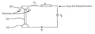
- FIG. 2 a illustrates a schematic arrangement of a laser discharge electrical circuitry in accordance with a first preferred embodiment.
- a pair of discharge electrodes 201 , 202 coupled to a discharge circuit which includes a peaking capacitor Cp and an inherent inductance Ld therebetween.
- the discharge electrical circuitry may be used as part of the overall discharge circuitry of a gas discharge laser such as of an excimer or molecular fluorine laser.
- a gas discharge laser such as of an excimer or molecular fluorine laser.
- U.S. Pat. No. 6,020,723 particularly shows an overall discharge circuit of an excimer or molecular fluorine laser, and more particularly FIG. 2 therein (and which is described in the U.S. Pat. No. 6,020,723 patent wherein that description is not repeated here) which is shown at FIG. 2 b herein, according to a preferred embodiment, wherein the circuit shown at FIG. 2 b herein is preferably modified according the any the preferred embodiments set forth below and schematically illustrates at FIGS. 2 a - 6 .
- the region between the discharge electrodes 201 , 202 is defined as a gas discharge region 203 .
- a resistor R is shown provided between the peaking capacitor Cp and the discharge electrode 201 .
- the peaking capacitor Cp is configured to store electrical energy, and is directly used during the phase of the gas breakdown.
- the HV pulsed power generator of the HV electrical circuitry is used for the fast and efficient charging of the peaking capacitor Cp until the breakdown voltage of the gas.
- the HV pulsed power generator may include any suitable HV pulsed device such as including a gas filled thyratron, or a solid state switch (for example, a thyristor or an IGBT-based switch), for discharging a main storage capacitor through one or more pulse compression stages to the peaking capacitance.
- a transformer is also preferably included between the main storage capacitor and the pulse compression circuit.
- the main storage capacitor is charged by a high voltage power supply which receives signals indicative of charging voltages to be applied to the discharge electrodes from a processor which monitors pulses energies and/or moving average pulse energies or energy doses in a feedback loop with the power supply circuit.
- the resistor R is connected in series between the discharge electrode 201 and the peaking capacitor Cp. In this manner, in accordance with one embodiment of the present invention, the resistor R functions as an additional load in the electrical circuit of the gas discharge electrical loop.
- an additional load such as resistors or a resisitor array may be implemented into the electrical circuitry of the gas discharge.
- the additional load may include a variable or saturable inductor or other dissipative electrical component known to those skilled in the art.
- the resistor may be coupled directly in series with the gas discharge.
- the additional load may be coupled in parallel to the peaking capacitance, and may be partly coupled in series and partly coupled in parallel with the peaking capacitance.
- the value of the resistor may be comparable to the active impedance of the gas discharge during the main phase of the dissipation of the energy in the gas discharge.
- the resistance value may be comparable to the wave impedance of the gas discharge electrical loop, and in particular, may be less or greater than the wave impedance.
- FIG. 3 illustrates a schematic arrangement of a laser discharge electrical circuitry in accordance with a second preferred embodiment.
- a pair of discharge electrodes 301 , 302 the region between which defining a gas discharge region 303 .
- inductance Ld which may be inherent in the circuitry
- a peaking capacitor Cp coupled to the discharge electrode 301 .
- a resistor R is coupled between the discharge electrode 302 and the peaking capacitor Cp.
- the resistor R is coupled between the peaking capacitance and a ground or reference discharge electrode 302 , rather than to the high voltage electrode 301 .
- power from the HV pulsed power generator is applied to the discharge electrode 301 , which, as discussed above, is used for charging the peaking capacitor Cp until the breakdown voltage of the gas.
- the power from the HV pulsed power generator in the embodiment shown in FIG. 2 is applied at a node between the resistor R and the peaking capacitor Cp.
- a resistor R is placed in series between the peaking capacitors Cp and at least one of the main discharge electrodes (electrode 201 in FIG. 2, and electrode 302 in FIG. 3) of the gas discharge laser (such as, for example, an excimer laser or a molecular fluorine laser) to add additional loads between the peaking capacitor Cp and the at least one of the discharge electrodes.
- the resistor R may be replaced by other circuit elements, e.g., CuSO 4 solutions which adds additional active loads between the peaking capacitor Cp and the at least one of the discharge electrodes.
- the cooling element may include an air fan or an encapsulated volume (box) with circulating oil or other insulating fluid (provided for insulation). More specifically, in the latter case of the insulating fluid, the fluid could be cooled by means of a heat exchanger with cold line water.
- the encapsulated box in one aspect may be fabricated with dielectric or metal with feedthroughs for the connection of the resistor(s) R to the element of the gas discharge loop.
- the placement of the resistor(s) R in the laser discharge circuit may require some efforts in cooling.
- additional equipment for cooling the resistor(s) R may be incorporated into the laser arrangement.
- the resistor(s) R in one aspect may be implemented into the laser pulsed power module which itself requires a cooling unit. In this approach, additional cooling unit may be unnecessary.
- the laser pulsed power module may have distributed multiple outputs rather than a single output, connected directly to the laser discharge electrodes or to the peaking capacitor Cp arrangement around the laser discharge electrodes (laser discharge chamber).
- FIG. 4 illustrates a schematic arrangement of a laser discharge electrical circuitry in accordance with yet another embodiment of the present invention.
- a pair of discharge electrodes 401 , 402 with the area between the two electrodes 401 , 402 defining a gas discharge area 403 .
- inductances Ld 1 and Ld 2 which may be inherent to the circuitry shown and differ in value preferably due to there being different lengths of connecting conductors between the first and second peaking capacitors and the electrodes 401 , first and second peaking capacitors Cp 1 and Cp 2 respectively coupled to the discharge electrode 402 .
- a resistor R is provided between the discharge electrode 401 and the second peaking capacitor Cp 2 , wherein the resistor or otherwise additional load may be connected between either peaking capacitance Cp 1 or Cp 2 and the electrode 402 , or some or all of the additional load may be connected in parallel with the capacitance Cp 1 and/or Cp 2 .
- the power from the HV pulsed power generator is applied as shown at a node between the first peaking capacitor Cp 1 and the discharge electrode 401 , and at a node between the second peaking capacitor Cp 2 and the resistor R.
- the discharge circuit shown in FIG. 4 may be configured to act similar to a spiker-sustainer discharge circuit, or may be otherwise configured as set forth at U.S. patent application Ser. No. 09/640,595, which is assigned to the same assignee as the present application and is hereby incorporated by reference.
- the first peaking capacitor Cp 1 is positioned as close as possible to the electrode 401 and thus the gas discharge chamber to provide fast electrical pumping to near the steady state discharge level.
- the second peaking capacitor Cp 2 is connected to the electrodes 401 , 402 via the resistor R.
- the resistor R stabilizes the current through the discharge during the steady state discharge.
- the discharge itself divides the entire peaking capacity in a “spiker-part” (i.e., Cp 1 and a “sustainer-part” (Cp 2 )). In this case, there may be no need for additional saturable inductivities.
- the approach shown in FIG. 4 is not limited to the discharge circuit shown in FIG. 4, but may be applied to similar circuits for pulsed discharges, and further, also for values of the resistors less than or equal to 0.01 Ohms.
- additional load such as resistors may be implemented into the electrical circuitry of the gas discharge.
- the resistor may be coupled in series with the gas discharge.
- the value of the resistor may be comparable to the active impedance of the gas discharge during the main phase of the dissipation of the energy in the gas discharge.
- the resistance value may be comparable to the wave impedance of the gas discharge electrical loop, and in particular, in principle, may be less or greater than the wave impedance.
- resistors of type KOAOHM HPC5-K 22 Ohm which is 44 mm in length and 8 mm in diameter, is connected in parallel from 10 to 40 pieces.
- the resulting data is shown below in Table 1 which was measured with KrF laser.
- the dissipated energy in the discharge region is reduced by 29.6%
- the efficiency (output energy/energy stored in the discharge volume) has be increased by 19.8% in comparison to the case of no additional load.
- Implementing additional resistors in the gas discharge electrical loop may reduce the laser output energy.
- the decrease in the laser output energy is not proportional to the decrease of the energy dissipated in the gas discharge which takes place due to the simultaneous dissipation of the energy in the resistors.
- the laser efficiency determined from the power dissipated in the gas discharge may be increased, which, in turn, indicates that part of the losses in this case could be shifted to the resistors placed outside of the laser tube. This is significant for laser operation at the high repetition rates, while allowing a reduction of the thermal load of the laser tube (i.e., the laser electrodes and laser gas).
- the issue of cooling the laser gas inside the laser tube could be in part, replaced by the cooling of the resistor(s) placed outside of the laser tube. This may also have a positive impact upon the blowing of the laser gas between the discharge electrodes. In other words, while the stress of the discharge electrodes and gas may be less, the necessary gas velocity could be reduced.
- the resistors of the gas discharge circuitry may make the gas discharge more soft and uniform, thus improving the laser output pulse-to-pulse energy stability.
- the performance of the laser system at a high repetition rates may be improved, thus improving the lifetime of the laser tube and laser gas.
- the peaking capacitors may be equivalent and be positioned as close as possible to the gas discharge chamber to provide fast and powerful electrical pumping of the laser active volume which is designed for the excimer or molecular fluorine laser systems. Furthermore, the peaking capacitors may be further subdivided into several groups of capacitors with different connection inductivities to the gas discharge electrodes, and may have different HV power generators, or operate as the transforming lines. In this regard, it should be noted that the HV electrical circuitry may include additional elements and sub-circuits connected between the main gas discharge electrodes for correction of the waveform of the high voltage pulse applied between the electrodes.
- one aspect of the present invention is directed to implementing additional loads (e.g. resistors or resistor arrays or resistors or resistor array coupled with one or more variable or saturable inductors) in the peaking circuit and in particular coupled in series with the discharge.
- additional loads e.g. resistors or resistor arrays or resistors or resistor array coupled with one or more variable or saturable inductors
- the value of the resistor may be comparable to the active impedance of the gas discharge during the main phase of the dissipation of the energy in the gas discharge.
- the resistance value may be comparable to the wave impedance of the gas discharge electrical loop, and in particular, in principle, may be less or greater than the wave impedance.
- FIG. 5 schematically illustrates a fourth preferred embodiment.
- the fourth embodiment is similar to that described above and shwon at FIG. 2 .
- the difference between the fourth and first embodiments is that a variable or saturable inductance L′ is inserted between the peaking capacitance and the discharge electrode 501 .
- a variable or saturable inductance L′ may be similarly inserted into the circuits shown and described with respect to either of the second or third embodiments of FIG. 3 or 4 , as well.
- FIG. 6 schematically illustrates a fifth preferred embodiment.
- the general feature of the fifth embodiment of FIG. 6 is that the additional load is inserted in parallel with the peaking capacitance Cp and the electrodes 601 , 602 .
- the circuit of the fifth embodiment may or may not include the variable or saturable inductance L′ in series with the resistance R, i.e., inclusion of the variable or saturable inductance is optional.
- any of the preferred embodiments described above and shown at FIGS. 1-5 may be modified such that all or a part of the additional load is coupled in parallel with the peaking capacitance Cp, Cp 1 and/or Cp 2 .
- variable or saturable inductance L′ may be coupled in series with the peaking capacitance and either electrode 601 , 602 while the resistance R is coupled in parallel, as shown in FIG. 6, and the resistance R may be coupled in series with either of the electrodes 601 , 602 while the variable or saturable inductance L′ is coupled in parallel, as shown in FIG. 6 .
Abstract
Description
| TABLE 1 | |||
| Resistance-Ohm | 1.83333 | 1.1 | 0.6875 |
| Estor, J (stored energy) | 2.888 | 2.888 | 2.888 |
| Eres, J (dissipated energy) | 0.91281 | 0.78639 | 0.85369 |
| Eres, % from Estor (dissipated energy) | 31.6069 | 27.2295 | 29.5599 |
| (Estor-Eres), J | 1.97519 | 2.10161 | 2.03431 |
| (Estor-Eres), % from Estor | 68.3931 | 72.7705 | 70.4401 |
| Eout, mJ | 30.6 | 35 | 38.1 |
| (laser output energy) | |||
| Eff, tot, % | 1.05956 | 1.21191 | 1.31925 |
| Eff, -res, % | 1.54922 | 1.66539 | 1.87287 |
| Eout0, mJ without |
45 | 45 | 45 |
| Eout, % from Eout0 | 68 | 77.7778 | 84.6667 |
| Eff, % without resistors | 1.55817 | 1.55817 | 1.55817 |
Claims (30)
Priority Applications (1)
| Application Number | Priority Date | Filing Date | Title |
|---|---|---|---|
| US09/838,715 US6834066B2 (en) | 2000-04-18 | 2001-04-18 | Stabilization technique for high repetition rate gas discharge lasers |
Applications Claiming Priority (2)
| Application Number | Priority Date | Filing Date | Title |
|---|---|---|---|
| US19805800P | 2000-04-18 | 2000-04-18 | |
| US09/838,715 US6834066B2 (en) | 2000-04-18 | 2001-04-18 | Stabilization technique for high repetition rate gas discharge lasers |
Publications (2)
| Publication Number | Publication Date |
|---|---|
| US20020012371A1 US20020012371A1 (en) | 2002-01-31 |
| US6834066B2 true US6834066B2 (en) | 2004-12-21 |
Family
ID=22731826
Family Applications (1)
| Application Number | Title | Priority Date | Filing Date |
|---|---|---|---|
| US09/838,715 Expired - Lifetime US6834066B2 (en) | 2000-04-18 | 2001-04-18 | Stabilization technique for high repetition rate gas discharge lasers |
Country Status (2)
| Country | Link |
|---|---|
| US (1) | US6834066B2 (en) |
| WO (1) | WO2001084678A2 (en) |
Cited By (4)
| Publication number | Priority date | Publication date | Assignee | Title |
|---|---|---|---|---|
| US20050058172A1 (en) * | 2003-09-11 | 2005-03-17 | Rainer Paetzel | System and method for segmented electrode with temporal voltage shifting |
| US20060227839A1 (en) * | 2005-03-31 | 2006-10-12 | Cymer, Inc. | Gas discharge laser output light beam parameter control |
| US20110180729A1 (en) * | 2010-01-22 | 2011-07-28 | Newport Corporation | Broadly tunable optical parametric oscillator |
| US10868344B2 (en) * | 2016-02-25 | 2020-12-15 | Ford Global Technologies, Llc | Entropy driven thermal and electrical management |
Families Citing this family (1)
| Publication number | Priority date | Publication date | Assignee | Title |
|---|---|---|---|---|
| JP5146023B2 (en) * | 2008-03-11 | 2013-02-20 | セイコーエプソン株式会社 | Light source device, illumination device, monitor device, and image display device using drive circuit of semiconductor light emitting element |
Citations (153)
| Publication number | Priority date | Publication date | Assignee | Title |
|---|---|---|---|---|
| US3858056A (en) | 1974-01-22 | 1974-12-31 | Westinghouse Electric Corp | Means and method for stabilized optimized temperature phase matched optical parametric generation |
| US3962576A (en) | 1974-01-25 | 1976-06-08 | Carl Zeiss-Stiftung | Method and apparatus for automatic generation of phase-adapted coherent secondary radiation in a non-linear crystal |
| US4201949A (en) * | 1977-07-27 | 1980-05-06 | Robbins Gene A | Portable gas laser and power supply |
| US4240044A (en) | 1979-07-16 | 1980-12-16 | Gte Products Corporation | Pulsed laser electrode assembly |
| US4245194A (en) * | 1979-07-16 | 1981-01-13 | Gte Products Corporation | Compact pulsed gas transport laser |
| US4380079A (en) | 1980-09-12 | 1983-04-12 | Northrop Corp. | Gas laser preionization device |
| US4393505A (en) | 1978-07-24 | 1983-07-12 | Gte Sylvania Incorporated | Gas discharge laser having a buffer gas of neon |
| US4399540A (en) | 1979-05-10 | 1983-08-16 | Lamba Physik Gesellschaft Zur Herstellung Von Lasern Mbh & Co. Kg | Tunable laser oscillator |
| US4606034A (en) * | 1985-02-19 | 1986-08-12 | Board Of Trustees, University Of Illinois | Enhanced laser power output |
| US4611270A (en) | 1983-09-16 | 1986-09-09 | Questek Incorporated | Method and means of controlling the output of a pulsed laser |
| US4616908A (en) | 1984-07-19 | 1986-10-14 | Gca Corporation | Microlithographic system |
| US4686682A (en) | 1984-10-09 | 1987-08-11 | Mitsubishi Denki Kabushiki Kaisha | Discharge excitation type short pulse laser device |
| US4691322A (en) | 1985-01-22 | 1987-09-01 | Kabushiki Kaisha Komatsu Seisakusho | Gas laser device |
| US4718072A (en) | 1983-12-29 | 1988-01-05 | Enea - Comitato Nazionale Per La Ricerca E Lo Sviluppo Della Energia Nucleare E Delle Energie Alternative | Corona discharge preionizer for gas laser |
| US4719637A (en) | 1985-03-13 | 1988-01-12 | Enea-Comitato Nazionale Per La Ricerca E Lo Sviluppo Dell'energia Nucleare E Delle Energie Alternative | Laser doped with tripropylamine |
| US4763093A (en) | 1985-08-21 | 1988-08-09 | Kraftwerk Union Aktiengesellschaft | High-power pulse transformer for short high-voltage and/or high-current pulses |
| US4797888A (en) * | 1986-06-23 | 1989-01-10 | Lambda Physik | Circuit for the preionization and main discharge of a pulsed gas laser |
| US4829536A (en) | 1986-06-09 | 1989-05-09 | Kabushiki Kaisha Komatsu Seisakusho | Multi-mode narrow-band oscillation excimer laser |
| US4856018A (en) | 1986-01-22 | 1989-08-08 | Kabushiki Kaisha Komatsu Seisakusho | Light source for reduced projection |
| US4860300A (en) | 1987-06-03 | 1989-08-22 | Lambda Physik Forschungs- Und Entwicklungsgesellschaft Mb | Electrode for pulsed gas lasers |
| US4891818A (en) | 1987-08-31 | 1990-01-02 | Acculase, Inc. | Rare gas-halogen excimer laser |
| US4905243A (en) | 1987-12-28 | 1990-02-27 | Lambda Physik Forschungs-Und Entwicklungs-Gmbh | Method and apparatus for stabilizing the frequency of a laser beam |
| US4926428A (en) | 1987-08-31 | 1990-05-15 | Kabushiki Kaisha Komatsu Seisakucho | Method and apparatus for sensing the wavelength of a laser beam |
| US4928020A (en) | 1988-04-05 | 1990-05-22 | The United States Of America As Represented By The United States Department Of Energy | Saturable inductor and transformer structures for magnetic pulse compression |
| DE3842492A1 (en) | 1988-12-16 | 1990-06-21 | Lambda Physik Forschung | Control circuit for a pulsed gas-discharge laser |
| US4953174A (en) | 1989-10-23 | 1990-08-28 | Hughes Aircraft Company | Preionization electrode for pulsed gas laser |
| US4975921A (en) * | 1989-03-29 | 1990-12-04 | Lasertechnics, Inc. | Integrated prepulse circuits for efficient excitation of gas lasers |
| US4975919A (en) | 1987-03-19 | 1990-12-04 | Kabushiki Kaisha Komatsu Seisakusho | Laser wavelength control apparatus |
| US4977573A (en) | 1989-03-09 | 1990-12-11 | Questek, Inc. | Excimer laser output control device |
| US4977563A (en) | 1987-09-26 | 1990-12-11 | Mitsubishi Denki Kabushiki Kaisha | Laser apparatus |
| US4983859A (en) | 1988-08-25 | 1991-01-08 | Hitachi Metals, Ltd. | Magnetic device for high-voltage pulse generating apparatuses |
| JPH039582A (en) | 1989-06-07 | 1991-01-17 | Mitsubishi Electric Corp | Device for oscillating pulse laser excited by transversal discharge |
| US5025445A (en) | 1989-11-22 | 1991-06-18 | Cymer Laser Technologies | System for, and method of, regulating the wavelength of a light beam |
| US5090021A (en) | 1989-05-17 | 1992-02-18 | Mitsubishi Denki K.K. | Discharge exciting pulse laser device |
| US5090020A (en) | 1989-12-01 | 1992-02-18 | British Aerospace Public Limited Company | Apparatus for controlling the composition of a laser gas or gas mixture |
| US5093832A (en) | 1991-03-14 | 1992-03-03 | International Business Machines Corporation | Laser system and method with temperature controlled crystal |
| US5095492A (en) | 1990-07-17 | 1992-03-10 | Cymer Laser Technologies | Spectral narrowing technique |
| US5142543A (en) | 1988-01-27 | 1992-08-25 | Kabushiki Kaisha Komatsu Seisakusho | Method and system for controlling narrow-band oscillation excimer laser |
| US5142166A (en) | 1991-10-16 | 1992-08-25 | Science Research Laboratory, Inc. | High voltage pulsed power source |
| US5147995A (en) * | 1991-04-30 | 1992-09-15 | Industrial Technology Research Institute | Discharging circuit arrangement for an electrical discharging machine |
| US5150370A (en) | 1989-06-14 | 1992-09-22 | Matsushita Electric Industrial Co., Ltd. | Narrow-band laser apparatus |
| US5177754A (en) | 1986-09-25 | 1993-01-05 | The United States Of America As Represented By The United States Department Of Energy | Magnetic compression laser driving circuit |
| US5181217A (en) * | 1991-02-27 | 1993-01-19 | Mitsubishi Denki Kabushiki Kaisha | Laser oscillator circuit |
| EP0532751A1 (en) | 1991-02-08 | 1993-03-24 | Mitsubishi Denki Kabushiki Kaisha | Transverse discharge pumping type pulse laser |
| US5221823A (en) | 1991-07-03 | 1993-06-22 | Mitsubishi Denki K.K. | Laser machining apparatus for welding and cutting |
| US5226050A (en) | 1990-01-25 | 1993-07-06 | Lambda Physik Forschungs - Und Entwicklungsgesellschaft - Gmbh | Small line width tunable laser |
| US5247531A (en) * | 1991-03-15 | 1993-09-21 | Lambda Physik Forschungsgesellschaft Mbh | Apparatus for preionizing apulsed gas laser |
| US5247535A (en) | 1991-03-15 | 1993-09-21 | Lambda Physik Forschungsgesellschaft Mbh | Apparatus for preionization of gas in a pulsed gas laser |
| US5247534A (en) | 1991-04-23 | 1993-09-21 | Lambda Physik Forschungsgesellschaft Mbh | Pulsed gas-discharge laser |
| US5267253A (en) * | 1991-05-27 | 1993-11-30 | Mitsubishi Denki Kabushiki Kaisha | Pulsed laser |
| GB2267790A (en) | 1992-06-12 | 1993-12-15 | Us Energy | Magnetic compressor for copper vapour laser |
| US5291510A (en) * | 1991-01-30 | 1994-03-01 | Commissariat A L'energie Atomique | Electric power supply for laser |
| US5305338A (en) * | 1990-09-25 | 1994-04-19 | Mitsubishi Denki Kabushiki Kaisha | Switch device for laser |
| US5305339A (en) * | 1991-02-08 | 1994-04-19 | Mitsubishi Denki Kabushiki Kaisha | Pulse laser apparatus |
| US5309462A (en) * | 1993-02-17 | 1994-05-03 | National Research Council Of Canada | Magnetic spiker gas laser excitation circuit |
| US5313481A (en) | 1993-09-29 | 1994-05-17 | The United States Of America As Represented By The United States Department Of Energy | Copper laser modulator driving assembly including a magnetic compression laser |
| US5319665A (en) | 1992-11-06 | 1994-06-07 | Science Research Laboratory | High power electromagnetic pulse driver using an electromagnetic shock line |
| US5337330A (en) | 1992-10-09 | 1994-08-09 | Cymer Laser Technologies | Pre-ionizer for a laser |
| US5343125A (en) * | 1990-11-15 | 1994-08-30 | Patent-Treuhand-Gesellschaft Feur Elektrische Gluehlampen Mbh | High-pressure discharge lamp with pulsed inverter operating circuit, and method of operating a discharge lamp |
| US5365366A (en) | 1993-04-29 | 1994-11-15 | Spectra-Physics Lasers, Inc. | Synchronously pumped sub-picosecond optical parametric oscillator |
| US5394415A (en) * | 1992-12-03 | 1995-02-28 | Energy Compression Research Corporation | Method and apparatus for modulating optical energy using light activated semiconductor switches |
| US5396514A (en) | 1992-03-04 | 1995-03-07 | Lamba Physik Gesellschaft Zur Herstelling Von Lasern Mbh | Excimer laser comprising a gas reservoir and a collecting receptacle and a method of refilling the gas reservoir of the laser with halogen gas |
| US5404366A (en) | 1989-07-14 | 1995-04-04 | Kabushiki Kaisha Komatsu Seisakusho | Narrow band excimer laser and wavelength detecting apparatus |
| US5427531A (en) | 1992-10-20 | 1995-06-27 | Schlumberger Technology Corporation | Dynamic simulation of mechanisms |
| DE4401892A1 (en) | 1994-01-24 | 1995-07-27 | Lambda Physik Forschung | Gas discharge laser electrode for esp. excimer laser |
| US5448580A (en) | 1994-07-05 | 1995-09-05 | The United States Of America As Represented By The United States Department Of Energy | Air and water cooled modulator |
| US5450207A (en) | 1993-07-16 | 1995-09-12 | Cymer Laser Technologies | Method and apparatus for calibrating a laser wavelength control mechanism |
| US5463650A (en) | 1992-07-17 | 1995-10-31 | Kabushiki Kaisha Komatsu Seisakusho | Apparatus for controlling output of an excimer laser device |
| US5535233A (en) | 1992-08-28 | 1996-07-09 | Kabushiki Kaisha Komatsu Seisakusho | Laser device |
| US5559815A (en) | 1994-05-31 | 1996-09-24 | Lambda Physik Gesellschaft Zur Herstellung Von Lasern Mbh | Pulsed laser |
| US5559816A (en) | 1994-10-26 | 1996-09-24 | Lambda Physik Gesellschaft Zur Herstellung Von Lasern Mbh | Narrow-band laser apparatus |
| US5559584A (en) | 1993-03-08 | 1996-09-24 | Nikon Corporation | Exposure apparatus |
| US5586134A (en) | 1992-11-13 | 1996-12-17 | Cymer Laser Technologies | Excimer laser |
| US5596596A (en) | 1989-05-18 | 1997-01-21 | Kabushiki Kaisha Komatsu Seisakusho | Narrow band excimer laser |
| US5638388A (en) | 1995-02-04 | 1997-06-10 | Spectra-Physics Lasers, Inc. | Diode pumped, multi axial mode intracavity doubled laser |
| US5659419A (en) | 1994-08-23 | 1997-08-19 | Lambda Physik Gesellschaft Zur Herstellung Von Lasern Mbh | Tunable narrowband optical parametrical oscillator |
| US5663973A (en) | 1996-05-14 | 1997-09-02 | Lambda Physik Gesellschaft Zur Herstellung Von Lasern Mbh | Tunable narrowband source of a coherent radiation |
| US5684822A (en) | 1994-11-17 | 1997-11-04 | Cymer, Inc. | Laser system with anamorphic confocal unstable resonator |
| US5708676A (en) * | 1994-11-04 | 1998-01-13 | Mitsubishi Denki Kabushiki Kaisha | Discharge excitation type pulse laser apparatus |
| US5710787A (en) | 1993-10-05 | 1998-01-20 | Kabushiki Kaisha Komatsu Seisakusho | Output controller for laser device |
| US5729562A (en) | 1995-02-17 | 1998-03-17 | Cymer, Inc. | Pulse power generating circuit with energy recovery |
| US5729565A (en) | 1993-10-14 | 1998-03-17 | Lambda Physik Gesellschaft Zur Herstellung Von Lasern Mbh | Discharge unit and electrode for a pulsed discharge laser |
| US5748346A (en) | 1994-03-25 | 1998-05-05 | Sextant Avionique | Device for stowing away a holographic mirror, notably for aircraft |
| US5754579A (en) | 1994-06-16 | 1998-05-19 | Komatsu Ltd. | Laser gas controller and charging/discharging device for discharge-excited laser |
| US5761236A (en) | 1996-02-01 | 1998-06-02 | Lambda Physik Gesellschaft Zur Herstellung Von Lasern Mbh | Laser for generating narrow-band radiation |
| US5763855A (en) | 1994-06-06 | 1998-06-09 | Amada Company, Limited | Method and apparatus for supplying gaseous nitrogen to a laser beam machine |
| US5771258A (en) | 1997-02-11 | 1998-06-23 | Cymer, Inc. | Aerodynamic chamber design for high pulse repetition rate excimer lasers |
| US5777867A (en) * | 1995-09-14 | 1998-07-07 | Suitomo Electric Industries, Ltd. | Electric discharge method and apparatus |
| US5802094A (en) | 1991-11-14 | 1998-09-01 | Kabushiki Kaisha Komatsu | Narrow band excimer laser |
| US5811753A (en) | 1995-06-19 | 1998-09-22 | Trumpf Gmbh & Co. | Laser machine tool with gas filled beam delivery conduit |
| US5818865A (en) | 1997-05-16 | 1998-10-06 | Cymer, Inc. | Compact excimer laser insulator with integral pre-ionizer |
| US5835520A (en) | 1997-04-23 | 1998-11-10 | Cymer, Inc. | Very narrow band KrF laser |
| US5847861A (en) | 1993-04-29 | 1998-12-08 | Spectra Physics Lasers Inc | Synchronously pumped sub-picosecond optical parametric oscillator |
| US5852627A (en) | 1997-09-10 | 1998-12-22 | Cymer, Inc. | Laser with line narrowing output coupler |
| US5854802A (en) | 1996-06-05 | 1998-12-29 | Jin; Tianfeng | Single longitudinal mode frequency converted laser |
| US5856991A (en) | 1997-06-04 | 1999-01-05 | Cymer, Inc. | Very narrow band laser |
| DE29822090U1 (en) | 1998-12-10 | 1999-02-11 | Lambda Physik Gmbh | Laser for generating narrow-band radiation |
| US5898718A (en) | 1997-05-19 | 1999-04-27 | Altos Inc. | Method and apparatus for optimizing the output of a multi-peaked frequency harmonic generator |
| US5898725A (en) | 1997-01-21 | 1999-04-27 | Cymer, Inc. | Excimer laser with greater spectral bandwidth and beam stability |
| US5901163A (en) | 1997-06-04 | 1999-05-04 | Cymer, Inc. | Narrow band laser with etalon based output coupler |
| US5914974A (en) * | 1997-02-21 | 1999-06-22 | Cymer, Inc. | Method and apparatus for eliminating reflected energy due to stage mismatch in nonlinear magnetic compression modules |
| US5917849A (en) | 1997-09-10 | 1999-06-29 | Cymer, Inc. | Line narrowing device with double duty grating |
| US5923693A (en) | 1996-03-07 | 1999-07-13 | Tadahiro Ohmi | Discharge electrode, shape-restoration thereof, excimer laser oscillator, and stepper |
| US5936988A (en) * | 1997-12-15 | 1999-08-10 | Cymer, Inc. | High pulse rate pulse power system |
| US5940421A (en) | 1997-12-15 | 1999-08-17 | Cymer, Inc. | Current reversal prevention circuit for a pulsed gas discharge laser |
| US5946337A (en) | 1998-04-29 | 1999-08-31 | Lambda Physik Gmbh | Hybrid laser resonator with special line narrowing |
| US5949806A (en) | 1998-06-19 | 1999-09-07 | Cymer, Inc. | High voltage cable interlock circuit |
| US5968080A (en) * | 1996-07-01 | 1999-10-19 | Survivalink Corporation | Method for determining the second phase of external defibrillator devices |
| US5978409A (en) | 1998-09-28 | 1999-11-02 | Cymer, Inc. | Line narrowing apparatus with high transparency prism beam expander |
| US5978406A (en) | 1998-01-30 | 1999-11-02 | Cymer, Inc. | Fluorine control system for excimer lasers |
| US5978405A (en) | 1998-03-06 | 1999-11-02 | Cymer, Inc. | Laser chamber with minimized acoustic and shock wave disturbances |
| US5978394A (en) | 1998-03-11 | 1999-11-02 | Cymer, Inc. | Wavelength system for an excimer laser |
| US5978391A (en) | 1997-07-18 | 1999-11-02 | Cymer, Inc. | Wavelength reference for excimer laser |
| US5982800A (en) | 1997-04-23 | 1999-11-09 | Cymer, Inc. | Narrow band excimer laser |
| US5982795A (en) | 1997-12-22 | 1999-11-09 | Cymer, Inc. | Excimer laser having power supply with fine digital regulation |
| US5999318A (en) | 1997-01-17 | 1999-12-07 | Cymer, Inc. | Reflective overcoat for replicated diffraction gratings |
| US6002697A (en) | 1998-04-03 | 1999-12-14 | Lambda Physik Gmbh | Diode pumped laser with frequency conversion into UV and DUV range |
| US6005880A (en) * | 1997-02-14 | 1999-12-21 | Lambda Physik Gmbh | Precision variable delay using saturable inductors |
| US6014206A (en) | 1998-09-28 | 2000-01-11 | Lambda Physik Gmbh | Stabilization of angular and lateral laser beam position |
| US6014398A (en) | 1997-10-10 | 2000-01-11 | Cymer, Inc. | Narrow band excimer laser with gas additive |
| US6016325A (en) | 1998-04-27 | 2000-01-18 | Cymer, Inc. | Magnetic modulator voltage and temperature timing compensation circuit |
| US6018537A (en) | 1997-07-18 | 2000-01-25 | Cymer, Inc. | Reliable, modular, production quality narrow-band high rep rate F2 laser |
| US6020723A (en) | 1997-02-14 | 2000-02-01 | Lambada Physik Gmbh | Magnetic switch controlled power supply isolator and thyristor commutating circuit |
| US6028872A (en) | 1997-12-15 | 2000-02-22 | Cymer, Inc. | High pulse rate pulse power system with resonant power supply |
| US6061382A (en) | 1998-05-04 | 2000-05-09 | Lambda Physik Gmbh | Laser system and method for narrow spectral linewidth through wavefront curvature compensation |
| US6069454A (en) * | 1997-09-01 | 2000-05-30 | U.S. Philips Corporation | Ignition circuit for a discharge lamp |
| US6081542A (en) | 1998-06-12 | 2000-06-27 | Lambda Physik Gmbh | Optically pumped laser with multi-facet gain medium |
| US6084897A (en) | 1995-08-31 | 2000-07-04 | Komatsu, Ltd. | Laser processing device and laser device |
| US6097311A (en) | 1995-10-17 | 2000-08-01 | Calsonic Corporation | Warning device for distance between cars |
| US6128323A (en) * | 1997-04-23 | 2000-10-03 | Cymer, Inc. | Reliable modular production quality narrow-band high REP rate excimer laser |
| US6151346A (en) | 1997-12-15 | 2000-11-21 | Cymer, Inc. | High pulse rate pulse power system with fast rise time and low current |
| US6154470A (en) | 1999-02-10 | 2000-11-28 | Lamba Physik Gmbh | Molecular fluorine (F2) laser with narrow spectral linewidth |
| US6157662A (en) | 1999-02-12 | 2000-12-05 | Lambda Physik Gmbh | F2 (157nm) laser employing neon as the buffer gas |
| US6160831A (en) | 1998-10-26 | 2000-12-12 | Lambda Physik Gmbh | Wavelength calibration tool for narrow band excimer lasers |
| US6160832A (en) | 1998-06-01 | 2000-12-12 | Lambda Physik Gmbh | Method and apparatus for wavelength calibration |
| US6163559A (en) | 1998-06-22 | 2000-12-19 | Cymer, Inc. | Beam expander for ultraviolet lasers |
| EP1075059A1 (en) | 1999-08-04 | 2001-02-07 | Ushio Research Institute of Technology, Inc. | Corona preionization electrode unit for use in gas laser apparatus |
| US6198761B1 (en) | 1999-05-07 | 2001-03-06 | Lambda Physik Gmbh | Coaxial laser pulser with solid dielectrics |
| EP1085623A2 (en) | 1999-09-16 | 2001-03-21 | Ushio Research Institute of Technology, Inc. | Gas laser apparatus emitting ultraviolet radiation |
| US6212214B1 (en) | 1998-10-05 | 2001-04-03 | Lambda Physik Ag | Performance control system and method for gas discharge lasers |
| US6212211B1 (en) | 1998-10-09 | 2001-04-03 | Cymer, Inc. | Shock wave dissipating laser chamber |
| US6219368B1 (en) | 1999-02-12 | 2001-04-17 | Lambda Physik Gmbh | Beam delivery system for molecular fluorine (F2) laser |
| US6243406B1 (en) | 1999-03-12 | 2001-06-05 | Peter Heist | Gas performance control system for gas discharge lasers |
| US6243405B1 (en) | 1999-03-17 | 2001-06-05 | Lambda Physik Ag | Very stable excimer or molecular fluorine laser |
| EP1107401A1 (en) | 1999-12-08 | 2001-06-13 | Ushio Research Institute of Technology, Inc. | Gas laser device that emits ultraviolet rays |
| US6269110B1 (en) | 1998-10-05 | 2001-07-31 | Lambda Physik Ag | Internal wavelength calibration for tunable ArF-excimer laser using atomic carbon and molecular oxygen absorption lines |
| US6282221B1 (en) * | 1996-07-19 | 2001-08-28 | Canon Kabushiki Kaisha | Excimer laser oscillation apparatus |
| US6298080B1 (en) | 1999-03-12 | 2001-10-02 | Lambda Physik Ag | Narrow band excimer or molecular fluorine laser with adjustable bandwidth |
| US6324196B1 (en) | 1999-03-17 | 2001-11-27 | Lambda Physik Ag | Diagnosis of the trigger chain of a pulsed laser |
| US6389049B2 (en) * | 1997-10-03 | 2002-05-14 | Komatsu Ltd. | Discharge circuit for pulsed laser and pulsed power source |
| US6400741B1 (en) * | 1998-04-01 | 2002-06-04 | Komatsu Ltd. | Emission timing control apparatus for pulsed laser |
| US6442181B1 (en) * | 1998-07-18 | 2002-08-27 | Cymer, Inc. | Extreme repetition rate gas discharge laser |
| US6466599B1 (en) * | 1999-04-07 | 2002-10-15 | Lambda Physik Ag | Discharge unit for a high repetition rate excimer or molecular fluorine laser |
Family Cites Families (1)
| Publication number | Priority date | Publication date | Assignee | Title |
|---|---|---|---|---|
| US4601039A (en) * | 1983-09-01 | 1986-07-15 | The Regents Of The University Of California | Inductively stabilized, long pulse duration transverse discharge apparatus |
-
2001
- 2001-04-18 US US09/838,715 patent/US6834066B2/en not_active Expired - Lifetime
- 2001-04-18 WO PCT/IB2001/001635 patent/WO2001084678A2/en unknown
Patent Citations (160)
| Publication number | Priority date | Publication date | Assignee | Title |
|---|---|---|---|---|
| US3858056A (en) | 1974-01-22 | 1974-12-31 | Westinghouse Electric Corp | Means and method for stabilized optimized temperature phase matched optical parametric generation |
| US3962576A (en) | 1974-01-25 | 1976-06-08 | Carl Zeiss-Stiftung | Method and apparatus for automatic generation of phase-adapted coherent secondary radiation in a non-linear crystal |
| US4201949A (en) * | 1977-07-27 | 1980-05-06 | Robbins Gene A | Portable gas laser and power supply |
| US4393505A (en) | 1978-07-24 | 1983-07-12 | Gte Sylvania Incorporated | Gas discharge laser having a buffer gas of neon |
| US4399540A (en) | 1979-05-10 | 1983-08-16 | Lamba Physik Gesellschaft Zur Herstellung Von Lasern Mbh & Co. Kg | Tunable laser oscillator |
| US4240044A (en) | 1979-07-16 | 1980-12-16 | Gte Products Corporation | Pulsed laser electrode assembly |
| US4245194A (en) * | 1979-07-16 | 1981-01-13 | Gte Products Corporation | Compact pulsed gas transport laser |
| US4380079A (en) | 1980-09-12 | 1983-04-12 | Northrop Corp. | Gas laser preionization device |
| US4611270A (en) | 1983-09-16 | 1986-09-09 | Questek Incorporated | Method and means of controlling the output of a pulsed laser |
| US4718072A (en) | 1983-12-29 | 1988-01-05 | Enea - Comitato Nazionale Per La Ricerca E Lo Sviluppo Della Energia Nucleare E Delle Energie Alternative | Corona discharge preionizer for gas laser |
| US4616908A (en) | 1984-07-19 | 1986-10-14 | Gca Corporation | Microlithographic system |
| US4686682A (en) | 1984-10-09 | 1987-08-11 | Mitsubishi Denki Kabushiki Kaisha | Discharge excitation type short pulse laser device |
| US4691322A (en) | 1985-01-22 | 1987-09-01 | Kabushiki Kaisha Komatsu Seisakusho | Gas laser device |
| US4606034A (en) * | 1985-02-19 | 1986-08-12 | Board Of Trustees, University Of Illinois | Enhanced laser power output |
| US4719637A (en) | 1985-03-13 | 1988-01-12 | Enea-Comitato Nazionale Per La Ricerca E Lo Sviluppo Dell'energia Nucleare E Delle Energie Alternative | Laser doped with tripropylamine |
| US4763093A (en) | 1985-08-21 | 1988-08-09 | Kraftwerk Union Aktiengesellschaft | High-power pulse transformer for short high-voltage and/or high-current pulses |
| US4856018A (en) | 1986-01-22 | 1989-08-08 | Kabushiki Kaisha Komatsu Seisakusho | Light source for reduced projection |
| US4829536A (en) | 1986-06-09 | 1989-05-09 | Kabushiki Kaisha Komatsu Seisakusho | Multi-mode narrow-band oscillation excimer laser |
| US4797888A (en) * | 1986-06-23 | 1989-01-10 | Lambda Physik | Circuit for the preionization and main discharge of a pulsed gas laser |
| US5315611A (en) | 1986-09-25 | 1994-05-24 | The United States Of America As Represented By The United States Department Of Energy | High average power magnetic modulator for metal vapor lasers |
| US5177754A (en) | 1986-09-25 | 1993-01-05 | The United States Of America As Represented By The United States Department Of Energy | Magnetic compression laser driving circuit |
| US4975919A (en) | 1987-03-19 | 1990-12-04 | Kabushiki Kaisha Komatsu Seisakusho | Laser wavelength control apparatus |
| US4860300A (en) | 1987-06-03 | 1989-08-22 | Lambda Physik Forschungs- Und Entwicklungsgesellschaft Mb | Electrode for pulsed gas lasers |
| US4926428A (en) | 1987-08-31 | 1990-05-15 | Kabushiki Kaisha Komatsu Seisakucho | Method and apparatus for sensing the wavelength of a laser beam |
| US4891818A (en) | 1987-08-31 | 1990-01-02 | Acculase, Inc. | Rare gas-halogen excimer laser |
| US4977563A (en) | 1987-09-26 | 1990-12-11 | Mitsubishi Denki Kabushiki Kaisha | Laser apparatus |
| US4905243A (en) | 1987-12-28 | 1990-02-27 | Lambda Physik Forschungs-Und Entwicklungs-Gmbh | Method and apparatus for stabilizing the frequency of a laser beam |
| US5142543A (en) | 1988-01-27 | 1992-08-25 | Kabushiki Kaisha Komatsu Seisakusho | Method and system for controlling narrow-band oscillation excimer laser |
| US4928020A (en) | 1988-04-05 | 1990-05-22 | The United States Of America As Represented By The United States Department Of Energy | Saturable inductor and transformer structures for magnetic pulse compression |
| US4983859A (en) | 1988-08-25 | 1991-01-08 | Hitachi Metals, Ltd. | Magnetic device for high-voltage pulse generating apparatuses |
| DE3842492A1 (en) | 1988-12-16 | 1990-06-21 | Lambda Physik Forschung | Control circuit for a pulsed gas-discharge laser |
| US4977573A (en) | 1989-03-09 | 1990-12-11 | Questek, Inc. | Excimer laser output control device |
| US4975921A (en) * | 1989-03-29 | 1990-12-04 | Lasertechnics, Inc. | Integrated prepulse circuits for efficient excitation of gas lasers |
| US5090021A (en) | 1989-05-17 | 1992-02-18 | Mitsubishi Denki K.K. | Discharge exciting pulse laser device |
| US5596596A (en) | 1989-05-18 | 1997-01-21 | Kabushiki Kaisha Komatsu Seisakusho | Narrow band excimer laser |
| JPH039582A (en) | 1989-06-07 | 1991-01-17 | Mitsubishi Electric Corp | Device for oscillating pulse laser excited by transversal discharge |
| US5150370A (en) | 1989-06-14 | 1992-09-22 | Matsushita Electric Industrial Co., Ltd. | Narrow-band laser apparatus |
| US5404366A (en) | 1989-07-14 | 1995-04-04 | Kabushiki Kaisha Komatsu Seisakusho | Narrow band excimer laser and wavelength detecting apparatus |
| US4953174A (en) | 1989-10-23 | 1990-08-28 | Hughes Aircraft Company | Preionization electrode for pulsed gas laser |
| US5025445A (en) | 1989-11-22 | 1991-06-18 | Cymer Laser Technologies | System for, and method of, regulating the wavelength of a light beam |
| US5090020A (en) | 1989-12-01 | 1992-02-18 | British Aerospace Public Limited Company | Apparatus for controlling the composition of a laser gas or gas mixture |
| US5226050A (en) | 1990-01-25 | 1993-07-06 | Lambda Physik Forschungs - Und Entwicklungsgesellschaft - Gmbh | Small line width tunable laser |
| US5095492A (en) | 1990-07-17 | 1992-03-10 | Cymer Laser Technologies | Spectral narrowing technique |
| US5305338A (en) * | 1990-09-25 | 1994-04-19 | Mitsubishi Denki Kabushiki Kaisha | Switch device for laser |
| US5343125A (en) * | 1990-11-15 | 1994-08-30 | Patent-Treuhand-Gesellschaft Feur Elektrische Gluehlampen Mbh | High-pressure discharge lamp with pulsed inverter operating circuit, and method of operating a discharge lamp |
| US5291510A (en) * | 1991-01-30 | 1994-03-01 | Commissariat A L'energie Atomique | Electric power supply for laser |
| EP0532751A1 (en) | 1991-02-08 | 1993-03-24 | Mitsubishi Denki Kabushiki Kaisha | Transverse discharge pumping type pulse laser |
| US5305339A (en) * | 1991-02-08 | 1994-04-19 | Mitsubishi Denki Kabushiki Kaisha | Pulse laser apparatus |
| EP0532751B1 (en) | 1991-02-08 | 1995-05-03 | Mitsubishi Denki Kabushiki Kaisha | Transverse discharge pumping type pulse laser |
| US5181217A (en) * | 1991-02-27 | 1993-01-19 | Mitsubishi Denki Kabushiki Kaisha | Laser oscillator circuit |
| US5093832A (en) | 1991-03-14 | 1992-03-03 | International Business Machines Corporation | Laser system and method with temperature controlled crystal |
| US5247535A (en) | 1991-03-15 | 1993-09-21 | Lambda Physik Forschungsgesellschaft Mbh | Apparatus for preionization of gas in a pulsed gas laser |
| US5247531A (en) * | 1991-03-15 | 1993-09-21 | Lambda Physik Forschungsgesellschaft Mbh | Apparatus for preionizing apulsed gas laser |
| US5247534A (en) | 1991-04-23 | 1993-09-21 | Lambda Physik Forschungsgesellschaft Mbh | Pulsed gas-discharge laser |
| US5147995A (en) * | 1991-04-30 | 1992-09-15 | Industrial Technology Research Institute | Discharging circuit arrangement for an electrical discharging machine |
| US5267253A (en) * | 1991-05-27 | 1993-11-30 | Mitsubishi Denki Kabushiki Kaisha | Pulsed laser |
| US5221823A (en) | 1991-07-03 | 1993-06-22 | Mitsubishi Denki K.K. | Laser machining apparatus for welding and cutting |
| US5142166A (en) | 1991-10-16 | 1992-08-25 | Science Research Laboratory, Inc. | High voltage pulsed power source |
| US5802094A (en) | 1991-11-14 | 1998-09-01 | Kabushiki Kaisha Komatsu | Narrow band excimer laser |
| US5396514A (en) | 1992-03-04 | 1995-03-07 | Lamba Physik Gesellschaft Zur Herstelling Von Lasern Mbh | Excimer laser comprising a gas reservoir and a collecting receptacle and a method of refilling the gas reservoir of the laser with halogen gas |
| GB2267790A (en) | 1992-06-12 | 1993-12-15 | Us Energy | Magnetic compressor for copper vapour laser |
| US5463650A (en) | 1992-07-17 | 1995-10-31 | Kabushiki Kaisha Komatsu Seisakusho | Apparatus for controlling output of an excimer laser device |
| US5535233A (en) | 1992-08-28 | 1996-07-09 | Kabushiki Kaisha Komatsu Seisakusho | Laser device |
| US5557629A (en) | 1992-08-28 | 1996-09-17 | Kabushiki Kaisha Komatsu Seisakusho | Laser device having an electrode with auxiliary conductor members |
| US5337330A (en) | 1992-10-09 | 1994-08-09 | Cymer Laser Technologies | Pre-ionizer for a laser |
| US5427531A (en) | 1992-10-20 | 1995-06-27 | Schlumberger Technology Corporation | Dynamic simulation of mechanisms |
| US5319665A (en) | 1992-11-06 | 1994-06-07 | Science Research Laboratory | High power electromagnetic pulse driver using an electromagnetic shock line |
| US5586134A (en) | 1992-11-13 | 1996-12-17 | Cymer Laser Technologies | Excimer laser |
| US5394415A (en) * | 1992-12-03 | 1995-02-28 | Energy Compression Research Corporation | Method and apparatus for modulating optical energy using light activated semiconductor switches |
| US5309462A (en) * | 1993-02-17 | 1994-05-03 | National Research Council Of Canada | Magnetic spiker gas laser excitation circuit |
| US5559584A (en) | 1993-03-08 | 1996-09-24 | Nikon Corporation | Exposure apparatus |
| US5365366A (en) | 1993-04-29 | 1994-11-15 | Spectra-Physics Lasers, Inc. | Synchronously pumped sub-picosecond optical parametric oscillator |
| US5847861A (en) | 1993-04-29 | 1998-12-08 | Spectra Physics Lasers Inc | Synchronously pumped sub-picosecond optical parametric oscillator |
| US5450207A (en) | 1993-07-16 | 1995-09-12 | Cymer Laser Technologies | Method and apparatus for calibrating a laser wavelength control mechanism |
| US5313481A (en) | 1993-09-29 | 1994-05-17 | The United States Of America As Represented By The United States Department Of Energy | Copper laser modulator driving assembly including a magnetic compression laser |
| US5710787A (en) | 1993-10-05 | 1998-01-20 | Kabushiki Kaisha Komatsu Seisakusho | Output controller for laser device |
| US5729565A (en) | 1993-10-14 | 1998-03-17 | Lambda Physik Gesellschaft Zur Herstellung Von Lasern Mbh | Discharge unit and electrode for a pulsed discharge laser |
| DE4401892A1 (en) | 1994-01-24 | 1995-07-27 | Lambda Physik Forschung | Gas discharge laser electrode for esp. excimer laser |
| US5748346A (en) | 1994-03-25 | 1998-05-05 | Sextant Avionique | Device for stowing away a holographic mirror, notably for aircraft |
| US5559815A (en) | 1994-05-31 | 1996-09-24 | Lambda Physik Gesellschaft Zur Herstellung Von Lasern Mbh | Pulsed laser |
| US5763855A (en) | 1994-06-06 | 1998-06-09 | Amada Company, Limited | Method and apparatus for supplying gaseous nitrogen to a laser beam machine |
| US5754579A (en) | 1994-06-16 | 1998-05-19 | Komatsu Ltd. | Laser gas controller and charging/discharging device for discharge-excited laser |
| US5448580A (en) | 1994-07-05 | 1995-09-05 | The United States Of America As Represented By The United States Department Of Energy | Air and water cooled modulator |
| US5659419A (en) | 1994-08-23 | 1997-08-19 | Lambda Physik Gesellschaft Zur Herstellung Von Lasern Mbh | Tunable narrowband optical parametrical oscillator |
| US5559816A (en) | 1994-10-26 | 1996-09-24 | Lambda Physik Gesellschaft Zur Herstellung Von Lasern Mbh | Narrow-band laser apparatus |
| US5708676A (en) * | 1994-11-04 | 1998-01-13 | Mitsubishi Denki Kabushiki Kaisha | Discharge excitation type pulse laser apparatus |
| US5684822A (en) | 1994-11-17 | 1997-11-04 | Cymer, Inc. | Laser system with anamorphic confocal unstable resonator |
| US5638388A (en) | 1995-02-04 | 1997-06-10 | Spectra-Physics Lasers, Inc. | Diode pumped, multi axial mode intracavity doubled laser |
| US5729562A (en) | 1995-02-17 | 1998-03-17 | Cymer, Inc. | Pulse power generating circuit with energy recovery |
| US5811753A (en) | 1995-06-19 | 1998-09-22 | Trumpf Gmbh & Co. | Laser machine tool with gas filled beam delivery conduit |
| US6084897A (en) | 1995-08-31 | 2000-07-04 | Komatsu, Ltd. | Laser processing device and laser device |
| US5777867A (en) * | 1995-09-14 | 1998-07-07 | Suitomo Electric Industries, Ltd. | Electric discharge method and apparatus |
| US6097311A (en) | 1995-10-17 | 2000-08-01 | Calsonic Corporation | Warning device for distance between cars |
| US5761236A (en) | 1996-02-01 | 1998-06-02 | Lambda Physik Gesellschaft Zur Herstellung Von Lasern Mbh | Laser for generating narrow-band radiation |
| US5923693A (en) | 1996-03-07 | 1999-07-13 | Tadahiro Ohmi | Discharge electrode, shape-restoration thereof, excimer laser oscillator, and stepper |
| US5663973A (en) | 1996-05-14 | 1997-09-02 | Lambda Physik Gesellschaft Zur Herstellung Von Lasern Mbh | Tunable narrowband source of a coherent radiation |
| US5854802A (en) | 1996-06-05 | 1998-12-29 | Jin; Tianfeng | Single longitudinal mode frequency converted laser |
| US5968080A (en) * | 1996-07-01 | 1999-10-19 | Survivalink Corporation | Method for determining the second phase of external defibrillator devices |
| US6282221B1 (en) * | 1996-07-19 | 2001-08-28 | Canon Kabushiki Kaisha | Excimer laser oscillation apparatus |
| US5999318A (en) | 1997-01-17 | 1999-12-07 | Cymer, Inc. | Reflective overcoat for replicated diffraction gratings |
| US5898725A (en) | 1997-01-21 | 1999-04-27 | Cymer, Inc. | Excimer laser with greater spectral bandwidth and beam stability |
| US5771258A (en) | 1997-02-11 | 1998-06-23 | Cymer, Inc. | Aerodynamic chamber design for high pulse repetition rate excimer lasers |
| US6005880A (en) * | 1997-02-14 | 1999-12-21 | Lambda Physik Gmbh | Precision variable delay using saturable inductors |
| US6020723A (en) | 1997-02-14 | 2000-02-01 | Lambada Physik Gmbh | Magnetic switch controlled power supply isolator and thyristor commutating circuit |
| US6226307B1 (en) | 1997-02-14 | 2001-05-01 | Lambda Physik Gmbh | Magnetic switch controlled power supply isolator and thyristor commutating circuit |
| US5914974A (en) * | 1997-02-21 | 1999-06-22 | Cymer, Inc. | Method and apparatus for eliminating reflected energy due to stage mismatch in nonlinear magnetic compression modules |
| US6128323A (en) * | 1997-04-23 | 2000-10-03 | Cymer, Inc. | Reliable modular production quality narrow-band high REP rate excimer laser |
| US5835520A (en) | 1997-04-23 | 1998-11-10 | Cymer, Inc. | Very narrow band KrF laser |
| US5982800A (en) | 1997-04-23 | 1999-11-09 | Cymer, Inc. | Narrow band excimer laser |
| US5818865A (en) | 1997-05-16 | 1998-10-06 | Cymer, Inc. | Compact excimer laser insulator with integral pre-ionizer |
| US5898718A (en) | 1997-05-19 | 1999-04-27 | Altos Inc. | Method and apparatus for optimizing the output of a multi-peaked frequency harmonic generator |
| US5901163A (en) | 1997-06-04 | 1999-05-04 | Cymer, Inc. | Narrow band laser with etalon based output coupler |
| US5856991A (en) | 1997-06-04 | 1999-01-05 | Cymer, Inc. | Very narrow band laser |
| US5970082A (en) | 1997-06-04 | 1999-10-19 | Cymer, Inc. | Very narrow band laser |
| US5978391A (en) | 1997-07-18 | 1999-11-02 | Cymer, Inc. | Wavelength reference for excimer laser |
| US6018537A (en) | 1997-07-18 | 2000-01-25 | Cymer, Inc. | Reliable, modular, production quality narrow-band high rep rate F2 laser |
| US6069454A (en) * | 1997-09-01 | 2000-05-30 | U.S. Philips Corporation | Ignition circuit for a discharge lamp |
| US5852627A (en) | 1997-09-10 | 1998-12-22 | Cymer, Inc. | Laser with line narrowing output coupler |
| US5917849A (en) | 1997-09-10 | 1999-06-29 | Cymer, Inc. | Line narrowing device with double duty grating |
| US6389049B2 (en) * | 1997-10-03 | 2002-05-14 | Komatsu Ltd. | Discharge circuit for pulsed laser and pulsed power source |
| US6014398A (en) | 1997-10-10 | 2000-01-11 | Cymer, Inc. | Narrow band excimer laser with gas additive |
| US6028872A (en) | 1997-12-15 | 2000-02-22 | Cymer, Inc. | High pulse rate pulse power system with resonant power supply |
| US6151346A (en) | 1997-12-15 | 2000-11-21 | Cymer, Inc. | High pulse rate pulse power system with fast rise time and low current |
| US5940421A (en) | 1997-12-15 | 1999-08-17 | Cymer, Inc. | Current reversal prevention circuit for a pulsed gas discharge laser |
| US5936988A (en) * | 1997-12-15 | 1999-08-10 | Cymer, Inc. | High pulse rate pulse power system |
| US5982795A (en) | 1997-12-22 | 1999-11-09 | Cymer, Inc. | Excimer laser having power supply with fine digital regulation |
| US5978406A (en) | 1998-01-30 | 1999-11-02 | Cymer, Inc. | Fluorine control system for excimer lasers |
| US6028880A (en) | 1998-01-30 | 2000-02-22 | Cymer, Inc. | Automatic fluorine control system |
| US5978405A (en) | 1998-03-06 | 1999-11-02 | Cymer, Inc. | Laser chamber with minimized acoustic and shock wave disturbances |
| US5978394A (en) | 1998-03-11 | 1999-11-02 | Cymer, Inc. | Wavelength system for an excimer laser |
| US5991324A (en) | 1998-03-11 | 1999-11-23 | Cymer, Inc. | Reliable. modular, production quality narrow-band KRF excimer laser |
| US6400741B1 (en) * | 1998-04-01 | 2002-06-04 | Komatsu Ltd. | Emission timing control apparatus for pulsed laser |
| US6002697A (en) | 1998-04-03 | 1999-12-14 | Lambda Physik Gmbh | Diode pumped laser with frequency conversion into UV and DUV range |
| US6016325A (en) | 1998-04-27 | 2000-01-18 | Cymer, Inc. | Magnetic modulator voltage and temperature timing compensation circuit |
| US5946337A (en) | 1998-04-29 | 1999-08-31 | Lambda Physik Gmbh | Hybrid laser resonator with special line narrowing |
| US6061382A (en) | 1998-05-04 | 2000-05-09 | Lambda Physik Gmbh | Laser system and method for narrow spectral linewidth through wavefront curvature compensation |
| US6160832A (en) | 1998-06-01 | 2000-12-12 | Lambda Physik Gmbh | Method and apparatus for wavelength calibration |
| US6081542A (en) | 1998-06-12 | 2000-06-27 | Lambda Physik Gmbh | Optically pumped laser with multi-facet gain medium |
| US5949806A (en) | 1998-06-19 | 1999-09-07 | Cymer, Inc. | High voltage cable interlock circuit |
| US6163559A (en) | 1998-06-22 | 2000-12-19 | Cymer, Inc. | Beam expander for ultraviolet lasers |
| US6442181B1 (en) * | 1998-07-18 | 2002-08-27 | Cymer, Inc. | Extreme repetition rate gas discharge laser |
| US6014206A (en) | 1998-09-28 | 2000-01-11 | Lambda Physik Gmbh | Stabilization of angular and lateral laser beam position |
| US5978409A (en) | 1998-09-28 | 1999-11-02 | Cymer, Inc. | Line narrowing apparatus with high transparency prism beam expander |
| US6212214B1 (en) | 1998-10-05 | 2001-04-03 | Lambda Physik Ag | Performance control system and method for gas discharge lasers |
| US6269110B1 (en) | 1998-10-05 | 2001-07-31 | Lambda Physik Ag | Internal wavelength calibration for tunable ArF-excimer laser using atomic carbon and molecular oxygen absorption lines |
| US6212211B1 (en) | 1998-10-09 | 2001-04-03 | Cymer, Inc. | Shock wave dissipating laser chamber |
| US6160831A (en) | 1998-10-26 | 2000-12-12 | Lambda Physik Gmbh | Wavelength calibration tool for narrow band excimer lasers |
| DE29822090U1 (en) | 1998-12-10 | 1999-02-11 | Lambda Physik Gmbh | Laser for generating narrow-band radiation |
| US6154470A (en) | 1999-02-10 | 2000-11-28 | Lamba Physik Gmbh | Molecular fluorine (F2) laser with narrow spectral linewidth |
| US6219368B1 (en) | 1999-02-12 | 2001-04-17 | Lambda Physik Gmbh | Beam delivery system for molecular fluorine (F2) laser |
| US6157662A (en) | 1999-02-12 | 2000-12-05 | Lambda Physik Gmbh | F2 (157nm) laser employing neon as the buffer gas |
| US6298080B1 (en) | 1999-03-12 | 2001-10-02 | Lambda Physik Ag | Narrow band excimer or molecular fluorine laser with adjustable bandwidth |
| US6243406B1 (en) | 1999-03-12 | 2001-06-05 | Peter Heist | Gas performance control system for gas discharge lasers |
| US6243405B1 (en) | 1999-03-17 | 2001-06-05 | Lambda Physik Ag | Very stable excimer or molecular fluorine laser |
| US6324196B1 (en) | 1999-03-17 | 2001-11-27 | Lambda Physik Ag | Diagnosis of the trigger chain of a pulsed laser |
| US6466599B1 (en) * | 1999-04-07 | 2002-10-15 | Lambda Physik Ag | Discharge unit for a high repetition rate excimer or molecular fluorine laser |
| US6198761B1 (en) | 1999-05-07 | 2001-03-06 | Lambda Physik Gmbh | Coaxial laser pulser with solid dielectrics |
| EP1075059A1 (en) | 1999-08-04 | 2001-02-07 | Ushio Research Institute of Technology, Inc. | Corona preionization electrode unit for use in gas laser apparatus |
| EP1085623A2 (en) | 1999-09-16 | 2001-03-21 | Ushio Research Institute of Technology, Inc. | Gas laser apparatus emitting ultraviolet radiation |
| EP1107401A1 (en) | 1999-12-08 | 2001-06-13 | Ushio Research Institute of Technology, Inc. | Gas laser device that emits ultraviolet rays |
Non-Patent Citations (41)
| Title |
|---|
| Baker, H.J., et al., Magnetic Switching Circuits for Variable High Voltage Pulse Delays and Gas-Laser Synchronisation, The Institute of Physics, 1986, pp. 149-152. |
| Bakert, H.J., et al., "An Efficient Laser Pulser Using Ferrite Magnetic Switches," IOP Publishing, 1988, pp. 218-224. |
| Birx, et al., "Regulation and Drive System for High Rep-Rate Magnetic Pulse Compressors," Article prepared for submission to the 15<th >Power Modulator Symposium, Baltimore, Maryland, Jun. 14-16, 1982, pp. 1-17. |
| Birx, et al., "Regulation and Drive System for High Rep-Rate Magnetic Pulse Compressors," Article prepared for submission to the 15th Power Modulator Symposium, Baltimore, Maryland, Jun. 14-16, 1982, pp. 1-17. |
| D. Basting, et al., "Thyratrons with Magnetic Switches: The Key to Reliable Excimer Lasers," Laser and Optoelektronik, No. 2, 1984, pp. 128-131. |
| Druckmann, H.M., et al., "A New Algorithm for the Design of Magnetic Pulse Compressors," IEEE, Jul. 1992, 99. 213-216. |
| E.A. Stappaerts, "A Novel Analytical Design Method for Discharge Laser Electrode Profiles," Appl. Phys. Lett., Jun. 15, 1982, vol. 40., No. 12., p. 1018-1019. |
| Enami et al., "High Spectral Pourity and High Durability kHz KrF Excimer Laser with Advanced RF Pre-Ionization Discharge," Proceedings of SPIE, vol. 3334, Feb. 25-27, 1998, pp. 1031-1040. |
| Endoh, et al., "An Electronically Triggered 200 kV Rail-gap Switch for Wide Aperture Excimer Lasers," Journal of Applied Physics, vol. 55, No. 5, Mar. 1, 1984, pp. 1322-1331. |
| Ernst G.J. et al., "Compact Uniform Field Electrode Profile," Optics Communications, vol. 47, No. 1, Aug. 1, 1983, pp. 47-51. |
| F.W. Grover, Inductance Calculations, "Parallel Elements of Equal Length," New York, 1945, pp. 31-44. |
| G.C. Bhar, et al., "Tunable Down-Conversion from an Optical Parametric Oscillator,"Optics Communications, vol. 6, No. 4, Dec. 1972, pp. 323-326. |
| G.J. Ernst, "Uniform-Field Electrodes with Minimum Width," Optics Communications, vol. 49, No. 4, Mar. 15, 1984, pp. 275-277. |
| Greenwood, et al., "An Optimisation Strategy for Efficient Pulse Compression," IEEE, Sep. 1990, 9pp. 187-191. |
| Handbook of Transformer Design and Applications, by William M. Flanagan, 2<nd >Edition, 1993: Chapter 10: Design Procedures, pp. 10.1-10.28. |
| Handbook of Transformer Design and Applications, by William M. Flanagan, 2nd Edition, 1993: Chapter 10: Design Procedures, pp. 10.1-10.28. |
| I. Smilanski, "Reducing Thyratron Losses in CVL Modulator," Conference Record, 19<th >Power Modulator Conference, 1990, San Diego, CA, pp. 287-289. |
| I. Smilanski, "Reducing Thyratron Losses in CVL Modulator," Conference Record, 19th Power Modulator Conference, 1990, San Diego, CA, pp. 287-289. |
| Keet, A.L., et al., "High Voltage Solid State Pulser for High Repetition-Rate Gas Lasers," EPE Aochen, 1989, 4 pages. |
| Kobayashi, O., et al., "High Power Repetitive Excimer Lasers Pumped by an All Solid State Magnetic Exciter," SPIE, vol. 622, 1986, pp. 111-117. |
| Leonard S. Bobrow, Fundamentals of Electrical Engineering, CBS College Publishing, 1985, p 286, 289.* * |
| M. Jung, et al., "PFN's Switched with SCR's at 15 kV, 225J and 100 Hz Rep-Rate," Proceedings of 22<nd >International Power Modulator Symposium, 1996, Boca Raton, FL, U.S.A., pp. 173-176. |
| M. Jung, et al., "PFN's Switched with SCR's at 15 kV, 225J and 100 Hz Rep-Rate," Proceedings of 22nd International Power Modulator Symposium, 1996, Boca Raton, FL, U.S.A., pp. 173-176. |
| Marchetti, et al., "A New Type of Corona-Discharge Photoionization Source for Gas Lasers," J. Appl. Phys. vol. 56, No. 11, Dec. 1984, pp. 3163-3168. |
| Melville, W.S., "The Use of Saturable Reactors as Discharge Devices for Pulse Generators," The Proceedings of The Institution of Electrical Engineers Part III, vol. 98, 1951, pp. 185-206. |
| Patent Abstract of Japan: Publication No.: JP 03-105989, Publication date: May 5, 1991, Application No.: 01241739, Sep. 20, 1989, 1 page. |
| Patent Abstract of Japan: Publication No.: JP 04-109684, Application No.: 02226623, Oct. 4, 1992, 1 page. |
| Questek, "Magnetic Pulse Compression for Excimer Lasers," Technical Notes No. 2, May 1983. |
| Smilanski, I., et al., "Electrical Excitation of an XeCI Laser Using Magnetic Pulse Compression," Appl. Phys. Lett., vol. 40, No. 7, Apr. 1, 1982, pp. 547-548. |
| Soldatov, et al., "Copper Vapor Laser with Stabilized Output Parameters," Sov. J. Quantum Electron., vol. 13, No. 5, May 1983, pp. 612-616. |
| T. Efthimiopoulos, et al., "An Auto-pre-pulse and Pre-ionization Long-pulse XeCl Laser," Journal of Physics E. Scientific Instruments, Feb. 6, 1995, No. 2, pp. 167-169. |
| T. Shimada et al., "Semiconductor Switched Magnetic Modulator for Rep-Rate Lasers," IEEE Pulse Conference, Crystal City, Virginia, Jun. 10-12, 1985, 4 pages in length. |
| T. Shimada, et al., "An All Solid-state Magnetic Switching Exciter for Pumping Excimer Lasers," Rev. Sci. Instrum. vol. 56, No. 11, 1985. |
| T.Y. Chang, "Improved Uniform-Field Electrode Profiles for TEA Laser and High Voltage Applications," The Review of Scientific Instruments, Apr. 1973, vol. 4., No. 4., pp. 405-407. |
| Tatsumi Goto, et al., "Design Concept and Performance Consideration for Fast High Power Semiconductor Switching for High Power Excimer Laser," Rev. Sci. Instrum., vol. 68, No. 7, Jul. 1997. |
| Taylor, R.S., et al., "Pre-Ionization of a Long Optical Pulse Magnetic-Spiker Systainer XeCl Laser," Rev. Sci. Instrum. vol. 65, No. 12, Dec. 1994, pp. 3621-3627. |
| Taylor, R.S., et al., "Transmission Properties of Spark Preionization Radiation in Rare-Gas halide Laser gas Mixes," IEEE Journal of Quantum Electronics, vol. 31, No. 12, Dec. 1995, pp. 2195-2207. |
| V.M. Borisov et al., "Effects Limiting the Average Power of Compact Pulse-periodic KrF Lasers," Quantum Electronics, 1995, vol. 25, No. 5., pp. 421-425. |
| von Bergmann, et al., "Thyristor-driven Pulsers for Multikilowatt Average Power Lasers," IEE Proceedings-B, vol. 139, No. 2, Mar. 1992, pp. 123-130. |
| Wakabayashi, et al., "Billion Level Durable ArF Excimer Laser with Highly Stable Energy," SPIE 24<th >Annual International Symposium on Microlithography, Santa Clara, CA, May 14-19, 1999. |
| Wakabayashi, et al., "Billion Level Durable ArF Excimer Laser with Highly Stable Energy," SPIE 24th Annual International Symposium on Microlithography, Santa Clara, CA, May 14-19, 1999. |
Cited By (6)
| Publication number | Priority date | Publication date | Assignee | Title |
|---|---|---|---|---|
| US20050058172A1 (en) * | 2003-09-11 | 2005-03-17 | Rainer Paetzel | System and method for segmented electrode with temporal voltage shifting |
| US20060227839A1 (en) * | 2005-03-31 | 2006-10-12 | Cymer, Inc. | Gas discharge laser output light beam parameter control |
| US7471708B2 (en) * | 2005-03-31 | 2008-12-30 | Cymer, Inc. | Gas discharge laser output light beam parameter control |
| US20110180729A1 (en) * | 2010-01-22 | 2011-07-28 | Newport Corporation | Broadly tunable optical parametric oscillator |
| US8902939B2 (en) | 2010-01-22 | 2014-12-02 | Newport Corporation | Broadly tunable optical parametric oscillator |
| US10868344B2 (en) * | 2016-02-25 | 2020-12-15 | Ford Global Technologies, Llc | Entropy driven thermal and electrical management |
Also Published As
| Publication number | Publication date |
|---|---|
| WO2001084678A2 (en) | 2001-11-08 |
| WO2001084678A9 (en) | 2002-02-28 |
| US20020012371A1 (en) | 2002-01-31 |
| WO2001084678A3 (en) | 2002-08-22 |
Similar Documents
| Publication | Publication Date | Title |
|---|---|---|
| US20020015430A1 (en) | Electrical excitation circuit for a pulsed gas laser | |
| US6834066B2 (en) | Stabilization technique for high repetition rate gas discharge lasers | |
| EP1107401B1 (en) | Gas laser device for emission of ultraviolet radiation | |
| US4601039A (en) | Inductively stabilized, long pulse duration transverse discharge apparatus | |
| KR20010030403A (en) | Gas laser apparatus emitting ultraviolet radiation | |
| Tarasenko | Efficiency of a nitrogen UV laser pumped by a self-sustained discharge | |
| Seki et al. | Development of a highly efficient nitrogen laser using an ultra-fast magnetic pulse compression circuit | |
| Umeda et al. | Direct-drive oscillation of KrF excimer laser using pulsed power generator based on LTD | |
| JP3724359B2 (en) | Switching circuit for high voltage generation | |
| Watanabe et al. | High repetition long pulse XeCl laser with a coaxial ceramic pulse‐forming line | |
| Armandillo et al. | Simple, compact, high‐repetition rate XeCl laser | |
| US3491309A (en) | Pulsed carbon dioxide laser with high voltage gradient and high gas pressure | |
| Apollonov et al. | Efficiency of an electric-discharge N2 laser | |
| JP3764257B2 (en) | Coaxial gas laser device | |
| JPH07183603A (en) | Pulse gas laser device | |
| JP2000353839A (en) | Pulse power system with long-pulse for gas discharge laser | |
| JP2996706B2 (en) | Pulse laser oscillation device | |
| JP2753088B2 (en) | Pulse gas laser oscillator | |
| Mizunami et al. | Buffer gas effect in a discharge‐pumped XeBr excimer laser | |
| JP2003249703A (en) | Discharge-excited gas laser apparatus | |
| JP2831807B2 (en) | Pulse laser equipment | |
| Godard et al. | Parametric study of a high-average-power XeCl laser | |
| Lacour et al. | 500 watts industrial excimer laser at high repetition rate | |
| Kukharev et al. | Mutual influence of the gas-discharge conditions in a thyratron and in the active element of a metal-vapor laser | |
| Rothe et al. | Device Development Program for Efficient Excitation of a Blue-Green Laser. |
Legal Events
| Date | Code | Title | Description |
|---|---|---|---|
| AS | Assignment |
Owner name: LAMBDA PHYSIK AG, GERMANY Free format text: ASSIGNMENT OF ASSIGNORS INTEREST;ASSIGNORS:BRAGIN, IGOR;BERGER, VADIM;KLEINSCHMIDT, JUERGEN;REEL/FRAME:012092/0753 Effective date: 20010704 |
|
| STCF | Information on status: patent grant |
Free format text: PATENTED CASE |
|
| FPAY | Fee payment |
Year of fee payment: 4 |
|
| AS | Assignment |
Owner name: COHERENT LAMBDA PHYSIK GMBH, GERMANY Free format text: CHANGE OF NAME;ASSIGNOR:LAMBDA PHYSIK AG;REEL/FRAME:024898/0109 Effective date: 20000609 |
|
| AS | Assignment |
Owner name: COHERENT GMBH, GERMANY Free format text: CHANGE OF NAME;ASSIGNOR:COHERENT LAMBDA PHYSIK GMBH;REEL/FRAME:024905/0269 Effective date: 20060314 |
|
| FPAY | Fee payment |
Year of fee payment: 8 |
|
| FPAY | Fee payment |
Year of fee payment: 12 |