US6852050B2 - Lateral sensor for conveyor belt - Google Patents
Lateral sensor for conveyor belt Download PDFInfo
- Publication number
- US6852050B2 US6852050B2 US10/124,622 US12462202A US6852050B2 US 6852050 B2 US6852050 B2 US 6852050B2 US 12462202 A US12462202 A US 12462202A US 6852050 B2 US6852050 B2 US 6852050B2
- Authority
- US
- United States
- Prior art keywords
- endless member
- sensor
- conveyor belt
- drive pulley
- edge
- Prior art date
- Legal status (The legal status is an assumption and is not a legal conclusion. Google has not performed a legal analysis and makes no representation as to the accuracy of the status listed.)
- Expired - Fee Related, expires
Links
- 238000012544 monitoring process Methods 0.000 abstract description 4
- 230000005355 Hall effect Effects 0.000 abstract description 3
- 238000006073 displacement reaction Methods 0.000 abstract description 3
- 230000001939 inductive effect Effects 0.000 abstract description 3
- 235000013305 food Nutrition 0.000 description 7
- 230000003247 decreasing effect Effects 0.000 description 2
- 230000009286 beneficial effect Effects 0.000 description 1
- 238000012986 modification Methods 0.000 description 1
- 230000004048 modification Effects 0.000 description 1
Images


Classifications
-
- G—PHYSICS
- G03—PHOTOGRAPHY; CINEMATOGRAPHY; ANALOGOUS TECHNIQUES USING WAVES OTHER THAN OPTICAL WAVES; ELECTROGRAPHY; HOLOGRAPHY
- G03G—ELECTROGRAPHY; ELECTROPHOTOGRAPHY; MAGNETOGRAPHY
- G03G15/00—Apparatus for electrographic processes using a charge pattern
- G03G15/75—Details relating to xerographic drum, band or plate, e.g. replacing, testing
- G03G15/754—Details relating to xerographic drum, band or plate, e.g. replacing, testing relating to band, e.g. tensioning
- G03G15/755—Details relating to xerographic drum, band or plate, e.g. replacing, testing relating to band, e.g. tensioning for maintaining the lateral alignment of the band
-
- B—PERFORMING OPERATIONS; TRANSPORTING
- B65—CONVEYING; PACKING; STORING; HANDLING THIN OR FILAMENTARY MATERIAL
- B65G—TRANSPORT OR STORAGE DEVICES, e.g. CONVEYORS FOR LOADING OR TIPPING, SHOP CONVEYOR SYSTEMS OR PNEUMATIC TUBE CONVEYORS
- B65G39/00—Rollers, e.g. drive rollers, or arrangements thereof incorporated in roller-ways or other types of mechanical conveyors
- B65G39/10—Arrangements of rollers
- B65G39/12—Arrangements of rollers mounted on framework
- B65G39/16—Arrangements of rollers mounted on framework for aligning belts or chains
-
- B—PERFORMING OPERATIONS; TRANSPORTING
- B65—CONVEYING; PACKING; STORING; HANDLING THIN OR FILAMENTARY MATERIAL
- B65H—HANDLING THIN OR FILAMENTARY MATERIAL, e.g. SHEETS, WEBS, CABLES
- B65H23/00—Registering, tensioning, smoothing or guiding webs
- B65H23/02—Registering, tensioning, smoothing or guiding webs transversely
- B65H23/0204—Sensing transverse register of web
- B65H23/0208—Sensing transverse register of web with an element engaging the edge of the web
-
- B—PERFORMING OPERATIONS; TRANSPORTING
- B65—CONVEYING; PACKING; STORING; HANDLING THIN OR FILAMENTARY MATERIAL
- B65H—HANDLING THIN OR FILAMENTARY MATERIAL, e.g. SHEETS, WEBS, CABLES
- B65H23/00—Registering, tensioning, smoothing or guiding webs
- B65H23/02—Registering, tensioning, smoothing or guiding webs transversely
- B65H23/032—Controlling transverse register of web
- B65H23/038—Controlling transverse register of web by rollers
-
- B—PERFORMING OPERATIONS; TRANSPORTING
- B65—CONVEYING; PACKING; STORING; HANDLING THIN OR FILAMENTARY MATERIAL
- B65G—TRANSPORT OR STORAGE DEVICES, e.g. CONVEYORS FOR LOADING OR TIPPING, SHOP CONVEYOR SYSTEMS OR PNEUMATIC TUBE CONVEYORS
- B65G2203/00—Indexing code relating to control or detection of the articles or the load carriers during conveying
- B65G2203/04—Detection means
- B65G2203/042—Sensors
-
- B—PERFORMING OPERATIONS; TRANSPORTING
- B65—CONVEYING; PACKING; STORING; HANDLING THIN OR FILAMENTARY MATERIAL
- B65H—HANDLING THIN OR FILAMENTARY MATERIAL, e.g. SHEETS, WEBS, CABLES
- B65H2553/00—Sensing or detecting means
- B65H2553/20—Sensing or detecting means using electric elements
- B65H2553/22—Magnetic detectors, e.g. Hall detectors
Definitions
- the present invention relates generally to a lateral sensor which monitors the position of an edge of a conveyor belt and sends a signal to a control to automatically adjust the conveyor belt to accommodate for any lateral movement of the conveyor belt.
- a continuous conveyor belt is employed to move objects from one location to another.
- the conveyor belt is positioned around a plurality of pulleys, and at least one of the pulleys is driven by a motor. As the motor drives the pulley, the pulley rotates to move the conveyor belt, moving the objects positioned on the conveyor belt from one location to another.
- Conveyor belts are used in various settings, such as retail stores to move merchandise, air ports to move luggage, and factories to move parts. Conveyor belts have also been employed in grills to cook foods. The food is manually placed on the conveyor belt by an operator. As the conveyor belt travels over a heater positioned under the conveyor belt, the food is cooked.
- the conveyor belt may move laterally and slide off of the pulleys.
- Devices have been used in the prior art to adjust the tension of the conveyor belt to provide for proper tension. However, it would be beneficial to provide a device which monitors the lateral position of the conveyor belt and adjusts the conveyor belt when lateral movement is detected.
- a conveyor belt system includes a conveyor belt which travels over a drive pulley an opposing non-drive pulley.
- the drive pulley is driven by a drive motor to move the conveyor belt.
- the non-drive pulley is controlled by an adjustment motor which is used to adjust the lateral position of the conveyor belt.
- the conveyor belt may move laterally and slide off the pulleys.
- a sensor positioned proximate to each of the two edges of the conveyor belt to continually monitor the position of the edges. If lateral movement is detected by one of the lateral sensors, the adjustment motor rotates to move an end of the non-drive pulley to move the conveyor belt back to a desired position.
- the lateral sensor in one example is a non-contacting inductive proximity sensor. Alternatively, only one lateral sensor is utilized proximate to one of the edges.
- the lateral sensor includes a proportional sensor, such as a linear variable displacement transducer or a linear potentiometer.
- a spring is positioned around a shaft and provides resistance to a yoke.
- a rotatable wheel having a groove is secured to the yoke by a rod, the groove contacting the edge of the conveyor belt.
- the proportional sensor determines if the edge of the conveyor belt has moved laterally. If a change in resistance in the spring is detected, the conveyor belt is moved laterally an amount proportional to the change in resistance of the spring.
- the lateral sensor includes a Hall effect sensor.
- the edge of the conveyor belt is positioned in a channel in the lateral sensor. As the edge of the conveyor belt moves laterally in the channel, the Hall effect sensor detects a change in a magnetic field, indicating that the edge of the conveyor belt has moved laterally.
- FIG. 1 schematically illustrates a side view of a conveyor belt system including a lateral sensor
- FIG. 2 schematically illustrates a top view of the conveyor belt system including the lateral sensor
- FIG. 3 schematically illustrates a side view of a second example of a lateral sensor
- FIG. 4 schematically illustrates a top view of a second example of a lateral sensor
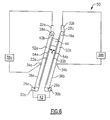
- FIG. 5 schematically illustrates a side view of a third example of a lateral sensor
- FIG. 6 schematically illustrates a side view of a grill employing the lateral sensor of the present invention.
- FIGS. 1 and 2 schematically illustrate a conveyor belt system 20 .
- the system 20 includes a conveyor belt 22 which travels around a structure 24 , a drive pulley 26 , and an opposing non-drive pulley 28 .
- a drive motor 30 drives the drive pulley 26 to move the conveyor belt 22 over the structure 24 .
- the non-drive pulley 28 is controlled by an adjustment motor 32 . Although only two pulleys 26 and 28 have been illustrated and disclosed, it is to be understood that additionally pulleys 26 and 28 can be employed in the conveyor belt system 20 .
- the conveyor belt 22 may move laterally in the directions A or B (i.e, right or left, respectively, as shown in FIG. 2 ) and slide off of the pulleys 26 and 28 .
- Lateral sensors 34 and 35 positioned proximate to each of the respective edges 36 and 37 of the conveyor belt 22 continually monitor the position of the edges 36 and 37 . If lateral movement is detected by the lateral sensor 34 or 35 , a controller 38 sends a signal to the adjustment motor 32 to move an end 40 of the non-drive pulley 28 to adjust for the lateral movement.
- the lateral sensors 34 or 35 in one example is a non-contacting inductive proximity sensor.
- the adjustment motor 32 rotates to move the end 40 of the non-drive pulley 28 to return the conveyor belt 22 to the desired position.
- the lateral sensor 35 does not sense the edge 37 of the conveyor belt 22 .
- the controller 38 then sends a signal to the adjustment motor 32 which rotates to raise the end 40 of the non-drive pulley 28 and move the conveyor belt 22 in the direction B (i.e., to the left in FIG. 2 ).
- the lateral sensor 35 again tries to detect the presence of the edge 37 of the conveyor belt 22 . If the edge 37 of the conveyor belt 22 is detected, no further adjustment is needed. If the edge 37 of the conveyor belt 22 is not detected, the adjustment motor 32 rotates again to raise the end 40 of the non-drive pulley 28 to again move the conveyor belt 22 in the direction B. This is repeated until the conveyor belt 22 is detected by the sensor 35
- the lateral sensor 34 does not sense the edge 36 of the conveyor belt 22 .
- the controller 38 then sends a signal to the adjustment motor 32 which rotates to lower the end 40 of the non-drive pulley 28 and move the conveyor belt 22 in the direction A (i.e., to the direction right in FIG. 2 ).
- the lateral sensor 34 again tries to detect the presence of the edge 36 of the conveyor belt 22 . If the edge 36 of the conveyor belt 22 is detected, no further adjustment is needed.
- the adjustment motor 32 rotates again to lower the end 40 of the non-drive pulley 28 to again move the conveyor belt 22 in the direction A. This is repeated until the edge 36 of the conveyor belt 22 is detected by the sensor 34 in the desired location.
- FIGS. 3 and 4 illustrate a second example of a lateral sensor 134 .
- the lateral sensor 134 includes a proportional sensor 136 , such as a linear variable displacement transducer or a linear potentiometer, having a shaft 138 .
- a spring 140 is positioned between a pair of washers 142 a and 142 b on the shaft 138 and provides resistance to a yoke 144 .
- a rotatable wheel 146 having a groove 148 is secured to the yoke 144 by a rod 150 .
- the rotatable wheel 146 is 1 ⁇ 2 inch in diameter and has a thickness of 1 ⁇ 8 inch to accommodate the conveyor belt 22 dimensions.
- the groove 148 contacts the edge 36 the conveyor belt 22 .
- the proportional sensor 136 determines if the edge 36 of the conveyor belt 22 has moved laterally by monitoring the resistance in the spring 140 . If the edge 36 of the conveyor belt 22 moves in the direction A, the yoke 144 responsively compresses the spring 140 , increasing the resistance In the spring 140 .
- the controller 38 receives a corresponding indication from the proportional sensor 136 and responsively sends a signal to the adjustment motor 32 , to raise the end 40 of the non-drive pulley 28 and laterally adjust the conveyor belt 22 a proportional amount in the direction B.
- the yoke 144 responsively expands the spring 140 , decreasing the resistance in the spring 140 .
- the controller 38 receives a corresponding indication from the proportional sensor 136 and responsively sends a signal to the adjustment motor 32 to lower the end 40 of the non-drive pulley 28 and laterally adjust the conveyor belt 22 a proportional amount in the direction A.
- the axis of the spring 140 is substantially perpendicular to the direction of movement of the conveyor belt 22 .
- the proportional sensor 136 determines if the edge 36 of the conveyor belt 22 has moved laterally by monitoring the resistance in the spring 140 . If the edge 36 of the conveyor belt 22 moves in the direction A, the yoke 144 responsively compresses the sprig 140 , increasing the resistance in the spring 140 . The controller 38 receives a corresponding indication from the proportion sensor 136 and responsively sends a signal to the adjustment motor 32 to raise the end 40 of the non-drive pulley 28 and laterally adjust the conveyor belt 22 a proportional amount in the direction B. Alternatively, if the edge 36 of the conveyor belt 22 moves in the direction B, the yoke 144 responsively expands the spring 140 , decreasing the resistance in the spring 140 . The controller 38 receives a corresponding indication from the proportional sensor 136 and responsively sends a signal to the adjustment motor 38 to lower the end 40 of the non-drive pulley 28 and laterally adjust the conveyor belt 22 a proportional amount in the direction A.
- FIG. 6 illustrates a schematic example of a grilling component 50 including two conveyor belts 22 a and 22 b which cooks food items 44 .
- the grilling component 50 includes a pair of grilling structures 52 a and 52 b separated by a gap d.
- Each respective grilling structure 52 a and 52 b includes a heater 54 a and 54 b , a drive pulley 26 a and 26 b , and a non-drive pulley 28 a and 28 b .
- a conveyor belt 22 a and 22 b is positioned around each of the grilling structures 52 a and 52 b .
- the heater 54 a and 54 b in one example grill is at a temperature of 400° F.
- the drive pulleys 26 a and 26 b are powered by respective drive motors 30 a and 30 b to move the conveyor belts 22 a and 22 b , creating a surface that travels over the heaters 54 a and 54 b .
- the non-drive pulleys 28 a and 28 b are each controlled by a respective adjustment motor 32 a and 32 b .
- a drive controller 42 provides a control signal to the drive motors 30 a and 30 b to synchronize the speed of the conveyor belts 22 a and 22 b . As the food items 44 travel in the gap d between the conveyor belts 22 a and 22 b , the food items 44 are grilled by the heater 54 a and 54 b under the conveyor belts 22 a and 22 b.
- a lateral sensor 34 a and 34 b is positioned proximate to the respective edges 36 a and 36 b of the conveyor belts 22 a and 22 b to continually monitor the position of the edges 36 a and 36 b .
- a controller 38 a sends a signal to the adjustment motor 32 a .
- the adjustment motors 32 a rotates to lower the end 40 a of the non-drive pulley 28 a to return the conveyor belt 22 a to the desired position.
- a controller 38 b sends a signal to the adjustment motor 32 b .
- the adjustment motors 32 b rotates to lower the end 40 b of the non-drive pulley 28 b to return the conveyor belt 22 b to the desired position.
- a lateral sensor (not shown) can also be positioned on the opposite edge (not shown) of the conveyor belts 22 a and 22 b to detect lateral movement in the opposing lateral direction (i.e., out of the page in FIG. 6 ).
- the lateral sensor of the present invention can be used with an automated grill, such as described in co-pending patent application Ser. No. 10/24629 entitled “Automated grill” filed on Apr. 17, 1802.
Abstract
Description
Claims (9)
Priority Applications (3)
| Application Number | Priority Date | Filing Date | Title |
|---|---|---|---|
| US10/124,622 US6852050B2 (en) | 2002-04-17 | 2002-04-17 | Lateral sensor for conveyor belt |
| PCT/US2003/006890 WO2003089343A1 (en) | 2002-04-17 | 2003-03-06 | Lateral sensor for conveyor belt |
| AU2003220062A AU2003220062A1 (en) | 2002-04-17 | 2003-03-06 | Lateral sensor for conveyor belt |
Applications Claiming Priority (1)
| Application Number | Priority Date | Filing Date | Title |
|---|---|---|---|
| US10/124,622 US6852050B2 (en) | 2002-04-17 | 2002-04-17 | Lateral sensor for conveyor belt |
Publications (2)
| Publication Number | Publication Date |
|---|---|
| US20030199349A1 US20030199349A1 (en) | 2003-10-23 |
| US6852050B2 true US6852050B2 (en) | 2005-02-08 |
Family
ID=29214622
Family Applications (1)
| Application Number | Title | Priority Date | Filing Date |
|---|---|---|---|
| US10/124,622 Expired - Fee Related US6852050B2 (en) | 2002-04-17 | 2002-04-17 | Lateral sensor for conveyor belt |
Country Status (3)
| Country | Link |
|---|---|
| US (1) | US6852050B2 (en) |
| AU (1) | AU2003220062A1 (en) |
| WO (1) | WO2003089343A1 (en) |
Cited By (10)
| Publication number | Priority date | Publication date | Assignee | Title |
|---|---|---|---|---|
| WO2009092130A1 (en) * | 2008-01-22 | 2009-07-30 | Barge's Belting Solution Pty Ltd | Method and apparatus for monitoring a conveyor belt |
| US20100230248A1 (en) * | 2008-11-17 | 2010-09-16 | Kouichi Kimura | Belt device and fixing device |
| US20110066291A1 (en) * | 2008-05-28 | 2011-03-17 | Kabushiki Kaisha Kobe Seiko Sho (Kobe Steel, Ltd.) | Belt meandering preventing device and belt meandering preventing method for running test device |
| US8657105B2 (en) | 2008-09-19 | 2014-02-25 | Fenner Dunlop Americas, Inc. | System and method for controlling a conveyor belt condition monitoring system |
| US9528576B2 (en) * | 2015-04-14 | 2016-12-27 | Deere & Company | Drive system with hydraulic idler tensioner |
| US9546046B2 (en) * | 2015-05-14 | 2017-01-17 | James O'Brien | Apparatus for conveyor belt tracking |
| WO2020023499A1 (en) | 2018-07-25 | 2020-01-30 | Gates Corporation | Belt sensor system |
| US10729965B2 (en) * | 2017-12-22 | 2020-08-04 | Icon Health & Fitness, Inc. | Audible belt guide in a treadmill |
| US11150151B2 (en) * | 2018-12-19 | 2021-10-19 | Otis Elevator Company | Method and device for monitoring chain tension |
| US11155416B2 (en) * | 2019-05-08 | 2021-10-26 | Rcs Technologies Llc | Conveyor belt monitoring system and method |
Families Citing this family (11)
| Publication number | Priority date | Publication date | Assignee | Title |
|---|---|---|---|---|
| WO2007011402A2 (en) * | 2004-10-26 | 2007-01-25 | Georgia Tech Research Corporation | Displacement sensor |
| US20090058430A1 (en) * | 2007-09-05 | 2009-03-05 | Sentrinsic | Systems and Methods for Sensing Positions of Components |
| US20090090603A1 (en) | 2007-10-04 | 2009-04-09 | Acrison, Inc. | Automatic Belt Tracking System |
| US7794605B2 (en) * | 2008-06-19 | 2010-09-14 | Flsmidth A/S | Horizontal belt filter with vacuum pan alignment |
| DE102015224337A1 (en) * | 2015-12-04 | 2017-06-08 | Lenze Automation Gmbh | Electric drive system |
| DE102017126569A1 (en) * | 2017-11-13 | 2019-05-16 | Sick Ag | Sensor arrangement for determining a variable voltage of a circulating chain or belt drive |
| US10850948B2 (en) | 2018-09-12 | 2020-12-01 | Otis Elevator Company | Escalator with a sensor for detecting sheave misalignment |
| FR3093091B1 (en) * | 2019-02-25 | 2021-06-11 | Procys | U-shaped accumulator for transferring small objects, especially food items |
| JP7277297B2 (en) * | 2019-07-11 | 2023-05-18 | ファナック株式会社 | Power transmission devices and industrial machinery |
| DE102020128355A1 (en) * | 2020-05-26 | 2021-12-02 | Aktiebolaget Skf | Belt tension monitoring device |
| IT202100007355A1 (en) * | 2021-03-25 | 2022-09-25 | Scm Group Spa | MACHINE WITH IMPROVED CONVEYOR SYSTEM. |
Citations (16)
| Publication number | Priority date | Publication date | Assignee | Title |
|---|---|---|---|---|
| US3545599A (en) | 1968-03-15 | 1970-12-08 | Barber Greene Co | Automatic belt centering method and apparatus |
| US3621987A (en) | 1968-09-05 | 1971-11-23 | Grace W R & Co | System for guiding the travel of a belt supported by a rotary drum |
| DE2010236A1 (en) | 1969-03-07 | 1973-03-22 | British Aircraft Corp Ltd | PIVOT AXLE ASSEMBLY OF A PIVOT WING AIRPLANE |
| US4959040A (en) * | 1989-04-21 | 1990-09-25 | Rastergraphics Inc. | Method and apparatus for precisely positioning and stabilizing a continuous belt or web or the like |
| US4961089A (en) | 1988-12-27 | 1990-10-02 | Eastman Kodak Company | Method and apparatus for web tracking with predictive control |
| US5153655A (en) * | 1990-01-11 | 1992-10-06 | Canon Kabushiki Kaisha | Lateral shift control for endless belt and fixing apparatus using same |
| US5157444A (en) * | 1990-01-11 | 1992-10-20 | Canon Kabushiki Kaisha | Apparatus for controlling the lateral shifting of an endless belt by detecting belt position |
| US5316524A (en) * | 1992-12-28 | 1994-05-31 | Xerox Corporation | Edge guide systems for belt tracking |
| US5394222A (en) * | 1993-12-17 | 1995-02-28 | Xerox Corporation | Correction of misalignment in a multicolor imaging apparatus utilizing a conformable friction drive system |
| US5515139A (en) | 1994-08-29 | 1996-05-07 | Xerox Corporation | Apparatus and method for lateral belt control with backlash compensation |
| US5630358A (en) * | 1994-11-14 | 1997-05-20 | Patel; Chandulal | Countertop appliance for making disc-shaped edibles |
| US5838359A (en) * | 1997-03-05 | 1998-11-17 | Xerox Corporation | Interpolated reference for improved digital feedback control regulation |
| US5964339A (en) * | 1995-12-12 | 1999-10-12 | Minolta Co., Ltd. | Apparatus for detecting a transverse movement of an endless belt |
| EP0989079A1 (en) | 1998-09-10 | 2000-03-29 | Bernhard Beumer Maschinenfabrik KG | Control system for the (straight) running of an elongate traction means, especially a transport belt |
| US6141525A (en) * | 1995-04-28 | 2000-10-31 | Canon Kabushiki Kaisha | Image forming apparatus having correction device for lateral misalignment |
| US6575857B2 (en) * | 2001-05-01 | 2003-06-10 | Sebright Products, Inc. | Automatic belt positioning assembly |
Family Cites Families (1)
| Publication number | Priority date | Publication date | Assignee | Title |
|---|---|---|---|---|
| DE20102365U1 (en) * | 2001-02-08 | 2001-06-21 | Horstmann Valentin | Device for regulating a conveyor belt in a conveyor belt system |
-
2002
- 2002-04-17 US US10/124,622 patent/US6852050B2/en not_active Expired - Fee Related
-
2003
- 2003-03-06 WO PCT/US2003/006890 patent/WO2003089343A1/en not_active Application Discontinuation
- 2003-03-06 AU AU2003220062A patent/AU2003220062A1/en not_active Abandoned
Patent Citations (16)
| Publication number | Priority date | Publication date | Assignee | Title |
|---|---|---|---|---|
| US3545599A (en) | 1968-03-15 | 1970-12-08 | Barber Greene Co | Automatic belt centering method and apparatus |
| US3621987A (en) | 1968-09-05 | 1971-11-23 | Grace W R & Co | System for guiding the travel of a belt supported by a rotary drum |
| DE2010236A1 (en) | 1969-03-07 | 1973-03-22 | British Aircraft Corp Ltd | PIVOT AXLE ASSEMBLY OF A PIVOT WING AIRPLANE |
| US4961089A (en) | 1988-12-27 | 1990-10-02 | Eastman Kodak Company | Method and apparatus for web tracking with predictive control |
| US4959040A (en) * | 1989-04-21 | 1990-09-25 | Rastergraphics Inc. | Method and apparatus for precisely positioning and stabilizing a continuous belt or web or the like |
| US5153655A (en) * | 1990-01-11 | 1992-10-06 | Canon Kabushiki Kaisha | Lateral shift control for endless belt and fixing apparatus using same |
| US5157444A (en) * | 1990-01-11 | 1992-10-20 | Canon Kabushiki Kaisha | Apparatus for controlling the lateral shifting of an endless belt by detecting belt position |
| US5316524A (en) * | 1992-12-28 | 1994-05-31 | Xerox Corporation | Edge guide systems for belt tracking |
| US5394222A (en) * | 1993-12-17 | 1995-02-28 | Xerox Corporation | Correction of misalignment in a multicolor imaging apparatus utilizing a conformable friction drive system |
| US5515139A (en) | 1994-08-29 | 1996-05-07 | Xerox Corporation | Apparatus and method for lateral belt control with backlash compensation |
| US5630358A (en) * | 1994-11-14 | 1997-05-20 | Patel; Chandulal | Countertop appliance for making disc-shaped edibles |
| US6141525A (en) * | 1995-04-28 | 2000-10-31 | Canon Kabushiki Kaisha | Image forming apparatus having correction device for lateral misalignment |
| US5964339A (en) * | 1995-12-12 | 1999-10-12 | Minolta Co., Ltd. | Apparatus for detecting a transverse movement of an endless belt |
| US5838359A (en) * | 1997-03-05 | 1998-11-17 | Xerox Corporation | Interpolated reference for improved digital feedback control regulation |
| EP0989079A1 (en) | 1998-09-10 | 2000-03-29 | Bernhard Beumer Maschinenfabrik KG | Control system for the (straight) running of an elongate traction means, especially a transport belt |
| US6575857B2 (en) * | 2001-05-01 | 2003-06-10 | Sebright Products, Inc. | Automatic belt positioning assembly |
Non-Patent Citations (1)
| Title |
|---|
| International Search Report dated Aug. 5, 2003. |
Cited By (18)
| Publication number | Priority date | Publication date | Assignee | Title |
|---|---|---|---|---|
| US20100294624A1 (en) * | 2008-01-22 | 2010-11-25 | Barge's Belting Solution Pty Ltd | Method and apparatus for monitoring a conveyor belt |
| WO2009092130A1 (en) * | 2008-01-22 | 2009-07-30 | Barge's Belting Solution Pty Ltd | Method and apparatus for monitoring a conveyor belt |
| AU2009206205B2 (en) * | 2008-01-22 | 2011-08-11 | Barge's Belting Solution Pty Ltd | Method and apparatus for monitoring a conveyor belt |
| US8127918B2 (en) | 2008-01-22 | 2012-03-06 | Barge's Belting Solution Pty Ltd | Method and apparatus for monitoring a conveyor belt |
| US20110066291A1 (en) * | 2008-05-28 | 2011-03-17 | Kabushiki Kaisha Kobe Seiko Sho (Kobe Steel, Ltd.) | Belt meandering preventing device and belt meandering preventing method for running test device |
| US8381902B2 (en) * | 2008-05-28 | 2013-02-26 | Kobe Steel, Ltd. | Belt meandering preventing device and belt meandering preventing method for running test device |
| US8657105B2 (en) | 2008-09-19 | 2014-02-25 | Fenner Dunlop Americas, Inc. | System and method for controlling a conveyor belt condition monitoring system |
| US8662290B2 (en) | 2008-09-19 | 2014-03-04 | Fenner Dunlop Americas, Inc. | Conveyor belt condition monitoring system |
| US7987971B2 (en) * | 2008-11-17 | 2011-08-02 | Fuji Xerox Co., Ltd. | Belt device and fixing device |
| US20100230248A1 (en) * | 2008-11-17 | 2010-09-16 | Kouichi Kimura | Belt device and fixing device |
| US9528576B2 (en) * | 2015-04-14 | 2016-12-27 | Deere & Company | Drive system with hydraulic idler tensioner |
| US9995374B2 (en) | 2015-04-14 | 2018-06-12 | Deere & Company | Drive system with hydraulic idler tensioner |
| US9546046B2 (en) * | 2015-05-14 | 2017-01-17 | James O'Brien | Apparatus for conveyor belt tracking |
| US10729965B2 (en) * | 2017-12-22 | 2020-08-04 | Icon Health & Fitness, Inc. | Audible belt guide in a treadmill |
| WO2020023499A1 (en) | 2018-07-25 | 2020-01-30 | Gates Corporation | Belt sensor system |
| US11105401B2 (en) | 2018-07-25 | 2021-08-31 | Gates Corporation | Belt sensor system |
| US11150151B2 (en) * | 2018-12-19 | 2021-10-19 | Otis Elevator Company | Method and device for monitoring chain tension |
| US11155416B2 (en) * | 2019-05-08 | 2021-10-26 | Rcs Technologies Llc | Conveyor belt monitoring system and method |
Also Published As
| Publication number | Publication date |
|---|---|
| AU2003220062A1 (en) | 2003-11-03 |
| WO2003089343A1 (en) | 2003-10-30 |
| US20030199349A1 (en) | 2003-10-23 |
Similar Documents
| Publication | Publication Date | Title |
|---|---|---|
| US6852050B2 (en) | Lateral sensor for conveyor belt | |
| US8234972B2 (en) | Automated grill | |
| US20170303739A1 (en) | Two-Surface Grill With Adjustable Gap and Multi-Stage Method For Cooking Food | |
| US3646880A (en) | Cooking grill | |
| US6624396B2 (en) | Conveyor speed control system for a conveyor oven | |
| US4565704A (en) | Method and apparatus for frying | |
| US20060237422A1 (en) | Grilling component | |
| US20210244234A1 (en) | Grilling appliance with lower platen position control | |
| US6717111B2 (en) | Grilling component | |
| CA2319797A1 (en) | Contact toaster with infinite adjustment | |
| US20050229919A1 (en) | Heated holding compartment for food | |
| US20180317709A1 (en) | Conveyor speed control system | |
| US7059467B2 (en) | Conveyor belt assembly | |
| JP3932953B2 (en) | Heat stabilization device in heating device | |
| CN211511519U (en) | Beefsteak roasting machine | |
| RU2048145C1 (en) | Device for roasting food | |
| AU7341194A (en) | Cooking arrangements |
Legal Events
| Date | Code | Title | Description |
|---|---|---|---|
| AS | Assignment |
Owner name: CARRIER COMMERCIAL REFRIGERATION, NEW YORK Free format text: ASSIGNMENT OF ASSIGNORS INTEREST;ASSIGNORS:SANDS, JEFFREY L.;GLAVEN, RONALD J.;REEL/FRAME:013124/0495 Effective date: 20020613 |
|
| AS | Assignment |
Owner name: CARRIER COMMERCIAL REFRIGERATION, INC., NEW YORK Free format text: CORRECTIVE ASSIGNMENT TO CORRECT THE NAME OF THE ASSIGNEE FILED ON 07/22/02, RECORDED ON REEL 013124 FRAME 0495;ASSIGNORS:SANDS, JEFFREY L.;GLAVEN, RONALD J.;REEL/FRAME:014076/0872 Effective date: 20020613 |
|
| CC | Certificate of correction | ||
| AS | Assignment |
Owner name: MCDONALD'S CORPORATION, ILLINOIS Free format text: ASSIGNMENT OF ASSIGNORS INTEREST;ASSIGNOR:CARRIER COMMERCIAL REFRIGERATION, INC.;REEL/FRAME:017275/0348 Effective date: 20050816 |
|
| FPAY | Fee payment |
Year of fee payment: 4 |
|
| AS | Assignment |
Owner name: RESTAURANT TECHNOLOGY, INC., ILLINOIS Free format text: ASSIGNMENT OF ASSIGNORS INTEREST;ASSIGNOR:MCDONALD'S CORPORATION;REEL/FRAME:022562/0974 Effective date: 20090401 |
|
| REMI | Maintenance fee reminder mailed | ||
| LAPS | Lapse for failure to pay maintenance fees | ||
| STCH | Information on status: patent discontinuation |
Free format text: PATENT EXPIRED DUE TO NONPAYMENT OF MAINTENANCE FEES UNDER 37 CFR 1.362 |
|
| FP | Lapsed due to failure to pay maintenance fee |
Effective date: 20130208 |