US6868434B1 - System and method for testing server latencies using multiple concurrent users in a computer system - Google Patents
System and method for testing server latencies using multiple concurrent users in a computer system Download PDFInfo
- Publication number
- US6868434B1 US6868434B1 US09/633,476 US63347600A US6868434B1 US 6868434 B1 US6868434 B1 US 6868434B1 US 63347600 A US63347600 A US 63347600A US 6868434 B1 US6868434 B1 US 6868434B1
- Authority
- US
- United States
- Prior art keywords
- user
- server
- access
- directory
- instance
- Prior art date
- Legal status (The legal status is an assumption and is not a legal conclusion. Google has not performed a legal analysis and makes no representation as to the accuracy of the status listed.)
- Expired - Lifetime, expires
Links
Images


Classifications
-
- H—ELECTRICITY
- H04—ELECTRIC COMMUNICATION TECHNIQUE
- H04L—TRANSMISSION OF DIGITAL INFORMATION, e.g. TELEGRAPHIC COMMUNICATION
- H04L41/00—Arrangements for maintenance, administration or management of data switching networks, e.g. of packet switching networks
-
- H—ELECTRICITY
- H04—ELECTRIC COMMUNICATION TECHNIQUE
- H04L—TRANSMISSION OF DIGITAL INFORMATION, e.g. TELEGRAPHIC COMMUNICATION
- H04L43/00—Arrangements for monitoring or testing data switching networks
- H04L43/50—Testing arrangements
-
- H—ELECTRICITY
- H04—ELECTRIC COMMUNICATION TECHNIQUE
- H04L—TRANSMISSION OF DIGITAL INFORMATION, e.g. TELEGRAPHIC COMMUNICATION
- H04L41/00—Arrangements for maintenance, administration or management of data switching networks, e.g. of packet switching networks
- H04L41/50—Network service management, e.g. ensuring proper service fulfilment according to agreements
- H04L41/5003—Managing SLA; Interaction between SLA and QoS
- H04L41/5009—Determining service level performance parameters or violations of service level contracts, e.g. violations of agreed response time or mean time between failures [MTBF]
Definitions
- This invention relates generally to the field of computer systems and, more particularly, to testing server latencies in computer systems.
- Computer systems may include multiple clients coupled to a server.
- a server may be configured to store information such that the information may be accessed by multiple users using one of the clients.
- a server may operate using an operating system such as Solaris, Linux, Windows 2000, or Windows NT.
- An operating system may be configured to create users that may access files on the server. These users may be given varying access privileges to information on the server and may be included in a group where each member of the group may be given a predefined set of access privileges within the system.
- the tasks of a server or more particularly, the operating system operating on the server may include creating and deleting users, logging in and logging out users, performing accesses to files on the server on behalf of users, and possibly executing applications or other programs on the server.
- the latency in performing a given task may increase as the task may not be completed until busy resources within the server become available. It would be desirable to measure server latencies in a system with multiple users. It would further be desirable to measure server latencies in a system with multiple users where the users are modeled according to an organization profile. A system and method to broadly measure server latencies is needed.
- a computer system may include a server and one or more clients. Multiple users may be created in the system such that each user may login to the server.
- the server may include a directory for each user and the directory for each user may be populated with a mix of files according to a user type for each user. An instance of a test program may be executed for each user on one or more clients concurrently.
- the server may authenticate each user using the same or different operating system protocols.
- Each instance of the test program may be configured to cause a series of accesses to one or more files in the directory of its respective user on the server and may be configured to cause a latency value to be measured and stored for each access that is performed.
- the latency values may be compiled by each instance of the test program and may be stored onto the server upon completion of each instance of the test program.
- the latency values measured by an instance of the test program may represent a first time portion that corresponds to the amount of time to perform a given access and a second time portion that corresponds to the server verifying that the user corresponding to this instance of the test program has permission to access the file.
- the accesses performed may include read accesses or write accesses.
- a setup program may be configured to create multiple users on a server in a computer system.
- the setup program may also be configured to create home directories for each user on the server and may further be configured to populate the home directory of each user with a mix of files that corresponds to the user type of each user.
- a test script may be initiated.
- the test script may be configured to coordinate the concurrent execution of instances of a test program for a set of users in the system.
- the test script may cause each client in the system to be reset, may cause a system clock to be synchronized, may cause a directory share to be created, and may cause an instance of a test program to be initiated for each of a set of users.
- Each instance of a test program may generate and store values that may be analyzed in accordance with the type of test being performed.
- a test program may be configured to generate and store latency values associated with accesses to files on the server in the system.
- a server may authenticate a user corresponding to the test program and may provide a token that may be used by the test program to access files on the server.
- the test program may cause files within the directory structure of the user to be enumerated into a table and may cause an order of these files to generated according to a seed value using a random number generator.
- the test program may then cause read and write accesses to the files in the order generated by the random number generator.
- the test program may store a latency value associated with each access. Each successive access may be made to the same file as a previous access or to a different file as the previous access.
- a file When a file is first accessed, it may be opened on the server and the server may verify that the user associated with the test program has permission to perform an access to the file using the token. The time taken by the server to perform the verification may be reflected in the latency value stored by the test program.
- FIG. 1 is a block diagram illustrating one embodiment of a computer system configured to test server latencies using multiple concurrent users.
- FIG. 2 is a flow chart illustrating a method for testing server latencies using multiple concurrent users.
- FIG. 3 is a flow chart illustrating a method for setting up a test environment.
- FIG. 4 a is a diagram illustrating a directory structure.
- FIG. 4 b is a diagram illustrating one example of populating a directory structure.
- FIG. 5 is a table illustrating attributes of different user types for an example organization.
- FIG. 6 is a diagram illustrating an example of populating the directory structures of multiple users.
- FIG. 7 is a flow chart illustrating a method for concurrently executing instances of a test program.
- FIG. 8 a is a flow chart illustrating a method for initiating instances of a test program.
- FIG. 8 b is a first portion of a flow chart illustrating a method for testing server latencies.
- FIG. 8 c is a second portion of a flow chart illustrating a method for testing server latencies.
- FIG. 9 a is a table illustrating an example of a directory enumeration table.
- FIG. 9 b is a table illustrating an example ordering of a directory enumeration table using a first seed value.
- FIG. 9 c is a table illustrating an example ordering of a directory enumeration table using a second seed value.
- FIG. 10 is a block diagram illustrating one embodiment of permission checking structures that may be used by an operation system.
- FIG. 1 a block diagram illustrating one embodiment of a computer system configured to test server latencies using multiple concurrent users is shown.
- FIG. 1 depicts server 100 coupled to clients 120 a , 120 b , and 120 c through network 110 .
- Clients 120 a , 120 b , and 120 c may be configured to execute system processes 122 a , 122 b , and 122 c , respectively.
- System processes 122 a , 122 b , and 122 c may include operating system routines or other applications.
- Clients 120 a , 120 b , and 120 c may also be configured to concurrently execute user0 test program 124 a through user(m) test program 124 ( m ), user(m+1) test program 124 ( m+ 1 ) through user(n) test program 124 ( n ), and user(n+1) test program 124 ( n +1), respectively.
- Clients 120 a , 120 b , and 120 c are shown by way of example as other embodiments may include other numbers of clients coupled to server 100 . Clients 120 a , 120 b , and 120 c may also be configured to execute other types of programs. Clients 120 a , 120 b , and 120 c may be referred to individually as a client 120 or collectively as clients 120 . User0 test program 124 a through user(n+1) test program 124 ( n +1) may be referred to individually as a test program 124 or collectively as test programs 124 . Each test program 124 may also be referred to as an instance.
- FIG. 1 illustrates a system for testing server latencies using multiple concurrent users.
- Clients 120 may each be configured to concurrently execute one or more instances of a test program 124 on behalf of multiple users.
- Each user may be created on server 100 such that server 100 may login a user in response to that user attempting to access a file or other resource on server 100 .
- Server 100 may create a home directory for each user and the home directory for each user may be populated with a mix of files according to a user type for each user as described in more detail below.
- Each test program 124 may cause communications to take place with server 100 across network 110 .
- Server 100 may authenticate a user for each test program 124 using the same or different operating system protocols.
- each instance of test program 124 may be configured to cause a series of accesses to one or more files in the directory of its respective user on server 100 and may be configured to cause a latency value to be measured and stored for each access that is performed.
- the latency values may be compiled by each instance of test program 124 and may be stored onto server 100 upon completion of each instance of test program 124 .
- the latency values measured by an instance of test program 124 may represent a first time portion that corresponds to the amount of time to perform a given access and a second time portion that corresponds to server 100 verifying that the user corresponding to this instance of the test program has permission to access the file.
- the accesses performed may include read accesses or write accesses.
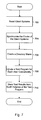
- FIG. 2 illustrates a method for testing server latencies using multiple concurrent users is shown. Variations on the method are possible and contemplated.
- Test setup actions may be performed as indicated in block 202 .
- Example test setup actions may include creating users, creating home directories for the users, and populating the home directories with files according to a user type of each user.
- Test programs may be concurrently executed using multiple users as indicated in block 204 .
- a test program may, for example, measure and store latencies associated with file accesses.
- One embodiment of a test program is described below with respect to FIGS. 8 b and 8 c .
- Test results generated by the test program may be stored as indicated in block 206 and the test results may be synthesized and analyzed as indicated in block 208 .
- Operating system attributes may be set as indicated in block 302 .
- the attributes set may depend on the type of operating system employed by a server such as server 100 shown in FIG. 1 .
- certain Advanced User Rights may be set to allow a user to impersonate another user.
- Windows NT may prevent a user from impersonating another user for security reasons. This security enforcement may be overcome by setting the following Advanced User Rights.
- users and user profiles may be created as indicated in block 304 and a home directory may be created for each user as indicated in block 306 .
- Users and corresponding user profiles may be created according to a user creation protocol of an operating system employed by a server.
- users may be created using the Security Accounts Manager (SAM) database of the Primary Domain Controller (PDC) in a Windows NT domain.
- SAM Security Accounts Manager
- PDC Primary Domain Controller
- ACL access control list for the home directory of each user may be set.
- users may be created using a CreateUsers program.
- the CreateUsers program may be executed on a client such as client 120 shown in FIG. 1 .
- the CreateUsers program may be used to create a specified number of users and may be executed using the following variables.
- Variable Explanation MINUSER First user number MAXUSER Number of users to create HOMEDIR Location of home directory on server for all users created HOMECOMPUTER Location of server (PDC) for all users created USER PREFIX Prefix added to user number to create user name USER POSTFIX Postfix added to user number to create user name For example, the following would create user1 to user500 in the current domain.
- the CreateUsers program may use a MakeUsr program to create users and create a profile for each user.
- the syntax of the MakeUsr program may be:
- Switch Explanation /DOMAIN Create a global user account in the domain versus a local user account on the local computer. (Default: local computer).
- /LOCAL local_group Add account to the specified local_group. Multiple /LOCAL switches may be allowed.
- a list of groups may be supplied in the MULOCAL command shell variable.
- /GLOBAL global_group Add account to the specified global_group. Multiple /GLOBAL switches may be allows.
- a list of groups may be supplied in the MUGLOBAL command shell variable.
- /FULLNAME name Specify full name for the account. Use quotes if the name contains spaces.
- /PROFILEPATH path Profile path for this account.
- /SCRIPTPATH path Logon script path for this account.
- /HOMEDIR path User home directory. If /HOMECOMPUTER is not specified, this may be a local path. If /HOMECOMPUTER is specified, this is a local path relative to that computer (e.g. C: refers to C: on that computer). /HOMECOMPUTER:name Computer to contain home directory. (Default: local computer). /HOMEPROTO:uncpath Unified naming convention (UNC) name of the prototype home directory. May be copied to the home directory when created. /COMMENT:text Text comment for this user name Additional options may be set up by initializing command shell variables prior to executing the MakeUsr program.
- a CleanUser program may be used to remove users from the SAM database of a PDC.
- the CleanUser program may use the following variables.
- Variable Explanation MINUSER First user number MAXUSER Last user number USER PREFIX Prefix added to user number to create user name USER POSTFIX Postfix added to user number to create user name For example, the following would delete user100 to user200 in the current domain.
- FIG. 4 a is a diagram illustrating generally the creation of a home directory for each user.
- home directories ⁇ user0 and ⁇ user1 through ⁇ user(n) where n represents the (n ⁇ 1)th user may be created in a directory named ⁇ users.
- the directory ⁇ users may be created anywhere within the directory structure of a server.
- the root directory of a server may be named ⁇ server and the dashed lines indicate paths to other directories within the directory structure.
- the directory ⁇ users may be directly under the root directory ⁇ server or any number of directories may be included between the root directory ⁇ server and the directory ⁇ users.
- each home directory may be populated according to a user type as indicated in block 308 .
- the home directory of each user may be populated with a set of files that corresponds to a user type for that user.
- a test program may be configured to perform accesses to these files.
- FIG. 4 b illustrates one example of a home directory populated with files and a directory structure.
- FIG. 4 b shows the directory of user(n), ⁇ user(n), populated with files f1, f2, f3, f4, f5, and f6 using directories ⁇ d1, ⁇ d2, ⁇ d3, ⁇ d4, ⁇ d5, and ⁇ d6 as shown.
- each file f1 through f6 may vary according to a user type for user(n).
- the directory structure i.e. the arrangement of directories ⁇ d1 through ⁇ d6, may vary according to a user type for user(n).
- Other home directories may be populated with other numbers and sizes of files as well as other directory structures.
- the concurrent execution of an instance of a test program by multiple users may simulate a user load of an organization on a server.
- Organizations may comprise different types and number of users that access different sizes and types of files on a server.
- the number and type of users of the organization may be created.
- Instances of a test program may cause accesses to files in each user's home directory on the server according to a user's user type to simulate a user load of the organization on a server.
- FIG. 5 is a table illustrating attributes of different user types of an example organization.
- FIG. 5 depicts users, file uses, file sizes, load rates, stress rates, and file load mixes for each user type.
- the example organization may include three user types: small, medium, and large.
- the file uses and sizes indicate the use and size of files typically accessed by each user type.
- the load rate indicates a network transfer rate for each user type under typical conditions.
- the stress rate indicates a network transfer rate for each user type under stressed, i.e. test, conditions.
- the file load mix indicates the percentage of each of three respective files sizes: small, medium, and large.
- the small file size may refer to files that are 1-2 kilobytes
- the medium file size may refer to files that are 20-80 kilobytes
- the large file size may refer to files that are 0.5 to 2 megabytes.
- Small users Users in the organization that correspond to the small user type, “small users”, may be clerks such as sales assistants, inventory and stock clerks, and accounting clerks.
- the typical files accessed on a server by small users may be transaction records that are 1-2 kilobytes in size. Small users may have a load rate of 1 megabyte per hour and a stress rate of 6.7 megabytes per hour. Small users may access small files 70% of the time, medium files 20% of the time, and large files 10% of the time.
- Medium users Users in the organization that correspond to the medium user type, “medium users”, may be managers, secretarial workers, and administrative workers. Administrative workers may include human resource representatives, marketing personnel, and executives.
- the typical files accessed on a server by medium users may be memos and letters that are 20-80 kilobytes in size.
- Medium users may have a load rate of 1.5 megabytes per hour and a stress rate of 10 megabytes per hour.
- Medium users may access small files 10% of the time, medium files 70% of the time, and large files 20% of the time.
- Users in the organization that correspond to the large user type, “large users”, may be technical and creative workers such as engineers, programmers, graphic and mechanical designers, and architects.
- the typical files accessed on a server by large users may be design files that are 0.5 to 2 megabytes in size. Large users may have a load rate of 1 megabyte per hour and a stress rate of 6.7 megabytes per hour. Large users may access small files 10% of the time, medium files 20% of the time, and large files 70% of the time.
- the percentage of read accesses versus write accesses may be set by a test program, the default percentage may be set to 80% read accesses and 20% write accesses for each of the user types shown in FIG. 5 .
- an organization may be readily modeled using the above user types.
- the organization is an equipment supplier that designs, markets, and sells its own products
- the personnel and the correspond user of types may be modeled as follows.
- FIG. 6 a diagram illustrating an example of populating the directory structures of multiple users is shown.
- user home directories ⁇ user0, ⁇ user1, and ⁇ user2 may be created in a directory named ⁇ users.
- the directory ⁇ users may be created anywhere within the directory structure of a server.
- the root directory of a server may be named ⁇ server and the dashed lines indicate paths to other directories within the directory structure.
- the directory ⁇ users may be directly under the root directory ⁇ server or any number of directories may be included between the root directory ⁇ server and the directory ⁇ users.
- the directory ⁇ filemix may be directly under the root directory ⁇ server or any number of directories may be included between the root directory ⁇ server and the directory ⁇ filemix.
- the directory ⁇ filemix may include the directories ⁇ small, ⁇ medium, and ⁇ large.
- the directory ⁇ small may include directory structure 602
- the directory ⁇ medium may include directory structure 604
- the directory ⁇ large may include directory structure 606 .
- Each directory structure 602 , 604 , and 606 may include a set of subdirectories and files.
- Directory structures 602 , 604 , and 606 may each correspond to a different user type.
- directory structure 602 under the directory ⁇ small may correspond to a small user type such as the small user described above in FIG. 5 .
- directory structure 604 under the directory ⁇ medium may correspond to a medium user type such as the medium user described above in FIG.
- directory structure 606 under the directory ⁇ large may correspond to a large user type such as the large user described above in FIG. 5 .
- directory structures 602 , 604 , and 606 may include a mixture of files and directories appropriate for their respective user types.
- FIG. 6 illustrates a method of populating the home directories of a plurality of users.
- user0 may correspond to a large user type
- user1 may correspond to a small user type
- user2 may correspond to a medium user type.
- the directory structure corresponding to each user's user type may be copied from the appropriate directory under the directory ⁇ filemix.
- directory structure 606 may be copied to the directory ⁇ user0 to populate the home directory of user1.
- directory structure 602 may be copied to the directory ⁇ user1 to populate the home directory of user1 as illustrated by arrow 612
- directory structure 604 may be copied to the directory ⁇ user2 to populate the home directory of user2 as illustrated by arrow 614 .
- the method of populating a user's home directory shown in FIG. 6 illustrates one example of how a user's home directory may be populated. Numerous other methods are possible and contemplated. These other methods may include copying directory structures from a wider variety of user types that may have different file mixes than those described, generating directory structures for user types dynamically, or other methods that make files on a server available to a given user.
- a test script may perform the method described in FIG. 7 .
- Client systems may be reset as indicated in block 702 .
- the clocks of the client systems may be synchronized as indicated in block 704 .
- a directory share may be created as indicated in block 706 .
- a directory share may be used to indicate a directory location of the home directories of the users. For example, a directory share “m:” may be created to refer to the directory ⁇ users shown in FIG. 6.
- a test program may be initiated for each user concurrently as indicated in block 708 . Test results from each instance of the test program may be stored as indicated in block 710 .
- FIG. 8 a A flow chart illustrating a method for initiating instances of a test program as indicated in block 708 is shown in FIG. 8 a .
- An instance of a test program may be launched for a user as indicated in block 802 .
- a determination may be made as to whether an instance of the test program is to be launched for another user as indicated in block 804 . If an instance of the test program is to be launched for another user, then the function performed in block 802 may be repeated.
- FIGS. 8 b and 8 c a flow chart illustrating a method for testing server latencies is shown.
- Each instance of the test program referred to in FIG. 7 may be configured to perform the method described in FIGS. 8 b and 8 c .
- a user authentication may be performed according to an operating system protocol as indicated in block 806 .
- a user may be logged in to a server using an operating system protocol of a client.
- the operating system protocols may include a UNIX desktop login method, Windows NT 4.0 Workstation login method, or Windows 2000 Professional login method.
- the server may validate the logon of the user.
- An access token may be received as indicated in block 807 .
- the access token may be generated by the server and may be conveyed to the client that is executing the instance of the test program.
- FIGS. 9 a , 9 b , and 9 c illustrate an example of a directory enumeration table and examples of ordering a directory enumeration table using seed values.
- FIGS. 9 a , 9 b , and 9 c refer back to the directory structure shown in FIG. 4 b .
- Directory enumeration table 900 lists the files in the user's directory structure using the directory share created in block 706 of FIG. 7 .
- file 901 may be listed in directory enumeration table 900 as m: ⁇ d1 ⁇ d3 ⁇ f1.
- Files 902 through 906 may be listed similarly.
- a file order may be randomized using a seed for a random number generator as indicated in block 810 .
- an ordering 910 of directory enumeration table 900 may be created using seed value n shown in seed 912 .
- the seed value n of may be used by a random number generator to create ordering 910 such that the random number generator may create the same ordering 910 of files 901 through 906 each time the seed value n is used.
- the order created by using seed value n in FIG. 9 b is file 905 , file 903 , file 904 , file 902 , file 901 , and file 906 .
- FIG. 9 c illustrates ordering 920 where seed value n+1, shown in seed 922 , may be used.
- the order created by using seed value n+1 in FIG. 9 c , file 904 , file 902 , file 906 , file 905 , file 903 , and file 901 differs from that created by using seed value n in FIG. 9 b.
- the test program may be configured to access files (described below with respect to blocks 818 and 820 ) in the order created by the functions of blocks 808 and 810 . In this manner, the results of a test program may be replicated by using the same seed value.
- Blocks 812 and 814 indicate waiting for a start time to arrive before proceeding to block 816 .
- the use of a start time may allow the access performed by each instance of the test program to begin concurrently.
- the chart of FIG. 8 b may continue in FIG. 8 c as indicated by the circled A.
- FIG. 10 illustrates one embodiment of permission checking structures that may be used by an operation system to authorize the opening of a file.
- FIG. 10 depicts file 1010 with its corresponding file access control list (ACL) 1000 .
- File ACL 1000 may point to data structure 1020 that lists the permissions of each user to file 1010 .
- user0 has read permission as shown in entry 1022
- user1 has read and write permission as shown in entry 1024
- user2 has no permissions as shown in entry 1026
- user(n) has write permission as shown in entry 1028 .
- the server may reference file ACL 1000 to determine whether that user has permission to access file 1010 .
- a file may be opened as indicated in block 818 .
- a read or write access may be performed as indicated in block 820 .
- the latency to perform the read or write access may be measured as indicated in block 822 .
- the latency measurement may include the time to perform the file access as well as the time to authorize the opening of the file.
- the latency and access information may be stored as indicated in block 824 .
- the test program may attempt to transfer a specified amount of data within a specified amount of time. If the amount of data to be transferred is too great to be transferred during the time limit, then the test program may continue until all of the data is transferred.
- the amount of data to be read or written may be expressed as a ratio, where 1 is read only and 0 is write only. Thus, a ratio of 0.5 along with an amount of data to be transferred of 1 megabyte would indicate that the test program if to read 0.5 megabytes and write 0.5 megabytes.
- Each instance of test program may not operate continuously. Rather, each instance may be configured to start up at regular, specifiable intervals to perform a part of the total workload. This allows breaks between user activity. For example, the break between activities could be 1, 10, or 60 seconds.
- ReadRecordSize The size in bytes that records may be read from files.
- WriteRecordSize The size in bytes that records may be written to files. OnlyWriteAfter This parameter may be for write accesses only and may be specified in bytes. The parameter may define the maximum amount of data to be written to a file when a write operation is performed. This parameter may cause write accesses to be stored up until this number is exceeded and may allow for fast/auto save functions to be mimicked.
- WriteFileMinSize The minimum file size that may be created during write operations and may be specified in bytes.
- IOLimit The total amount of data to be transferred during the duration of the test. ReadRatio The proportion of the IOLimit that will be read accesses.
- the value may be between 1 and 0 where a value of 1 indicates 100% read accesses and a value of 0 indicates 100% write accesses. 0.8, for example, would indicate 80% read data transferred and 20% write data transferred.
- IODuration The time period over which a test may be performed and may be specified in minutes.
- IOTimeGranularity The regular time intervals where the test program may start up to perform an access. This parameter may be specified in milliseconds. If this parameter value is set too low, the test program may begin a second access prior to a first access completing.
- Seed The value used by the random number generator in creating an order of files to be accessed.
- StartDir The directory structure that the test program operates on. For example, m: ⁇ user0.
- ResultsDir The directory and filename where the results may be saved.
- Each instance of the test program may save its results in a separate file on the client in which it operates.
- the results may include the following fields for each access performed.
- Field Description Field 1 Descriptor for operation (e.g. read or write) Field 2 Time taken to transfer the data in milliseconds Field 3 Number of bytes read or written Field 4 Record size Field 5 Data and time stamp of operation The results may further include a summary line with the following fields.
- the results may be analyzed to determine how a server performed under a user load generated by the test program.
Abstract
Description
-
- 1. Act as part of the Operating System
- 2. Create a Token
- 3. Increase quotas
- 4. Replace a process-level token.
Once these Advanced User Rights are set, a server may support multiple users from a single client such as clients 120 shown inFIG. 1. A client 120 may use a token to launch multiple instances oftest program 124 for different users. Client 120 may do so by copying the token and including impersonate bits in the new token when launching an instance oftest program 124. In doing so, each instance oftest program 124 may be effectively executed by a different user andserver 100 may interact with each instance as though it were being executed by a different user.
| Variable | Explanation |
| MINUSER | First user number |
| MAXUSER | Number of users to create |
| HOMEDIR | Location of home directory on server for all users |
| created | |
| HOMECOMPUTER | Location of server (PDC) for all users created |
| USER PREFIX | Prefix added to user number to create user name |
| USER POSTFIX | Postfix added to user number to create user name |
For example, the following would create user1 to user500 in the current domain.
-
- set MINUSER=1
- set MAXUSERS=500
- set HOMEDIR=c:\export\home\users
- set HOMECOMPUTER=venom
- set USERPREFIX=user
- set USERPOSTFIX=createusers.
In this example, all users would be configured with \\venom\c$\export\home\users as the directory where their individual home directories would be created. The home directories would be named user0, user1, user2, . . . , user 499.
-
- makeusr user_name [password] [switches]
The switches for the MakeUsr program may include:
- makeusr user_name [password] [switches]
| Switch | Explanation |
| /DOMAIN | Create a global user account in the domain |
| versus a local user account on the local | |
| computer. (Default: local computer). | |
| /LOCAL:local_group | Add account to the specified local_group. |
| Multiple /LOCAL switches may be allowed. | |
| In addition, a list of groups may be supplied | |
| in the MULOCAL command shell variable. | |
| /GLOBAL:global_group | Add account to the specified global_group. |
| Multiple /GLOBAL switches may be allows. | |
| In addition, a list of groups may be supplied | |
| in the MUGLOBAL command shell variable. | |
| /FULLNAME:name | Specify full name for the account. Use |
| quotes if the name contains spaces. | |
| /PROFILEPATH:path | Profile path for this account. |
| /SCRIPTPATH:path | Logon script path for this account. |
| /HOMEDIR:path | User home directory. If |
| /HOMECOMPUTER is not specified, this | |
| may be a local path. If /HOMECOMPUTER | |
| is specified, this is a local path relative to | |
| that computer (e.g. C: refers to C: on | |
| that computer). | |
| /HOMECOMPUTER:name | Computer to contain home directory. |
| (Default: local computer). | |
| /HOMEPROTO:uncpath | Unified naming convention (UNC) name of |
| the prototype home directory. May be copied | |
| to the home directory when created. | |
| /COMMENT:text | Text comment for this user name |
Additional options may be set up by initializing command shell variables prior to executing the MakeUsr program.
| Variable | Explanation |
| MINUSER | First user number |
| MAXUSER | Last user number |
| USER PREFIX | Prefix added to user number to create user name |
| USER POSTFIX | Postfix added to user number to create user name |
For example, the following would delete user100 to user200 in the current domain.
-
- set MINUSER=100
- set MAXUSERS=200
- set USERPREFIX=user
- set USERPOSTFIX=cleanuser
| Department | Title | Number | User |
| Executive | President | ||
| 1 | | ||
| Vice-President | |||
| 1 | | ||
| Secretarial | |||
| 1 | Medium | ||
| Sales | Manager/ | 1 | Medium |
| | 10 | Small | |
| Outside Sales Representatives | 5 | | |
| Secretarial | |||
| 1 | Medium | ||
| Marketing | Manager/ | 1 | Medium |
| Marketing Specialists | 4 | | |
| Secretarial | |||
| 1 | Medium | ||
| Engineering | Manager/ | 1 | Large |
| Engineers/Technicians | 6 | | |
| Secretarial | |||
| 1 | Large | ||
| Finance/ | Manager/ | 1 | |
| Accounting | Accountant | ||
| 1 | Medium | ||
| Clerks | 3 | | |
| Secretarial | |||
| 1 | Medium | ||
| Warehouse/ | Manager/ | 1 | Medium |
| Shipping | Clerks | 8 | |
| Secretarial | |||
| 1 | Medium | ||
| Human | Manager/ | 1 | Medium |
| Resources | Human Resources Representatives | 3 | |
| Secretarial | |||
| 1 | Medium | ||
| Facilities | Manager/ | 1 | Medium |
| Maintenance Personnel | 3 | | |
| Secretarial | |||
| 1 | Medium | ||
The above organization results in the following numbers per user type.
| User Type | Number | ||
| Small | 24 | ||
| Medium | 28 | ||
| Large | 8 | ||
Loading ratios from the above numbers may be derived as follows.
Small:Medium:Large=24:28:8=3:3.5:1
This ratio represents the mix of small, medium, and large user types that may be presented to a server under test. This user mix may provide a distribution of file accesses that is representative of an actual system such as the system shown in FIG. 1.
| Parameter | Explanation |
| ReadRecordSize | The size in bytes that records may be read from |
| files. | |
| WriteRecordSize | The size in bytes that records may be written to |
| files. | |
| OnlyWriteAfter | This parameter may be for write accesses only and |
| may be specified in bytes. The parameter may | |
| define the maximum amount of data to be written to | |
| a file when a write operation is performed. This | |
| parameter may cause write accesses to be stored up | |
| until this number is exceeded and may allow for | |
| fast/auto save functions to be mimicked. | |
| WriteFileMinSize | The minimum file size that may be created during |
| write operations and may be specified in bytes. | |
| IOLimit | The total amount of data to be transferred during the |
| duration of the test. | |
| ReadRatio | The proportion of the IOLimit that will be read |
| accesses. The value may be between 1 and 0 where | |
| a value of 1 indicates 100% read accesses and a | |
| value of 0 indicates 100% write accesses. 0.8, for | |
| example, would indicate 80% read data transferred | |
| and 20% write data transferred. | |
| IODuration | The time period over which a test may be performed |
| and may be specified in minutes. | |
| IOTimeGranularity | The regular time intervals where the test program |
| may start up to perform an access. This parameter | |
| may be specified in milliseconds. If this parameter | |
| value is set too low, the test program may begin a | |
| second access prior to a first access completing. | |
| Seed | The value used by the random number generator in |
| creating an order of files to be accessed. | |
| StartDir | The directory structure that the test program |
| operates on. For example, m:\user0. | |
| ResultsDir | The directory and filename where the results may be |
| saved. | |
| | Description | ||
| Field | |||
| 1 | Descriptor for operation (e.g. read or write) | ||
| | Time taken to transfer the data in milliseconds | ||
| Field 3 | Number of bytes read or written | ||
| Field 4 | Record size | ||
| Field 5 | Data and time stamp of operation | ||
The results may further include a summary line with the following fields.
| | Description | ||
| Field | |||
| 1 | | ||
| Field | |||
| 2 | Total read time for test in seconds | ||
| Field 3 | Total bytes read during the test | ||
| Field 4 | Bytes read per second | ||
| Field 5 | Total number of files read | ||
| Field 6 | Total write time for test in seconds | ||
| Field 7 | Total bytes written during the test | ||
| Field 8 | Bytes written per second | ||
| Field 9 | Total number of files written | ||
Claims (20)
Priority Applications (1)
| Application Number | Priority Date | Filing Date | Title |
|---|---|---|---|
| US09/633,476 US6868434B1 (en) | 2000-08-07 | 2000-08-07 | System and method for testing server latencies using multiple concurrent users in a computer system |
Applications Claiming Priority (1)
| Application Number | Priority Date | Filing Date | Title |
|---|---|---|---|
| US09/633,476 US6868434B1 (en) | 2000-08-07 | 2000-08-07 | System and method for testing server latencies using multiple concurrent users in a computer system |
Publications (1)
| Publication Number | Publication Date |
|---|---|
| US6868434B1 true US6868434B1 (en) | 2005-03-15 |
Family
ID=34273239
Family Applications (1)
| Application Number | Title | Priority Date | Filing Date |
|---|---|---|---|
| US09/633,476 Expired - Lifetime US6868434B1 (en) | 2000-08-07 | 2000-08-07 | System and method for testing server latencies using multiple concurrent users in a computer system |
Country Status (1)
| Country | Link |
|---|---|
| US (1) | US6868434B1 (en) |
Cited By (14)
| Publication number | Priority date | Publication date | Assignee | Title |
|---|---|---|---|---|
| US20020199005A1 (en) * | 2001-03-16 | 2002-12-26 | Manfred Schneider | Development computer, development program for combining components to applications, using component descriptors related to the components, method, and computer program |
| US20020198982A1 (en) * | 2001-06-22 | 2002-12-26 | International Business Machines Corporation | Monitoring Tool |
| US20030060285A1 (en) * | 2001-08-30 | 2003-03-27 | Eisaburo Itakura | Network game system, network game server, and network game terminal |
| US20040117460A1 (en) * | 2002-12-13 | 2004-06-17 | Walsh Robert E. | Multi-user web simulator |
| US20040117170A1 (en) * | 2002-12-13 | 2004-06-17 | Walsh Robert E. | Web simulator |
| US20040193881A1 (en) * | 2003-03-26 | 2004-09-30 | Yasushi Ayaki | Data use management system, transmitting apparatus having management function, and data use management method |
| US20060136578A1 (en) * | 2004-12-16 | 2006-06-22 | Michele Covell | Monitoring the performance of a streaming media server using server-side and client-side measurements |
| US20060146722A1 (en) * | 2004-12-30 | 2006-07-06 | Jean-Francois Dube | Altering latency for network testing |
| US20070006177A1 (en) * | 2005-05-10 | 2007-01-04 | International Business Machines Corporation | Automatic generation of hybrid performance models |
| US20080102955A1 (en) * | 2006-10-25 | 2008-05-01 | D Amora Bruce D | System and apparatus for managing latency-sensitive interaction in virtual environments |
| WO2009086529A1 (en) * | 2007-12-29 | 2009-07-09 | Brigitte Bernadette Birze | System, method, and computer-readable medium for dynamic device discovery for servers binding to multiple masters |
| US20090182439A1 (en) * | 2004-09-09 | 2009-07-16 | Amx, Llc | System, method, and computer-readable medium for dynamic device discovery for servers binding to multiple masters |
| CN106850245A (en) * | 2015-12-07 | 2017-06-13 | 中兴通讯股份有限公司 | A kind of diagnostic test message treatment method and device |
| CN111309592A (en) * | 2020-01-14 | 2020-06-19 | 浙江省北大信息技术高等研究院 | Authority checking method and device, storage medium and terminal |
Citations (14)
| Publication number | Priority date | Publication date | Assignee | Title |
|---|---|---|---|---|
| US5355497A (en) * | 1992-06-10 | 1994-10-11 | Physiotronics Corporation | File directory structure generator and retrevial tool with document locator module mapping the directory structure of files to a real world hierarchical file structure |
| US5485606A (en) * | 1989-07-10 | 1996-01-16 | Conner Peripherals, Inc. | System and method for storing and retrieving files for archival purposes |
| US5838909A (en) | 1996-05-23 | 1998-11-17 | Sandcastle, Inc. | Reducing latency when synchronizing access to a multi-user database over a network |
| US5966162A (en) | 1996-10-25 | 1999-10-12 | Diva Systems Corporation | Method and apparatus for masking the effects of latency in an interactive information distribution system |
| US6138112A (en) * | 1998-05-14 | 2000-10-24 | Microsoft Corporation | Test generator for database management systems |
| US6154744A (en) * | 1995-06-07 | 2000-11-28 | Intervu, Inc. | System and method for optimized storage and retrieval of data on a distributed computer network |
| US6178419B1 (en) * | 1996-07-31 | 2001-01-23 | British Telecommunications Plc | Data access system |
| US6243832B1 (en) * | 1998-08-12 | 2001-06-05 | Bell Atlantic Network Services, Inc. | Network access server testing system and methodology |
| US6269401B1 (en) * | 1998-08-28 | 2001-07-31 | 3Com Corporation | Integrated computer system and network performance monitoring |
| US6321264B1 (en) * | 1998-08-28 | 2001-11-20 | 3Com Corporation | Network-performance statistics using end-node computer systems |
| US20020026321A1 (en) * | 1999-02-26 | 2002-02-28 | Sadeg M. Faris | Internet-based system and method for fairly and securely enabling timed-constrained competition using globally time-sychronized client subsystems and information servers having microsecond client-event resolution |
| US6415317B1 (en) | 1999-10-01 | 2002-07-02 | Joshua Michael Yelon | Software system for reducing the appearance of latency in a multi-user environment |
| US20020147969A1 (en) * | 1998-10-21 | 2002-10-10 | Richard A. Lethin | Dynamic optimizing object code translator for architecture emulation and dynamic optimizing object code translation method |
| US6560648B1 (en) * | 1999-04-19 | 2003-05-06 | International Business Machines Corporation | Method and apparatus for network latency performance measurement |
-
2000
- 2000-08-07 US US09/633,476 patent/US6868434B1/en not_active Expired - Lifetime
Patent Citations (14)
| Publication number | Priority date | Publication date | Assignee | Title |
|---|---|---|---|---|
| US5485606A (en) * | 1989-07-10 | 1996-01-16 | Conner Peripherals, Inc. | System and method for storing and retrieving files for archival purposes |
| US5355497A (en) * | 1992-06-10 | 1994-10-11 | Physiotronics Corporation | File directory structure generator and retrevial tool with document locator module mapping the directory structure of files to a real world hierarchical file structure |
| US6154744A (en) * | 1995-06-07 | 2000-11-28 | Intervu, Inc. | System and method for optimized storage and retrieval of data on a distributed computer network |
| US5838909A (en) | 1996-05-23 | 1998-11-17 | Sandcastle, Inc. | Reducing latency when synchronizing access to a multi-user database over a network |
| US6178419B1 (en) * | 1996-07-31 | 2001-01-23 | British Telecommunications Plc | Data access system |
| US5966162A (en) | 1996-10-25 | 1999-10-12 | Diva Systems Corporation | Method and apparatus for masking the effects of latency in an interactive information distribution system |
| US6138112A (en) * | 1998-05-14 | 2000-10-24 | Microsoft Corporation | Test generator for database management systems |
| US6243832B1 (en) * | 1998-08-12 | 2001-06-05 | Bell Atlantic Network Services, Inc. | Network access server testing system and methodology |
| US6269401B1 (en) * | 1998-08-28 | 2001-07-31 | 3Com Corporation | Integrated computer system and network performance monitoring |
| US6321264B1 (en) * | 1998-08-28 | 2001-11-20 | 3Com Corporation | Network-performance statistics using end-node computer systems |
| US20020147969A1 (en) * | 1998-10-21 | 2002-10-10 | Richard A. Lethin | Dynamic optimizing object code translator for architecture emulation and dynamic optimizing object code translation method |
| US20020026321A1 (en) * | 1999-02-26 | 2002-02-28 | Sadeg M. Faris | Internet-based system and method for fairly and securely enabling timed-constrained competition using globally time-sychronized client subsystems and information servers having microsecond client-event resolution |
| US6560648B1 (en) * | 1999-04-19 | 2003-05-06 | International Business Machines Corporation | Method and apparatus for network latency performance measurement |
| US6415317B1 (en) | 1999-10-01 | 2002-07-02 | Joshua Michael Yelon | Software system for reducing the appearance of latency in a multi-user environment |
Cited By (27)
| Publication number | Priority date | Publication date | Assignee | Title |
|---|---|---|---|---|
| US7100148B2 (en) * | 2001-03-16 | 2006-08-29 | Sap Ag | Development computer, development program for combining components to applications, using component descriptors related to the components, method, and computer program |
| US20020199005A1 (en) * | 2001-03-16 | 2002-12-26 | Manfred Schneider | Development computer, development program for combining components to applications, using component descriptors related to the components, method, and computer program |
| US20020198982A1 (en) * | 2001-06-22 | 2002-12-26 | International Business Machines Corporation | Monitoring Tool |
| US7149799B2 (en) * | 2001-06-22 | 2006-12-12 | International Business Machines Corporation | Monitoring tool |
| US20030060285A1 (en) * | 2001-08-30 | 2003-03-27 | Eisaburo Itakura | Network game system, network game server, and network game terminal |
| US8070603B2 (en) * | 2001-08-30 | 2011-12-06 | Sony Corporation | Network game system, network game server, and network game terminal |
| US20040117170A1 (en) * | 2002-12-13 | 2004-06-17 | Walsh Robert E. | Web simulator |
| US7143025B2 (en) | 2002-12-13 | 2006-11-28 | Sun Microsystems, Inc. | Web simulator |
| US7533012B2 (en) | 2002-12-13 | 2009-05-12 | Sun Microsystems, Inc. | Multi-user web simulator |
| US20040117460A1 (en) * | 2002-12-13 | 2004-06-17 | Walsh Robert E. | Multi-user web simulator |
| US20040193881A1 (en) * | 2003-03-26 | 2004-09-30 | Yasushi Ayaki | Data use management system, transmitting apparatus having management function, and data use management method |
| US7487351B2 (en) * | 2003-03-26 | 2009-02-03 | Panasonic Corporation | Data use management system, transmitting apparatus having management function, and data use management method |
| US8194660B2 (en) | 2004-09-09 | 2012-06-05 | Amx Llc | System, method, and computer-readable medium for dynamic device discovery for servers binding to multiple masters |
| US20090182439A1 (en) * | 2004-09-09 | 2009-07-16 | Amx, Llc | System, method, and computer-readable medium for dynamic device discovery for servers binding to multiple masters |
| US20060136578A1 (en) * | 2004-12-16 | 2006-06-22 | Michele Covell | Monitoring the performance of a streaming media server using server-side and client-side measurements |
| US8639796B2 (en) * | 2004-12-16 | 2014-01-28 | Hewlett-Packard Development Company, L.P. | Monitoring the performance of a streaming media server using server-side and client-side measurements |
| US20060146722A1 (en) * | 2004-12-30 | 2006-07-06 | Jean-Francois Dube | Altering latency for network testing |
| US7593345B2 (en) * | 2004-12-30 | 2009-09-22 | Finisar Corporation | Altering latency for network testing |
| US7805496B2 (en) * | 2005-05-10 | 2010-09-28 | International Business Machines Corporation | Automatic generation of hybrid performance models |
| US20070006177A1 (en) * | 2005-05-10 | 2007-01-04 | International Business Machines Corporation | Automatic generation of hybrid performance models |
| US7925485B2 (en) * | 2006-10-25 | 2011-04-12 | International Business Machines Corporation | System and apparatus for managing latency-sensitive interaction in virtual environments |
| US20080102955A1 (en) * | 2006-10-25 | 2008-05-01 | D Amora Bruce D | System and apparatus for managing latency-sensitive interaction in virtual environments |
| WO2009086529A1 (en) * | 2007-12-29 | 2009-07-09 | Brigitte Bernadette Birze | System, method, and computer-readable medium for dynamic device discovery for servers binding to multiple masters |
| CN106850245A (en) * | 2015-12-07 | 2017-06-13 | 中兴通讯股份有限公司 | A kind of diagnostic test message treatment method and device |
| CN106850245B (en) * | 2015-12-07 | 2020-12-29 | 中兴通讯股份有限公司 | Diagnostic test message processing method and device |
| CN111309592A (en) * | 2020-01-14 | 2020-06-19 | 浙江省北大信息技术高等研究院 | Authority checking method and device, storage medium and terminal |
| CN111309592B (en) * | 2020-01-14 | 2023-09-19 | 杭州未名信科科技有限公司 | Authority checking method, device, storage medium and terminal |
Similar Documents
| Publication | Publication Date | Title |
|---|---|---|
| US7730480B2 (en) | System and method for creating a pattern installation by cloning software installed another computer | |
| US11902285B2 (en) | Dynamic authorization control system and method | |
| US6868434B1 (en) | System and method for testing server latencies using multiple concurrent users in a computer system | |
| US11632374B2 (en) | Dynamic authorization control system and method | |
| Laan | IT Infrastructure Architecture-Infrastructure Building Blocks and Concepts Third Edition | |
| US20070174903A1 (en) | Method and system for managing user identities on a network | |
| Missbach et al. | SAP on the Cloud | |
| US20090157737A1 (en) | Database Trigger Modification System and Method | |
| Aubakirov et al. | Development of system architecture for e-government cloud platforms | |
| JP2005503596A (en) | Resource sharing system and method | |
| CN112702348A (en) | System authority management method and device | |
| McGrath | Understanding PaaS | |
| US20100023577A1 (en) | Method, system and article for mobile metadata software agent in a data-centric computing environment | |
| US7882398B2 (en) | Ghost agents within a grid environment | |
| Ryan et al. | AWS System Administration: Best Practices for Sysadmins in the Amazon Cloud | |
| Reantongcome et al. | Securing and trustworthy blockchain-based multi-tenant cloud computing | |
| Saleem | Cloud computing's effect on enterprises | |
| US11783049B2 (en) | Automated code analysis tool | |
| Annett | Working with Legacy Systems: A practical guide to looking after and maintaining the systems we inherit | |
| Guthrie et al. | Building Cloud Apps with Microsoft Azure: Best practices for DevOps, data storage, high availability, and more | |
| CN116521509A (en) | Intelligent contract testing method, device, equipment, storage medium and product | |
| CN115485677A (en) | Secure data replication in a distributed data storage environment | |
| MVP et al. | Microsoft System Center 2012 R2 Operations Manager Cookbook | |
| Tankariya et al. | AWS Certified Developer-Associate Guide: Your one-stop solution to pass the AWS developer's certification | |
| Ahmad et al. | Immense implementation of Cloud Computing on distinct pilot projects as a specimen of the delineation of cost effectiveness to manifest as Cloud Computing democracy to be or not to be |
Legal Events
| Date | Code | Title | Description |
|---|---|---|---|
| AS | Assignment |
Owner name: SUN MICROSYSTEMS, INC., CALIFORNIA Free format text: ASSIGNMENT OF ASSIGNORS INTEREST;ASSIGNORS:TERRANOVA, MARK C.;SHEA, MICHAEL P.;WALSH, ROBERT E.;AND OTHERS;REEL/FRAME:011023/0436;SIGNING DATES FROM 20000720 TO 20000722 |
|
| AS | Assignment |
Owner name: SUN MICROSYSTEMS, INC., CALIFORNIA Free format text: ASSIGNMENT OF ASSIGNORS INTEREST;ASSIGNOR:STOKES, MICHAEL J.;REEL/FRAME:011303/0668 Effective date: 20001106 |
|
| STCF | Information on status: patent grant |
Free format text: PATENTED CASE |
|
| FPAY | Fee payment |
Year of fee payment: 4 |
|
| FPAY | Fee payment |
Year of fee payment: 8 |
|
| AS | Assignment |
Owner name: ORACLE AMERICA, INC., CALIFORNIA Free format text: MERGER AND CHANGE OF NAME;ASSIGNORS:ORACLE USA, INC.;SUN MICROSYSTEMS, INC.;ORACLE AMERICA, INC.;REEL/FRAME:037278/0877 Effective date: 20100212 |
|
| FPAY | Fee payment |
Year of fee payment: 12 |